1. Introduction
The concept of piezoelectricity dates back to the 19th century when scientists like Pierre Curie and Jacques Curie discovered the piezoelectric effect in certain crystals [
1]. The piezoelectric effect refers to the phenomenon where certain materials generate an electric charge in response to applied mechanical stress or deformation [
2]. While materials such as quartz and lead zirconate titanate (PZT) exhibit strong piezoelectricity, their inherent brittleness severely limits practical applications [
3]. Piezoelectric materials are primarily used in electronic devices and sensors, while cement-based materials are mainly applied in construction engineering [
4,
5]. The integration of piezoelectric materials into cement-based composites has gained attention as researchers explore innovative methods to enhance the functionality of construction materials [
6]. With technological advancements, researchers have begun to explore the combination of piezoelectric ceramics with cement-based materials, creating a new class of functional composites [
7]. Cement-based piezoelectric composites are materials that combine cement as the matrix with piezoelectric materials [
8]. By incorporating piezoelectric elements into cement matrices, researchers aimed to create materials that could not only bear structural loads but also convert mechanical stress into electrical energy [
9]. These composites have been widely used in various fields, such as health monitoring of structural elements in construction, energy harvesting, storage for utilizing clean energy sources, and smart structures [
10,
11].
The growing interest in smart materials and sustainable infrastructure has stimulated the exploration of various applications for cement-based piezoelectric composites. Consequently, researchers have focused on optimizing their composition to enhance piezoelectric properties, mechanical strength, and durability [
12]. These efforts involve tailoring the arrangement and volume fraction of piezoelectric ceramics within the cement matrix to meet practical requirements [
13]. Some researchers have developed cement-based piezoelectric composites with 0–3 connectivity [
8] and 1–3 connectivity [
14] by incorporating piezoelectric materials into the cement matrix. A 0–3 cement-based piezoelectric composite refers to a type of composite material that consists of piezoelectric ceramics embedded in a cement matrix. Similarly to the 0–3 composite, the notation “1–3” describes the arrangement of the piezoelectric phase within the composite. The number “0” represents the absence of the piezoelectric phase in the cement matrix. The number ‘1’ denotes one-dimensional continuity of the piezoelectric phase, while “3” signifies three-dimensional independent movement of the phase [
15]. Afterwards, Li et al. developed cement-based piezoelectric composites with a 0–3 model, and it has been confirmed that cement-based piezoelectric composites have certain piezoelectric properties [
8]. Shepherd et al. developed 1–3 connectivity cement-based piezoelectric composites with varied piezoelectric phase distributions and studied the properties of the composites [
16], and it was found that the piezoelectric performance improved due to structural changes. Although the study of the cement-based piezoelectric composites has made great progress, many problems remain to be solved. For instance, 0–3 connectivity cement-based composites struggle to achieve optimal piezoelectric properties due to the challenge of regularly dispersing ceramic particles in the matrix [
17]. In 1–3 composites, the spatial discontinuity of the piezoelectric phase leads to inefficient load transfer from the matrix to the ceramic phase, severely limiting piezoelectric performance [
18]. Moreover, both conventional 0–3 and 1–3 composites typically exhibit significantly lower piezoelectric coefficients (d33) compared to bulk piezoelectric ceramics, primarily due to the dilution effect of the cement matrix and inefficient utilization of the piezoelectric phase. The inherent phase discontinuity in these low-dimensional configurations fundamentally restricts charge transfer pathways and hinders effective stress distribution throughout the active piezoelectric material, imposing a critical performance bottleneck [
19,
20].
Most recently, an ultralow-density micro-architectured material named ‘Shellular structures’ was introduced. Shellular is composed of a thin continuous shell. Triple periodic minimal surfaces (TPMSs) may be a good choice for the architecture of Shellular structures. TPMS structures, characterized by their intricate geometry and unique properties, hold significant promise for a wide range of applications across various fields [
21]. TPMS structures are characterized by having translational symmetry in three independent directions [
22]. These surfaces have the property of being minimal surfaces, which means that they have the smallest possible surface area for a given boundary. They achieve this by having zero mean curvature, resulting in a balanced distribution of surface tension [
23]. These structures exhibit translational symmetry in three independent directions and can be generated with various symmetries and topologies, such as the Schwarz P and Neovius minimal surfaces [
24]. Additionally, for so-called TPMS skeletons, one sub-domain is filled with solid material, and the surfaces are the solid–void interfaces [
25]. Among them, researchers have conducted extensive studies on Schwarz P and Neovius structures. For example, Kapfer et al. [
26] created single phase scaffolds where Schwarz structures were used as solid sheets. Khan et al. [
27] investigated the viscoelastic response of the Neovius structure. Xu et al. [
28,
29] investigated the piezoelectric composites of Schwarz P and Neovius bicontinuous structures. Inspired by these findings and the inherent advantages of TPMS structures—such as continuous pathways for stress transfer and potential charge propagation—we hypothesize that TPMS-based ceramic architectures hold great potential for overcoming the limitations of traditional connectivity patterns in cement-based piezoelectric composites. The design and theoretical analysis of such complex architectures often leverage advanced computational software. MATLAB, in particular, has been extensively used for generating TPMS geometries, calculating their properties, and integrating them into finite element workflows [
30,
31].
In this research study, our focus was on exploring the piezoelectric characteristics of four distinct varieties of cement-based piezoelectric composites. Specifically, we investigated TPMS-based piezoelectric ceramic structures: Schwarz P and Neovius. By juxtaposing these structures with 0–3 and 1–3 cement-based piezoelectric composite materials, we aimed to conduct a comprehensive analysis using finite element methods. This analytical approach allowed us to delve into the intricate details of the piezoelectric properties and constants of the selected structures when subjected to varying stress conditions. Through this investigation, we sought to gain valuable insights into the performance and behavior of these composite materials, shedding light on their potential applications in the realm of piezoelectric devices and related technologies.
2. Materials and Methods
TPMS structures are of significant interest in mathematics due to their beautiful and intricate geometric properties. They are studied for their symmetry, stability, and relation to other mathematical concepts. TPMSs are infinitely extending surfaces that divide the space into intertwined congruent regions. Schwarz’s Primitive (P) and Neovius are selected here for analysis.
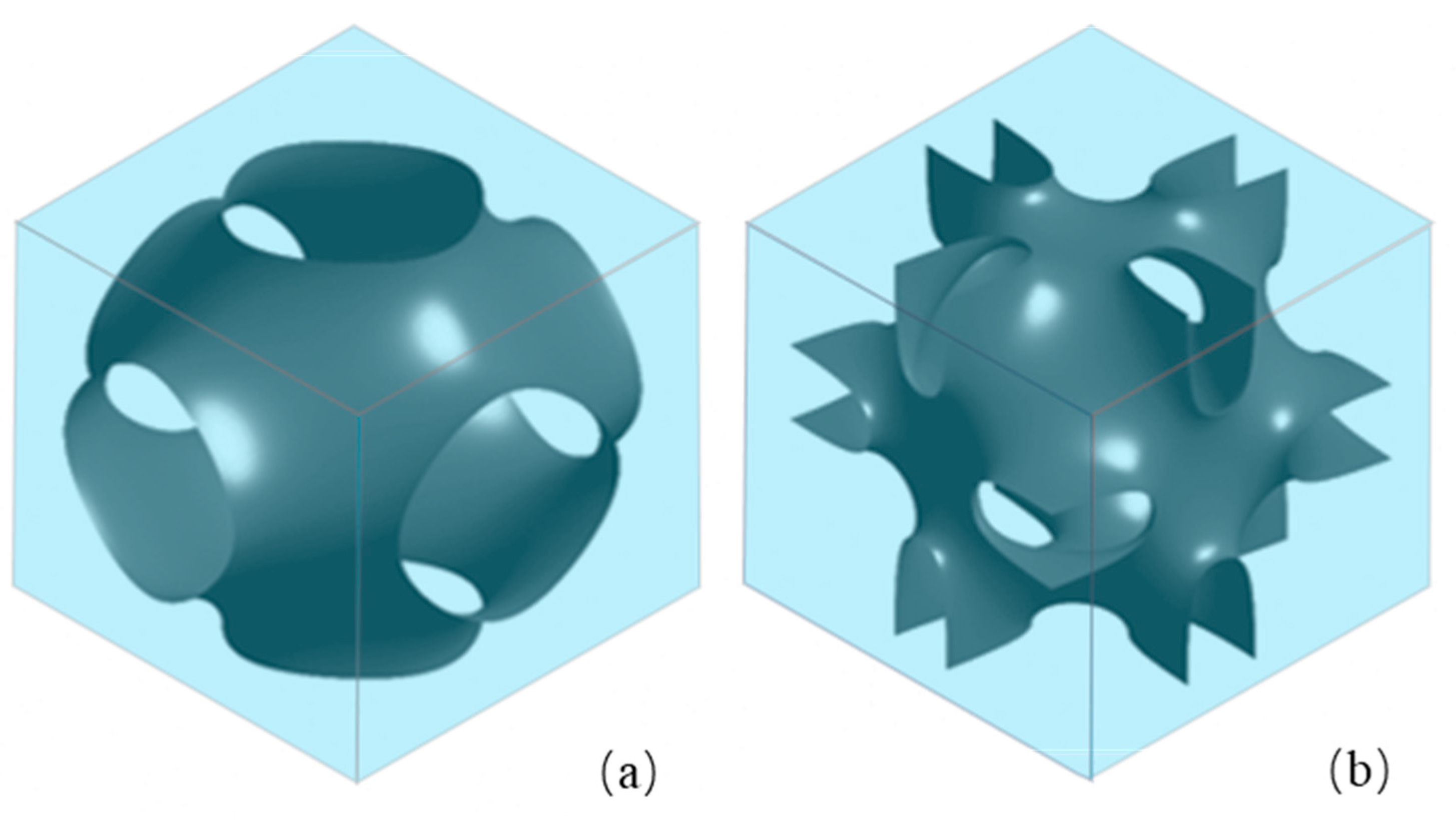
Figure 1 shows a three-dimensional model of the TPMS geometry created. TPMS can be mathematically approximated using implicit methods [
32]. The geometries were created by extracting the zero level-set surface from Equations (1) and (2), namely, the surface defined by f = 0. These surfaces can be trigonometrically approximated using the following level surface equations [
22]:
where x, y, and z are spatial coordinates, equations define Schwarz P and Neovius surfaces with cubic unit cells, ω = 2π/l, and l is the length of a unit cell. f is defined as the ratio of the inner sub-volume to the overall volume.
Finite element (FE) analysis was used to evaluate the piezoelectric response of the composite models. A custom MATLAB (R2023b) algorithm was developed to generate the TPMS geometries based on their implicit equations (Equations (1) and (2)) and to calculate the volume fraction of the piezoelectric ceramic phase. The algorithm adjusted the level-set threshold to achieve target volume fractions (10%, 15%, and 20%) and exported the surface data for subsequent meshing in HyperMesh (Version 2023). This approach leveraged MATLAB’s strengths in mathematical modeling and volumetric computation, while the finite element analysis was performed using specialized software (Abaqus 2023) nsure accuracy and reliability. Numerical simulations of cement-based piezoelectric composites were performed using commercial FE software: HyperMesh for geometry discretization and Abaqus for multiphysics analysis. Due to the geometric complexity of TPMSs, linear tetrahedral elements (C3D4E) were selected instead of hexahedral elements to accurately capture the smooth curvature of the structures. The FE model comprised a cubic representative volume element (RVE) with a side length of 50 mm. Seamless interfaces were assumed, with ceramic and polymer components sharing the same nodes in adjacent elements. The FE models employed are deterministic. Given the periodic and defined architecture of the TPMS, 1–3, and 0–3 unit cells, each simulation for a specific geometry and volume fraction yields a unique result. Therefore, error bars stemming from material or geometric randomness are not presented for these comparative simulations.
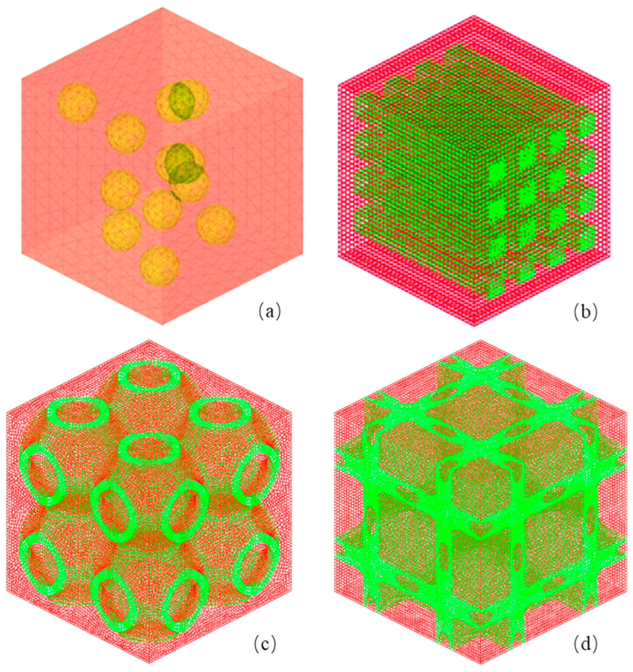
Figure 2 illustrates the configuration with a 15% volume fraction of piezoelectric ceramics. Lead zirconate titanate (PZT-7A) ceramics were selected to be integrated into the cement (depicted in red) to create the cement-based piezoelectric composite material.
The piezoelectric responses of the 3D composites were evaluated under cyclic loading conditions involving periodic pressing and releasing, as depicted in
Figure 3. These responses were effectively captured through finite element modeling of stress and piezoelectric coefficients within the composites. In our simulation, the piezoelectric ceramics were represented as isotropic elastic materials with their polarization direction orientated perpendicularly to the surface of the cement-based composites. To simulate the system, a simulation cell of characteristic size equivalent to the specimen thickness was constructed by periodically connecting Kelvin cells, as illustrated in
Figure 3. In cases of intricate models featuring periodic microstructures, suitable Representative Volume Elements (RVEs) were defined, periodic boundary conditions were imposed, and finite element numerical computations were performed. The collective behavior of these representative cells is used to characterize the overall structural response. At the boundary of a periodic unit cell, the displacement can be mathematically expressed as follows [
33]:
where the first term on the right represents the linear distribution of displacement, and the second term is the periodic part.
In the simulation context, material selection plays a pivotal role in defining the properties of piezoelectric composites. Initially, materials with piezoelectric properties were predominantly discovered in crystal structures like tourmaline, quartz, topaz, cane sugar, and Rochelle salt. However, their practical utility was limited by their low efficiency and brittleness [
3]. In this study, PZT ceramics were chosen for their robust piezoelectric traits, allowing them to effectively react to external stimuli such as pressure and vibrations [
17]. Additionally, Portland cement, primarily composed of calcium silicate and mineral powder, was chosen as the base for composite materials due to its high strength, exceptional durability, and advantageous plasticity [
34]. The relevant material parameters of the composite system are outlined in
Table 1.
The FE method is then used to predict the piezoelectric properties of the cement-based piezoelectric composites under different pressures, by taking an RVE. Elastic and piezoelectric effects are taken into account, and the model excludes nonlinearities as well as dissipative effects. The current constitutive model incorporates linear piezoelectric and elastic behavior for both the PZT and cement phases, which neglects nonlinear and dissipative effects such as hysteresis, creep, and material aging. This simplification is employed to elucidate the fundamental mechanisms of electromechanical coupling specific to the TPMS architectures being studied. Although these assumptions are suitable for evaluating short-term, idealized performance and enabling comparative analysis across different geometries, they consequently limit the model’s applicability for predicting long-term behavior under real-world conditions. For piezoelectric materials, the constitutive equations can be expressed as follows [
35]:
where the elastic strain
and electric field
are taken as the independent variables and are related to the stress
and the electric displacement
,
,
, and
are the elastic moduli (measured in a constant electric field), the piezoelectric coefficients (measured at a constant strain or electric field), and the dielectric constants (measured at a constant strain), respectively, with
,
,
, and
varying from 1 to 3 and being related to the coordinate axis. Average piezoelectric coefficients
,
, and
are usually used to evaluate piezoelectric effect, given as follows [
36]:
where the piezoelectric coefficient is
d and the mechanical stress is
T. The piezoelectric constant
is one of the most commonly used and important parameters to characterize the properties of piezoelectric materials. Generally, the higher the piezoelectric constant of ceramics, the better their piezoelectric performance. The first number in the subscript refers to the direction of the electric field, and the second number refers to the direction of stress or strain.
The effective piezoelectric coefficient
d33 of the composite RVEs was determined numerically through the finite element analysis. A uniaxial compressive stress (
T3) was applied along the
z-axis, which was aligned with the predefined polarization direction of the piezoelectric ceramic phase. The resultant average electric displacement component (
D3) in the
z-direction was computed by the FE solver by integrating the local electrical responses across the entire model. The volume-averaged effective
d33 coefficient was then calculated post-processing using the following fundamental relation:
This numerical approach inherently accounts for the directional dependence (anisotropy) of the piezoelectric response. The full piezoelectric tensor (including d33, d31, and d15) of the PZT-7A phase was incorporated into the constitutive model. The applied mechanical load and the measured electrical response are explicitly defined along the principal axes, ensuring that the calculated average piezoelectric coefficient specifically characterizes the coupling efficiency in the poling direction under uniaxial stress.
Moreover, d
33 is the average piezoelectric charge coefficient obtained directly from our finite element simulation under uniaxial stress. This value represents the effective electromechanical coupling of the entire composite RVE.
ɛ33 is the dielectric constant at constant stress. For the composite, this was estimated using a simple rule of mixtures, based on the volume fraction of the PZT-7A ceramic and the cement matrix, as provided in
Table 1. The piezoelectric voltage coefficient can be defined as follows [
37]:
The electric potential (
V) generated across the composite under mechanical load was directly obtained from the finite element simulation results. Specifically, the potential difference between the top and bottom surfaces of the Representative Volume Element (RVE) was extracted as the primary output variable. This computed value represents the open-circuit voltage generated by the piezoelectric composite due to the applied stress. For context in a homogeneous material under a uniform electric field, the output electrical potential (
V) generated across the thickness of the composite under an applied stress can be calculated using the following equation [
38]:
where
T denotes the magnitude of the applied uniaxial mechanical stress and
t represents the thickness of the composite sample measured along the poling direction.
3. Results
In this study, four piezoelectric ceramic architectures in cement-based composites were systematically compared: (i) randomly distributed spherical PZT particles (0–3 connectivity), (ii) one-dimensionally interconnected PZT rods (1–3 connectivity), (iii) bicontinuous Schwarz P (BP) structures, and (iv) bicontinuous Neovius (BN) structures. All RVEs were standardized at 50 × 50 × 50 mm3, with periodic boundary conditions applied in the x/y-directions to simulate infinite periodicity. Mechanical stress was applied unidirectionally along the z-axis (thickness direction), with indices 1/2/3 corresponding to the x/y/z-axes, respectively.
Simulations were performed under two loading scenarios: 0.7 kN (pedestrian equivalent) and 15 kN (vehicular equivalent).
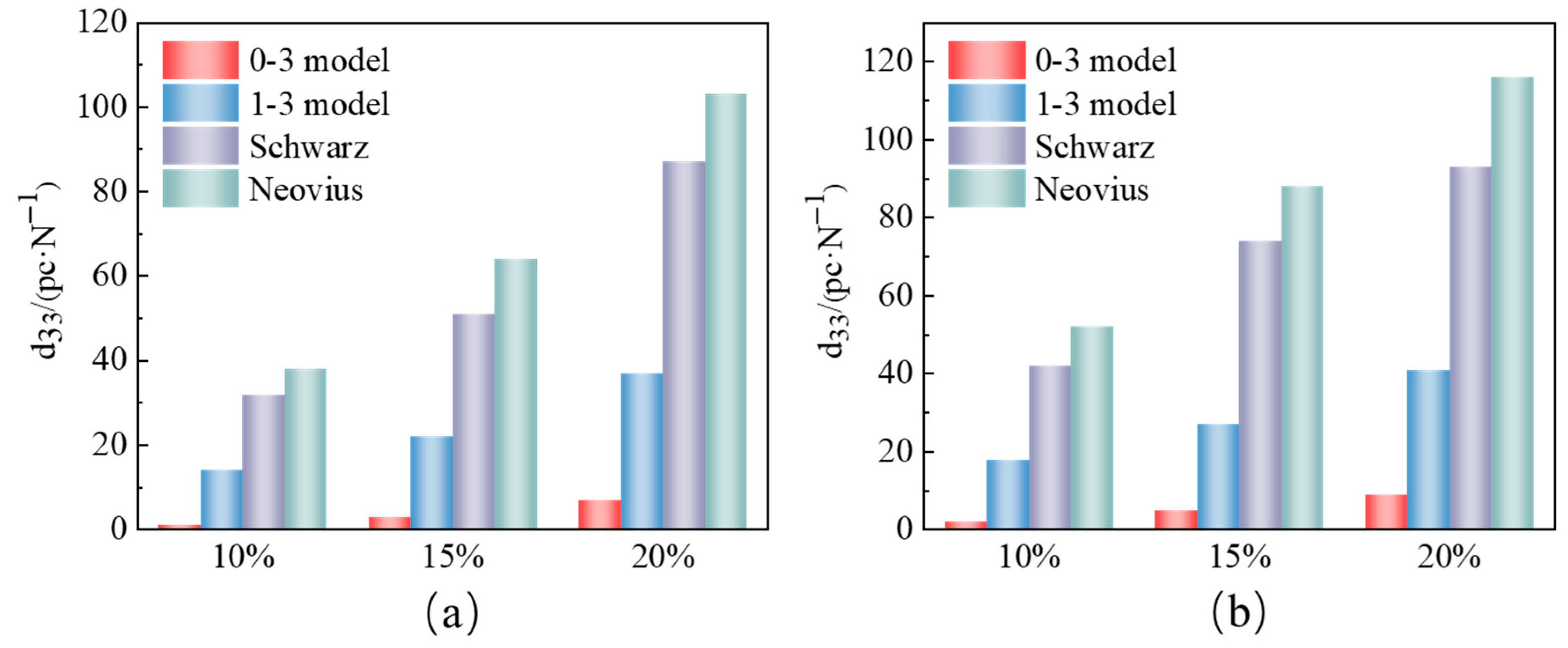
Figure 4a,b present the average piezoelectric coefficients (d
33) of the four structures at ceramic volume fractions (VFs) of 10%, 15%, and 20%. Notably, (d
33) increased monotonically with the VF for all architectures, highlighting the critical role of ceramic content in piezoelectric performance. The bar chart clearly demonstrates the significant influence of piezoelectric ceramic content on the performance of cement-based piezoelectric composites. The average piezoelectric coefficient of the four types of piezoelectric composite materials increases with the rise in PZT piezoelectric ceramic content. Among the cement-based piezoelectric composites under pedestrian loading (
Figure 4a), BN piezoelectric ceramic cement-based composites exhibit the highest average piezoelectric coefficient. With a volume fraction of 20% for PZT ceramics, the average piezoelectric coefficient of BN cement-based piezoelectric composite material reaches up to 103 pC/N. Additionally, the BP cement-based composite material demonstrates a respectable average piezoelectric coefficient of 87 pC/N, followed by 37 pC/N for the 1–3 types, while the lowest average piezoelectric coefficient for the 0–3 types of cement-based piezoelectric composite material is 7 pC/N. Similarly, under car loading (
Figure 4b), the average piezoelectric coefficient of cement-based piezoelectric composites with the four different structures can reach 116 pC/N and 93 pC/N for BN and BP piezoelectric ceramic structures, respectively, when the volume fraction of piezoelectric ceramics is 20%. These numerical results significantly surpass those of the 1–3 types (41 pC/N) and the 0–3 types (9 pC/N). This highlights the favorable piezoelectric properties exhibited by both BN and BP piezoelectric ceramic structures in cement-based composite materials. Evidently, the internal structure of piezoelectric ceramics plays a crucial role in enhancing the piezoelectric performance of cement-based piezoelectric composites.
At the micro level, the superior piezoelectric performance of BN and BP structures can be attributed to their unique charge transfer mechanisms and interactions with piezoelectric ceramics. In the BN and BP structures, the continuous and interconnected framework provides an efficient pathway for charge transfer. When mechanical stress is applied, piezoelectric ceramics generate charges. In the 0–3 type structure, due to the random distribution of piezoelectric ceramic particles, the charge transfer path is tortuous and discontinuous, resulting in significant charge loss during transfer. However, in BN and BP structures, charges can migrate smoothly along the continuous interface of the TPMS structure, which greatly improves the charge transfer efficiency and thus enhances the average piezoelectric coefficient. Moreover, the interaction between the BN and BP structures and piezoelectric ceramics is also crucial. The surface morphology and atomic arrangement of the TPMS structure are highly compatible with the piezoelectric ceramic phase. This compatibility enables effective stress transfer at the interface. When an external load is applied, the BN and BP structures can transfer stress to the piezoelectric ceramics more efficiently, allowing the piezoelectric ceramics to fully respond to stress changes and generate more charges, further improving the piezoelectric performance.
The piezoelectric voltage coefficient
G33, a crucial parameter in the realm of piezoelectric materials, not only serves as a key metric for gauging the strength of the piezoelectric effect but also stands as a significant indicator for unveiling the intrinsic characteristics of piezoelectric materials. It is noteworthy that the dielectric constant ε*
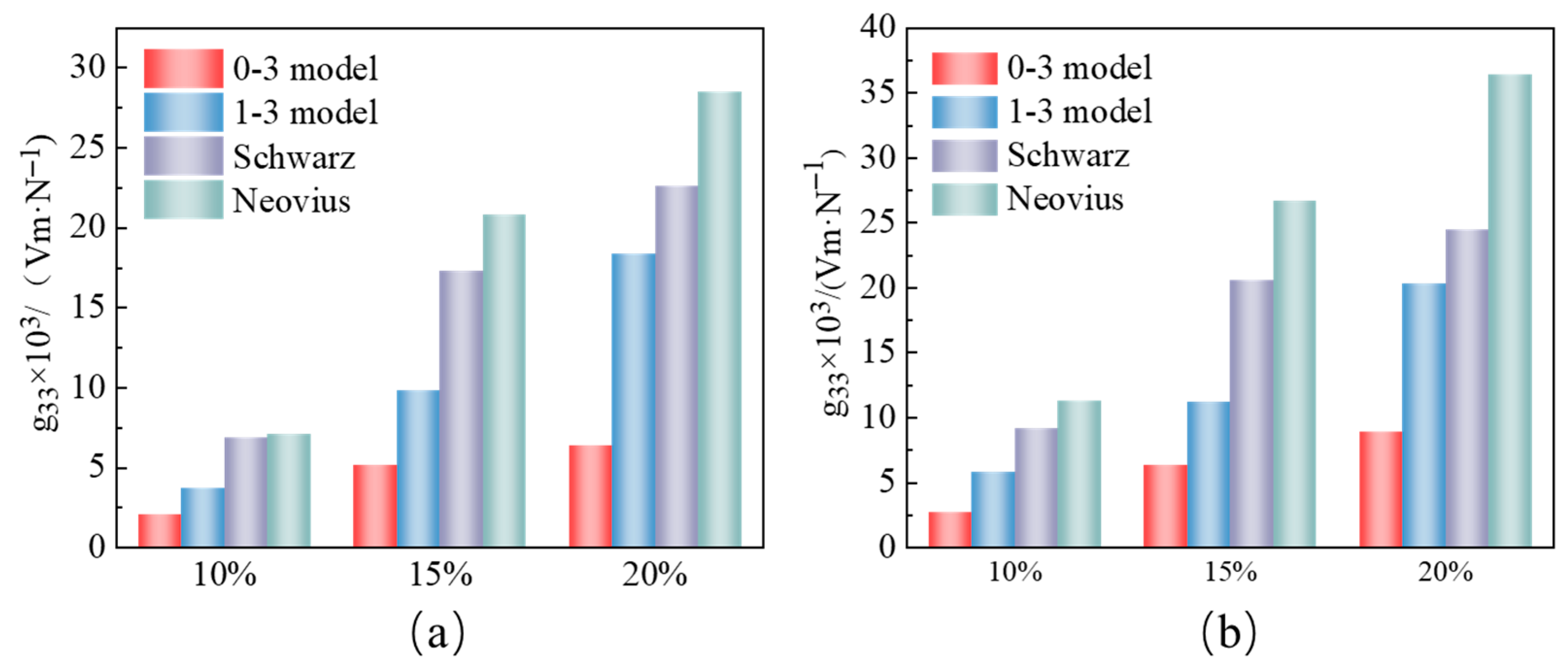
33 of cement-based piezoelectric composite materials is predominantly influenced by the dielectric properties of the cement matrix. In our investigation, we employed numerical simulations to compute the piezoelectric voltage coefficients of four distinct structures of cement-based piezoelectric composite materials under pedestrian and vehicular loads. As depicted in
Figure 5, it is evident that the piezoelectric voltage coefficients of the BP and BN structures surpass those of the 0–3 and 1–3 type cement-based piezoelectric materials under varying loads. Furthermore, across three different piezoelectric ceramic volume fractions, the piezoelectric voltage coefficients of the cement-based piezoelectric composite materials featuring BN and BP structures are notably higher than the other two types. When the piezoelectric ceramic volume fraction is set at 20% and under a 0.7 KN load, the piezoelectric voltage coefficient of the BN piezoelectric ceramic structure within the cement-based composite material demonstrates superior performance, reaching 10—approximately five times higher than that of the 0–3 type piezoelectric composite material. Moreover, at the same piezoelectric ceramic volume fraction, the piezoelectric voltage coefficient of the BN structure in the cement-based composite material reaches 36.4 × 10
−3 Vm/N under a 15 KN load, while the BP structure achieves 24.5 × 10
−3 Vm/N, in contrast with only 20.3 × 10
−3 Vm/N and 8.9 × 10
−3 Vm/N for the 1–3 and 0–3 type cement-based piezoelectric composite materials. Evidently, irrespective of the load magnitude, the cement-based composite materials featuring BN and BP piezoelectric ceramic structures exhibit commendable piezoelectric voltage coefficients. This excellent performance is also closely related to the charge transfer and structure–piezoelectric ceramic interaction. The continuous charge transfer path in BN and BP structures reduces the energy loss during the charge transfer process, which is beneficial for maintaining a high piezoelectric voltage coefficient. In terms of the interaction, the stable and interconnected structure of BN and BP can better fix the piezoelectric ceramic phase, reducing the internal stress concentration caused by the relative movement between different phases. This stable structure ensures that the piezoelectric ceramics can work under a more stable electrical environment, thereby improving the piezoelectric voltage coefficient.
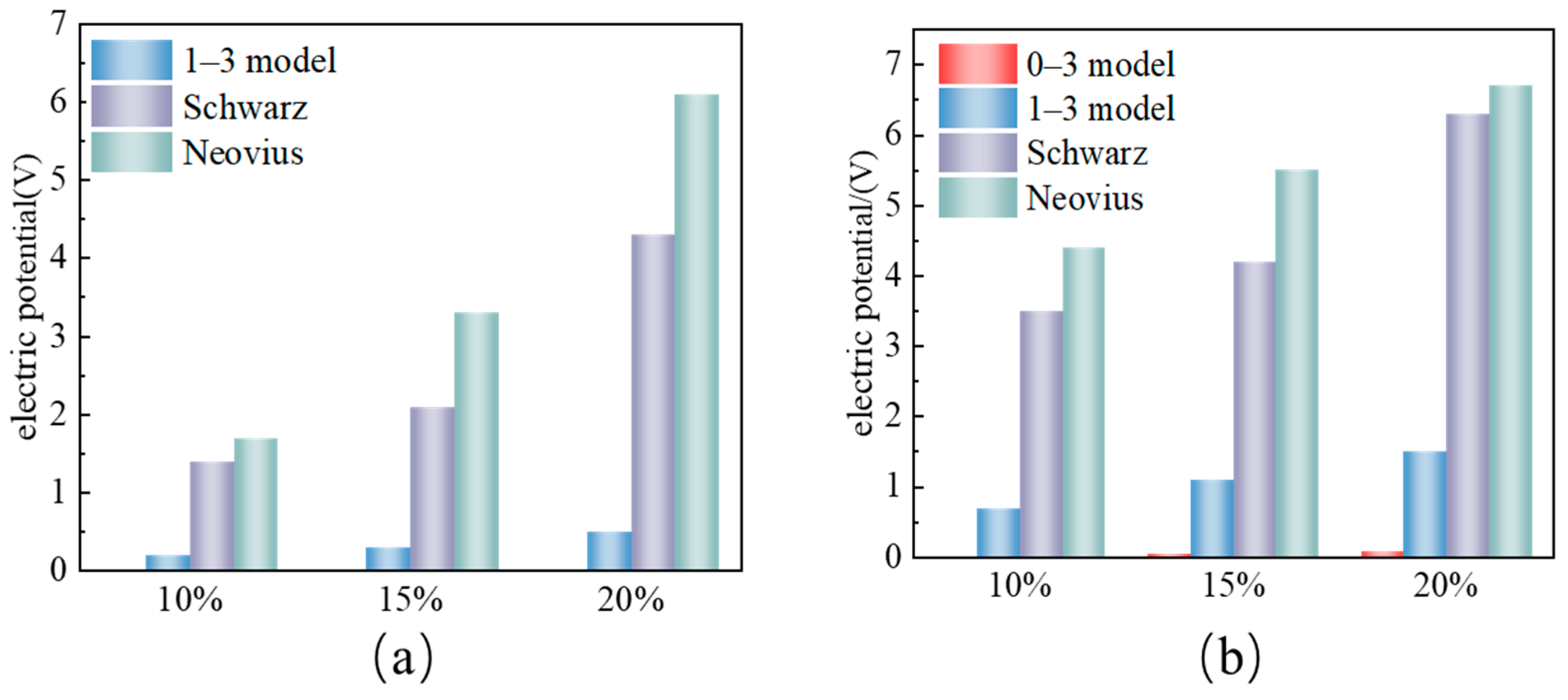
To further demonstrate the superior piezoelectric performance of BN- and BP-structured cement-based composites, we compared the electrical potential (V) across different internal architectures at identical PZT volume fractions (VF = 10%, 15%, 20%) using Equation (9). Quantitative analysis in
Figure 6 reveals a strong correlation between composite potentials and PZT content. Under a 0.7 kN load with 20% VF, BN, and BP composites generated 6.1 V and 4.3 V, respectively—values that significantly outperform the 0–3 (1.5 V) and 1–3 (0.08 V) structures. Increasing the load to 15 kN further enhanced potential outputs, with BN composites achieving a peak of 6.7 V at 20% VF—the highest among all configurations. The high potential values of BN and BP structures are mainly due to their efficient charge transfer and strong interaction with piezoelectric ceramics. The continuous charge transfer channels in these two structures can quickly collect and accumulate charges, increasing the potential difference. At the same time, the strong interaction between the structure and the piezoelectric ceramics promotes the complete polarization of the piezoelectric ceramics, generating more charges under the same load, which is also an important factor in the high potential performance. These findings highlight how TPMS geometries overcome the charge transfer limitations of traditional low-dimensional structures, offering a promising strategy for optimizing piezoelectric energy conversion in smart infrastructure.
To provide a direct and quantitative comparison of the piezoelectric performance among the four composite architectures, the key results for the 20% ceramic volume fraction under the 15 kN load are summarized in
Table 2. The table clearly highlights the superior performance of the TPMS-based composites, particularly the Neovius structure. It showcases the remarkable percentage improvement in the average piezoelectric coefficient (d
33), piezoelectric voltage coefficient (
G33), and generated potential over the conventional 0–3 and 1–3 composites. This quantitative comparison underscores the significant advantage afforded by the continuous, bio-inspired TPMS architectures in enhancing the electromechanical energy conversion efficiency.
Figure 7 provides a comprehensive visualization of the electrical potential distribution across different PZT ceramic architectures through color-coded mappings, where red indicates high-potential zones and blue denotes low-potential regions. Under gravitational loading, potential energy is observed to concentrate from the edges toward the center, with the central zone exhibiting the highest accumulation of potential. Of particular interest is the depiction in
Figure 7a, which showcases particulate piezoelectric ceramics. Here, the potential distribution is observed to be scattered and bereft of a definitive pattern, highlighting the complex and less predictable nature of potential variation within such structures. Turning to
Figure 7b, the 1–3 configuration of piezoelectric ceramics demonstrates a more uniform potential distribution accompanied by substantial potential output. However, the structural discontinuities inherent to this design hinder optimal potential conduction.
Figure 7c,d depict the upper potential layouts of the Schwarz and Neovius piezoelectric ceramic structures, respectively. Strikingly, these two configurations bear a remarkable similarity in their potential layouts. Both are characterized by an evenly dispersed potential, a trait that can be ascribed to the sleek, uninterrupted surfaces they possess. These surfaces facilitate efficient potential conduction, a feature that is advantageous for enhancing the piezoelectric performance of cement-based piezoelectric composites. In summary, the superior performance of BN and BP structures arises from their unique ability to enable efficient charge generation, continuous transfer, and uniform accumulation—mechanisms fundamentally constrained in traditional 0–3 and 1–3 composites by phase discontinuity and structural fragmentation. These findings underscore the critical role of micro-architectural design in optimizing piezoelectric behavior for next-generation smart materials.
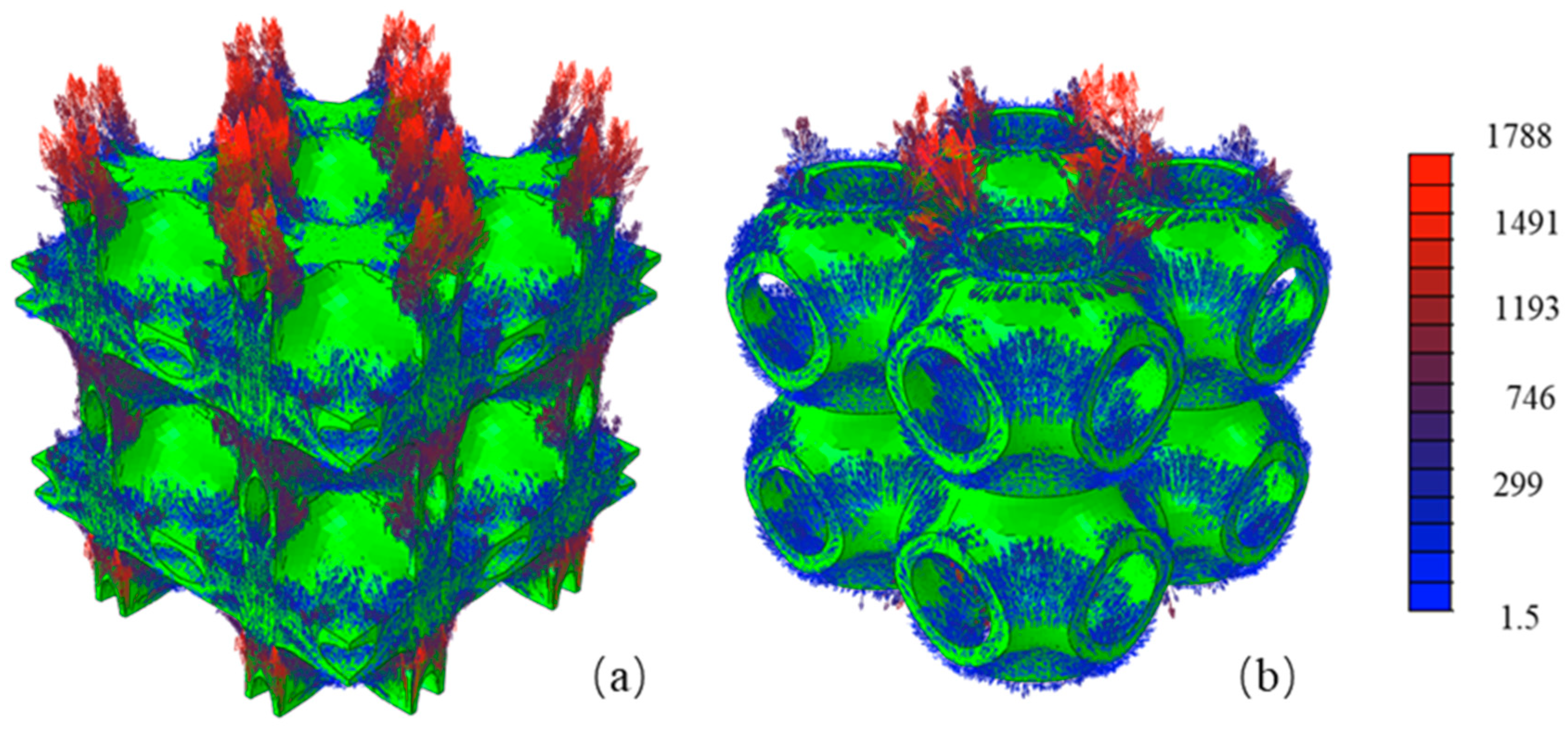
To gain deeper insights into the mechanism behind the superior performance of the TPMS architectures, we analyzed the current density distribution within the Schwarz P and Neovius structures under mechanical load.
Figure 8 presents the simulated current density magnitude (in A/m
2) for both structures at a 20% ceramic volume fraction. A striking observation is the formation of a continuous, three-dimensional network of high-current-density pathways (depicted in red and yellow) throughout both TPMS structures. This network mirrors the intricate and bicontinuous topology of the TPMS scaffolds themselves. The high-intensity currents are not confined to isolated channels but are distributed across the entire interconnected piezoelectric ceramic phase. This visualization provides direct quantitative evidence for the proposed “continuous charge transfer pathways”. When mechanical stress induces charge generation within the piezoelectric ceramic, these continuous pathways enable efficient and omnidirectional charge collection and transport, minimizing energy loss due to interfacial jumping or trapping that plagues discontinuous composites (like 0–3 and 1–3 types). The uniformity and high value of the current density within these networks are consistent with the significantly higher piezoelectric coefficients and voltage outputs measured for the TPMS composites, as shown in
Figure 4,
Figure 5 and
Figure 6. The Neovius structure (
Figure 8b) appears to sustain an even more extensive and robust current network than the Schwarz P structure (
Figure 8a), which correlates well with its marginally better performance metrics.
To better validate and contextualize our results, we compared the piezoelectric performance of our TPMS-structured composites with those of conventional cement-based composites reported in the literature. For instance, traditional 0–3 cement-based composites with PZT volume fractions as high as 50–60% typically exhibit d
33 values in the range of 25–35 pC/N [
8], which is significantly lower than the values achieved by our TPMS structures at only 20% ceramic volume fraction. This remarkable improvement underscores the limitations of random ceramic distributions and highlights the critical role of continuous architectural design in enhancing piezoelectric efficiency. Similarly, compared to 1–3 connectivity composites, which are considered superior to 0–3 types, our TPMS composites demonstrate a substantial advantage. Previous studies on 1–3 cement-based composites with a similar PZT volume fraction (~20%) reported d
33 values of approximately 40–50 pC/N [
14], which aligns well with our result of 41 pC/N for the 1–3 model. This agreement serves to validate the accuracy of our computational model. More importantly, our TPMS-based composites (93 pC/N for Schwarz P and 116 pC/N for Neovius) outperform these conventional 1–3 composites by a factor of 2.3 to 2.9, clearly demonstrating the benefit of the bicontinuous TPMS morphology in facilitating efficient stress transfer and continuous charge propagation. It is noteworthy that our cement-based TPMS composites, despite the inherent disadvantages of a stiffer and electrically less responsive cement matrix, achieve a performance that is not only comparable but even superior to many polymer-based systems. This further confirms the effectiveness of the TPMS architecture in maximizing the piezoelectric response, even in a challenging matrix material like cement.
In summary, the comparative analysis demonstrates that the piezoelectric properties of our TPMS-enhanced cement composites are not only analogous to, but significantly exceed, those of existing composite materials with similar or even higher ceramic volume fractions. The results are validated through their consistency with the performance of traditional 1–3 composites and their superior performance relative to both conventional cement-based and advanced polymer-based composites. The Neovius and Schwarz P structures effectively overcome the limitations of phase discontinuity, setting a new benchmark for high-performance piezoelectric composites in smart infrastructure applications.
While the piezoelectric performance metrics (
d33,
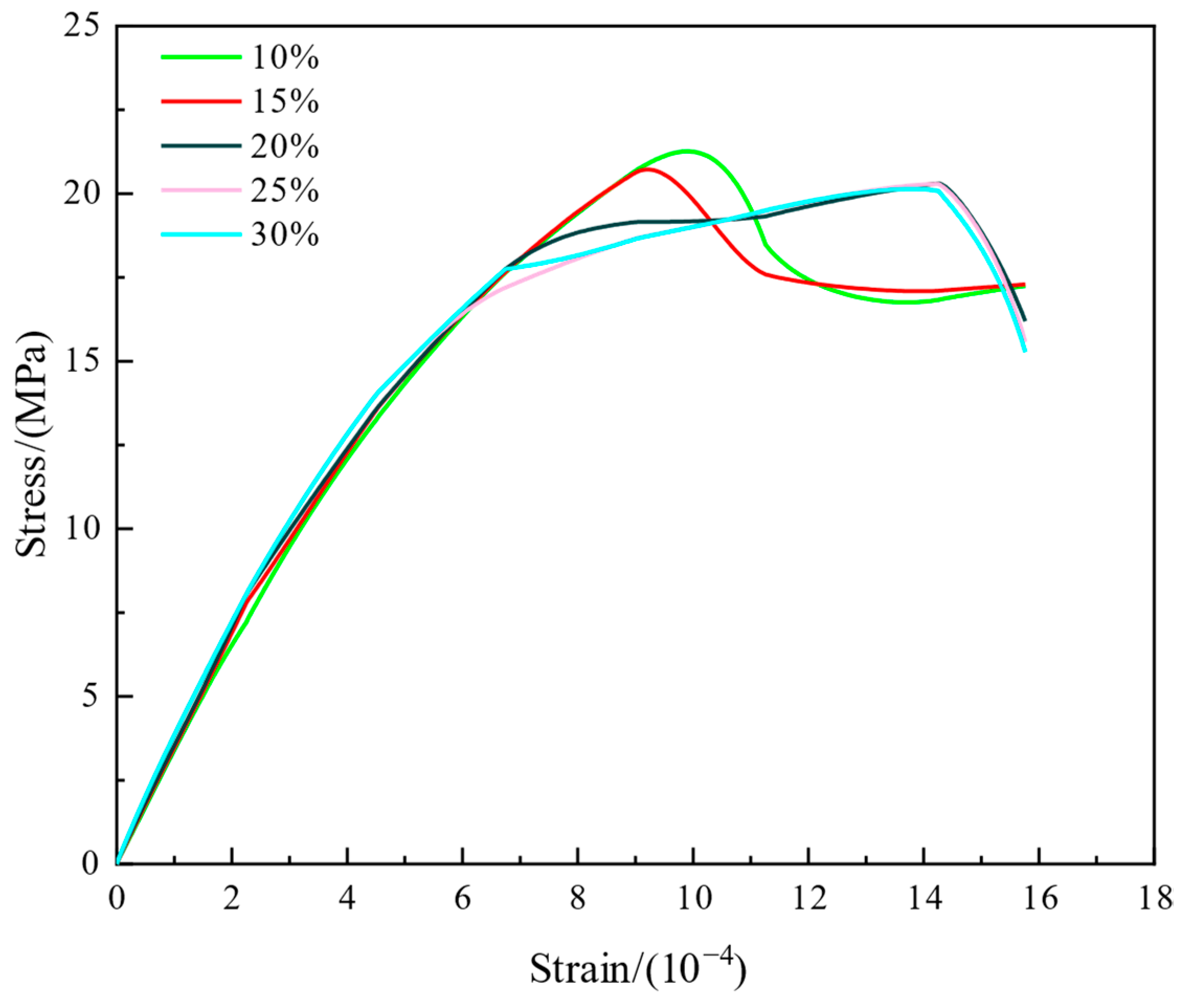
G33, and potential) exhibit a monotonic increase with the volume fraction of PZT, the mechanical integrity of the composite must be considered for structural applications. The compressive strength of the composites was evaluated across the same range of volume fractions (
Figure 9). A key finding was that the enhancement in compressive strength became marginal once the ceramic content exceeded 20%, with the curves for different architectures nearly converging. This indicates a saturation point in mechanical performance gains. Consequently, a volume fraction of 20% was identified as a practical optimum, offering a significant enhancement in piezoelectric properties without compromising the mechanical integrity of the cementitious matrix.
4. Discussion
The results demonstrate that cement-based composites with triply periodic minimal surface (TPMS) architectures—particularly the Neovius structure—achieve exceptional piezoelectric performance, outperforming conventional 0–3 and 1–3 composites by up to 12-fold in piezoelectric coefficients. This enhancement is attributed to the bicontinuous topology of TPMS, which overcomes phase discontinuity limitations in traditional composites by enabling efficient charge transfer pathways and uniform stress distribution across the piezoelectric ceramic phase. These findings validate the hypothesis that geometric optimization of ceramic architectures is critical for electromechanical coupling. This study positions TPMS-structured composites as transformative materials for self-sensing infrastructure (e.g., roads, bridges) where high energy-conversion efficiency is required. Future work should address scalable fabrication and environmental durability to enable these laboratory-scale innovations to transition toward real-world applications.
Despite the promising piezoelectric performance demonstrated in this numerical study, the environmental durability of these TPMS-enhanced cement-based composites under real-world conditions remains a subject for future investigation. Factors such as prolonged humidity exposure, which may compromise the matrix integrity and electrical insulation; temperature fluctuations, which can induce thermal stresses due to mismatched expansion coefficients; and mechanical wear/fatigue, particularly in applications like pavements or bridges, are expected to represent critical challenges. To address these issues, subsequent research should focus on strategies such as (1) incorporating hydrophobic agents or protective coatings to enhance water resistance; (2) optimizing the composite’s thermomechanical compatibility to mitigate thermal stress; and (3) evaluating the long-term mechanical abrasion and fatigue resistance, potentially through the use of high-performance matrices or surface treatments. Experimental validation under accelerated aging conditions will be essential to assess the long-term stability and viability of these smart composites for sustainable infrastructure applications.
The assumption of perfectly bonded, seamless interfaces between the PZT ceramic and the cement matrix represents an idealization that establishes an upper performance bound. In practice, the performance of cement-based composites is highly sensitive to interfacial conditions, including debonding, microcracks, and porosity, which can act as barriers to efficient stress transfer and charge propagation, thereby likely diminishing the piezoelectric output. A sensitivity analysis of interface properties was beyond the scope of this foundational study but is critical for assessing real-world viability. Therefore, future work will explicitly focus on incorporating interfacial imperfections using cohesive zone models and parametric studies to quantify their impact on the electromechanical coupling efficiency.
It is imperative to note that the present study evaluates performance under quasi-static loading conditions. While the selected load levels (0.7 kN and 15 kN) serve as useful benchmarks for comparing the fundamental electromechanical response of different architectures, they do not replicate the complex dynamic, cyclic, or impact loading that civil infrastructure materials endure in service. Consequently, the critical issues of fatigue life, long-term durability, and performance degradation under repeated loading remain unexplored. The absence of these analyses represents a key limitation of the current work. Therefore, future research must prioritize dynamic and cyclic mechanical testing to characterize the composite’s response to realistic loading spectra. This will involve investigating hysteresis losses, polarization fatigue, and the evolution of piezoelectric coefficients over thousands of load cycles. Such studies are indispensable in the transition of these material concepts from laboratory proof-of-concepts to viable solutions for long-term structural integration.
It is important to note that the findings presented in this study are derived solely from numerical simulations. While the finite element model provides valuable insights into the structure–property relationships of TPMS-based composites, their practical implementation faces significant fabrication challenges. These include ensuring the integrity of the continuous ceramic phase and achieving perfect interfacial bonding within cementitious matrices. These challenges constitute the main focus of our ongoing research. Future work will prioritize employing advanced manufacturing techniques, such as 3D printing of ceramic scaffolds, to fabricate these composite architectures. The fabricated samples will then be experimentally characterized to validate the simulated piezoelectric properties under mechanical loading. Furthermore, the long-term durability and environmental stability of these smart composites will be investigated to assess their viability for real-world applications.
Despite the promising piezoelectric performance demonstrated in this numerical study, the practical fabrication of these TPMS architectures at a construction scale presents significant challenges. The assumed geometric precision and continuity of the ceramic phase within a cementitious matrix are difficult to achieve with conventional casting techniques. Future work will focus on employing advanced manufacturing strategies, such as 3D printing of ceramic scaffolds or indirect replication methods, to achieve these complex architectures. The scalability of these processes and the performance of composites with feature sizes applicable to construction-grade materials will be the subject of subsequent experimental investigations.
