Article

Performance Analysis of Multi-OEM TV White Space Radios in Outdoor Environments

Council for Scientific and Industrial Research (CSIR), Next-Gen Enterprises and Institutions (NGEI), Pretoria 0001, South Africa
*
Author to whom correspondence should be addressed.
Appl. Sci. 2025, 15(18), 9977; https://doi.org/10.3390/app15189977
Submission received: 21 July 2025 / Revised: 28 August 2025 / Accepted: 29 August 2025 / Published: 12 September 2025
(This article belongs to the Special Issue Applications of Wireless and Mobile Communications)

Abstract

The television white space (TVWS) spectrum presents a promising opportunity to extend wireless broadband access, particularly in rural, underserved, and hard-to-reach communities. To leverage this potential, low-power radio communication equipment must efficiently utilise the TVWS spectrum on a secondary basis while ensuring strict compliance with regulatory requirements to prevent harmful interference to primary services. This paper presents a comparative performance analysis of TVWS radio equipment from three original equipment manufacturers (OEMs). The equipment under test was identified to reflect each OEM, as follows: OEM 1 and OEM 2 from South Korea and OEM 3 from the USA. We evaluated their performance in two real-world field scenarios, namely outdoor short-distance and outdoor long-distance. The evaluation was based on the following key metrics: (i) spectrum utilisation efficiency (SUE), (ii) received signal strength (RSS), (iii) downlink throughput, and (iv) connectivity to the Geo-Location Spectrum Database (GLSD) in compliance with the South African TVWS regulatory framework. The overall preliminary experimental results indicate that in both scenarios, white space devices (WSDs) based on the Institute of Electrical and Electronics Engineers (IEEE) 802.11af Standard demonstrated better performance than those based on the 3rd Generation Partnership Project Long-Term Evolution-Advanced (3GPP LTE-A) Standard in terms of the SUE, downlink throughput, and RSS metrics. All WSDs under test demonstrated sufficient compliance with the regulatory requirement metric.

1. Introduction

Several national regulatory authorities (NRAs) across the world have introduced a lightly managed dynamic spectrum access (DSA) regime for low-power radio equipment. Such equipment harnesses the unoccupied portions of the broadcast television spectrum in the time, frequency, and space domains. These unoccupied portions of the spectrum are known as television white space (TVWS). In South Africa, the TVWS spectrum is located within the ultra-high frequency (UHF) band [1,2,3,4]. The UHF band is primarily used for TV broadcasting and dates back to the era of analogue TV broadcasting, continuing after the digital switch-over (DSO). The transition from analogue to digital TV broadcasting does not increase the availability of the TVWS spectrum; instead, it often reduces it. A portion of the freed spectrum, known as the digital dividends (DDs), is typically reallocated for other services such as those based on the International Mobile Telecommunications (IMT) Standard [4]. For example, in South Africa, up to 48 television channels could potentially offer white space opportunities before the DSO. After the DSO, there are only around 28 channels in each area of interest due to the reallocation of frequencies for mobile broadband and other services.
TVWS presents a novel opportunity to address the growing global demand for wireless broadband, particularly in rural and underserved areas [5]. TVWS can facilitate the provision of low-cost, high-speed internet access, thereby narrowing the digital divide. It offers an alternative to typical broadband infrastructure, which is frequently expensive and logistically challenging to extend to remote areas [6,7,8,9,10,11,12,13]. In South Africa, women and youth-owned information and communication technology (ICT) small, medium, and micro enterprises (SMMEs) are leveraging the TVWS spectrum to deploy broadband networks in rural and township areas. These initiatives are bridging the digital divide while creating hundreds of jobs for local women and youth. This demonstrates TVWS’s potential for both connectivity and economic empowerment [14].

1.1. Characteristics of Radio Communication Equipment Operating in the TVWS Spectrum

The radio equipment that operates in the TVWS spectrum is also known as a WSD. Multiple devices are denoted as WSDs. WSDs predominantly follow software-defined radio (SDR) architecture for dynamic frequency tuning, which enables operation over a broad spectrum range. A WSD is low-power, fixed or nomadic device that can be categorised as either a Master or a Client. A Master (base station) connects to the internet backhaul (gateway) and communicates with the GLSD. A Client, also known as customer premises equipment (CPE), associates with a Master and provides last-mile connectivity to end users.
The design of WSDs differs from one original equipment manufacturer (OEM) to another. Most OEMs follow a traditional design approach that produces two separate devices: a Master and Client. Other OEMs follow a contemporary design approach, featuring a unified WSD with dual functionalities for both Master and Client. The latter design approach allows the operator to configure the device functionalities based on the device category programmatically [15].
WSDs are usually required to adhere to defined regulations, standards, and protocols. Hereafter is an overview of sample TVWS regulatory frameworks and types of approval processes, as well as common standards and protocols.

1.2. Underlying TVWS Regulatory Framework

Harnessing the TVWS spectrum in the UHF television band is governed differently by regulatory bodies globally. Each regulator has developed a framework that allows DSA while ensuring protection for incumbent users such as broadcast TV and wireless microphones. Below is a brief overview of the regulatory requirements in selected countries.
ICASA of South Africa: The Independent Communications Authority of South Africa (ICASA) has established a regulatory framework to govern the use of TVWS. The framework has a strong emphasis on DSA and opportunistic spectrum management, while protecting the incumbent TV broadcasting services and radio astronomy services (RAS). This is facilitated through two-tier GLSDs: a Reference-GLSD (R-GLSD), operated by ICASA, and a Secondary-GLSD (S-GLSD), operated by a designated entity [10,16,17]. Under this framework, WSDs are required to access a certified S-GLSD to determine which frequencies are available for use in their location. Additionally, WSDs must be type-approved by ICASA and must operate within defined power limits to minimise interference.
FCC of the United States: The Federal Communications Commission (FCC) was the first regulatory body to implement a framework for the use of TVWS. The FCC regulations permit both fixed and portable WSDs to operate under strict conditions [18,19,20,21]. WSDs are required to use FCC-approved GLSDs to determine available frequencies, while accurately identifying their location using the Global Positioning System (GPS) or other reliable positioning methods. Power levels are tightly controlled, with fixed devices limited to a maximum of 4 watts, as measured by effective isotropic radiated power (EIRP). Additionally, fixed WSDs must register with the GLSD. WSDs are also required to perform periodic re-checks to ensure ongoing compliance and avoidance of interference.
Ofcom of the United Kingdom: The UK’s communications regulator, Ofcom, supports the licence-exempt use of TVWS through a DSA model [2,22]. This approach requires all WSDs to interact with designated Ofcom-certified GLSDs to determine available frequencies. WSDs must adhere to strict technical parameters, including maximum power levels and emission mask requirements, to minimise interference. Additionally, devices are required to report their location and operational capabilities to the GLSD to ensure appropriate frequency assignment. Ofcom focuses on mitigating interference to protect incumbent primary services such as digital television and wireless microphones.
IMDA of Singapore: The Infocomm Media Development Authority (IMDA) of Singapore has developed a regulatory framework grounded on DSA principles [23,24]. Under this framework, WSDs must connect to a GLSD to identify available channels before transmitting. While the use of TVWS is licence-exempt, it is subject to stringent technical requirements designed to ensure efficient and interference-free use of the spectrum. The framework places particular emphasis on protecting existing digital television services while simultaneously promoting reliable and robust connectivity for new wireless applications.
CEPT of Europe: The European Conference of Postal and Telecommunications Administrations (CEPT) has established a regulatory framework, anchored by the Radio Equipment Directive (RED), which requires WSDs to dynamically access spectrum via EU-authorised GLSDs and adhere to the European Telecommunications Standards Institute (ETSI) EN 301 598 [25,26]. Operation is also licence-exempt but subject to stringent requirements to ensure coexistence with existing services.

1.3. Equipment Type Approval Certification

Type approval, also known as equipment type certification, is a mandatory regulatory requirement for deploying WSDs to ensure that these devices meet national and international technical standards for safe and interference-free operation. Most national regulators have a similar overarching goal of ensuring coexistence with licensed services and protecting users. However, specific certification processes and requirements vary by country. Below is a brief overview of the electromagnetic compatibility (EMC), electrical safety, and spectrum use requirements in selected countries.
South Africa: ICASA mandates all WSDs to undergo type approval before being marketed or operated [16,27]. Devices must be tested for compliance with EMC standards, typically referencing international norms such as CISPR 32 [28] or EN 301 489 [29]. Regarding electrical safety, ICASA aligns with IEC 60950-1 [30] and IEC 62368-1 [31], requiring manufacturers to demonstrate that their devices meet safety requirements to prevent electrical hazards. For spectrum use, ICASA requires that devices operate within the defined UHF band (470–694 MHz). They must comply with DSA requirements via certified GLSD and adhere to emission masks and power limits to avoid interference with incumbent services.
USA: The FCC requires all WSDs to be certified under Part 15 of its rules for unlicensed devices. Devices must comply with EMC requirements outlined in FCC Part 15B to prevent harmful interference with licensed services. While the FCC does not directly test devices for electrical hazards, it defers to the Underwriters Laboratories (UL) or other Nationally Recognised Testing Laboratory (NRTL) certifications as part of broader compliance processes, especially for consumer-grade equipment. For spectrum use, WSDs must operate within the designated TV bands (54–698 MHz) and use FCC-approved GLSDs [21,32,33]. The devices are also subject to stringent out-of-band emission (OOBE) requirements (e.g., 55 dBc adjacent channel attenuation).
UK: Ofcom does not perform direct type approval but requires compliance with ETSI standards, particularly ETSI EN 301 598 for TVWS [34,35]. EMC compliance is assessed against ETSI EN 301 489-1 and EN 301 489-17 [36,37], ensuring that WSDs do not emit unintended radio frequency (RF) energy that could disrupt other services. For electrical safety, compliance with the UK Electrical Equipment (Safety) Regulations and conformity to EN 62368-1 [38] is expected. Products must carry the CE or UKCA mark, indicating conformity to safety and EMC directives. In terms of the spectrum use, devices must dynamically access spectrum using an Ofcom-authorised geo-location database and remain within defined power and interference mitigation limits.
Singapore: The IMDA mandates that all WSDs undergo type approval prior to importation, sale, or use in Singapore. IMDA adopts and enforces EMC standards such as CISPR 32, along with ETSI EN 301 489 for radio equipment [39,40,41]. On electrical safety, devices must comply with IEC 60950-1 or IEC 62368-1 and be tested by recognised conformity assessment bodies (CABs). Devices must also bear the IMDA compliance label upon approval. For spectrum use, IMDA requires that devices comply with technical specifications in the technical specification for short-range devices (TS SRD). They must also interface with an approved central database for dynamic frequency allocation within the TVWS band.
Europe: TVWS regulations are largely harmonised through the ETSI and European Commission directives. The primary technical standard governing WSD operation is ETSI EN 301 598, which defines requirements for DSA, including geo-location functionality and coordination with certified databases [25]. To ensure EMC, devices must comply with ETSI EN 301 489-1 and EN 301 489-17, minimising harmful interference with licensed services [29]. Electrical safety is governed by the Low Voltage Directive (LVD) and typically demonstrated through compliance with EN 62368-1, which covers audio/video and information technology (IT) safety equipment [26]. WSDs must bear the European conformity marking to indicate conformity with safety, EMC, and radio equipment requirements. Spectrum use is regulated under the RED 2014/53/EU [42], requiring WSDs to operate within strict power and interference limits while connected to an EU-authorised geo-location database [43]. Cross-border co-ordination within the EU aims to ensure the interoperability of WSDs and the consistent application of rules across member states.

1.4. Underlying Technical Standards and Protocols

Multiple technical standards and protocols have been designed or adapted to support radio communication equipment for use of the TVWS spectrum. Key radio standards include (i) the Institute of Electrical and Electronics Engineers (IEEE) 802.11af, (ii) IEEE 802.22, (iii) European Computer Manufacturers Association-392 (ECMA-392), (iv) the 3rd Generation Partnership Project Long-Term Evolution-Advanced (3GPP LTE-A), and (v) the Internet Engineering Task Force (IETF) Protocol to Access White Space (PAWS) Database Request for Comments (RFC) 7545. Most of these standards and protocols have been implemented in the devices under test, thus influencing the performance. An overview of these standards and protocols is provided next:
IEEE 802.11af/White-Fi: IEEE 802.11af [44,45,46], also known as White-Fi, is designed to enable conventional Wi-Fi devices to utilise the TVWS spectrum. At the physical layer, it supports channel bandwidths of 6, 7 or 8 MHz, depending on the regional TV channel specifications. It employs orthogonal frequency division multiplexing (OFDM) modulation, supporting binary phase shift keying (BPSK), quadrature phase shift keying (QPSK), 16-quadrature amplitude modulation (QAM), and 64-QAM schemes, with a subcarrier spacing of 312.5 kHz. The standard also allows for multiple-input multiple-output (MIMO) configurations with up to four spatial streams. It utilises time division duplexing (TDD). On the MAC layer, IEEE 802.11af is based on carrier sense multiple access with collision avoidance (CSMA/CA), incorporating mechanisms to access geo-location databases for regulatory compliance. It also supports dynamic frequency selection and transmits power control to adapt to changing spectrum conditions.
IEEE 802.22 WRAN: IEEE 802.22 [47,48,49], also known as Wireless Regional Area Network (WRAN), is designed to deliver long-range backhaul broadband access specifically targeting rural and underserved regions by utilising the TVWS spectrum. At the physical layer, it typically operates with a 6 MHz channel bandwidth, though 7 and 8 MHz configurations are also supported depending on the region. The standard utilises orthogonal frequency division multiple access (OFDMA) modulation and supports a range of schemes, including BPSK, QPSK, 16-QAM, and 64-QAM, with a subcarrier spacing of 10.94 kHz. It allows for optional antenna diversity and MIMO capabilities and supports both TDD as the primary mode and frequency division duplexing (FDD) as an option. The MAC layer employs a centralised architecture involving a base station and CPE. It supports quality of service (QoS), scheduling, and dynamic channel access and includes mechanisms to protect incumbent users and ensure coexistence with other spectrum users.
ECMA-392: The European Computer Manufacturers Association – 392 is a standard developed for short-range, personal or portable cognitive radio systems that operate within the TVWS spectrum, particularly suited for short-range, indoor environments [50,51]. At the physical layer, it typically utilises channel bandwidths of 6, 7, or 8 MHz and employs OFDM modulation, supporting schemes ranging from BPSK to 64-QAM. The subcarrier spacing is 43.07 kHz, achieved through a 256-point fast Fourier transform (FFT) over a 10.5 MHz bandwidth. Unlike other standards, ECMA-392 does not support MIMO, focusing instead on low-complexity devices. It uses TDD for bidirectional communication. The MAC layer is distributed and combines elements of both time division multiple access (TDMA) and carrier sense multiple access (CSMA). It incorporates spectrum sensing and beaconing to enable coexistence with other users and supports decentralised coordination among devices.
3GPP LTE-A: The 3rd Generation Partnership Project Long-Term Evolution-Advanced (3GPP LTE-A) Standard supports operations in the UHF spectrum range, also known as the lower-band spectrum. This has enabled the successful deployment of LTE-based WSDs utilising the TVWS spectrum. It is facilitated through IETF RFC 7545 PAWS and the GLSD by leveraging features such as carrier aggregation and flexible bandwidth configurations [52,53]. Notably, LTE Band 71, which operates in the 600 MHz spectrum range (617–652 MHz), falls within the broader TVWS frequency range. This alignment makes it technically feasible for LTE/4G-capable devices to operate within the TVWS spectrum, provided they comply with local regulatory and database coordination requirements. At the physical layer, LTE supports channel bandwidths of 5, 10, and 20 MHz, with adaptations available for 6 and 8 MHz to align with TVWS channel sizes. It employs OFDMA for the downlink and Single Carrier-FDMA for the uplink, supporting modulation schemes including QPSK, 16-QAM, and 64-QAM. The standard uses a subcarrier spacing of 15 kHz and supports advanced MIMO configurations with up to 8x8 antennas. Duplexing has flexible support for both TDD and FDD. On the MAC layer, LTE features a centralised architecture with capabilities such as scheduling, hybrid automatic repeat request (HARQ), and QoS support. It also incorporates DSA features, along with carrier aggregation and adaptable frequency planning to efficiently manage available spectrum resources.
IETF RFC 7545 PAWS: The RFC 7545 [54,55,56] is not a radio standard but serves a critical role in ensuring regulatory compliance for WSDs operating in the TVWS spectrum. It defines a standardised protocol for WSDs to interact with GLSDs using JavaScript Object Notation (JSON) based messaging. Key functions include device registration, channel availability queries and compliance with national spectrum regulations to avoid interference with incumbent services. Although PAWS does not specify physical or MAC layer functionalities, it acts as a binding framework through software implementation, facilitating WSD-GLSD interactions via a client–server architecture. The protocol operates over conventional HTTP/HTTPS, ensuring secure and interoperable communication while enabling DSA.

1.5. Potential Benefits of the TVWS Spectrum

The TVWS spectrum provides numerous attractive benefits for telecommunications and wireless networking [13,14]:
  • Cost-effectiveness: The TVWS spectrum significantly reduces the total cost of ownership (TCO) for network operators by leveraging the unlicensed or lightly licensed spectrum. This dramatically reduces spectrum licensing fees. In addition, TVWS devices are capable of operating over long distances due to the favourable propagation characteristics of UHF frequencies. This extended coverage range enables operators to deploy fewer base stations or relay nodes, thereby reducing infrastructure requirements and capital expenditures. Together, these factors make TVWS a highly cost-effective solution for delivering broadband connectivity, especially in rural or low-density areas.
  • Lower interference, better QoS: TVWS equipment operates with reduced interference primarily due to regulatory frameworks that mandate the use of GLSDs. Unlike the unlicensed industrial, scientific, and medical (ISM) bands (e.g., 2.4 GHz and 5 GHz), where Wi-Fi devices operate without centralised coordination and are prone to congestion, TVWS devices must query the GLSD to determine which frequencies are available in a specific geographic location. This approach ensures that devices avoid channels that are already in use by licensed incumbent services. This significantly minimises the risk of harmful interference and enables better QoS for end users.
  • Improved SUE: Dynamic spectrum sharing maximises the efficient utilisation of finite spectrum resources, which are necessary to expand national wireless ICT infrastructure.
  • Creation of job opportunities through accessible technology: By leveraging the TVWS spectrum, which has a low barrier to entry, ICT-focused youth- and women-owned SMMEs can deploy affordable wireless broadband infrastructure. This contributes towards bridging the digital divide and empowering local communities by creating employment opportunities for women and young entrepreneurs.

1.6. Related Work

Several comparative evaluations of WSDs have been conducted in controlled environments and live field trials across different regions. For instance, in the US, the FCC authorised multiple trials that evaluated TVWS performance for broadband delivery and rural connectivity [57]. In addition, a Microsoft-led initiative explored dynamic spectrum access DSA for educational networks [58]. In the UK, Ofcom’s pilot programmes enabled trials in urban and rural locations to assess WSD interoperability and coexistence in real-world scenarios [59]. These studies emphasised the importance of spectrum databases, propagation challenges, and device power limits.
Field trials in Europe have also contributed valuable insights, particularly through the European Commission’s Horizon 2020 programmes. For example, the COGNIMUSE project and other EU-led studies investigated multi-country deployments of WSDs to explore regulatory harmonisation and performance in heterogeneous environments [60]. Meanwhile, Singapore con-ducted pilot trials with the IMDA to assess WSD coexistence in dense urban settings, with a focusing on intelligent spectrum management and interference mitigation [61].
Importantly, South Africa has been at the forefront of TVWS field trials on the African continent. Trials conducted by the Council for Scientific and Industrial Research (CSIR) and other academic institutions demonstrated the feasibility of WSD deployments in rural and semi-urban communities, addressing digital divide challenges and exploring sustainable spectrum sharing frameworks [62]. These field results underline the global momentum behind TVWS and serve as vital benchmarks for evaluating the performance and policy relevance of future deployments.
While this paper focuses on evaluating the real-world performance of WSDs developed by three different OEMs, it does not cover discussions around internal hardware-level diagnostics, such as detailed power consumption profiling or the cost of equipment. These areas are left for future work or complementary studies. The primary contributions of this paper are as follows:
  • Providing the first comparative, field-based evaluation of multiple OEM TVWS communication equipment operating under dynamic spectrum regulations using a standardised test protocol in South Africa.
  • Providing a valuable foundation for OEMs, network planners, operators, researchers, and regulators to understand and inform the design of next-generation dynamic spectrum sharing communication equipment, network deployments, and regulations.
The remainder of this paper is organised in the following manner: Section 2 describes the experimental methodology; Section 3 describes the experimental equipment, tools, and parameters used; Section 4 outlines the performance evaluation; Section 5 discusses the results; and Section 6 ultimately offers the conclusion.

2. Experimental Methodology

The performance of WSDs developed by three different OEMs was evaluated: two from South Korea, OEM 1 and OEM 2, and one from the USA, OEM 3 [63,64,65,66,67,68,69]. These evaluations were conducted using measurement data obtained from a real-world fixed wireless access (FWA) network deployment environment. The evaluation approach is described below.

2.1. Defining the Evaluation Scenarios

The evaluation was categorised under two distinct WSD network deployment scenarios, Scenario 1 and Scenario 2:
Scenario 1: Outdoor short-distance: This scenario involves the performance evaluation of WSDs under test, where the Master WSD and the Client WSD are located within 300 metres of each other. The 300-metre distance between the Master and Client WSDs is justified. It reflects a realistic, reliable communication range commonly found in practical TVWS deployments, ensuring consistent performance evaluation under typical operating conditions. Figure 1 illustrates the setup of Scenario 1, in which laptops are connected to the Master and the Client WSD, respectively, using an Ethernet cable for configuration purposes. Communication between the WSDs is established wirelessly, while the Master WSD is connected to a router via an Ethernet cable. This router, in turn, connects to the CSIR’s backhaul, which provides a connection of over 50 Mbps. The Spectrum Switch is used to assign the TVWS spectrum to the WSDs dynamically.
Scenario 2: Outdoor long-distance: This scenario involves the performance evaluation of WSDs under test, where the Master WSD and the Client WSD are located within 4.5 kilometres of each other. It is important to note that the setups for assessing OEM 1 and OEM 2 are similar. However, OEM 3 has a distinct setup. The key difference in the two setups lies in OEM 3’s use of an evolved packet core (EPC), which is part of the LTE-A framework. It is used to configure its WSDs. In contrast, OEM 1 and OEM 2 rely on a web-based configuration portal. Additionally, both architectural approaches, depicted in Figure 1 and Figure 2, are utilised across the two deployment scenarios.

2.2. Defining the Performance Metrics

The assessment of WSD performance was conducted based on the following key metrics:
  • Spectrum utilisation efficiency (SUE): This is a measure of how WSDs under test utilise the available spectrum in a channel.
  • Received signal strength (RSS): This is a measure of the power level that a WSD detects from a transmitted signal. RSS is typically expressed in decibels relative to a milliwatt (dBm) and indicates how strong or weak the signal is at the receiver’s location. Higher (less negative) RSS values generally represent stronger signals, which can lead to better communication quality and reliability.
  • Downlink throughput: The rate at which data are successfully delivered from a network to a user device over a given period is the downlink throughput. It is typically expressed in megabits per second (Mbps) and reflects the actual data transfer speed from the Master WSD to the user equipment (e.g., smartphones, laptops, or Client WSDs). It is influenced by factors such as signal quality, interference, and network congestion.
  • GLSD connectivity: This indicates how well the Master WSD under test interacts with the GLSD/Spectrum Switch in compliance with the South African TVWS regulatory framework [16].

2.3. Validation of Results

The outdoor performance results were validated against theoretical analysis and simulation.

3. Experimental Equipment, Tools, and Parameters

This section describes all network equipment, tools, and parameters used in the experiments.

3.1. WSDs Under Test

  • OEM 1: The WSDs from OEM 1 are based on the IEEE 802.11af Standard [63,64]. Table 1 highlights key specifications of WSDs from OEM 1, OEM 2 and OEM 3. Figure 3 depicts the WSD from OEM 1, which can be configured either as a Master or a Client.
  • OEM 2: The WSDs from OEM 2 are also based on the IEEE 802.11af Standard [65,66,67]. Figure 3 depicts the WSD from OEM 2, which can be configured as a Master or a Client.
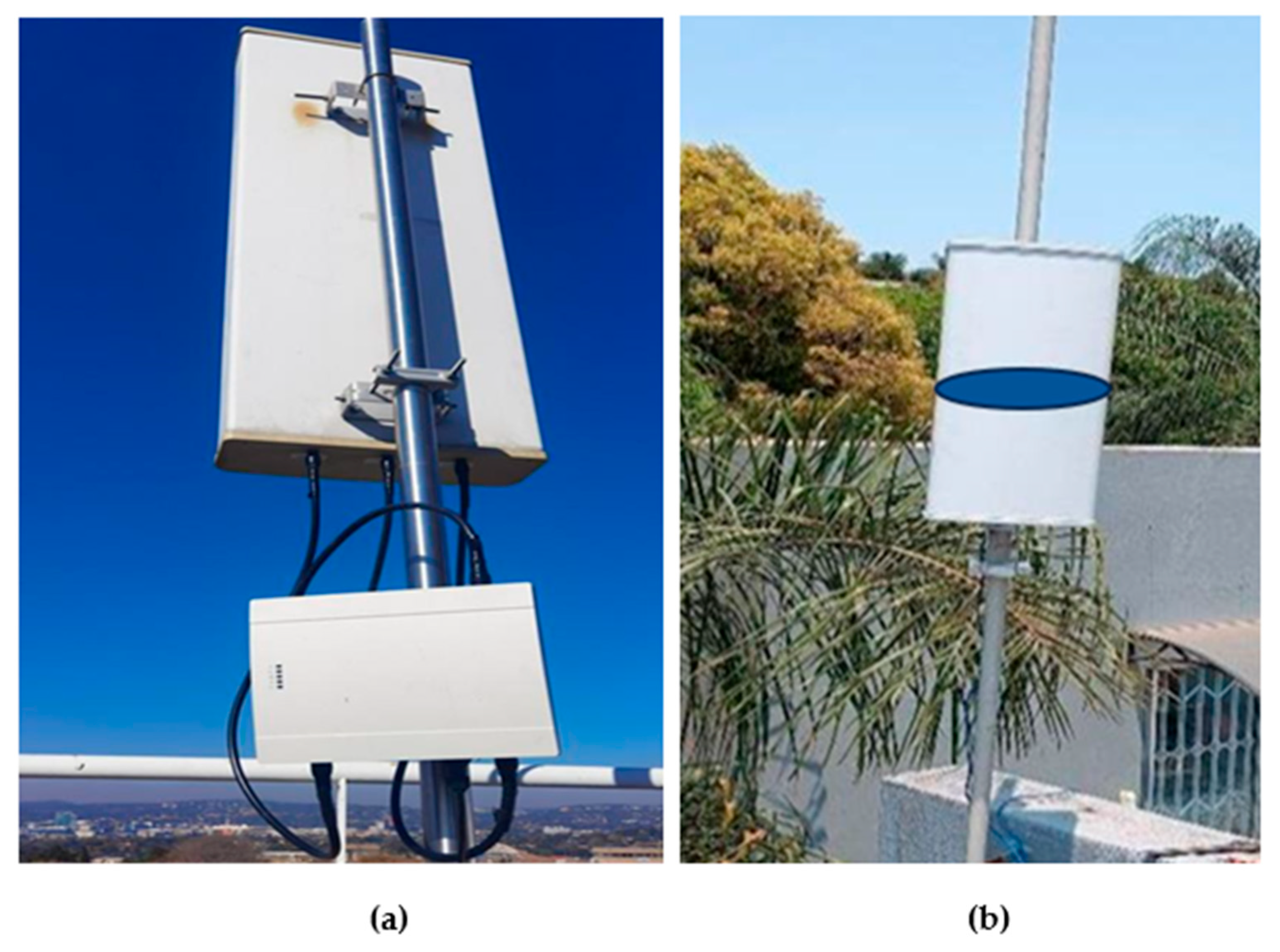
  • OEM 3: The WSDs from OEM 3 are based on the 3GPP LTE-A Standard [68,69]. Figure 4 depicts the Master WSD from OEM 3 deployed on the rooftop of building 43C at CSIR’s Scientia campus in Pretoria. Figure 4 also depicts the Client WSD from OEM 3 deployed at the rooftop of a residential house in Pretoria East.
As every manufacturer introduces its unique innovations and compromises, it is essential to perform a comparative assessment of the devices regarding performance in real-world scenarios and adherence to regulations.

3.2. Measurement Tools

The following measurement tools were used during the evaluation:
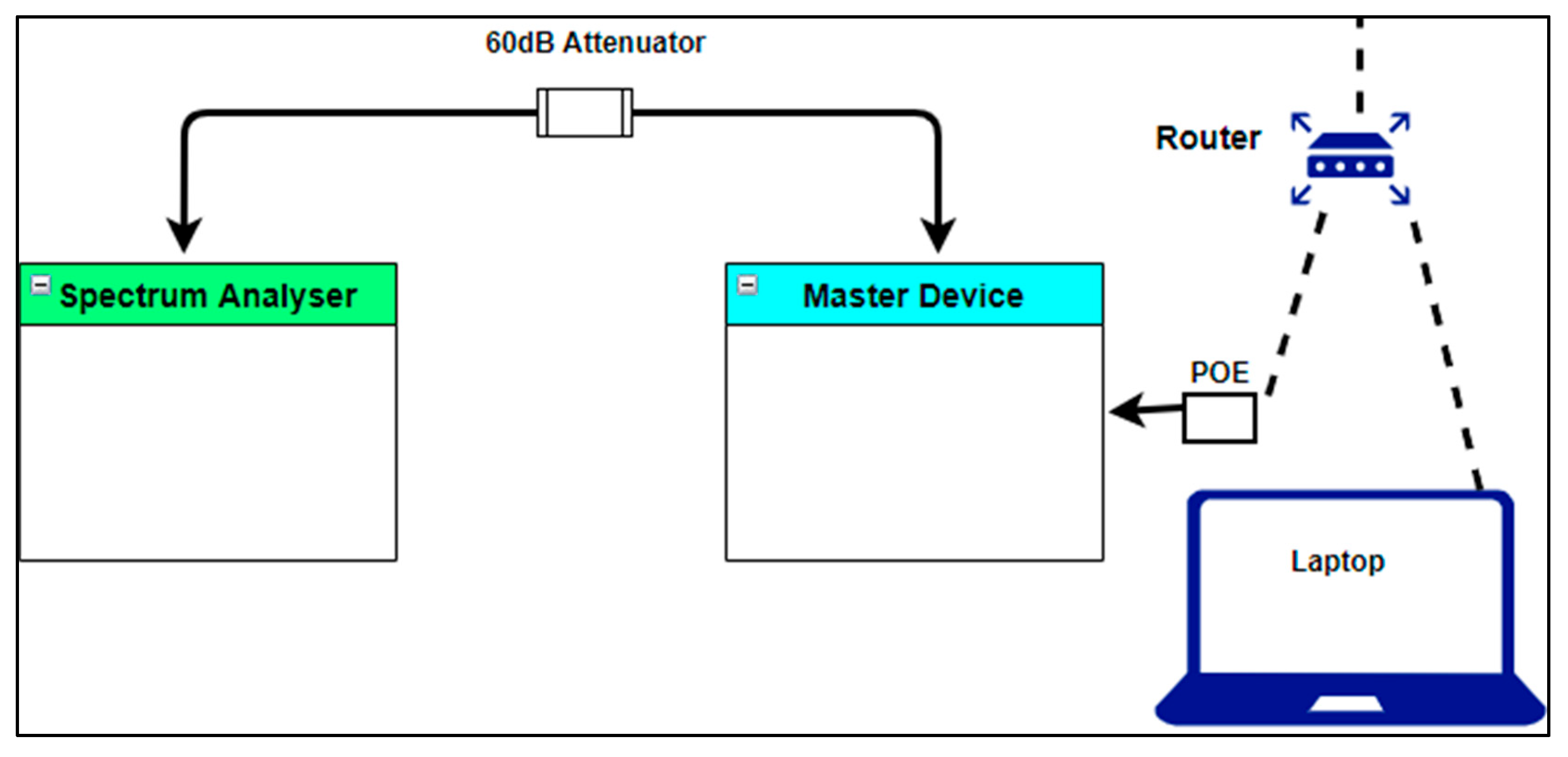
  • Rohde & Schwarz Spectrum Analyser Model FSH4 (100 kHz–3.6 GHz) (Munich, Germany): This tool was used to collect RSS measurements as well as the channel spectrum occupancy measurements during the experiment. As depicted in Figure 5, a 60 dB attenuator was used to reduce the power of the signal, to protect the spectrum analyser from any damage due to excessive RF input power exceeding the device’s maximum input tolerance. The laptop was used to configure a Master WSD.
  • LigoWave LinkCalc (Vilnius, Lithuania) [70]: This tool was used to perform radio propagation prediction and coverage analysis before deployment. It provided estimates of signal strength, path loss, and potential interference zones, helping to determine optimal antenna placement and ensure reliable communication links between the WSDs
  • iPerf [71]: This tool was installed on test devices to measure point-to-point transmission control protocol (TCP) and user datagram protocol (UDP) throughput between a Master and Client WSD. It enabled precise control over test parameters such as packet size, test duration and protocol, allowing for a detailed evaluation of network performance under controlled conditions.
  • Google/M Lab [72]: This cloud-based measurement platform was used to assess internet throughput and latency from the Client WSDs to remote test servers. It was used to evaluate real-world end-to-end performance, in terms of download/upload speed, and network responsiveness when accessing public internet services.
  • Ookla [73]: This tool was employed to validate internet performance metrics from various WSD locations. It provided user-friendly, widely recognised benchmarks for download/upload speeds and latency, complementing the more technical iPerf and M-Lab measurements with results comparable to real-world user experiences. These tests (like most tests using the previously mentioned tools) were repeated for several different Master and Client WSDs for Scenario 1 and 2, relative to the Master WSD antenna for each OEM. At each distance, the speed measurements were repeated five times, and the averages and standard deviations were estimated.
  • CSIR S-GLSD, also known as Spectrum Switch: In compliance with the South African TVWS regulatory framework, this system was used to dynamically assign the TVWS spectrum to the WSDs under test [27].

3.3. WSD Configuration Parameters

The following WSD configuration parameters were used during the experiments:
Master WSD Configuration: Table 2 provides an overview of the uniform configuration parameters used for Master WSDs from all three OEMs. It is important to note that specific parameters, such as MSC, antenna polarisation, and antenna type, could not be manually configured for OEM 3.
Client WSD Configuration: Table 3 provides an overview of the uniform configuration parameters used for the Client WSDs from all three OEMs. MSC was automatically configured on all WSDs, regardless of the OEM. The channel bandwidth was set to 8 MHz. Antenna configurations were nearly identical for the three OEMs. However, antenna polarisation and antenna type could not be changed for OEM 3, as the Master WSD uses a MIMO panel antenna and the CPE uses an integrated antenna. The antenna polarisation was configured to be horizontal for OEM 3 and vertical for both OEM 1 and OEM 2. The antenna height was configured as follows: 14 metres above ground level (AGL) for the Master WSD and 5.6 metres AGL for the Client WSDs in Scenario 1; and 14 metres AGL for the Master WSD and 8.5 metres AGL for the Client WSDs in Scenario 2. The WSDs automatically captured GPS coordinates, while the owner and operator details were manually configured.

4. Performance Evaluation

4.1. Received Signal Strength and Downlink Throughput

For both scenarios, the basic transmission loss was numerically predicted using the free space path loss (FSPL) model. The point-to-point (p-t-p) path loss was also calculated using the irregular terrain model (ITM) to account for terrain, climate, and clutter effects, utilising the LigoWave network planning tool (LinkCalc). These path losses were subsequently utilised to derive theoretical RSS and estimate the theoretical channel capacity via the Shannon–Hartley theorem. Finally, the predicted RSS and downlink throughput values were evaluated against the real-world measurement data from the WSD network to assess performance. The basic transmission losses were derived as follows:
L f b d B = 20   log 10 d + 20   log 10 f + 147.55
where
  • L b = the basic transmission loss (dB);
  • d = the distance between transmitter and receiver (m);
  • f = the frequency (Hz);
  • 147.55 = the constant for path loss in free space.
Subsequently, the RSS at the Client WSD was calculated as follows:
P r = P t x + G t x + G r L b
where
  • P r = the RSS (mW);
  • P t x = the transmit power (mW);
  • G t x = the transmit antenna gain (dBi);
  • G r = the received antenna gain (dBi);
  • L b = the basic transmission loss (dB).
The WSD total noise power was estimated as follows:
N P w s d = ( 174 + 10 × log B + N F w s d )
where
  • N P w s d = the WSD noise power (mW);
  • −174 = the WSD thermal noise density estimated at 290 K room temperature (dBm/Hz);
  • B = the system bandwidth (Hz);
  • N F w s d = the WSD noise figure (dB).
Next, we substituted into Equation (4) the RSS calculated in Equation (2), and the total noise power derived in Equation (3) was substituted to estimate the theoretical channel capacity using the Shannon–Hartley theorem as follows:
C = B log 2 ( 1 + 10 ( P r N w s d / 10 ) )
where
  • C = the channel capacity (Mbps);
  • B = the channel bandwidth (Hz);
  • P r = the received signal power (mW);
  • N P w s d = the WSD noise power (mW).
Ultimately, the theoretically predicted values were used in a linear domain, and the measurement obtained from the experiment was converted into a linear domain to evaluate the downlink throughput and RSS performance of the WSDs through the root mean squared error (RMSE) approach as follows:
R M S E = i 1 n ( m i p i ) 2 n
where
  • m i = the measured values at location i ;
  • p i = the predicted values at location i ;
  • n = the number of observation results.

4.2. Spectrum Utilisation Efficiency

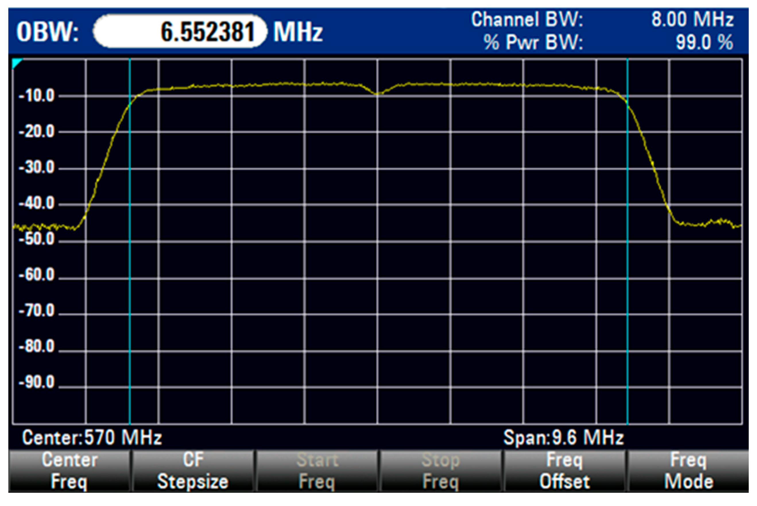
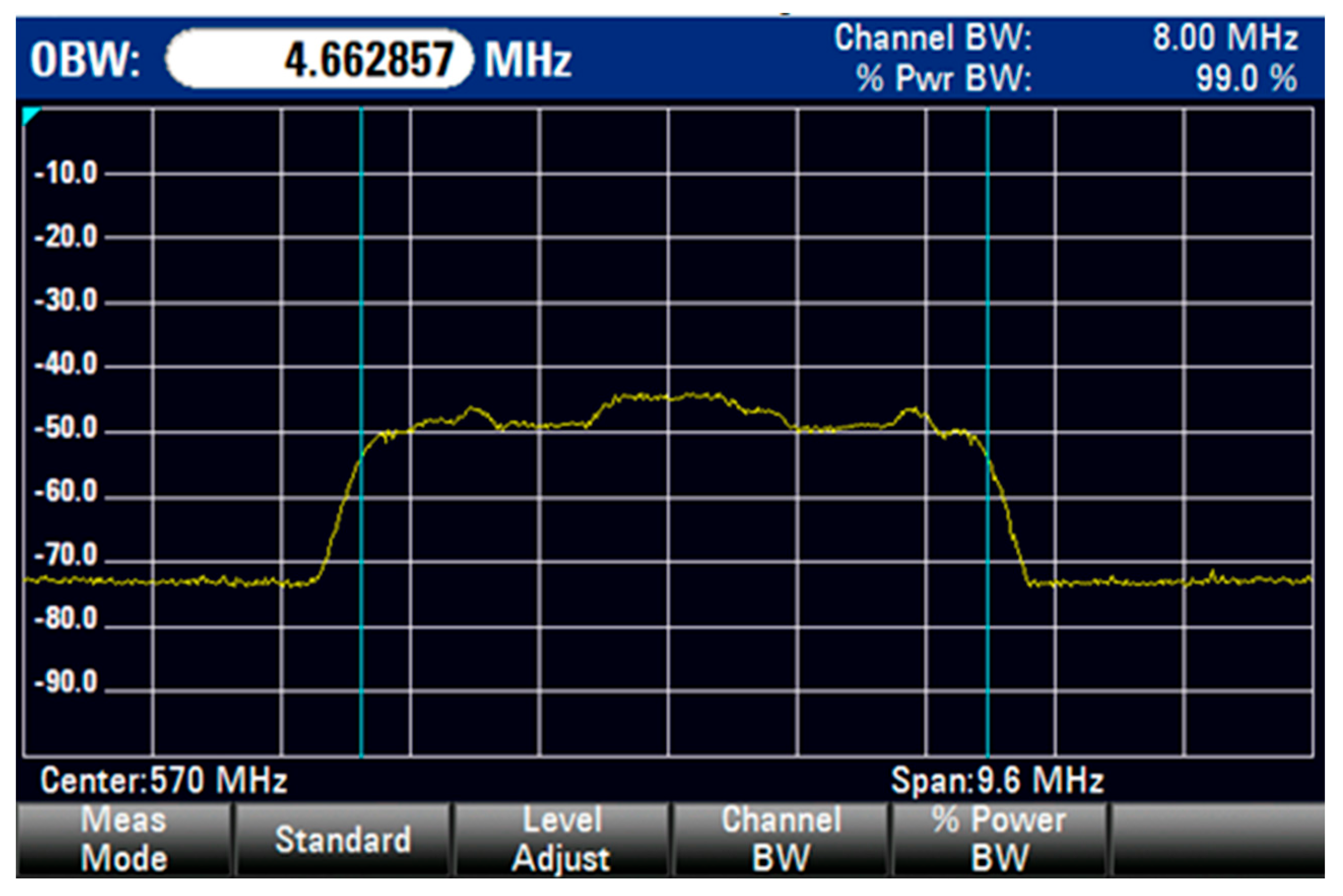
The Rohde & Schwarz Spectrum Analyser Model FSH4 was used to measure the occupied bandwidth (OBW) for each of the WSDs under test. However, only the OBW per single 8 MHz TVWS channel was measured, as only one WSD from OEM 3 supports channel bonding. Figure 6, Figure 7, and Figure 8 depict the measured OBW of each WSD.
The SUE for each WSD was calculated using the measured OBW and the TVWS channel bandwidth (CBW) values as follows:
S U E c h =   O B W C B W   × 100
where
  • S U E c h = the SUE per channel (%);
  • O B W = the occupied bandwidth in a single TVWS channel (MHz);
  • C B W = a single TVWS channel width (MHz).

5. Results and Discussion

5.1. Spectrum Utilisation Efficiency

The SUE performancefor all WSDs is presented in Table 4. The results show that OEM 1 and OEM 2 WSDs outperformed those of OEM 3, achieving a SUE of 81.9% in a single 8 MHz TVWS channel. This advantage may stem from the inherent design of the 802.11af PHY layer, which supports channel widths of 6, 8, and 12 MHz, whereas the 3GPP LTE-A PHY layer supports channel widths of 5, 8, 10, and 20 MHz. The efficiently utilised channels in 802.11af reduce spectrum underutilisation.

5.2. Scenario 1: Outdoor Short-Distance (RSS and Throughput Performance Metrics)

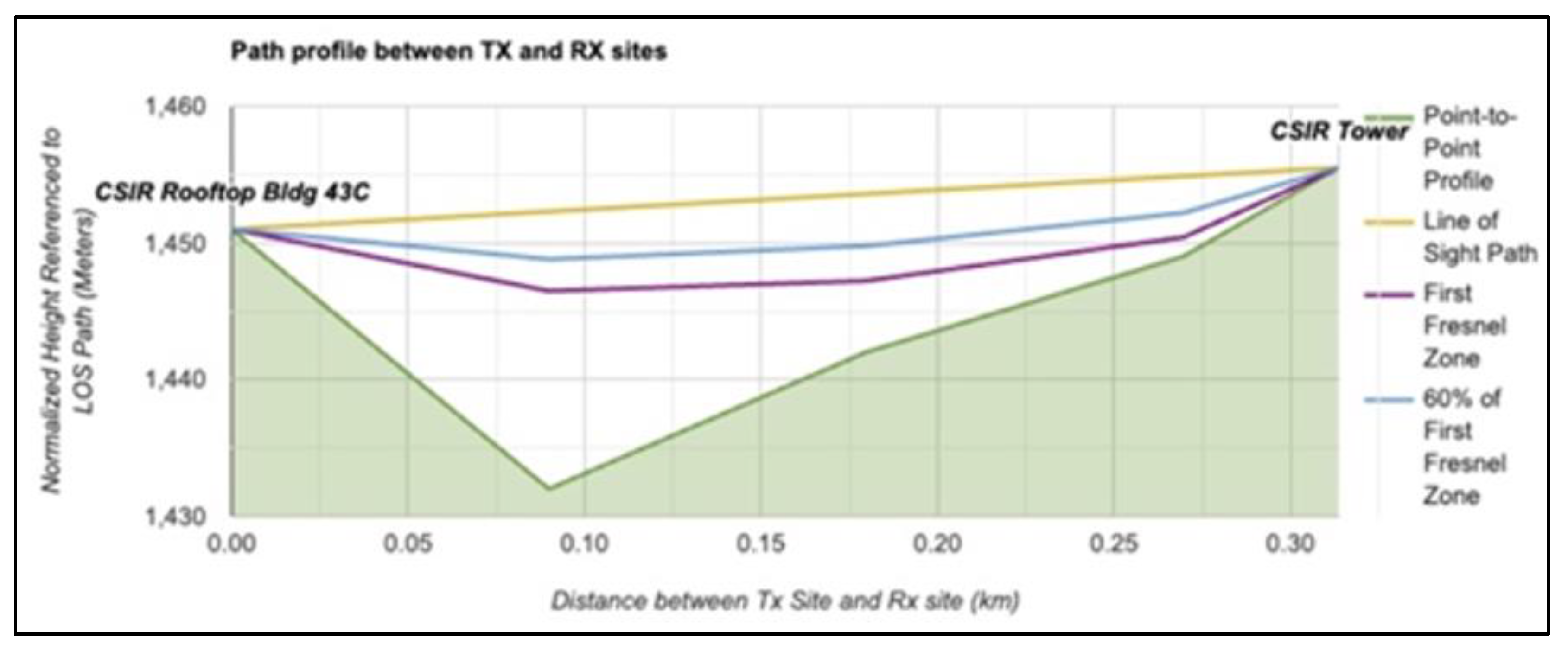
The Master WSD antennas were mounted on the rooftop of building 43C at CSIR’s Scientia campus in Pretoria, South Africa, at a height of 21 metres AGL. The Client WSDs were installed 300 metres away on a tower within the CSIR Scientia campus with an antenna height of 5.6 metres AGL. A line-of-sight (LoS) undulated propagation path between the two was observed with insignificant obstructions from a low-rise building and shrub vegetation, which had little impact on signal transmission. Figure 9 below depicts the p-t-p path profile for Scenario 1.
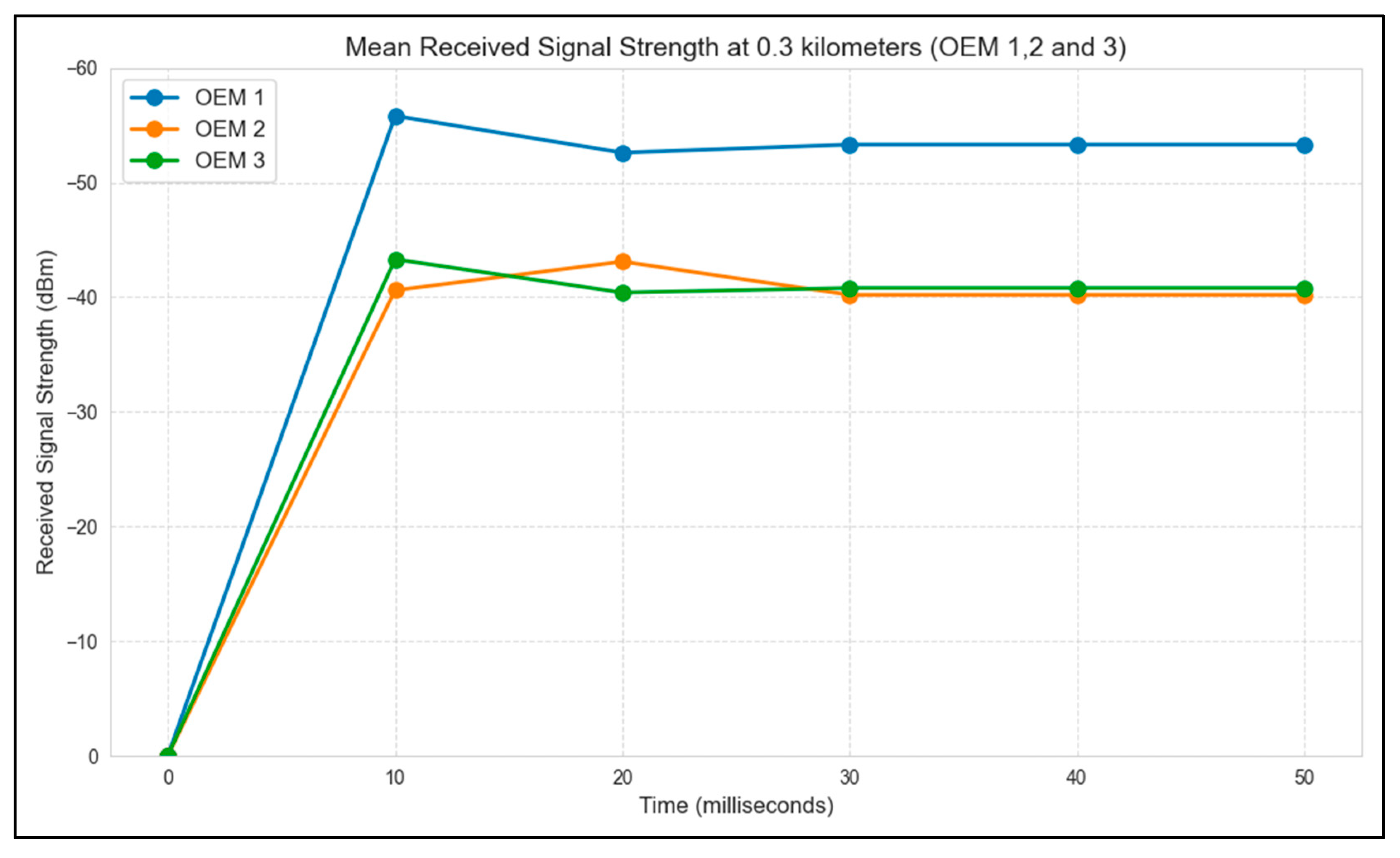
In this scenario, the derived RSS and downlink throughput performance metrics result for each WSD under test are summarised in Table 5, Table 6, Figure 10, and Figure 11. The WSDs from OEM 2 and OEM 3 demonstrate the best performance, with RSS measurements showing the lowest RMSE as depicted in Table 5 and Figure 10, while the WSD from OEM 1 showed the best performance on the downlink throughput metric, as depicted in Table 6 and Figure 11.

5.3. Scenario 2: Outdoor Long-Distance (RSS and Throughput) Performance Metrics

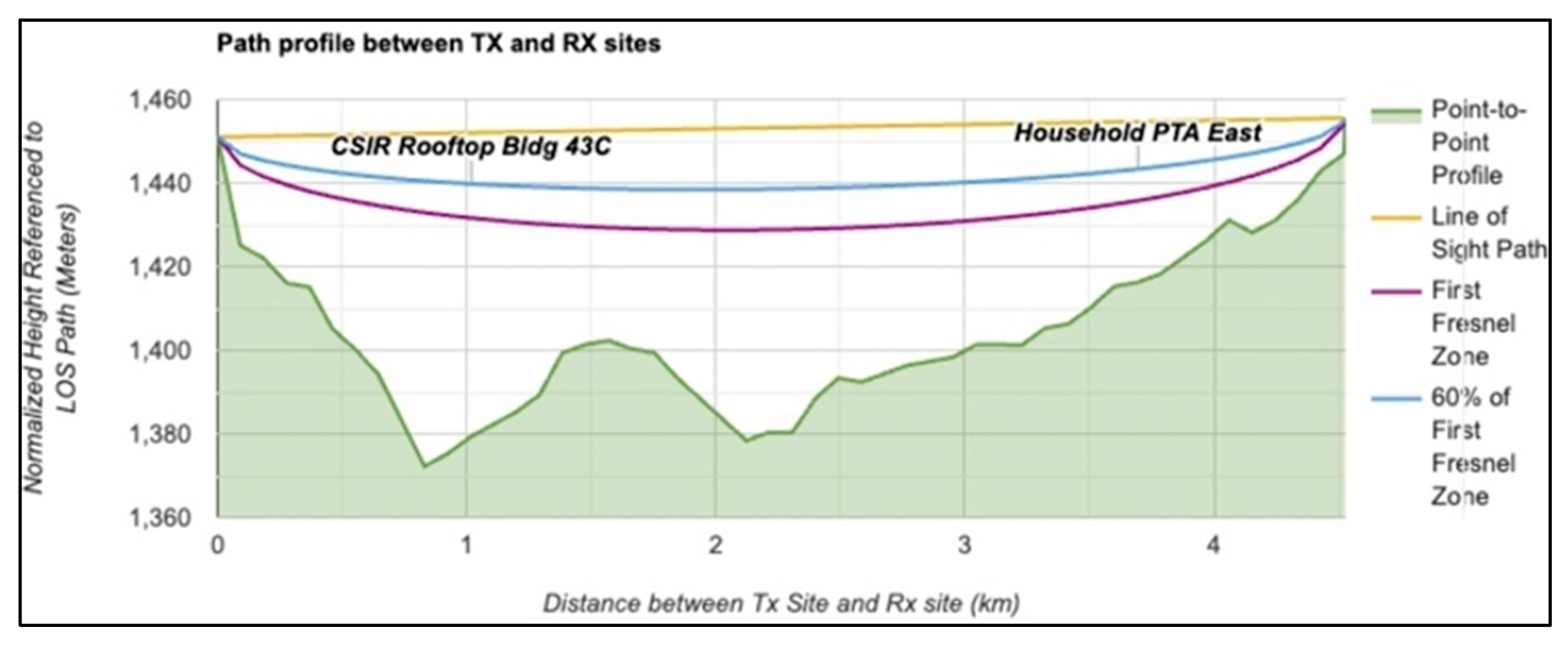
The Master WSD antennas were mounted on the rooftop of building 43C at CSIR’s Scientia campus in Pretoria, South Africa, at a height of 21 metres AGL. The Client WSDs were installed 4.5 kilometres away at the rooftop of a residential house in Pretoria East neighbourhood with an antenna height of 8.5 metres AGL. An LoS undulated propagation path was observed with insignificant obstructions from low-rise urban buildings and trees, which had little impact on signal transmission. Figure 12, depicts the p-t-p path profile for Scenario 2.
In this scenario, the RSS and downlink throughput performance metrics result for each WSD under test is summarised in Table 7, Table 8, Figure 13, and Figure 14. In the RSS metric, Table 7 WSDs from OEM 2 and OEM 3 demonstrated the best performance, with RSS measurements showing the lowest RMSE, closely matching predicted values as depicted in Table 7 and Figure 13. WSDs from OEM 2 and OEM 3 showed the best performance in the downlink throughput metric, as presented in Table 8 and Figure 14.
In general, mixed performance results from WSDs under test were observed in both scenarios of the experiment. While the WSDs based on the IEEE 802.11af Standard (OEM 1 and OEM 2) demonstrated the best performance on the downlink throughput metric in both scenarios (short-distance and long-distance), the WSD based on the 3GPP LTE-A Standard was consistently second-placed between the two WSDs based on the IEEE 802.11af Standard in both scenarios. The same is true for the RSS performance metric. The superior downlink throughput of IEEE 802.11af WSDs is likely due to their stronger performance on the SUE metric. Furthermore, compared to other WSDs, WSDs from OEM 2 exhibited an overall better RSS performance due to their Master WSD’s higher transmit power levels and the Client WSD’s higher receiver antenna gain, compared to other WSDs. It is important to note that the MSC parameters were set to ‘auto’ for all WSDs under test. This was to allow devices to automatically adjust to the best modulation and coding schemes during the experiments.

5.4. S-GLSD Connectivity

The South African TVWS regulatory framework requires WSDs to access the TVWS spectrum only through a certified S-GLSD provider. Furthermore, only the Master WSDs are permitted to communicate with the S-GLSD to acquire the spectrum, both for themselves and on behalf of their associated Client WSDs [16]. WSDs from the three OEMs were subjected to and passed the following test cases, in a procedural manner [74]. An overview of the tests that were performed follows:
  • S-GLSD Discovery: The Master WSD retrieves certified S-GLSD provider details (including PAWS URLs) from the R-GLSD web list. Discovery occurs at startup and refreshes periodically based on the ‘maxRefreshMinutes’ value in the response, ensuring up-to-date GLSD instance data.
  • S-GLSD Communication: The Master WSD initiates communication by sending an INIT request on startup or whenever the S-GLSD configurations have changed. It then registers itself (approval required before client registration). Registration is also triggered by provider/instance changes, ownership updates, or location shifts exceeding 100m (but not for location changes of less than 100m). The Master then requests operational parameters (OPs) for itself and clients. It refreshes them after registration, INIT, or expiry (24 h for fixed WSD or 12 h for nomadic WSD). Finally, the Master WSD notifies the S-GLSD of channel usage within 60 s of receiving OPs, prioritising its notification before that of the clients.
  • Cease Transmission: The Master WSD does not transmit if it cannot connect to the S-GLSD and its OPs are invalid. Similarly, Client WSDs only transmit after receiving a verification signal from the Master and with valid OPs. Both must cease transmission within 60 s (Master) or 10 s (Client) if channel usage notification or contact verification fails. If connectivity issues persist, transmission stops once OPs expire, ensuring compliance with validity periods.
  • Continuous Operation: During S-GLSD connectivity loss, WSDs are permitted to renew the OPs for an additional validity period automatically. Thus, fixed WSDs have an extended validity of up to 48 h in total, whereas nomadic WSDs have up to 24 h. Both Master and Client WSDs may continue operating post OPs expiry under these conditions. Furthermore, the WSDs are permitted to transmit whenever S-GLSD discovery fails, but existing OPs remain valid (including those with extended validity). On startup, both WSD types continue transmitting if their current OPs are still valid, ensuring uninterrupted service while remaining compliant with validity periods.
  • Ruleset Configuration: WSDs dynamically adapt to user configurations, including S-GLSD provider/instance choice, API security (API Key/Bearer Token), ownership details, and antenna characteristics. The Master WSD auto-configures its location via internal/external GPS. Optional regulatory or proprietary settings can also be configured for flexible operation.
Figure 15, depicts the CSIR’s Spectrum Switch graphical user interface (GUI) used during the experiments to track the communication between the Master WSDs and the S-GLSD.

6. Conclusions

Access to the TVWS spectrum presents an excellent opportunity to bridge the digital divide, particularly in rural and remote areas, using DSA techniques. Several OEMs are already producing radio equipment that incorporates the DSA techniques for the TVWS spectrum. This paper presents a performance evaluation of WSDs from three OEMs. The WSDs are based on two distinct standards: IEEE 802.11af and 3GPP LTE-A. The WSD performance was evaluated based on three metrics – SUE, downlink throughput, and RSS – in two deployment scenarios: short and long distances.
The results serve as a form of feedback to inform OEM stakeholders about areas that need improvement to enhance WSD performance, particularly in the PHY layer. Such advancements will strengthen wireless ecosystems as DSA becomes pivotal beyond the TVWS spectrum, such as in the Citizen Band Radio Service (CBRS) in the USA and DSA for spectrum sharing in the S and C bands that are currently being considered by ICASA in South Africa.
Furthermore, this paper has highlighted that DSA regulations, such as those for TVWS, are intentionally technology-agnostic. No regulatory body mandates the use of specific radio access technologies (RATs) or standards but promotes flexibility in adherence to the technical ruleset. This flexibility is essential for improving SUE and spurring technological innovations; however, it has often been misunderstood within the connectivity ecosystem, creating unnecessary confusion about permissible implementations.

Author Contributions

Conceptualization, M.V., K.M., L.N., L.M. and M.M.; methodology, M.V., K.M., L.N., L.M. and M.M.; software, M.V., K.M., L.N. and L.M.; validation, M.V., L.M. and M.M.; formal analysis, M.V., K.M. and L.N.; writing—original draft preparation, M.V., K.M., L.N. and L.M.; writing—review and editing, M.V., L.N., L.M. and M.M.; supervision, All authors have read and agreed to the published version of the manuscript.

Funding

This research received no external funding.

Institutional Review Board Statement

Not applicable.

Informed Consent Statement

Not applicable.

Data Availability Statement

The data presented in this manuscript are exclusively obtained from empirical testing of actual radio systems. No instances of data plagiarism or fabrication are present. Due to confidentiality obligations, we are unable to disclose additional data or methodological details at this stage.

Conflicts of Interest

The authors declare no conflicts of interest.

References

  1. Elshafie, H.; Fisal, N.; Abbas, M.; Hassan, W.A.; Mohamad, H.; Ramli, N.; Jayavalan, S.; Zubair, S. A survey of cognitive radio and TV white spaces in Malaysia. Trans. Emerg. Telecommun. Technol. 2014, 26, 975–991. [Google Scholar] [CrossRef]
  2. Anabi, K.H.; Nordin, R.; Abdullah, N.F. Database-Assisted Television White Space Technology: Challenges, Trends and Future Research Directions. IEEE Access 2016, 4, 8162–8183. [Google Scholar] [CrossRef]
  3. ICASA. Radio Frequency Spectrum Assignment Plan for the 470 to 694 MHz Frequency Band. Available online: https://www.icasa.org.za/news/2020/radio-frequency-spectrum-assignment-plan-for-the-470-to-694-mhz-frequency-band (accessed on 21 August 2025).
  4. Moshe, T.M.; Makgotlho, R.; Mekuria, F. Setting the Scene for TV White Spaces and Dynamic Spectrum Access in South Africa. In Proceedings of the IST-Africa 2012 Conference, Dar es Salaam, Tanzania, 9–11 May 2012. [Google Scholar]
  5. Kruger, A. The Power of Wireless Internet in Rural Areas: A Game-Changer for South Africa. Available online: https://adnotes.co.za/the-power-of-wireless-internet-in-rural-areas-a-game-changer-for-south-africa/ (accessed on 21 August 2025).
  6. Lysko, A.A.; Masonta, M.T.; Johnson, D.L. The Television White Space Opportunity in Southern Africa: From Field Measurements to Quantifying White Spaces. In White Space Communication; Spinger: Berlin/Heidelberg, Germany, 2014. [Google Scholar] [CrossRef]
  7. Mthethwa, N.; Sebopetse, N.; Vilakazi, M.; Mfupe, L.; Mofolo, M.; Mekuria, F. Sustainable Internet4All in South African Rural and Township Communities. In Proceedings of the 2023 IEEE Africon, Nairobi, Kenya, 20–22 September 2023; pp. 1–6. [Google Scholar] [CrossRef]
  8. Ramoroka, M.T.; Masonta, M.T.; Kliks, A. TV White Space Networks Deployment: A Case Study of Mankweng Township in South Africa. In e-Infrastructure and e-Services; Springer: Cham, The Netherlands, 2016; Volume 171, pp. 3–13. [Google Scholar] [CrossRef]
  9. Lysko, A.A.; Masonta, M.T.; Mofolo, M.R.; Mfupe, L.; Montsi, L.; Johnson, D.L.; Mekuria, F.; Ngwenya, D.W.; Ntlatlapa, N.S.; Hart, A.; et al. First Large TV White Spaces Trial in South Africa: A Brief Overview. In Proceedings of the 2014 6th International Congress on Ultra Modern Telecommunications and Control Systems and Workshops (ICUMT), St. Petersburg, Russia, 6–8 October 2014. [Google Scholar] [CrossRef]
  10. Mfupe, L.; Mekuria, F.; Mzyece, M. Geo-location White Space Spectrum Database: Models and Design of South Africa’s First Dynamic Spectrum Access Coexistence Manager. KSII Trans. Internet Inf. Syst. 2014, 8, 3810–3836. [Google Scholar] [CrossRef]
  11. Masonta, M.T.; Ramoroka, T.M.; Lysko, A.A. Using TV White Spaces and e-Learning in South African rural schools. In Proceedings of the 2015 IST-Africa Conference, Lilongwe, Malawi, 6–8 May 2015; pp. 1–12. [Google Scholar] [CrossRef]
  12. Masonta, M.T.; Kola, L.M.; Lysko, A.A.; Pieterse, L.; Velempini, M. Network Performance Analysis of the Limpopo TV White Space (TVWS) Trial Network. In Proceedings of the AFRICON 2015, Addis Ababa, Ethiopia, 14–17 September 2015. [Google Scholar] [CrossRef]
  13. Kaliappan, E.; Madhevan, P.R.; Ram, A.S.A.; Ponkarthika, B.; Abinesh, M.R. Remote Surveillance and Communication Using Television White Space. In Innovative Data Communication Technologies and Application; Springer: Singapore, 2021. [Google Scholar] [CrossRef]
  14. Mfupe, L.; Dzinotyiweyi, C.; Pillay, K. Rural TVWS Network Operators Support Programme. In Final Impact Report-Phase II.; Council for Scientific and Industrial Research (CSIR): Pretoria, South Africa, 2024; Available online: https://heyzine.com/flip-book/13ceb871f5.html (accessed on 24 July 2024).
  15. Hussein, H.M.; Katzis, K.; Mfupe, L.P.; Bekele, E.T. Performance Optimization of High-Altitude Platform Wireless Communication Network Exploiting TVWS Spectrums Based On Modified PSO. IEEE Open J. Veh. Technol. 2022, 3, 1–11. [Google Scholar] [CrossRef]
  16. Independent Communication Authority of South Africa. Electronic Communication Act, 2005 (Act no. 36 of 2005): Regulations on the Use of Television White Spaces (Notice 147 of 2018), 23 March 2018. Available online: https://www.icasa.org.za/legislation-and-regulations/regulations-on-the-use-of-television-white-spaces-2018 (accessed on 30 August 2025).
  17. Lamola, M.M.; Johnson, D.; Lysko, A.A.; Zlobinsky, N. TVWS Devices Spectrum Mask Test and Analysis. In Proceedings of the 2016 Southern African Telecommunications Networks and Applications Conference (SATNAC), Western Cape, South Africa, 4–7 September 2016. [Google Scholar]
  18. Toheeb, O. TV White Space Technology and Its Use in Rural Broadband. 2025. Available online: https://www.researchgate.net/publication/392662880_TV_White_Space_Technology_and_Its_Use_in_Rural_Broadband (accessed on 5 June 2025).
  19. Federal Communications Commission (FCC). Cable Television, FCC Media Engineering. Available online: https://www.fcc.gov/media/engineering/cable-television (accessed on 21 August 2025).
  20. Nyasulu, T.; Crawford, D.H.; Mikekaa, C. Malawi’s TV white space regulations: A review and comparison with FCC and Ofcom regulations. In Proceedings of the 2018 IEEE Wireless Communications and Networking Conference (WCNC), Barcelona, Spain, 15–18 April 2018; pp. 1–6. [Google Scholar] [CrossRef]
  21. Noguet, D.; Gautier, M.; Berg, V. Advances in opportunistic radio technologies for TVWS. EURASIP J. Wirel. Commun. Netw. 2011, 2011, 1–12. [Google Scholar] [CrossRef]
  22. Holland, O.; Sastry, N.; Ping, S.; Knopp, R.; Kaltenberger, F.; Nussbaum, D.; Hallio, J.; Jakobsson, M.; Auranen, J.; Ekman, R.; et al. A series of trials in the UK as part of the Ofcom TV white spaces pilot. In Proceedings of the 2014 1st International Workshop on Cognitive Cellular Systems (CCS), Duisburg, Germany, 2–4 September 2014; pp. 1–5. [Google Scholar] [CrossRef]
  23. Infocomm Media Development Authority (IMDA). TV White Space, IMDA. Available online: https://www.imda.gov.sg/regulations-and-licensing-listing/spectrum-management/spectrum-planning/tv-white-space (accessed on 21 August 2025).
  24. Calinao, H.A.; Jr, L.M.; Takada, J.; Trinidad, E.; Homma, K.; Ota, K.; Mazlan, S.A.; Rambat, S. Development of a Material for Gauging Sustainable Transitions Towards Adoption and Implementation of Television White Space Communications Systems. Int. J. Emerg. Technol. Adv. Eng. 2021, 11, 39–57. [Google Scholar] [CrossRef] [PubMed]
  25. EN 301 598 V1.1.1; White Space Devices (WSD); Wireless Access Systems Operating in the TV Broadcast White Spaces; Harmonized EN Covering the Essential Requirements of Article 3.2 of the R&TTE Directive. ETSI: Valbonne, France, 2014.
  26. EN 62368-1; Audio/Video, Information and Communication Technology Equipment—Safety Requirements. CENELEC: Brussels, Belgium, 2020.
  27. Council for Scientific and Industrial Research. About: The S-GLSD, 25 November 2024. Available online: https://whitespaces.csir.co.za/public/about (accessed on 30 August 2025).
  28. CISPR 32; Electromagnetic Compatibility of Multimedia Equipment —Emission Requirements. International Electrotechnical Commission (IEC): Geneva, Switzerland, 2015.
  29. EN 301 489-1; ElectroMagnetic Compatibility (EMC) Standard for Radio Equipment and Services; Part 1: Common Technical Requirements. European Telecommunications Standards Institute (ETSI): Sophia Antipolis Cedex, France, 2019.
  30. IEC 60950-1; Information Technology Equipment —Safety —Part 1: General Requirements. IEC: Geneva, Switzerland, 2005.
  31. IEC 62368-1; Audio/Video, Information and Communication Technology Equipment —Part 1: Safety Requirements. IEC: Geneva, Switzerland, 2023.
  32. Rahman, M.; Saifullah, A. A comprehensive survey on networking over TV white spaces. Pervasive Mob. Comput. 2019, 59, 1–30. [Google Scholar] [CrossRef]
  33. Zhang, W.; Yang, J.; Zhang, G.; Yang, L.; Yeo, C.K. TV white space and its applications in future wireless networks and communications: A survey. IET Commun. 2018, 12, 2521–2532. [Google Scholar] [CrossRef]
  34. Zeng, Y.; Liang, Y.C.; Lei, Z.; Oh, S.W.; Chin, F.; Sun, S. Worldwide Regulatory and Standardization Activities o Cognitive Radio. In Proceedings of the 2010 IEEE Symposium on New Frontiers in Dynamic Spectrum (DySPAN), Singapore, 6–9 April 2010; pp. 1–9. [Google Scholar]
  35. OFCOM. Ofcom Progresses with New Wireless Technology. Available online: https://www.medialaws.eu/uk-ofcom-progresses-with-new-wireless-technology/ (accessed on 2 September 2011).
  36. ETSI EN 301 489; (Series Overview): “ElectroMagnetic Compatibility (EMC) Standard for Radio Equipment and Services.”. ETSI: Sophia Antipolis Cedex, France.
  37. EN 301 489-17; ElectroMagnetic Compatibility (EMC) Standard for Radio Equipment; Part 17: Specific Conditions for 2.4 GHz Wide-Band Transmission Systems, 5 GHz High-Performance RLAN Equipment and 5.8 GHz Broadband Data Transmitting Systems. ETSI: Sophia Antipolis Cedex, France.
  38. BS EN IEC 62368-1:2024+A11:2024; Audio/Video, Information and Communication Technology Equipment—Safety Requirements. British Standards Institution: London, UK, 2024.
  39. Leong, S.; Lee, T. Internet Governance: Singapore’s Regulatory Influence. In Global Internet Governance: Influences from Malaysia and Singapore; Springer: Singapore, 2020; pp. 71–90. [Google Scholar]
  40. Haenig, M.A.; Ji, X. A tale of two Southeast Asian states: Media governance and authoritarian regim10.es in Singapore and Vietnam. Asian Rev. Political Econ. 2024, 3, 4. [Google Scholar] [CrossRef]
  41. Ante, M.G.; Molina, J.A.; Trinidad, E.; Materum, L. A survey and comparison of TV white space implementations in Japan, the Philippines, Singapore, the United Kingdom, and the United States. Int. J. Adv. Technol. Eng. Explor. 2021, 8, 780. [Google Scholar] [CrossRef]
  42. Directive 2014/53/EU; (Radio Equipment Directive, RED). European Union, Official Journal of the European Union: Luxembourg, 2014.
  43. European Parliament and Council. Directive 2014/53/EU on the Harmonisation of the Laws of the Member States Relating to the Making Available on the Market of Radio Equipment (Radio Equipment Directive); Publications Office of the European Union: Luxembourg, 2014. [Google Scholar]
  44. Bañacia, A.S.; Ferolin, R.J.; Sawada, H.; Ishizu, K.; Ibuka, K.; Matsumura, T.; Kojima, F. Coexistence of a Low-power IEEE 802.11 af Secondary User in TV White Space with Analog and Digital TV systems. In Proceedings of the 2021 24th International Symposium on Wireless Personal Multimedia Communications (WPMC), Okayama, Japan, 14–16 December 2021; pp. 1–6. [Google Scholar]
  45. Foo, Y.L. Harmonious Coexistence of IEEE 802.11 af Wireless LAN and Digital TV. IETE Tech. Rev. 2021, 38, 239–244. [Google Scholar] [CrossRef]
  46. Reddy, V.A.; Stüber, G.L. Implementation of the IEEE 802.11 af standard on ns-3. In Proceedings of the 2018 Workshop on NS-3 (WNS3 2018), Mangalore, India, 13–14 June 2018. [Google Scholar]
  47. Vithanawasam, C.K. Design and Analysis of TVWS Antenna for Rural Wireless Connectivity. Doctoral Dissertation, Swinburne University of Technology, Kuching, Malaysia, 2021. [Google Scholar]
  48. Dixit, S.; Dutta, A.; Agrawal, S.; Olivas, M.A.; Bhatia, V.; Carrillo, C.D.A.; Jha, P.; Jabhera, M.; Karna, A.; Khanganba, S.P.; et al. Connecting the unconnected. In Proceedings of the 2023 IEEE Future Networks World Forum (FNWF), Baltimore, MD, USA, 13–15 November 2023; pp. 1–88. [Google Scholar]
  49. Oluwafemi, I.B.; Bamisaye, A.P.; Faluru, M.A. Quantitative estimation of TV white space in Southwest Nigeria. Telecommun. Comput. Electron. Control 2021, 19, 36–43. [Google Scholar] [CrossRef]
  50. Ismail, M.; Kissaka, M.; Mafole, P. Capacity Analysis of a Television White Space Network Deployed under Distance Distribution Approach. Tanzan. J. Sci. 2021, 47, 214–227. [Google Scholar]
  51. Mei, R.; Wang, Z. Multi-Agent Deep Reinforcement Learning-Based Resource Allocation for Cognitive Radio Networks. IEEE Trans. Veh. Technol. 2024, 74, 4744–4757. [Google Scholar] [CrossRef]
  52. Saghir, M.H. Spectrum Allocation Strategies for Future Wireless Networks. Master’s Thesis, Chalmers University of Technology, Gothenburg, Sweden, 2015. [Google Scholar]
  53. Lysko, A.A. Work in television white spaces (TVWS) and dynamic spectrum and a bit on antennas. In Proceedings of the South African IEEE Joint AP/MTT/EMC Chapter Conference 2016, Stellenbosch, South Africa, 28–19 July 2016. [Google Scholar]
  54. Espinosa, M.; Perez, M.; Zona, T.; Lagrange, X. Radio Access Mechanism for Massive Internet of Things Services Over White Spaces. IEEE Access 2021, 9, 120911–120923. [Google Scholar] [CrossRef]
  55. Buitrago, M.E. Cognitive Radio Architecture for Massive Internet of Things services with Dynamic Spectrum Access. Ph.D. Thesis, Universitat Politècnica de València, Valencia, Spain, 2021. [Google Scholar]
  56. Guimarães, D.A. Spectrum Hole Geolocation for Database-Driven IoT-Enabled Dynamic Spectrum Access. IEEE Access 2025, 13, 64199–64215. [Google Scholar] [CrossRef]
  57. Buddhikot, M.M. Understanding dynamic spectrum access: Models, taxonomy and challenges. In Proceedings of the 2007 2nd IEEE International Symposium on New Frontiers in Dynamic Spectrum Access Networks, Dublin, Ireland, 17–20 April 2007; pp. 649–663. [Google Scholar]
  58. Microsoft Research. Microsoft’s White Space Trial in North Carolina. 2011. Available online: https://www.microsoft.com/en-us/research/project/dynamic-spectrum-and-tv-white-spaces/ (accessed on 27 September 2010).
  59. Ofcom. TV White Spaces Pilot: Trial Evaluation Report, UK. 2015. Available online: https://www.ofcom.org.uk (accessed on 12 February 2012).
  60. Lopez-Benitez, M.; Casadevall, F. Spectrum usage models for the analysis, design and simulation of cognitive radio networks. EURASIP J. Wirel. Commun. Netw. 2012, 2012, 273. [Google Scholar]
  61. Infocomm Media Development Authority. TV White Space Trials in Singapore, IMDA. 2016. Available online: https://www.imda.gov.sg (accessed on 23 May 2017).
  62. Masonta, M.T.; Kliks, A.; Mzyece, M. Television White Space (TVWS) Access Framework for Developing Regions. In Proceedings of the IEEE Africon 2013 Workshop: Cognitive radio and Opportunistic TVWS Broadband Wireless Networks for broadband internet provision in Emerging Economies, Mauritius, South Africa, 9–12 September 2013. [Google Scholar]
  63. Innonet. Service Construction. Available online: https://innonet.net:49248/eng/html/service_construction.php (accessed on 21 August 2025).
  64. Innonet. Product Detail. Available online: https://innonet.net:49248/eng/html/product_detail.php?pid=1 (accessed on 21 August 2025).
  65. NZIA. About Us. Available online: https://www.nzia.kr/about-us (accessed on 21 August 2025).
  66. NZIA. Whitepaper (v1). Available online: https://www.nzia.kr/_files/ugd/21ad4e_69b23aa3789c4d3096e95d309d73cf4e.pdf (accessed on 21 August 2025).
  67. NZIA. Whitepaper (v2). Available online: https://www.nzia.kr/_files/ugd/21ad4e_17af55fe91494c19a13a3fbee9175111.pdf (accessed on 21 August 2025).
  68. WiFrost. Products. Available online: https://www.wifrost.com/product (accessed on 21 August 2025).
  69. WiFrost. WiFrost Starter Guide. Available online: https://wifrost.notion.site/WiFrost-Starter-Guide-bffc94b2be7548148ed624f6d7361cbd (accessed on 21 August 2025).
  70. Ramirez, S.; Jiménez, F.; Reynoso, W.E.C.; Alcantara, E. Implementation WiMAX Stations. In Proceedings of the 13th Latin American and Caribbean Conference for Engineering and Technology: Engineering Education Facing the Grand Challenges, What Are We Doing? Santo Domingo, Dominican Republic, 29–31 July 2015. [Google Scholar] [CrossRef]
  71. Zieliński, B. Assessment of iPerf as a Tool for LAN Throughput Prediction. Int. J. Electron. Telecommun. 2023, 69, 523–528. [Google Scholar] [CrossRef]
  72. Feamster, N. Measuring internet speed: Current challenges and future recommendations. Commun. ACM 2020, 63, 72–80. [Google Scholar] [CrossRef]
  73. MacMillan, K.; Mangla, T.; Saxon, J.; Marwell, N.P.; Feamster, N. A Comparative Analysis of Ookla Speedtest and Measurement Labs Network Diagnostic Test (NDT7). ACM SIGMETRICS Perform. Eval. Rev. 2023, 51, 41–42. [Google Scholar] [CrossRef]
  74. CSIR Whitespaces. TVWS Device Ruleset Test Cases. Available online: https://whitespaces.csir.co.za/public/guideline/document/49/TVWS_Device_Ruleset_Test_Cases.pdf (accessed on 21 August 2025).
Figure 1. An overview of the experimental setup for Scenario 1.
Applsci 15 09977 g001
Figure 2. An overview of the experimental setup for Scenario 2.
Applsci 15 09977 g002
Figure 3. (a) An overview of the OEM 1’s WSD (dual Master/Client WSD); (b) an overview of the OEM 2’s Master WSDs.
Applsci 15 09977 g003
Figure 4. (a) An overview of the OEM 3’s Master WSD/LTE-A eNodeB (below) and panel antenna (above); (b) an overview of the OEM 3’s Client WSDs with an integrated antenna.
Applsci 15 09977 g004
Figure 5. The setup that was used to measure RSS and spectrum occupancy.
Applsci 15 09977 g005
Figure 6. OEM 1’s Master WSD occupied bandwidth.
Applsci 15 09977 g006
Figure 7. OEM 2’s Master WSD occupied bandwidth.
Applsci 15 09977 g007
Figure 8. OEM 3’s Master WSD occupied bandwidth.
Applsci 15 09977 g008
Figure 9. Radio propagation link path profile for Scenario 1, which also shows the terrain and clutter profile between the transmitter and receiver sites.
Applsci 15 09977 g009
Figure 10. Mean received signal strength RSS over time, captured using Rohde & Schwarz Spectrum Analyser Model FSH4 at the antenna of Client WSDs under test from OEMs 1, 2, and 3 located 300 metres away from the Master WSDs. The results indicate that WSDs from OEM 2 and OEM 3 achieve the best RSS performance.
Applsci 15 09977 g010
Figure 11. Mean downlink throughputs over time, captured using iPerf, Google/M-Lab and Ookla at the Client WSDs under test from OEMs 1, 2, and 3 located 300 metres away from the Master WSDs. The results indicate that WSD from OEM1 achieves the best performance.
Applsci 15 09977 g011
Figure 12. Radio propagation link path profile for Scenario 2, which also shows the terrain and clutter profile between the transmitter and receiver sites.
Applsci 15 09977 g012
Figure 13. Mean RSS over time, captured using Rohde & Schwarz Spectrum Analyser Model FSH4 at the antenna of Client WSDs under test from OEMs 1, 2, and 3 located 4500 metres away from the Master WSDs. The results indicate that WSDs from OEMs 2 and 3 achieve the best RSS performance.
Applsci 15 09977 g013
Figure 14. Mean downlink throughputs over time, captured using iPerf, Google/M-Lab, and Ookla at the Client WSDs under test from OEMs 1, 2, and 3 located 4500 metres away from the Master WSDs. The results indicate the best performance that WSDs from OEMs 2 and 3 achieve the best performance.
Applsci 15 09977 g014
Figure 15. GUI of the CSIR’s S-GLSD/Spectrum Switch used during the experiments for the S-GLSD connectivity performance metric.
Applsci 15 09977 g015
Table 1. Technical specification of WSDs under test, for the three OEMs.
WSD
OEM 1OEM 2OEM 3
Tx Power EIRP (dBm)27 +/− 2 dB35Master: 36
Client: 33
Duplex ModeTDDTDDTDD, FDD
Frequency Range (MHz)470–698470–698470–698
Receiver Sensitivity (dBm)−98−98−104
Average Receiver Noise Figure (dB)555
Channel Bandwidth (MHz)6, 8, 126, 7, 85, 6, 8, 10, 20
Career AggregationNoNoYes
Wireless Standard802.11af802.11af3GPP LTE-A
Modulation Scheme and Coding (MSC)BPSK, QPSK, QAM 16, 64, 256BPSK, QAM 16, 64QPSK, QAM 16, 64, 256
WaveformOFDMOFDMOFDMA
GPSYesYesYes
PAWS RFC 7545YesYesYes
AntennaSISOSISOMIMO 2 × 2
NetworkEthernet, IPv4/IPv6Ethernet, IPv4/IPv6Ethernet, IPv4/IPv6
Software Version3.10.144.14.61LT100B_2.1.2489.1047
Table 2. Master WSD configuration parameters.
Master Device
OEM 1OEM 2OEM 3
Tx Power EIRP (dBm)28 3333
TVWS Channel Number/Frequency (MHz)33 (570)33 (570)33 (570)
Antenna Gain (dBi)61310
MSCautoautoauto
Channel Bandwidth (MHz)888
Antenna PolarisationVerticalVerticalHorizontal
Antenna Height (m)141414
Antenna TypeYagiYagiPanel Directional
Table 3. Client WSD configuration parameters.
Client Device
OEM 1OEM 2OEM 3
Tx Power EIRP (dBm)283333
Antenna Gain (dBi)51010
MSCAutoAutoAuto
Channel Bandwidth (MHz)888
Antenna PolarisationVerticalVerticalHorizontal
Antenna Height (m)5.6 (Scenario 1), 8.5 (Scenario 2)5.6 (Scenario 1), 8.5 (Scenario 2)5.6 (Scenario 1), 8.5 (Scenario 2)
Antenna TypeYagiYagiIntegrated
Table 4. SUE performance metric results.
WSDOEM 1OEM 2OEM 3
SUE (%)81.981.958.29
Table 5. Scenario 1 RSS performance metric results of WSD Clients.
Radio
Prop. Model
OEM 1OEM 2OEM 3
Mean Measured
(mW)
RMSE
(mW)
Mean Measured
(mW)
RMSE
(mW)
Mean Measured
(mW)
RMSE
(mW)
FSPL 5.0 × 10 6 7.29 × 10 6 7.4 × 10 5 3.52 × 10 5 7.0 × 10 5 3.19 × 10 5
ITM 3.61 × 10 4 1.01 × 10 3 2.19 × 10 3
Table 6. Scenario 1 downlink throughput performance metric results.
Radio
Prop. Model
OEM 1OEM 2OEM 3
Mean Measured
(Mbps)
RMSE
(Mbps)
Mean Measured
(Mbps)
RMSE
(Mbps)
Mean Measured
(Mbps)
RMSE
(Mbps)
FSPL20.1115.117.1131.3915.4133.09
ITM154.27169.76179.44
Table 7. Scenario 2 RSS performance metric results.
Radio
Prop. Model
OEM 1OEM 2OEM 3
Mean Measured
(mW)
RMSE
(mW)
Mean Measured
(mW)
RMSE
(mW)
Mean Measured
(mW)
RMSE
(mW)
FSPL 5.0 × 10 10 3.58 × 10 10 5.0 × 10 7 4.9 × 10 7 1.6 × 10 7 1.6 × 10 8
ITM 5.0 × 10 6 1.4 × 10 6 3.3 × 10 6
Table 8. Scenario 2 downlink throughput performance metric results.
Radio
Prop. Model
OEM 1OEM 2OEM 3
Mean Measured
(Mbps)
RMSE
(Mbps)
Mean Measured
(Mbps)
RMSE
(Mbps)
Mean Measured
(Mbps)
RMSE
(Mbps)
FSPL9.1612.1415.7317.5511.821.48
ITM115.697.94109.0
Disclaimer/Publisher’s Note: The statements, opinions and data contained in all publications are solely those of the individual author(s) and contributor(s) and not of MDPI and/or the editor(s). MDPI and/or the editor(s) disclaim responsibility for any injury to people or property resulting from any ideas, methods, instructions or products referred to in the content.