Article

Improved Commutation Failure Prevention Control for Inter-Phase Short-Circuit Faults

State Grid Sichuan Electrical Power Research Institute, Chengdu 610041, China
*
Author to whom correspondence should be addressed.
Appl. Sci. 2025, 15(18), 9972; https://doi.org/10.3390/app15189972
Submission received: 5 August 2025 / Revised: 10 September 2025 / Accepted: 10 September 2025 / Published: 11 September 2025

Abstract

To enhance the resistance to commutation failures of high-voltage direct current (HVDC) transmission systems under interphase short-circuit faults, an improved commutation failure prevention (CFPREV) control strategy is developed and validated. Initially, the adaptability of conventional CFPREV under interphase short-circuit faults is analyzed, and the time-varying mismatch between its three-phase criterion and the actual fault-phase voltage drop magnitude is quantified, thereby revealing the limitations of existing CFPREV control in handling interphase faults. Then, an innovative phase-by-phase real-time voltage drop calculation algorithm is proposed, which requires no integration and can be realized using only two adjacent sampling points. The calculated phase voltage indices remain stable during normal operation and respond rapidly after faults, ensuring the fast activation of advance firing control. On this basis, a real-time prediction algorithm for commutation voltage zero-crossing offset is further developed, and an improved CFPREV control strategy is designed. Subsequently, two real-time algorithms are proposed: a per-phase voltage drop magnitude calculation algorithm and a commuta-tion voltage zero-crossing shift prediction algorithm. Based on these, an improved control strategy is designed. Finally, simulation results using the PSCAD V46/EMTDC platform con-firm that the proposed strategy significantly improves commutation failure mitigation under interphase short-circuit faults compared to conventional CFPREV.

1. Introduction

The large-scale hybrid AC/DC grid represents a new configuration of China’s power system. Commutation failure in conventional line-commutated converter-based high-voltage direct current (LCC-HVDC) systems has long been one of the critical challenges facing power grids [1,2,3]. Years of operational experience show that due to the use of thyristors without self-turn-off capability as converter elements, LCC-HVDC systems exhibit high vulnerability to commutation failures, where AC system faults near the DC receiving end can easily trigger commutation failures. Commutation failures can cause DC current surges, impact converter valves, and induce system disturbances. Furthermore, in East China where DC infeeds are densely concentrated with high power and tight coupling, a single commutation failure may lead to consecutive commutation failures or even simultaneous commutation failures in multiple DC systems, potentially resulting in DC system blockades and severe grid accidents [4,5,6]. As China’s power grid increasingly demonstrates characteristics such as “large-scale hybrid AC/DC interconnection”, “strong DC and weak AC”, and “concentrated multi-infeed DC systems”, commutation failures will occur more frequently, exhibit more complex behaviors, and have more extensive impacts.
Researchers worldwide have conducted extensive investigations into commutation failure issues for many years. The fundamental cause of commutation failures stems from the use of thyristor elements in LCC-HVDC converter valves. Therefore, modifying converter topologies or adding auxiliary devices can help mitigate commutation failures to some extent. However, for existing projects, modifying converter equipment is operationally challenging and economically costly. On the other hand, implementing appropriate converter control methods can also prevent commutation failures. Such approaches require only adjustments to DC transmission control and protection logic, combining feasibility with economic efficiency, making them a key research area in this field [7,8,9].
The core concept of using control methods to prevent commutation failures is to promptly detect faults and prefiring the inverter after an AC-side fault occurs at the inverter side but before commutation failure happens, thus increasing the commutation margin [10,11]. In engineering practice, the commutation failure prevention (CFPREV) scheme is commonly employed to fulfill this function, and numerous improvements have been proposed. For instance, fault detection based on waveform similarity can effectively eliminate the adverse impact of fault inception angle on CFPREV, while exhibiting strong robustness against noise, sampling frequency, and other disturbances [12,13]. The industry commonly uses commutation failure prevention (CFPREV) control to achieve this function. Similarly, to achieve effective prefiring effects, reference [14] comprehensively considers the extinction angle and AC voltage variations at the inverter side, proposing an optimization method for extinction angle control reference values. Reference [15] presents a predictive constant extinction angle control that accounts for DC current fluctuations and phase shifts in commutation voltage. Reference [16] uses the firing angle command under constant extinction angle control during AC faults as the upper limit for the original constant extinction angle controller output, enabling rapid adjustment of firing angle commands. Additionally, to address the issue where prefiring increases reactive power consumption and further affects commutation [17], researchers have specifically studied how to determine control parameters such as prefiring thresholds and proportional coefficients [18,19,20,21,22], partially alleviating the conflict between commutation failure mitigation and increased commutation stress. Considering that other DC control functions like low-voltage current limiting also affect commutation failures, reference [23] proposes a predictive low-voltage current limiting control strategy, while reference [24] uses particle swarm optimization to optimize multi-segment knee point parameters for the low-voltage current limiting control. Most of the aforementioned control strategies determine their actions based on the variation of the extinction angle or the amplitude of the commutation voltage. However, studies have shown that, in addition to AC system faults, commutation voltage distortion caused by harmonics can also trigger commutation failure [25,26]. Consequently, various suppression strategies considering commutation voltage distortion have been proposed. For example, reference [27] presented an approximate calculation method for extinction angle settings by accounting for the combined effects of low-order harmonics; reference [28] introduced a predictive commutation area reduction index to quantify the commutation failure risk induced by distorted commutation voltage waveforms; and reference [29] proposed an enhanced commutation failure predictive detection and control strategy by incorporating voltage harmonics into the inverter quasi-steady-state model, which enables simultaneous mitigation of both local and concurrent CFs within a unified prediction–control framework. Recently, researchers have noted that if phase-locked loops (PLLs) cannot promptly and accurately track voltage and frequency changes, commutation failures may also be induced. To address this, reference [30] proposes a single-phase PLL based on a generalized second-order integrator, which can reduce phase-locking errors under asymmetric conditions, and reference [31] presents a novel PLL with wider frequency adaptability, the MDSC-PLL.
Although there has been substantial research on commutation failure mitigation control, relatively few studies have specifically addressed interphase faults. However, op-erational experience indicates that interphase faults are significantly more likely to induce commutation failures than single-phase or three-phase grounding faults. In June 2023, a 220 kV AC line interphase fault in China triggered a bipolar commutation failure in a DC system. Post-event analysis revealed that the CFPREV function included detection logic only for single-phase and three-phase faults, resulting in insufficient detection capability for interphase faults and failure to identify them, thereby preventing timely response and effective mitigation.
As discussed above, it is imperative to enhance the capability of the CFPREV module in suppressing commutation failures under interphase faults. The CFPREV module employs the abc–αβ transformation to convert the alternating three-phase voltages into a single magnitude, which remains constant during normal operation and responds rapidly under fault conditions. However, this three-phase criterion aggregates the voltage magnitudes of all three phases; thus, in the presence of interphase faults, the existence of healthy phases prevents the criterion from reflecting the most severe commutation voltage condition, and it also fails to account for the impact of commutation voltage zero-crossing offset. Therefore, it is necessary to perform real-time evaluation of the commutation voltage condition of each phase individually, with indices that remain constant under normal operation and respond quickly under fault scenarios. Since the commutation voltage is inherently an alternating quantity, conventional integral-based approaches yield stable indices during normal operation, but the integration window significantly delays the response under faults. To address this issue, this paper innovatively proposes a phase-by-phase real-time voltage drop calculation algorithm based solely on two adjacent sampling points. This method ensures stable phase voltage indices during normal operation while enabling fast response after faults. On this basis, a real-time prediction algorithm for commutation voltage zero-crossing offset is further introduced. By integrating the proposed algorithms into CFPREV, a novel control strategy is developed. Simulation studies conducted on the PSCAD/EMTDC platform demonstrate that the improved strategy can effectively enhance the resilience of HVDC systems against commutation failures under interphase short-circuit faults.

2. Brief Introduction of Commutation Failure and CFPREV Control

2.1. Commutation Failure

Traditional HVDC systems use six-pulse converters as basic conversion units, with each valve operating in an alternating manner. Due to the presence of reactance in the circuit, current transfer between valves cannot be completed instantaneously but requires a certain duration, which is the commutation process. If the valve that has just ceased conduction fails to regain its blocking capability during the reverse voltage period following commutation, or if the commutation process is not completed, it may conduct again upon voltage reversal—this phenomenon is referred to as commutation failure.
The extinction angle γ characterizes the duration over which reverse voltage is applied and is a key parameter in determining whether commutation failure occurs. Taking the commutation process from valve VT5 to VT1 as an example, the equivalent circuit of the LCC-HVDC inverter at this stage is shown in Figure 1.
In Figure 1: Id denotes the direct current; Ud is the inverter-side DC voltage; Ld represents the smoothing reactor inductance; Lr is the equivalent commutation inductance; ua, ub and uc are the three-phase AC voltages on the inverter side; and i1, i5 and i6 correspond to the currents through valves VT1, VT5, and VT6, respectively.
For the commutation loop, the following expression can be derived based on Kirchhoff’s Voltage Law (KVL):
L r d i 1 d t L r d i 5 d t = u a u c
For analytical convenience, let uac = 2ULsin (ωt), where UL is the RMS value of the inverter-side AC line voltage (i.e., the commutation voltage), and ω is the angular frequency of the system. During the commutation process, i.e., for t ∈ (α/ω, (α + μ)/ω), the DC current satisfies Id = i1 + i5. By performing definite integration of (1) over this interval, one obtains:
α ω α + μ ω 2 U L sin ( ω t ) d ( t ) = L r I d α ω + I d α + μ ω
where α and μ denote the firing angle and the commutation overlap angle, respectively.
Using the kinematic relation among the firing angle α, overlap angle μ, and extinction angle γ, (2) can be simplified to yield the commonly used expression for the extinction angle γ:
γ = arccos ( 2 ω L r I d U L + cos β ) φ
Here, ωLr denotes the equivalent commutation reactance, UL refers to the RMS value of AC bus line voltage at the inverter side, β represents the converter’s firing angle, and φ indicates the zero-crossing phase shift angle of commutation voltage.
From Equation (3), it can be seen that commutation failure is influenced by multiple factors, including the inverter-side AC voltage, the DC current, and the converter control strategy.

2.2. CFPREV Control

HVDC projects typically employ CFPREV to prevent commutation failures during external fault disturbances and accelerate post-fault recovery. The CFPREV logic consists of two parallel components: one detects single-phase faults based on zero-sequence voltage U0, while the other identifies three-phase faults using Uαβ transformed from three-phase AC voltages in the stationary reference frame. The Uαβ calculation method is expressed as follows:
U α = 2 3 u A 1 3 ( u B + u C )
U β = 3 3 ( u B u C )
U α β = U α 2 + U β 2
Here, uA, uB and uC represent the instantaneous values of three-phase voltages.
During single-phase faults, the sum of three-phase voltages becomes non-zero, leading to an increase in zero-sequence voltage U0, while three-phase faults cause a decrease in the magnitude of Uαβ. When either detection index exceeds its corresponding threshold, an AC fault is identified, prompting valve firing to prevent commutation failure.

3. Adaptability Analysis of Conventional CFPREV During Interphase Short-Circuit Faults

The analysis reveals that CFPREV control only incorporates only single-phase and three-phase fault criteria. Since interphase short-circuit faults don’t increase zero-sequence voltage, fault detection must rely solely on the three-phase criterion Uαβ. However, Uαβ cannot accurately capture the voltage drop magnitude in the faulted phases during interphase faults, which leads to underestimation of the fault severity and delays in CFPREV activation, as detailed below.
Equations (4)–(6) can be rearranged into the following form:
U α β 2 = 2 9 { u A u B 2 + u B u C 2 + u C u A 2 }
Assuming voltage distortion is negligible and phase differences remain 2π/3 post-fault, three-phase voltages can be expressed as:
u A = U Am cos φ u B = U Bm cos φ 2 π 3 u C = U Cm cos φ 4 π 3
Here, UAm, UBm and UCm represent three-phase voltage magnitudes.
Considering that single-phase, interphase or three-phase faults all maintain at least two phases with identical voltage magnitudes (either normal or dropped), we assuming UBm = UCm, and Equation (7) can then be rewritten as:
9 2 U α β 2 = M 2 sin 2 φ D + M 2 sin 2 φ + D + N 2 sin 2 φ
M = U Am 2 + U Bm 2 + U Am U Bm
N = 3 U Bm
D = t g 1 U Am + U Bm / 2 3 / 2 U Bm
Under the assumption that UBm = UCm, interphase faults correspond to scenarios in which phases B and C experience voltage drops while phase A remains normal (UAm > UBm, i.e., M > N). In this case, the value of Uαβ in Equation (9) varies periodically with φ, reaching its minimum when φ = π/2 + nπ (n = 1, 2, 3, …):
U α β min = 2 M 2 cos 2 D + N 2 = U Bm
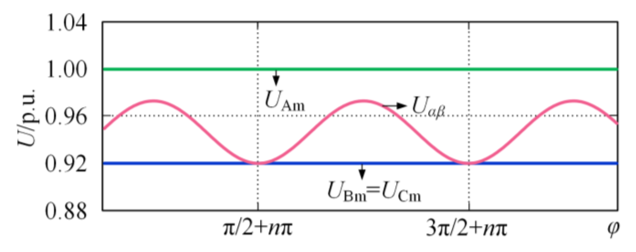
In summary, during interphase faults, Uαβ only accurately reflects the faulted phase voltage drop magnitude at specific phase angles, while it generally underestimates the actual fault severity due to its periodic variation.
Figure 2 illustrates the response of Uαβ based on Equations (9)–(12), where UAm remains constant and UBm as well as UCm drop to 0.92 p.u. The results show that the Uαβ value oscillates between the magnitudes of UAm and UBm/UCm, thus failing to effectively quantify the worst-case scenario in which the commutation voltage UBC drops to 0.92 p.u. Particularly when faults coincide with the peaks of Uαβ, the severity assessment becomes highly distorted, significantly impacting the performance of control systems.
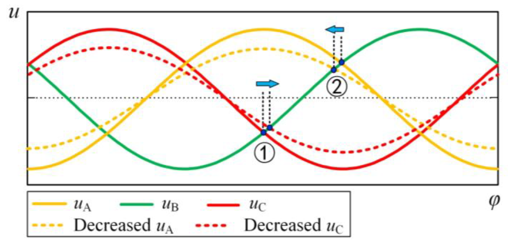
Since interphase faults do not introduce zero-sequence current, the single-phase fault criterion is not activated, and CFPREV can only rely on the three-phase fault criterion for predictive control. However, as analyzed above, the three-phase criterion cannot accurately quantify the commutation voltage drop under interphase faults. Moreover, interphase faults can cause zero-crossing shifts of the commutation voltage. As shown in Figure 3, assuming an AC interphase fault, when commutation voltage zero-crossing point (①) shifts backward, the risk of commutation failure in the corresponding commutation process is reduced; conversely, when zero-crossing point (②) shifts forward, the commutation failure risk in the corresponding process is increased. Therefore, after a zero-crossing shift occurs under interphase faults, the risk variation of commutation failure is uncertain for individual commutation processes. From the perspective of the overall DC system, however, the most severe commutation condition must be considered, leading to an aggravated commutation failure risk and more pronounced limitations of CFPREV. When voltage distortion after faults is taken into account, the analysis method is similar. Although its impact on individual commutation processes remains uncertain, from the system-wide perspective, it will inevitably have adverse effects on certain commutation processes, thereby exacerbating the overall commutation failure risk.

4. Improved Commutation Failure Prevention Control

The existing CFPREV demonstrates two main limitations during interphase faults: inability to independently quantify the magnitude of faulted phase voltage drop and failure to account for commutation voltage zero-crossing shifts caused by interphase faults. To address these issues, we propose real-time per-phase voltage drop calculation and commutation voltage zero-crossing shift prediction algorithms, thereby developing an improved commutation failure prevention control strategy.

4.1. Real-Time Per-Phase Voltage Drop Calculation

Let the calculation period be defined as Ts, with current and previous calculation instants being kTs and (k − 1)Ts respectively. The three-phase voltages at current instant can be expressed as:
u x ( k ) = U x m cos φ x x { A ,   B ,   C }
Here, φx represents the current phase angle. When Ts is sufficiently small, the voltage magnitude at (k − 1)Ts can be considered identical to Uxm:
u x ( k 1 ) = U x m cos φ x 2 π T s f
Further, we define the d-axis and q-axis components of the magnitude Uxm as:
U x d = U x m cos φ x
U x q = U x m sin φ x
Note that φx contains the time-varying term ωt, making Uxm difficult to solve directly. However, by combining Equations (14)–(17) establishes relationships between Uxm and ux (k), ux (k − 1):
U x d = u x ( k )
U x q = u x k 1 u x k cos 2 π T s f sin 2 π T s f
U x m = U x m 2 cos 2 φ x + U x m 2 sin 2 φ x = U x d 2 + U x q 2
Using Equations (18)–(20), the per-phase voltage magnitudes can be calculated at corresponding instants by utilizing information from two sampling points.
The calculation period, Ts, should exceed the sampling period to avoid excessive output fluctuations caused by voltage harmonics under normal conditions, while remaining sufficiently short to ensure a sensitive response post-fault. Specific values should be determined through practical engineering tests.

4.2. Real-Time Commutation Voltage Zero-Crossing Shift Prediction

Based on the previously provided definitions, the phase angle at any instant can be expressed as:
φ x = tg 1 U x q / U x d U x q 0 , U x d 0 tg 1 U x q / U x d + π U x q 0 , U x d < 0 tg 1 U x q / U x d + π U x q < 0 , U x d < 0 tg 1 U x q / U x d + 2 π U x q < 0 , U x d 0
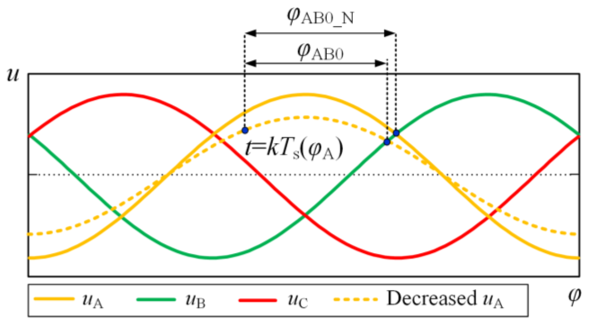
As illustrated in Figure 4, taking the natural commutation point advance of the 2B-phase (i.e., the zero-crossing advance of the AB-phase line voltage) as an example:
At the current instant (t = kTs), given the A-phase voltage phase angle φA and magnitude UAm, the phase difference between the current instant and the next line voltage zero-crossing, φAB0_N, varies within in the range of [0, π]:
φ AB 0 _ N = mod π 3 φ A ,   π
Assuming that the A-phase voltage experiences drops during faults, the phase difference between the current instant and the next natural commutation point can be expressed as:
φ AB 0 = mod t g 1 U a d U b d U a q U b q ,   π
The zero-crossing shift ΔφAB0, varies within the range of (−π/2, π/2):
Δ φ A B 0 = φ A B 0 _ N φ A B 0 π φ A B 0 _ N φ A B 0 π 2 φ A B 0 _ N φ A B 0 + π φ A B 0 _ N φ A B 0 π 2 φ A B 0 _ N φ A B 0 elsewhere

4.3. Improved Commutation Failure Prevention Control for Interphase Short-Circuit Faults

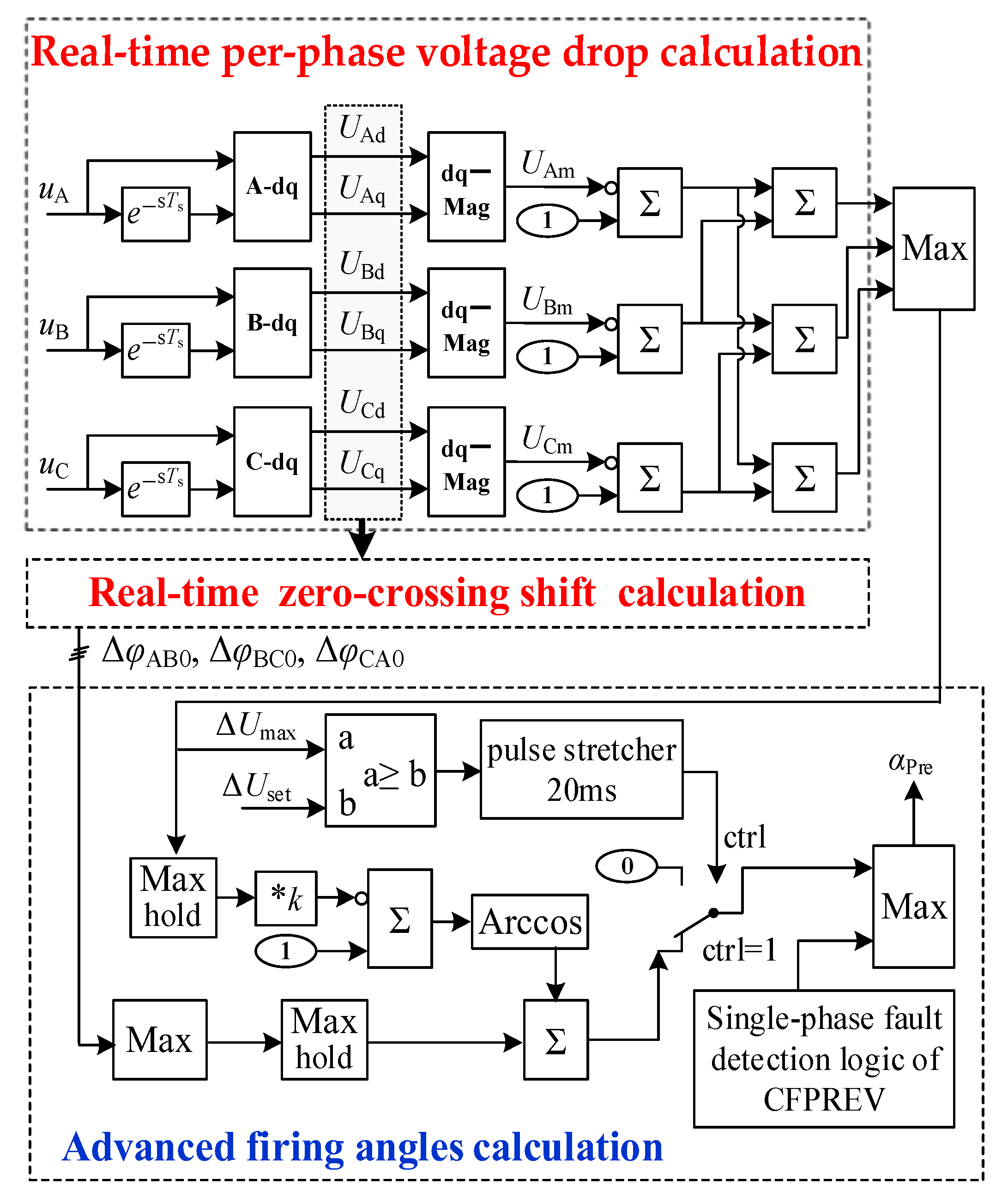
Based on the proposed real-time algorithms for calculating per-phase voltage drop and zero-crossing shifts, we have designed an improved commutation failure prevention control strategy that effectively addresses interphase short-circuit faults. The control block diagram of the proposed strategy is shown in Figure 5. Based on the instantaneous values of the three-phase inverter-side AC bus voltages and their stored values 5 ms earlier (implemented by the e−sTs component in the figure), the real-time voltage drop of each phase is calculated. To account for the most severe commutation voltage drop, the maximum drop among the three phases, ΔUmax, is selected and fed into the advance firing control module. On the one hand, ΔUmax is compared with the preset threshold ΔUset to generate the enabling signal for the advance firing control module; on the other hand, its maximum value within 12 ms (realized by the max hold component in the figure) is used to calculate the advance firing angle. It should be noted that, once activated, the advance firing control module is deliberately held for at least 20 ms (through the 20 ms extension component in the figure) to avoid frequent switching on and off. In this work, ΔUset is set to 0.1, while in engineering practice it can be further adjusted and optimized according to actual conditions. The improved strategy primarily enhances the detection speed of interphase faults while maintaining the capability of detecting three-phase faults, ultimately coordinating with the conventional single-phase fault detection logic to determine the optimal advanced firing angles.

5. Case Study

5.1. Verification of Per-Phase Calculation

The proposed real-time per-phase calculation algorithms for voltage drop magnitude and commutation voltage zero-crossing shift are initially validated using actual field-measured voltage data from a 2023 commutation failure event caused by an interphase short-circuit fault near a domestic DC inverter station.
Figure 6 presents the recorded AC bus voltage waveforms during the commutation failure event. Following the fault, phases A and B exhibit significant voltage amplitude reduction while phase C maintains amplitude but exhibits notable waveform distortion. The analysis presented in [32] indicates that the conventional CFPREV control failed to detect this interphase fault promptly due to insufficient sensitivity, activating only after the commutation failure had occurred.
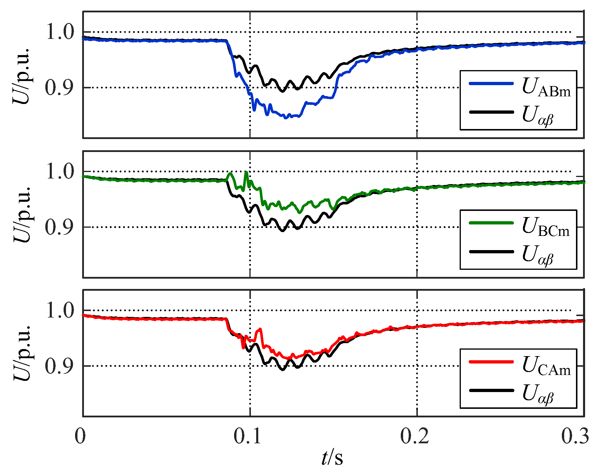
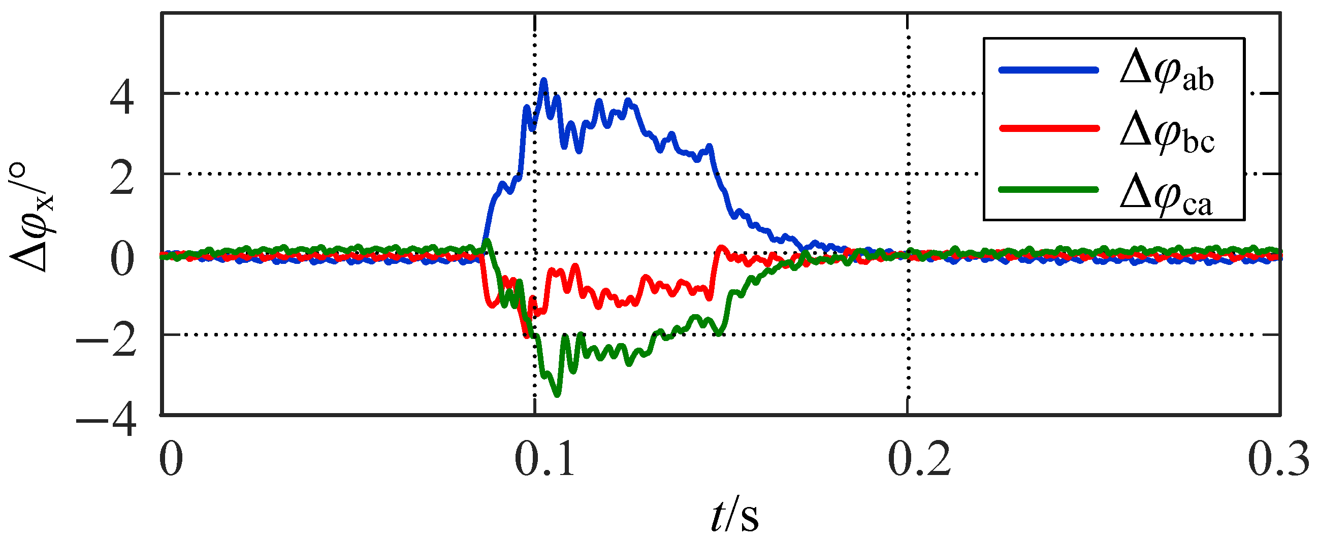
The proposed algorithms calculate real-time voltage drop magnitudes and zero-crossing advances for the line voltages UAB, UBC and UCA, with the results shown in Figure 7 and Figure 8. Figure 7 compares the composite three-phase voltage index Uαβ from the conventional CFPREV method with the individual line voltage magnitudes UABm, UBCm and UCAm. During the AB interphase fault, UABm exhibits a faster and more significant decline than UBCm and UCAm, accurately reflecting the actual fault condition. In contrast, the magnitude reduction of Uαβ falls between those of UABm and UBCm/UCAm, thereby failing to capture the worst-case scenario. Figure 8 shows that the commutation voltage zero-crossing for UAB advances immediately after the fault by approximately 4°, consistent with the measured results shown in Figure 6. In contrast, UBC and UCA exhibit delayed zero-crossings behavior. These results demonstrate that the proposed algorithms successfully quantify faulted-phase voltage drops and predict the corresponding zero-crossing shifts in real-time.

5.2. Simulation Analysis of Commutation Failure Mitigation

The CIGRE HVDC benchmark test model in the PSCAD/EMTDC simulation platform is selected as the reference system, upon which both the conventional CFPREV control strategy and the proposed improved strategy are implemented. An inductive fault is applied at the inverter-side AC bus, where a smaller fault inductance corresponds to a shorter electrical distance between the fault point in the equivalent inverter-side AC system and the converter bus, resulting in a more severe commutation voltage sag and a higher likelihood of commutation failure. By comparing the responses of the two strategies under different fault inductances, their respective capabilities in suppressing commutation failure are evaluated.
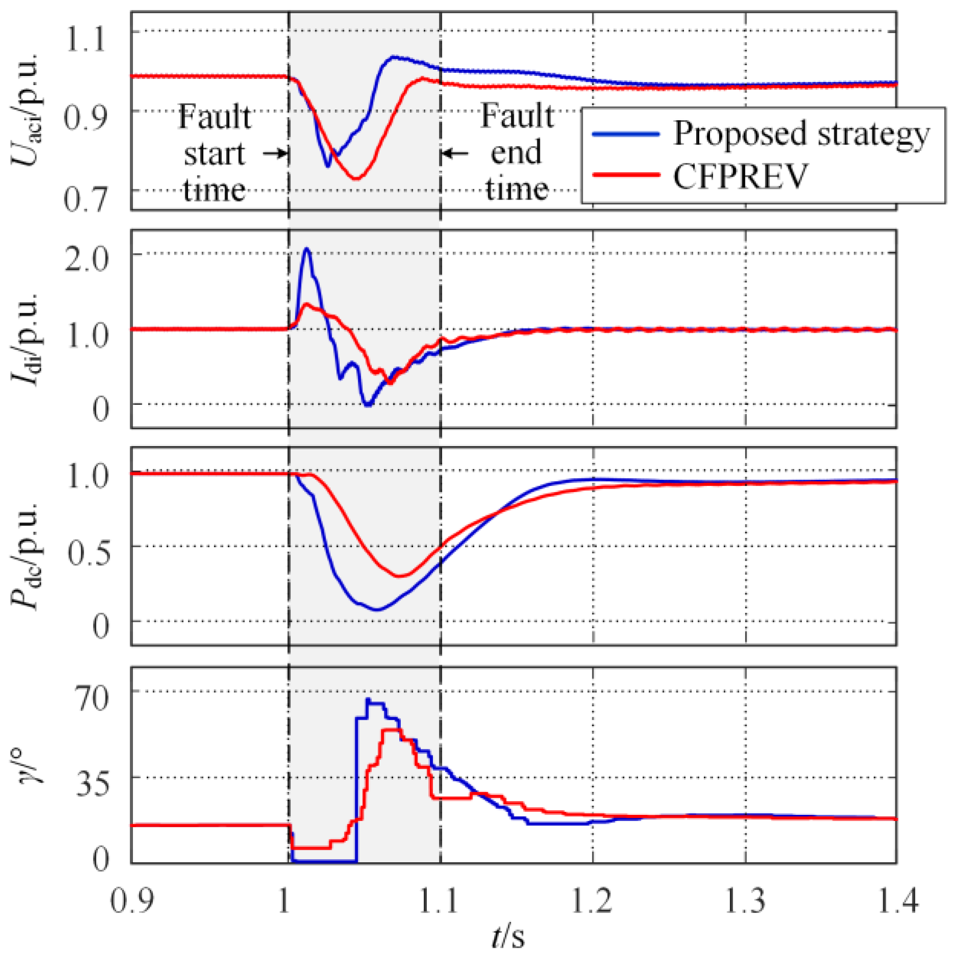
An interphase short-circuit fault, modeled with a 1.20 H inductance, is applied at the inverter-side AC bus from 1.000 s to 0.1 s. Figure 9 compares the key electrical quantities (Uaci, Idi, Pdc, γ) under both control strategies. After the fault, Uaci drops rapidly. Under conventional control, γ decreases to 0°, triggering commutation failure, Idi surges to twice rated value, and Pdc declines sharply. In contrast, the proposed strategy maintains γ above 5.5° through advanced firing, thereby preventing commutation failure and effectively suppressing the Idi surge and Pdc drop.
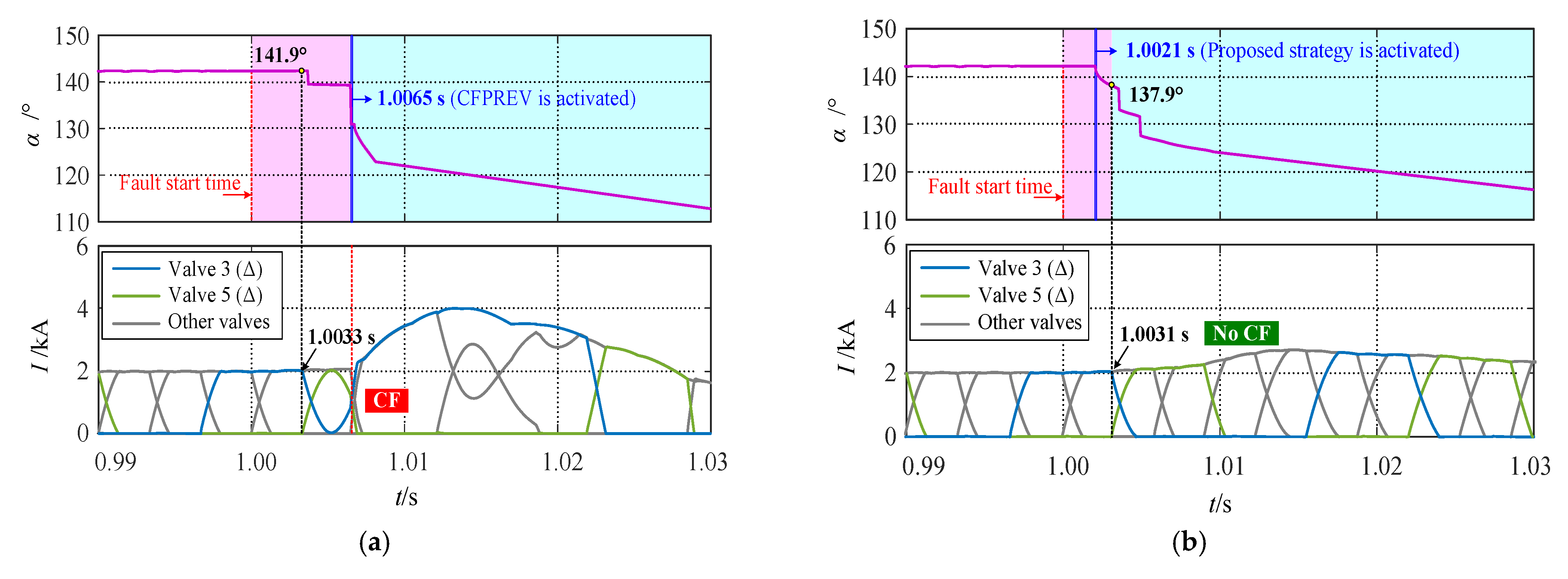
Figure 10 provides detailed comparisons of advanced firing commands and valve current responses. Under conventional CFPREV (Figure 10a), fault detection occurs at 6.5 ms, resulting in an undetected period (highlighted in pink), during which valve 5 fires at 1.0033 s with insufficient commutation margin, leading to unintended re-conduction of valve 3. Although CFPREV is activated at 1.0065 s, it fails to rectify the ongoing commutation failure. In contrast, the proposed strategy (Figure 10b) detects faults within 2.1 ms through real-time per-phase calculations and advances the firing of valve 5 to 1.0031 s, thereby ensuring adequate commutation margin.
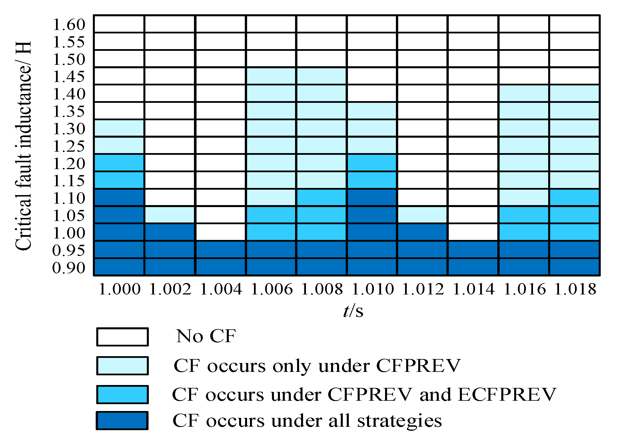
Extensive simulations validate the applicability of the proposed strategy across interphase fault instances (from 1.000 s to 1.018 s in 2 ms steps) and inductances (ranging from 0.90H to 1.60H in 0.05H steps). Under each fault condition, the commutation failure immunity of the system was compared for three control strategies: the proposed strategy, the conventional CFPREV strategy, and the enhanced CFPREV (ECFPREV) strategy reported in reference [33]. The results are shown in Figure 11.
It can be observed that when the fault inductance lies in the range of 1.25–1.45 H, both the proposed strategy and ECFPREV can suppress commutation failure, whereas the probability of commutation failure under the conventional CFPREV strategy ranges between 20% and 60%. For fault inductance in the range of 1.15–1.20 H, the proposed strategy remains effective, but ECFPREV shows a 20% probability of commutation failure. When the fault inductance is reduced further to 1.0–1.1 H, commutation failure cannot be completely avoided; however, the probability under the proposed strategy is limited to 20–40%, which is significantly lower than the 40–80% observed under ECFPREV. Overall, the results demonstrate that the proposed strategy provides a consistent improvement in commutation failure immunity of HVDC systems under interphase faults.
It should also be noted that the advantage of the proposed strategy exhibits a dependence on the fault initiation time. This is primarily because the commutation process is discrete in time: when the initiation instant of commutation falls within the time window corresponding to the response difference between the proposed and conventional strategies, the superiority of the proposed approach becomes most evident.
In the above simulation analysis, the short-circuit ratio (SCR) was set to 2.5. To further verify the applicability of the proposed strategy under different SCR conditions, additional simulations were carried out with SCR values of 2.0 and 3.0. The critical fault inductance Lc—defined as the maximum fault inductance that can still trigger commutation failure—was compared between the conventional CFPREV and the proposed improved CFPREV. The fault initiation time was set to 1.006 ms in all cases. The simulation results are presented in Table 1. It can be observed that, under different SCR conditions, the critical fault inductance of the improved CFPREV is consistently smaller than that of the conventional CFPREV, indicating that the proposed method can withstand more severe AC faults and achieve superior commutation failure suppression performance.

6. Discussion

The improved commutation failure prevention control strategy for interphase short-circuit faults leads to the following conclusions based on theoretical analysis and extensive simulations:
  • Under interphase faults, the three-phase criterion of the conventional CFPREV method accurately reflects faulted-phase voltage drops only at specific phase angles, generally underestimating fault severity due to periodic variation;
  • Real-time per-phase voltage drop calculation and zero-crossing shift prediction can be achieved using two adjacent voltage samples;
  • Case studies and simulations demonstrate the strategy effectively enhances system immunity against commutation failures induced by interphase faults;
  • The proposed strategy is essentially built upon the conventional CFPREV framework by incorporating phase-by-phase voltage calculation and phase-specific prediction of commutation voltage zero-crossing shifts. Therefore, no additional primary equipment is required, and the algorithm can be directly implemented within the HVDC control and protection devices, relying on existing hardware units and computational resources to optimize the control functionality. The proposed algorithm involves no complex calculations or iterative processes, making it straightforward to implement, and it shows good potential for integration with existing control and protection functions.
In future work, researchers will investigate the limitations of the proposed strategy under more complex operating conditions, such as clarifying its effectiveness under harmonic distortion, voltage asymmetry, non-fault disturbances, and different arc models, as well as assessing potential adverse impacts arising from interactions with other HVDC control functions (e.g., low-voltage current limiting). In addition, more comprehensive simulation validations will be performed, including statistical analyses of detection time distribution and extinction angle margin distribution, together with implementation and verification on the RTDS platform, in order to further refine the strategy and enhance its application potential in practical engineering.

Author Contributions

Conceptualization, L.L. and X.L.; methodology, Y.T.; validation, L.L.; formal analysis, X.L.; investigation, Y.T.; writing-original draft preparation, L.L.; writing-review and editing, Y.L. and K.C. All authors have read and agreed to the published version of the manuscript.

Funding

This research was funded by State Grid Sichuan Electric Power Company Science and Technology Project under grant 521997250017.

Data Availability Statement

Data is unavailable due to privacy.

Conflicts of Interest

The authors declare no conflict of interest.

References

  1. Lü, P. Research on HVDC Operation Characteristics Under Influence of Hybrid AC/DC Power Grids. Power Syst. Technol. 2022, 46, 503–510. [Google Scholar]
  2. Li, D.; Gao, Y.; Sun, M. A General Self-Adaptive DC Current Control of LCC-HVDC for Eliminating Subsequent Commutation Failure. IEEE Trans. Power Deliv. 2023, 38, 2232–2235. [Google Scholar] [CrossRef]
  3. Hong, L.; Zhou, X.; Liu, Y.; Xia, H.; Yin, H.; Chen, Y. Analysis and Improvement of the Multiple Controller Interaction in LCC-HVDC for Mitigating Repetitive Commutation Failure. IEEE Trans. Power Deliv. 2021, 36, 1982–1991. [Google Scholar] [CrossRef]
  4. Dong, X.; Tang, Y.; Bu, G.; Shen, C.; Song, G.; Wang, Z.; Gan, D.; Hou, J.; Wang, B.; Zhao, B.; et al. Confronting Problem and Challenge of Large Scale AC-DC Hybrid Power Grid Operation. Proc. CSEE 2019, 39, 3107–3118. [Google Scholar]
  5. Guo, Y.; Tan, Z.; Li, X.; Wang, Y.; Liu, Z.; Cai, Z. A Hierarchical Identification Method of Commutation Failure Risk Areas in Multi-Infeed LCC-HVDC Systems. IEEE Trans. Power Syst. 2024, 39, 2093–2105. [Google Scholar] [CrossRef]
  6. Zhu, H.; Hao, L.; Huang, F.; Chen, Z.; He, J. Research on the Suppression Strategy of Commutation Failure Caused by AC Fault at the Sending End. IEEE Trans. Power Deliv. 2023, 38, 3900–3911. [Google Scholar] [CrossRef]
  7. Liu, L.; Lin, S.; Liu, J.; Sun, P.; Li, X.; He, Z. Mechanism Analysis of Subsequent Commutation Failures Caused by Improper Interaction of Controllers. Power Syst. Technol. 2019, 43, 3562–3568. [Google Scholar]
  8. Liu, L.; Lin, S.; Liu, J.; Sun, P.; Liao, K.; Li, X.; He, Z. Analysis and Prevention of Subsequent Commutation Failures Caused by Improper Inverter Control Interactions in HVDC Systems. IEEE Trans. Power Deliv. 2020, 35, 2841–2852. [Google Scholar] [CrossRef]
  9. Zhu, R.; Zhou, X.; Xia, H.; Hong, L.; Yin, H.; Deng, L. Commutation Failure Mitigation Method Based on Imaginary Commutation Process. J. Mod. Power Syst. Clean Energy 2022, 10, 1413–1422. [Google Scholar] [CrossRef]
  10. Li, Z.; Xue, Y.; Tang, Y.; Chen, N.; Yang, C. Adaptive advancement angle compensation for suppressing commutation failures during rectifier-and inverter-fault recovery. IEEE Trans. Power Deliv. 2023, 38, 4287–4301. [Google Scholar] [CrossRef]
  11. Huang, G.; Tian, X.; Yuan, H.; Dong, X.; Zhou, L.; Wang, Q. Commutation failure predictive control based on fast AC voltage measurement in LCC-HVD. IEEE Access 2023, 11, 53634–53642. [Google Scholar] [CrossRef]
  12. Yao, W.; Liu, C.; Fang, J.; Ai, X.; Wen, J.; Cheng, S.-J. Probabilistic analysis of commutation failure in LCC-HVDC system considering the CFPREV and the initial fault voltage angle. IEEE Trans. Power Deliv. 2019, 35, 715–724. [Google Scholar] [CrossRef]
  13. Liu, J.; Liu, L.; Lin, S. An improved commutation failure prevention method based on waveform similarity detection. Autom. Electr. Power Syst. 2021, 45, 132–139. [Google Scholar]
  14. Zhu, J.; Li, Y.; Duan, X. A Constant Extinction Area Based Control Strategy for Suppressing Commutation Failure in Hybrid Dual-Infeed HVDC System. Power Syst. Technol. 2018, 42, 3735–3743. [Google Scholar]
  15. Wang, J.; Wang, Z.; Xuan, X.; Fu, C.; Huang, M. Extinction Angle Control Based on Predictive Calculation and Its Improvement. Power Syst. Technol. 2018, 42, 3985–3991. [Google Scholar]
  16. Wang, J.; Wen, Z.; Wu, Q.; Zheng, R.; Li, X.; Fu, C. Mitigation Methods of HVDC First Commutation Failure During AC Faults. Proc. CSEE 2021, 41, 7314–7325. [Google Scholar]
  17. Zheng, C.; Tang, Y.; Li, Z. Coordinated control strategy for cascading commutation failure mitigation considering reactive power interaction. IEEE Trans. Power Deliv. 2021, 37, 3225–3234. [Google Scholar] [CrossRef]
  18. Li, X.; Chen, S.; Pang, G.; Lei, X.; Liu, Y.; Wang, J. Optimization of Commutation Failure Prevention and Automatic Recovery for East China Multi-infeed High-voltage Direct Current System. Autom. Electr. Power Syst. 2015, 39, 134–140. [Google Scholar]
  19. Wang, Y.; Hou, Y.; Liu, F.; Cao, L.; Li, W.; Xue, F.; Huang, Z. Optimization Method for Startup Threshold of Commutation Failure Prediction Control Considering Coordinated Recovery of Multi-infeed HVDC Systems. Autom. Electr. Power Syst. 2018, 42, 85–90. [Google Scholar] [CrossRef]
  20. Zheng, C.; Zhou, J.; Li, H.; Wan, L.; Sun, H. Impact of Commutation Failure Prediction Control on Voltage Stability and Its Optimization Measures. Autom. Electr. Power Syst. 2016, 40, 179–183. [Google Scholar]
  21. Wang, Y.; Zhang, X.; Mu, Q.; Chen, X.; Sun, L.; Zhang, X. Parameter Optimization of Commutation Failure Prevention and Control of UHVDC Hierarchical Connection to AC Grid System. High Volt. Eng. 2018, 44, 329–336. [Google Scholar]
  22. Lu, J.; Yuan, X.; Zhang, M.; Hu, J. Supplementary Control for Mitigation of Successive Commutation Failures Considering the Influence of PLL Dynamics in LCC-HVDC Systems. CSEE J. Power Energy Syst. 2022, 8, 872–879. [Google Scholar]
  23. Zhou, H.; Yao, W.; Li, C.; Wen, J. A Predictive Voltage Dependent Current Order Limiter with the Ability to Reduce the Risk of First Commutation Failure of HVDC. High Volt. Eng. 2022, 48, 3179–3189. [Google Scholar]
  24. Sun, Q.; Liu, S.; Ding, C.; Wang, X.; Sun, Y.; Zhou, X. Suppression Strategy of Commutation Failure in DC Transmission System Based on VDCOL Parameter Optimization. Guangdong Electr. Power 2023, 36, 58–66. [Google Scholar]
  25. Akhmatov, V. Harmonic Distortion Prediction Methods for Meshed Transmission Grids. Energies 2023, 16, 3965. [Google Scholar] [CrossRef]
  26. Wang, F.; Liu, T.; Zhou, S.; Li, X.; Qiao, G. Mechanism andquantitative analysis method for HVDC commutation failure resultingfrom harmonics. Proc. CSEE 2015, 35, 4888–4894. [Google Scholar]
  27. Zhang, G.; Jing, L.; Wang, B.; Liu, M.; Dong, X. Study on HVDC consecutive commutation failures mitigation method caused byharmonic. Power Syst. Prot. Control 2020, 48, 33–41. [Google Scholar]
  28. Liu, L.; Lin, S.; Liao, K.; Sun, P.; Deng, Y.; Li, X.; He, Z. Extinction angle predictivecontrol strategy for commutation failure mitigation in HVDC systemsconsidering voltage distortion. IET Gener. Transm. Distrib. 2019, 13, 5171–5179. [Google Scholar] [CrossRef]
  29. Xiao, H.; Li, Y.; Duan, X. Enhanced commutation failure predictive detection method and control strategy in multi-infeed LCC-HVDC systems considering voltage harmonics. IEEE Trans. Power Syst. 2020, 36, 81–96. [Google Scholar] [CrossRef]
  30. Wang, Z.; Wang, J.; Fu, C.; Li, Z.; Huang, M. Individual Phase Control of High Voltage Direct Current Based on Single-phase Locked Loop. Autom. Electr. Power Syst. 2018, 42, 160–165. [Google Scholar]
  31. Gong, Y.; Wang, J.; Wang, Z.; Fu, C. A Novel Phase-locked Loop for HVDC. Power Syst. Technol. 2019, 43, 4097–4104. [Google Scholar]
  32. Liu, L.; Li, L.; Tan, B.; Li, X.; Teng, Y.; Zou, Y. Analysis of Bipolar Commutation Failure of HVDC Caused by An Interphase Fault of Transmission Line. Sichuan Electr. Power Technol. 2024, 47, 57–60. [Google Scholar]
  33. Liu, L.; Li, X.; Teng, Y.; Zhang, C.; Lin, S. An enhanced commutation failure prevention control in LCC based HVDC systems. Int. J. Electr. Power Energy Syst. 2023, 145, 108584. [Google Scholar] [CrossRef]
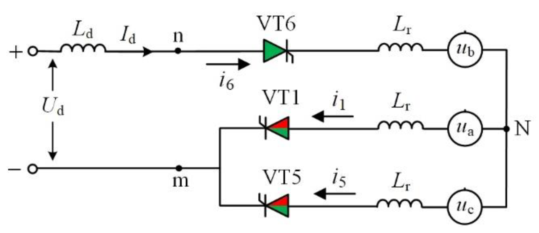
Figure 1. The equivalent circuit during the commutation from valve VT5 to valve VT1.
Applsci 15 09972 g001
Figure 2. Response of Uαβ under phase fault.
Applsci 15 09972 g002
Figure 3. Commutation voltage zero-crossing point shift under an interphase fault.
Applsci 15 09972 g003
Figure 4. Diagram of the advance of commutation voltage zero-crossing point.
Applsci 15 09972 g004
Figure 5. Improved CFPREV control.
Applsci 15 09972 g005
Figure 6. AC bus voltage recording.
Applsci 15 09972 g006
Figure 7. Real-time calculation results of each phase of voltage amplitude drop.
Applsci 15 09972 g007
Figure 8. Real-time calculation results of each phase of voltage zero-crossing point advance.
Applsci 15 09972 g008
Figure 9. Comparison of system response under different control strategies.
Applsci 15 09972 g009
Figure 10. Response of leading firing angle and valve current under different control strategies: (a) Traditional CFPREV strategy; (b) Proposed strategy.
Applsci 15 09972 g010
Figure 11. Comparison of mitigation effect of commutation failure under different fault conditions.
Applsci 15 09972 g011
Table 1. Comparison of commutation failure suppression performance under different SCR conditions.
SCR = 2.0SCR = 2.5SCR = 3.0
Traditional CFPREV strategyLc = 1.7Lc = 1.45Lc = 1.4
Proposed strategyLc = 1.25Lc = 0.95Lc = 0.95
Disclaimer/Publisher’s Note: The statements, opinions and data contained in all publications are solely those of the individual author(s) and contributor(s) and not of MDPI and/or the editor(s). MDPI and/or the editor(s) disclaim responsibility for any injury to people or property resulting from any ideas, methods, instructions or products referred to in the content.