Article

Study on the Multi-Scale Evolution Mechanism of Shear Bands and Cobweb Effect in Solidified Silt Considering Strain Rate

1
School of Civil Engineering, Qingdao University of Technology, Qingdao 266520, China
2
School of Environmental Science and Engineering, Ocean University of China, Qingdao 266520, China
3
School of Civil Engineering, Sun Yat-sen University, Zhuhai 519082, China
4
School of Emergency Management and Safety Engineering, China University of Mining & Technology-Beijing, Beijing 100083, China
5
School of Civil Engineering, Harbin Institute of Technology, Harbin 150006, China
*
Author to whom correspondence should be addressed.
Appl. Sci. 2025, 15(18), 10128; https://doi.org/10.3390/app151810128
Submission received: 7 August 2025 / Revised: 3 September 2025 / Accepted: 15 September 2025 / Published: 17 September 2025

Abstract

The strain rate is a critical element influencing soil strength and the development characteristics of shear bands, which are essential for soil landslides. In order to accurately study the development of shear bands in stabilized silt, digital imaging technology (DIC) combined with triaxial tests was used to study the effects of strain rate on the mechanical properties of stabilized silt and the development mechanism of shear band. Experimental results indicate the following: (1) A strength prediction model incorporating curing agent dosage and curing age was developed, effectively characterizing the strength development law of solidified silt. The optimal dosage of the curing agent was determined to be 8% based on the UCS results. There is an obvious hysteresis effect of peak strain at high strain rate. (2) The degree of strain softening is sensitive to the change in strain rate and curing agent content, and it is positively correlated with strain rate and curing agent content. (3) The “cobweb effect” of the stabilized silt shear band at low strain rate is proposed, which can accurately explain the development law of the stabilized silt shear band. (4) Compared with the maximum strain of 0.04 mm/min, the maximum strain on the shear band decreased by 16.1% and 61.8%, respectively, at 0.4 mm/min and 4 mm/min, and the thickness of the shear band was inversely proportional to the maximum strain on the shear band.

1. Introduction

Extensive silt deposits in the Yellow River Delta region of China are characterized by poor particle grading [1], low cohesive force [2], diminished intensity [3], high porosity, and a significant potential for liquefaction [4]. The inherent geotechnical deficiencies present considerable challenges to engineering construction, while concurrently giving rise to environmental issues such as soil erosion and vegetation degradation [5]. Therefore, systematic laboratory testing and field investigations are essential to characterize the mechanical behavior of silt and optimize its load-bearing performance [6]. Soil solidification is a conventional technique for strengthening the mechanical properties of silt. In view of current research and engineering practices, the predominant soil stabilization agents in geotechnical applications primarily consist of cement [7,8,9] and lime-based inorganic additive [10,11,12,13,14]. These improved materials possess inherent limitations and fail to adequately meet the demands of modern geotechnical engineering development. Wang [15] revealed that adding lime to clay leads to delayed strength development during initial curing phases. As modern industrial activities continue to produce significant quantities of byproducts, researchers have increasingly explored making use of industrial waste—for example, flay ash, chemical gypsum—as composite backfill in engineering applications [16]. Nevertheless, the large-scale application of such industrial by-products could potentially compromise the geomechanically stability of subgrade soils. However, the application of these industrial wastes provides ideas for ameliorating soil problems [17]. Chen [18,19] experimentally verified that the incorporation of industrial solid wastes (including slag and abrasive grain size blast furnace slag) as cementitious makings could significantly raise the mechanical intensity feature of chemically solidified clay. Shen [20] employed cement, slag, coal ash, and guise as curing agents, combined with fibers to raise the properties of contaminated silt. Mozejko [21] examined the stabilization mechanism of silt enhanced with steel slag, showing that the alkaline environment resulting from the hydration of steel slag can facilitate the occurrence of pozzolanic reactions. However, soil treated with industrial waste often exhibits a problem of low early strength. The extensive utilization of industrial waste processing byproducts could potentially induce subsurface soil contamination through leaching mechanisms. Experimental evidence suggests that the synergistic use of cement and lime, when combined with industrial by-products, can effectively improve soil stabilization, where the rapid strength-gain characteristics of cement compensate for the delayed pozzolanic reactions of lime [22]. Consequently, the properties of soil solidified with industrial waste materials have been investigated by numerous researchers. Kang et al. [23] investigated the strength development, pore structure, and classification characteristics of freeze–thaw solidified soil under various confining pressures and water contents through a qualitative and quantitative framework based on a binary medium model. Shang et al. [24] experimentally examined the influence of varying curing ages and confining pressures on the mechanical behavior of solidified soil. Shu et al. [25] investigated the coupling effects of drying–wetting and freeze–thaw cycles on saline soil, utilizing a self-developed apparatus to simulate the combined environmental conditions. Despite the recognized importance of strain rate in controlling strength, its effect on solidified soils has been the subject of relatively limited research.
The emergence, development, and continuity of shear bands are macroscopic manifestations of strain localization in the process of rock and soil mass disasters [26]. The research of shear bands can traceable to Thomas’s [27] seminal work on strain localization theory. With the advancement of testing technologies in recent years, numerous experimental methodologies have been employed to investigate shear bands. Chen [28] and Belmokhtar [29] successfully inferred the local deformation of triaxial soil samples by arranging displacement sensors on the surface of triaxial specimens to measure axial and radial deformation. However, relying solely on displacement transducers for localized deformation measurements yields insufficient accuracy. Cheng [30] used CT technology to complete the scanning and rebuilding of each segment of samples in triaxial tests, capturing the tendency of strain changes. Nevertheless, CT technology imposes stringent requirements on soil sample preparation and preservation. Salazar [31] offered a tactic of capturing triaxial specimen images through multiple cameras at various angles. Despite this measure facilitating deformation monitoring, it increases the operational complexity of the imaging system, highlighting the need for further technical optimization. Utilizing DIC, Xu [32] and Wang et al. [33] quantitatively analyzed the spatial strain evolution on soil specimen surfaces during triaxial shear. This approach significantly enhanced the precision in characterizing localized deformation patterns, particularly shear band development. Batiste [34] conducted a study on the distribution of local porosity within the sample and the evolution patterns of shear bands, utilizing CT technology. Among the above test methods, the most effective test method for studying the shear band is DIC [35]. The formation and evolution of shear bands in soils have attracted significant attention, as they may lead to slope failure through landsliding. Li [36] investigated and discussed the development characteristics of residual soil shear zone under different confining pressures based on DVC technology. Liu [37] employed the DIC technique to investigate highly sensitive clay, revealing that specimens under higher confining pressures are more prone to the shape of localized shear bands. Based on the Discrete Element Method (DEM), Su et al. [38] investigated the coupling effects of particle surface roughness and asphericity on the development of shear zones at soil–structure interfaces. Ye et al. [39] performed direct shear tests incorporating particle image velocimetry (PIV) technology to comprehensively investigate the influence of surface roughness and sand properties on shear band behavior. The effects of strain rate on the formation and propagation of shear bands have not been extensively studied.
The progression of slope instability failure and the formation of shear bands demonstrate analogous developmental characteristics, both of which are significantly influenced by strain rate. Nevertheless, the specific effects of strain rate on the evolution of these processes have not yet been fully elucidated. Accordingly, a novel multi-source composite curing agent is employed to stabilize the silt of the Yellow River Delta. Based on DIC-triaxial tests, the mechanical properties of the stabilized silt and the development mechanisms of shear bands were investigated with respect to four key aspects: failure mode, failure path, shear band propagation characteristics, and shear band thickness. The results provide a theoretical basis for improved prediction of slope instability failures.

2. Test Materials and Procedures

2.1. Materials

The tested material, obtained from depositional environments in the Yellow River Delta, exhibits the particle size characteristics illustrated in Figure 1. Following the procedures outlined in the Standard for Geotechnical Testing Methods (GB/T 50123-2019) [40], we conducted comprehensive testing to characterize the fundamental physical parameters of the silt, as summarized in Table 1.
The new multi-source curing agent used in this institute is a mineral-based cementitious material developed by Qingdao Pan Yao New Material Engineering Research Institute, which is a gray powdered inorganic cementitious material. The material is made of a variety of natural inorganic mineral raw materials after physical and chemical activity excitation. It is a new, efficient, green, and environmentally friendly curing material, which is mainly composed of fly ash, mineral powder, lime, and cement. This material exhibits high early-age strength and favorable setting characteristics.
The material mainly stimulates the activity of soil particles, so that soil particles and mineral-based cementitious materials form new cementitious materials to self-solidify, and the materials undergo hydration reactions when exposed to water to generate hydroxides and free calcium ions to form C-S-H gels, cementing soil particles into a whole and improving soil strength. The experimental protocol specifies the dosage of curing agent as the proportional mass of the agent relative to combined mass of the agent and silt, quantified mathematically in Equation (1).
G c = m e m s + m w + m e
where m s is the quality of the sample, g; m w is the quality of water in the sample, g; m e is the quality of curing agent, g.

2.2. Test Procedure

UCS tests are used for stabilized silt in line with ASTM D2166 [41], with binder dosage groups set at 0%, 2%, 4%, 6%, 8%, and 10%. Based on preliminary tests, the specimens were prepared as cylindrical samples with a water content of 18%, dimensions of Ø 39.1 mm × 80 mm (diameter × height), and subsequently cured under controlled conditions of 27 ± 3 °C with relative humidity maintained at 50–55%. To ensure statistical reliability, three specimens were prepared for each dosage of curing agent, with the mean value of the test results being used for analysis. Sample preparation procedures are shown in Figure 2.
In this test, the confining pressure was set to 700 kPa, and the soil sample was consolidated under the action of confining pressure, so the consolidated undrained (CU) triaxial shear test was carried out on the stabilized silt to evaluate the mechanical properties of the stabilized silt with the experimental parameters systematically presented in Table 2. The consolidated silt specimens containing varying concentrations of curing agent were tested under three distinct strain rates (0.04 mm/min, 0.4 mm/min, and 4 mm/min) in accordance with the specifications outlined in the Standard for Geotechnical Testing Methods (GB/T 50123-2019) [40].
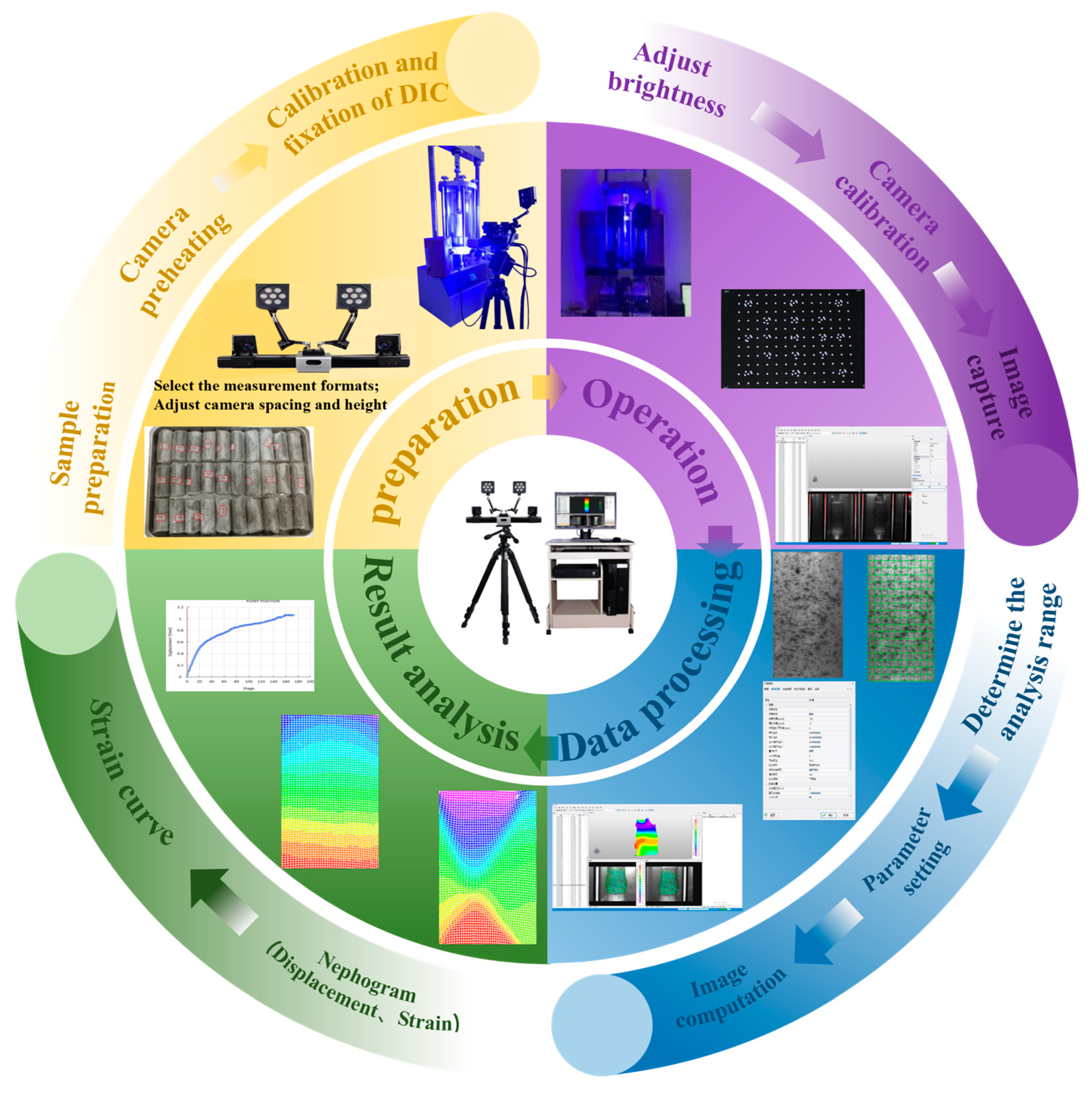
Utilizing a binocular high-resolution imaging setup, the XTDIC 9.5 three-dimensional deformation analysis system acquires synchronized speckle pattern data across successive shear phases of the specimen. Utilizing DIC algorithms, it achieves precise matching of surface deformation points on specimens. Based on parallax data from these points, the system reconstructs three-dimensional coordinates of computational points on the samples surface. The specimen’s displacement field is determined through comparative analysis of 3D coordinate changes across all monitoring points under different deformation states, enabling subsequent strain field computation via numerical differentiation. The analysis utilizing DIC comprises four critical steps: specimen preparation; image acquisition; image data processing; and result analysis. The specific workflow is illustrated in Figure 3.
The triaxial shear test adopts a displacement-controlled loading method, conducting tests at different loading rates of 0.04 mm/min, 0.4 mm/min, and 4 mm/min, respectively. The test is terminated when the axial strain reaches 20%. After the test, the XTDIC analysis system was employed to process the captured images, obtaining the strain fields of stabilized silt under different strain rates. The spatial pattern and evolution of shape in stabilized silt at varying strain rates were analyzed to characterize the shear band features.

3. Results and Discussion

3.1. UCS of Stabilized Silt

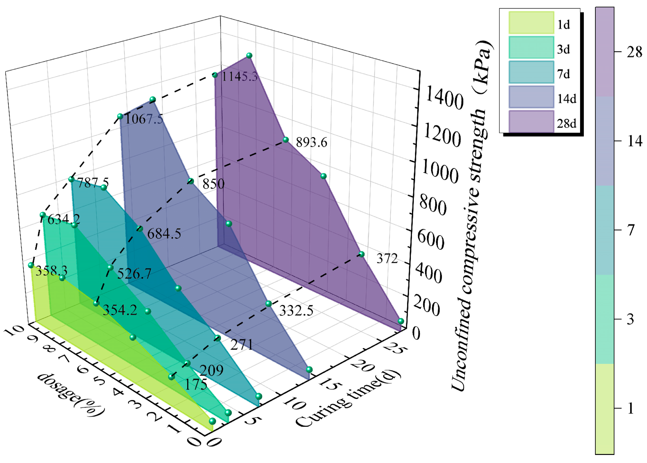
UCS serves as a critical mechanical index for evaluating the mechanical properties of stabilized silt. Figure 4 presents the UCS of stabilized silt under varying dosages of curing agent and curing periods. Experimental results demonstrate a non-monotonic relationship between curing agent content and the mechanical behavior of stabilized silt, characterized by strength enhancement at lower dosages followed by reduction at higher concentrations. Under optimal conditions (2% additive content and 14-day curing duration), the treated silt achieves a peak unconfined compressive strength of 332.5 kPa. With an increased dosage of curing agent of 8% and the same 14-day curing period, the strength of the stabilized silt can achieve 1242.5 kPa, which represents a 3.73-fold increase compared to the strength at 2% dosage of the curing agent under identical curing conditions. Experimental results indicate that when a 10% curing agent dosage is applied, the 14-day cured stabilized silt exhibits an unconfined compressive strength of 1067.5 kPa, which represents a decrease compared to samples containing 8% curing agent under identical curing conditions. Furthermore, experimental observations reveal a time-dependent escalation in unconfined compressive strength, where the most significant strength gain occurs during the initial two weeks of curing [42]. For the stabilized silt with 10% additive content, the UCS after 1-day curing is merely 358.3 kPa, while the 14-day cured specimen reaches 1067.5 kPa. Compared with the non-cured sample at the same additive dosage, this represents a 297.9% strength enhancement. Based on the experimental results, it can be deduced that the mechanical properties of treated silt exhibit significant dependence on both the dosage of curing agent and duration of curing time. The addition of an appropriate amount of curing agent can enhance the strength of the silt.
To accurately predict the strength of stabilized silt under varying curing agent dosages and curing ages, this study developed a strength prediction model accounting for both curing agent dosage and curing age, building upon existing research Equation (2):
S = λ × f ( X ) × f ( T )
where λ is the model parameters, f ( X ) , f ( T ) are a function of the curing agent content and curing age, respectively.
According to Equation (2), the regression analysis of the inclination angles of the shear band under different confining pressures yields:
S = ( 70.4 + 79.8 X 4.1 X 2 ) × ( 1 + 0.25 e 0.15 T )
In the formula, S is the strength of the stabilized silt considering the influence of the curing agent content and the curing age, X is the curing agent dosage, and T is the curing age. Through the prediction model (3) and the test results, it can be concluded that the optimal dosage of curing agent is 8%.
The experimental findings reveal that the application of the curing agent significantly enhances the mechanical properties, particularly the compressive strength, of the stabilized silt. The elevated SiO2 content in the curing agent triggers dual reaction pathways—direct hydration and secondary pozzolanic reactions—when interacting with cement and GGBS components. This synergistic process leads to extensive precipitation of C-S-H gels [43,44]. These hydration products fill the interparticle holes, leading to a more compact granular structure. Furthermore, the release of SiO2 enhances pozzolanic reactivity, fostering robust interfacial bonding among soil particles through the formation of secondary hydration products. This process ultimately consolidates the particulate matrix into a cohesive structural unit. Through a comprehensive experimental investigation involving cyclic triaxial testing coupled with microstructural analysis, Chen [45] systematically examined the dynamic response characteristics of silty clay. The research outcomes demonstrated remarkable consistency with existing literature regarding the soil’s mechanical behavior under cyclic loading conditions. However, excessive addition of the curing agent would result in hydration products failing to effectively bond with soil particles, thereby inhibiting the progression of hydration reactions. These findings can provide substantial support for addressing strength-related issues of silt in future practical engineering projects.

3.2. Stress–Strain Relationship of Stabilized Silt

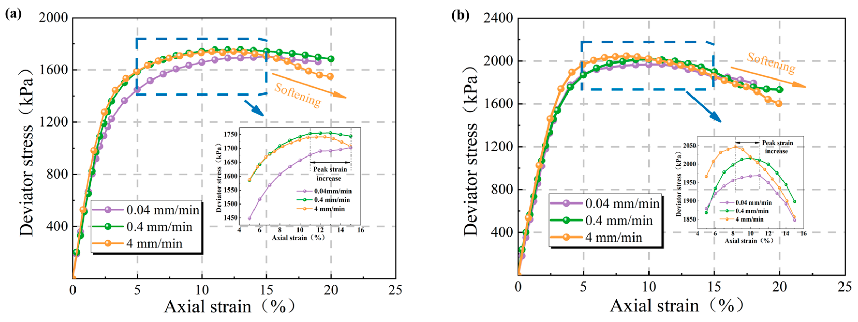
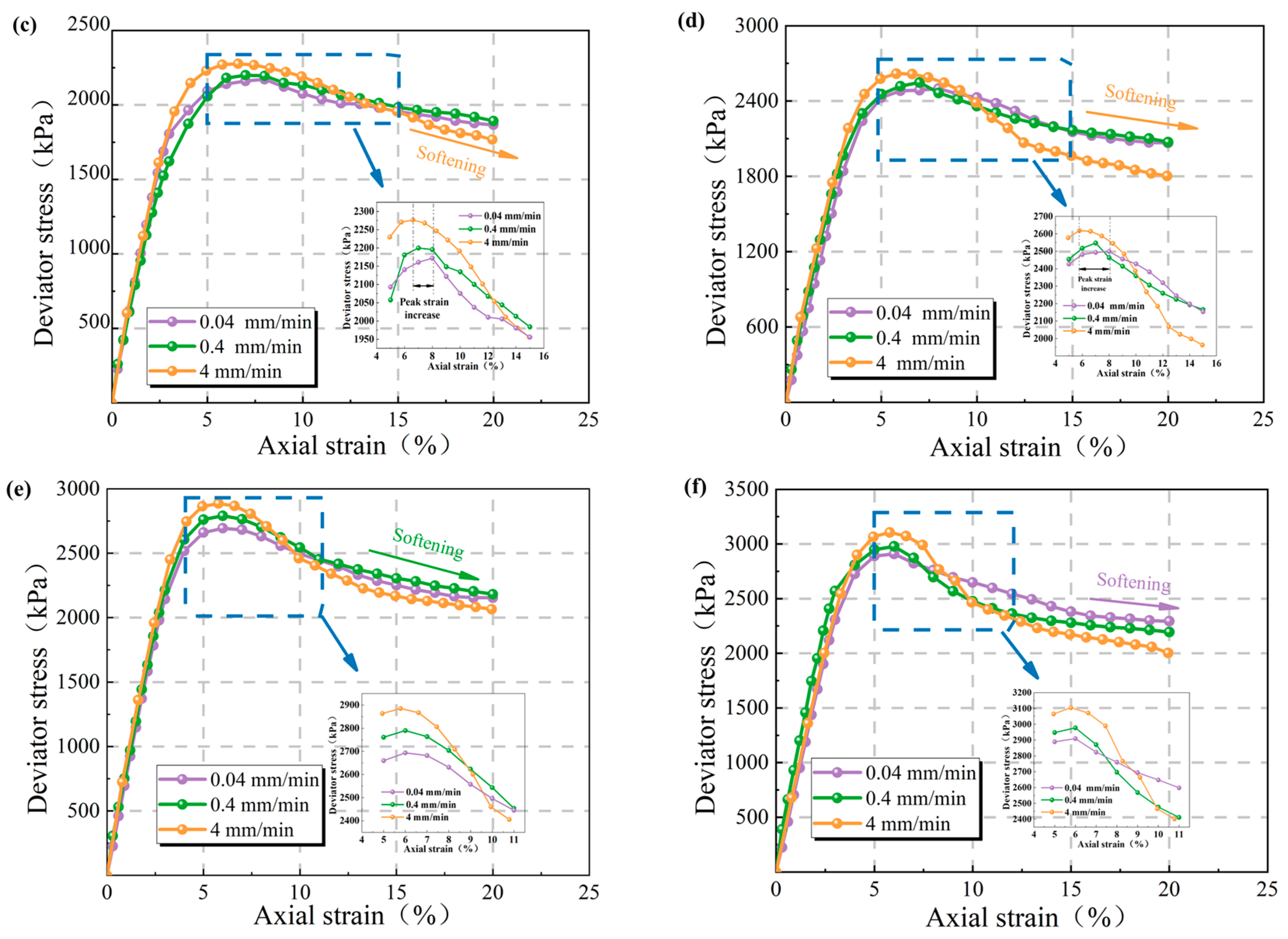
Figure 5 illustrates the stress–strain relationships of stabilized silt under varying strain rates. In the UCS test, the enhancement in compressive strength of specimens with curing ages between 14 and 21 days is relatively gradual. Therefore, specimens cured for 14 days with dosage of curing agent of 0%, 2%, 4%, 6%, 8%, and 10% will be selected for testing, aiming to thoroughly investigate the influence of different strain rates (4 mm/min, 0.4 mm/min, and 0.04 mm/min) on the stress–strain relationship of stabilized silt.
Figure 5 displays that the stress–strain curve of stabilized silt can be generally categorized into four distinct phases: the elastic deformation stage, shear deformation stage, failure stage, and stabilization stage. During the elastic deformation phase, the treated soil exhibits considerable compressibility when subjected to external loading, leading to a notable decrease in void ratio and subsequent microstructural densification, manifesting as pronounced axial strain in the specimen [46].
At an identical dosage, the peak stress increases with the rising strain rate. During undrained testing, excess pore pressure is generated. At elevated strain rates, the transient pore pressure generated in the specimens exhibits limited dissipation capacity, leading to an amplified peak stress response [47]. At elevated strain rates, more particles undergo yield failure, which requires more energy [48], and there is a significant hysteresis effect on the peak strain of the sample; the specimen exhibits strain localization near peak stress. Before reaching the peak stress, higher strain rates result in an augmentation of the maximum stress, accompanied by progressive alterations in the localized strain distribution.
Based on experimental results presented in Figure 5, the peak strength characteristics and strain softening behavior of stabilized silt were quantitatively evaluated under varying dosage of curing agent and strain rates [49]:
s = σ p σ r ε p ε r
S: Strain softening degree, %; σ p : Peak strength, kPa; σ r : Residual strength, kPa; ε p : Strain corresponding to peak strength, %; ε r : σ r corresponding strain, %.
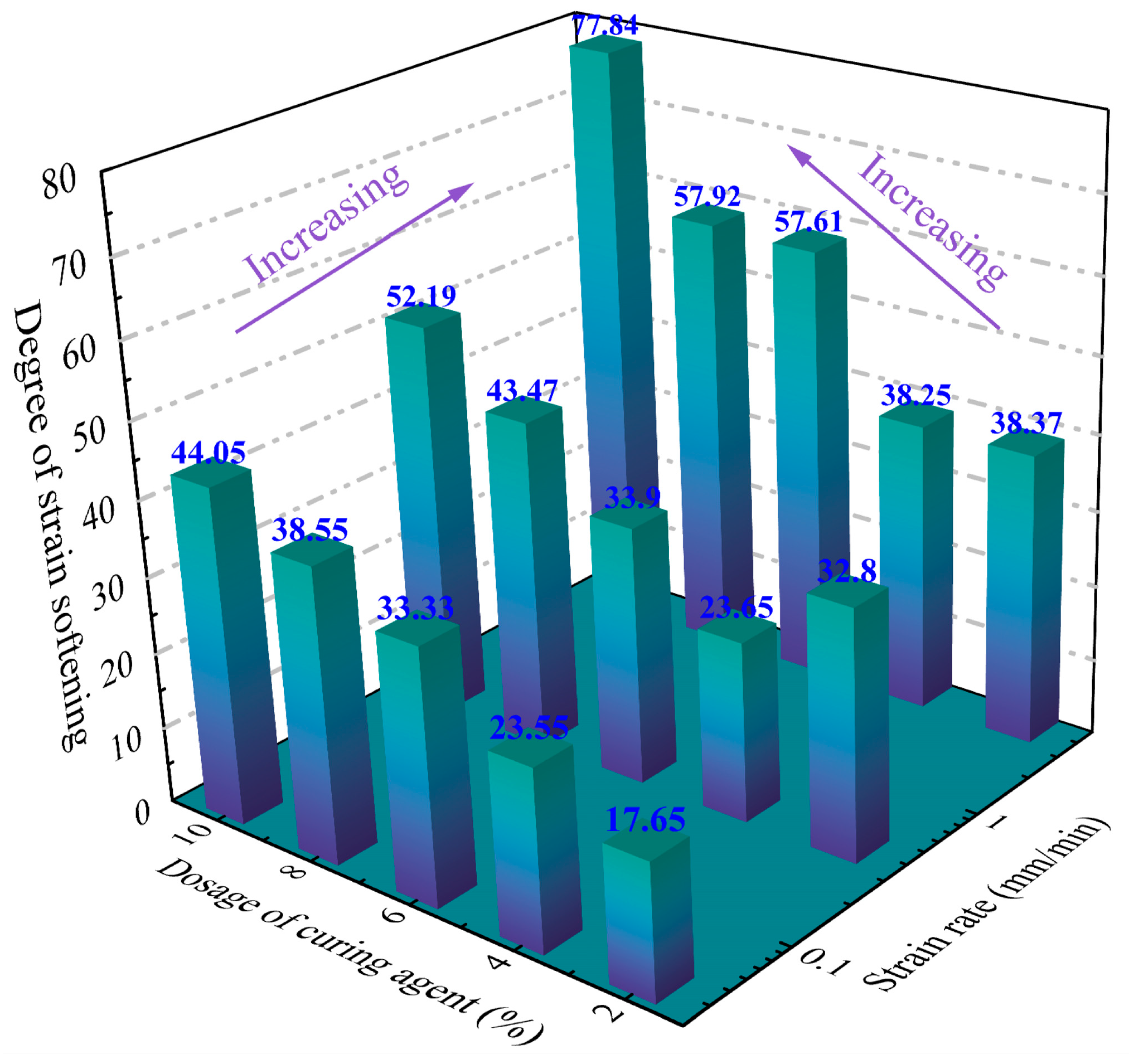
Figure 6 illustrates the influence of curing agent content and strain rate on the degree of strain softening in stabilized silt. As illustrated in the figure, the strain softening degree exhibits sensitivity to variations in strain rate and curing agent content, with a positive correlation observed between strain softening degree and strain rate. Specifically, at a curing agent content of 10%, increasing the strain rate from 0.04 mm/min to 4 mm/min results in a 33.79 kPa increase in strain softening degree. Conversely, at a strain rate of 4 mm/min, elevating the curing agent content from 0% to 10% leads to a 39.47 kPa increase in strain softening degree. These experimental results align well with the previous work of Cai [50], demonstrating a coherent pattern in the observed phenomena.
Under low strain rate conditions, the deformation of the specimen develops uniformly along its length. Such homogeneous deformation prevents the specimen from reaching peak strength through localized instability, while simultaneously avoiding pronounced brittle failure and strain-softening behavior with limited strain range. At elevated strain rates, soil samples demonstrate pronounced heterogeneous deformation patterns, leading to localized stress intensification. The development of localized strain concentrations leads to accelerated stress mobilization in overburdened soil regions, precipitating premature brittle failure. This phenomenon manifests as a distinct post-peak strength degradation, where the heterogeneous strain distribution effectively inhibits the progression of plastic deformation throughout the specimen, consequently diminishing its yield capacity [51]. Meanwhile, under high strain rates, the dissipation time of excess pore water pressure generated by sample compression is relatively short. As a result, the pore pressure in the central region of the shear zone accumulates rapidly and fails to dissipate in a timely manner, and its instantaneous release gives rise to significant strain softening under high strain rate conditions [52].
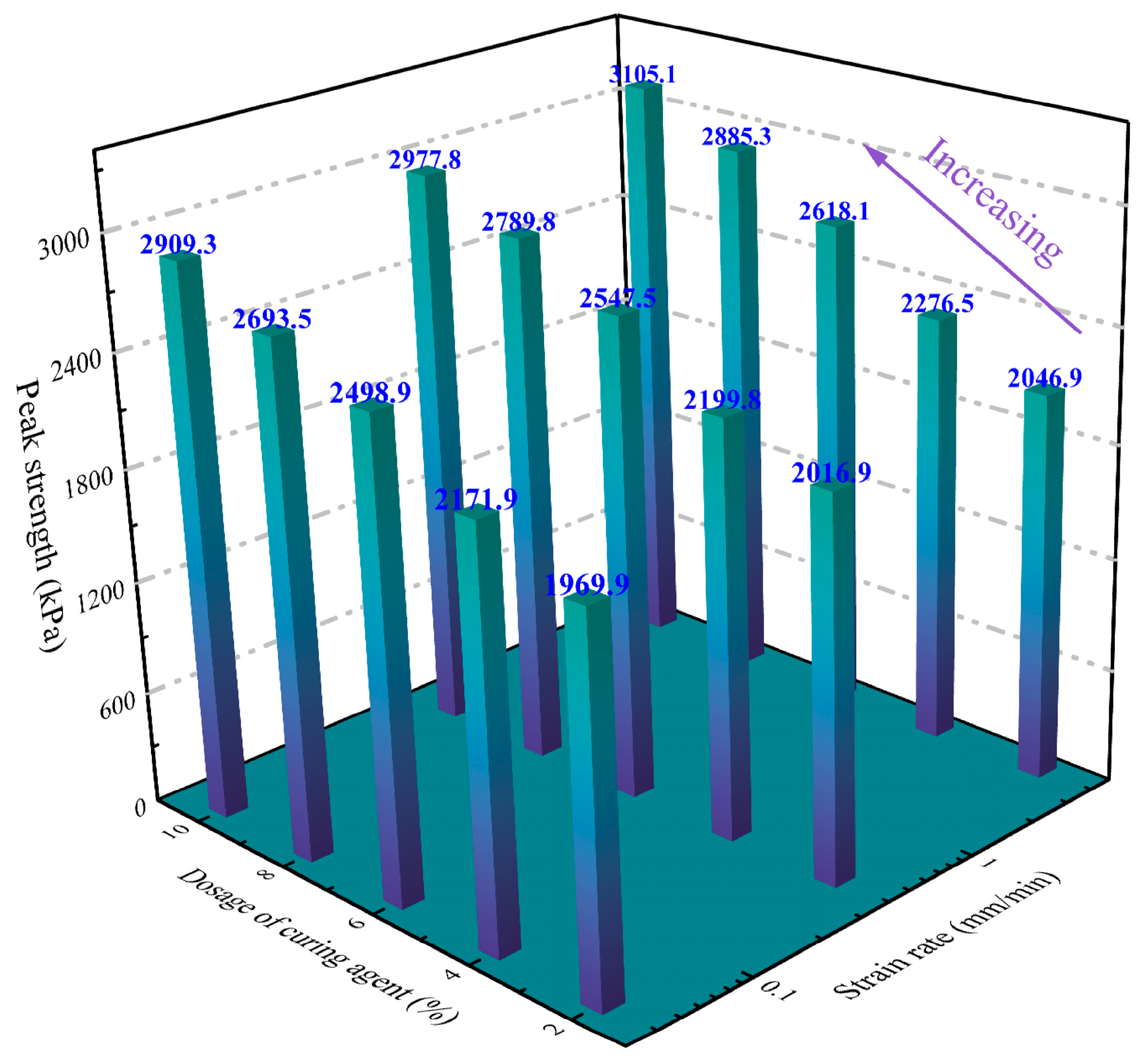
Figure 7 demonstrates the effect of curing agent content and strain rate on the peak strength of stabilized silt. As illustrated in Figure 7, the peak strength of the specimens exhibits significant dependence on both the dosage of curing agent and strain rates. The degree to which strain rate affects undrained shear strength can be quantitatively characterized by analyzing the variation rate of peak strength, as demonstrated by the following formula:
Y = S u S u 0 S u 0 × 100 %
where S u represents the peak strength at a given strain rate, and S u 0 denotes the peak strength at the reference strain rate. A reference strain rate of 0.5% per min was selected for comparative analysis, aligning with the standardized range of 0.5–1.0% per minute as stipulated in the relevant guidelines [40].
Figure 8 shows the relationship between the variation rate of sample peak strength and strain rate under distinct strain rate conditions. The slope of the fitted curve for the peak strength variation rate of stabilized silt shows a positive correlation with the increasing binder content. Elevated concentrations of the stabilizing agent enhance the generation of supplementary cementitious compounds through reactions with the silt [43,44]. These hydration products enhance both the mechanical strength and brittle characteristics of the soil, while simultaneously increasing the strain rate dependence of the specimen’s peak strength.

3.3. Failure Modes and Shear Band Evolution Characteristics of Stabilized Silt

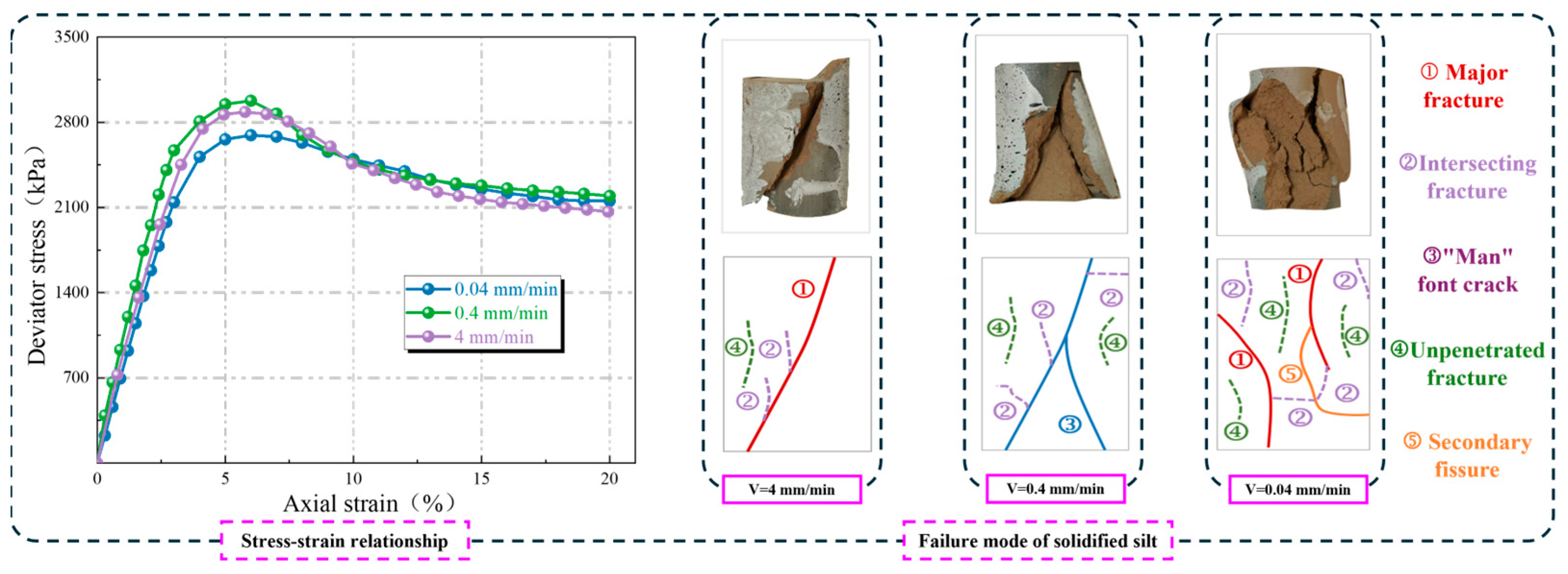
The mechanical response and fracture behavior of stabilized silt specimens subjected to different strain rates are shown in Figure 9, which depicts both the stress–strain curves and associated failure patterns. The experimental findings from unconfined compressive strength tests and stress–strain analyses reveal that the strain rate markedly affects both the failure pattern and the evolution of shear bands in stabilized silt. This research utilizes DIC to monitor real-time displacement fields in stabilized silt specimens, aiming to characterize strain localization patterns under different strain-rate conditions. The research quantitatively characterizes the strain field distribution of stabilized silt corresponding to different strain rates and axial strain levels. The strain field distribution was employed to evaluate specimen failure mechanisms, with particular emphasis on characterizing the evolution patterns of shear bands in stabilized silt across varying strain-rate conditions. The evolution of shear bands can be quantitatively assessed by analyzing the strain field, with particular focus on two key parameters: the peak strain magnitude localized within the shear band and the thickness of the deformation zone.

3.3.1. Failure Mode and Crack Characteristics of Stabilized Silt

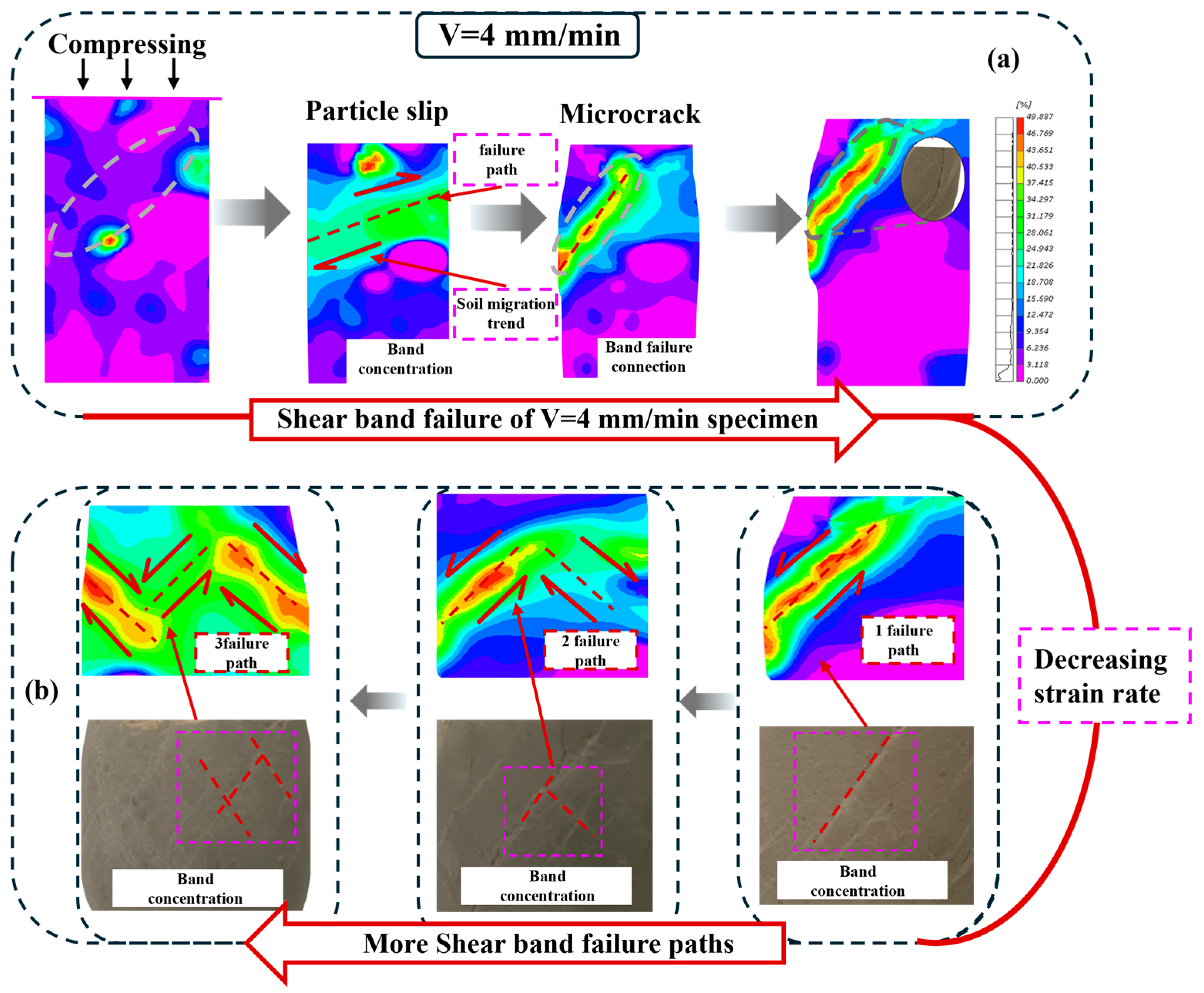
Figure 10a illustrates the development pattern of shear bands in stabilized silt. As shear progresses, soil particles within the specimen form a tightly arranged skeletal structure through interparticle cementation bonds, enabling the assembly to withstand applied loads and associated deformations. Through progressively increasing the applied stress, the bonded soil particles on both sides undergo displacement and rotation in divergent directions, manifesting as bending deformation of interparticle cementation bonds. This ultimately induces cohesive failure within the localized zone, resulting in stress concentration phenomena. With the progressive development of bond degradation, a macroscopic shear band ultimately develops. A relatively single macroscopic cracking path for the stabilized silt specimens at high strain rates is shown in Figure 10b. As strain rate declines, macroscopic fracture trajectory within the specimen evolves into increasingly complex branching patterns, ultimately fragmenting the material into discrete, interconnected segments. The ductile nature of cementation bonds between soil particles allows these curved bonds to progressively deform under low strain rates, thereby effectively redistributing applied stresses. This stress transfer mechanism facilitates a more uniform spatial distribution of external loading, effectively minimizing interparticle debonding risks while alleviating localized stress accumulation effects.
Simultaneously, during the shearing process, microcracks are initiated within the specimen; these microcracks subsequently propagate, concentrate, and coalesce to form a macroscopic shear band. As strain rates diminish, a higher concentration of localized microcracks develops, which subsequently manifests as increased complexity in macroscopic fracture trajectories. Under conditions of diminished strain rates, microcracks exhibit a more diffuse spatial arrangement, which attenuates the dominance of primary shear bands while promoting the nucleation of subsidiary shear bands within the specimen. The observed behavior demonstrates a negative correlation with the applied strain rate [53], leading to pronounced lateral expansion in the specimen.
From a micromechanical perspective, analyzing energy dissipation provides fundamental insights into the failure mechanisms of granulated materials, offering a robust framework to interpret specimen behavior under loading conditions [54,55]. In an independent particle system, the cementation bonds between soil particles absorb and accumulate externally input energy through deformation, subsequently releasing it via bond rupture. At reduced strain rate conditions, the specimens exhibit enhanced capacity for strain energy accumulation, attributable to the more homogeneous spatial distribution of stored energy within the material matrix. Meanwhile, under low strain rates, soil particles within the specimen are afforded more time to undergo rotation, allowing micro-cracks to propagate along the path of least energy consumption. At reduced strain rates, the specimen exhibits a more homogeneous strain energy distribution, which promotes scattered microcrack initiation and facilitates the formation of multiple fracture propagation trajectories. Under low-strain conditions, the structural coherence of the specimen is preserved, necessitating higher energy input to disrupt the cemented interfacial bonds. This process suppresses the generation of microcracks within the specimen and retards energy release.

3.3.2. Development Characteristics of Shear Bands in Stabilized Silt

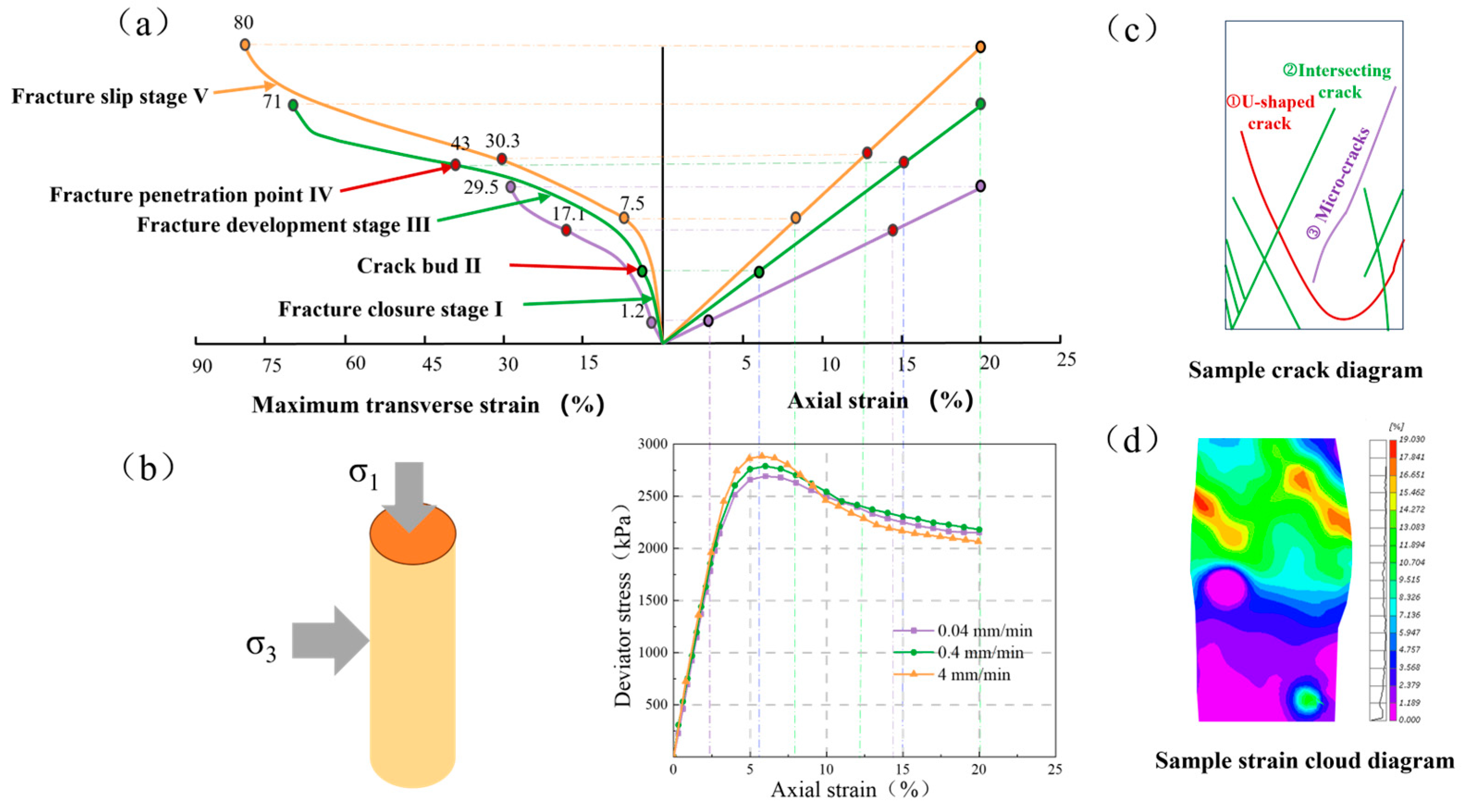
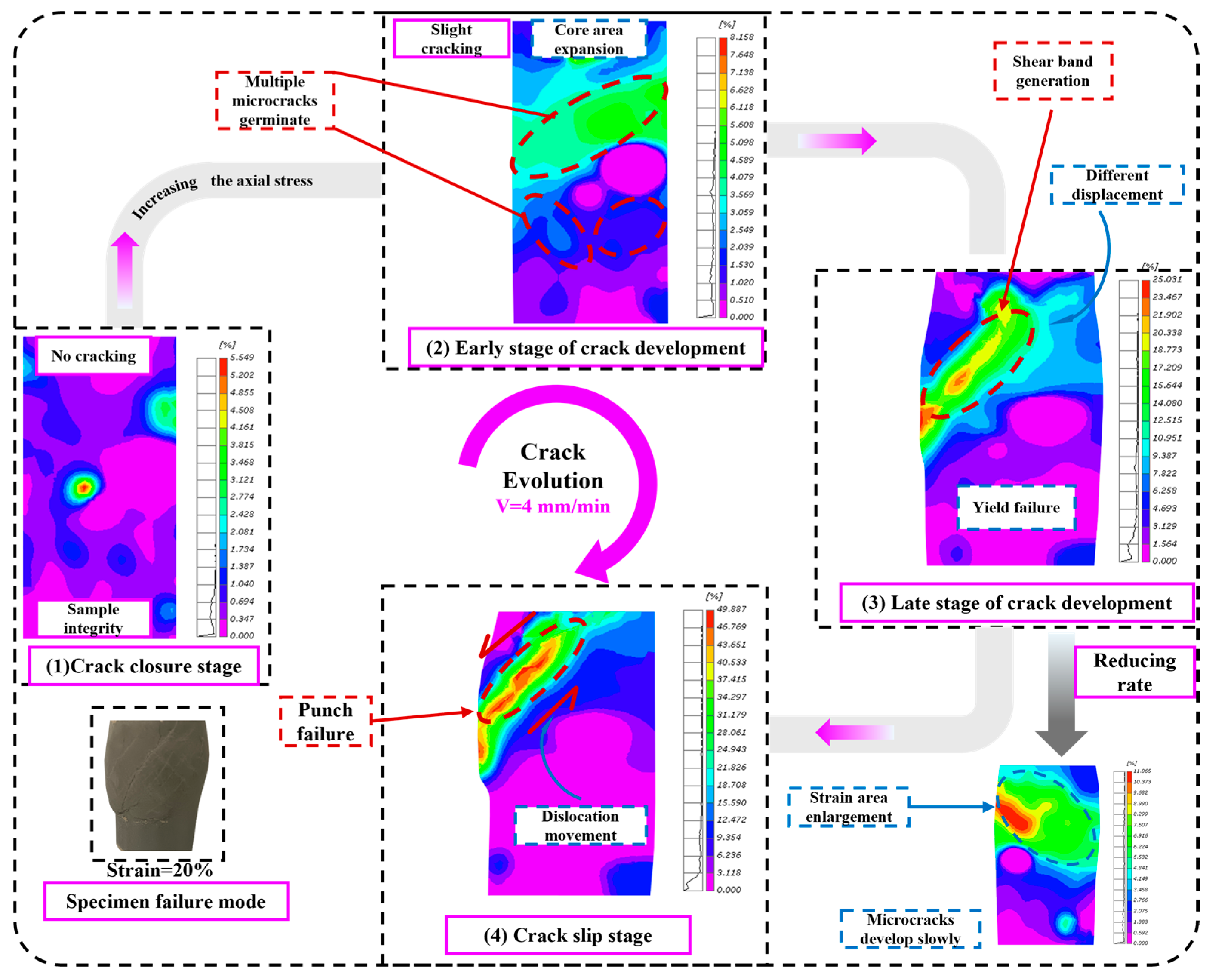
The genesis of shear zones involves multiple phases of structural evolution [56]. Figure 11a demonstrates that the shear band development in stabilized silt can be categorized into three distinct phases based on the incremental patterns of the curve: Crack closure stage, Crack development stage, and Crack sliding stage. The strain variation in soil particles within the specimen reveals the flux mechanism of shear bands. To further investigate the crack propagation process, Figure 12 illustrates the evolution of internal microstructure during fracture development in stabilized silt. Figure 12 demonstrates that during the crack closure phase, the specimen undergoes elastic deformation while effectively maintaining its structural integrity. Interparticle slight movements occur between soil grains, where the cementation bonds accommodate the random minor displacements without inducing micro-cracks. During the plastic deformation phase, microcracks initiate at spatially distributed sites within the specimen and subsequently advance in a progressive manner. As the applied stress progressively rises, the accumulated strain energy among soil particles surpasses the elastic threshold, triggering the rapid initiation and propagation of microcracks. In contrast, low strain rate conditions lead to markedly slower microcrack evolution due to restrained energy dissipation dynamics; With further shearing, the specimen underwent yielding failure, initiating the shape of shear bands.
The development of shear bands is fundamentally driven by localized particle displacement disparities along micro-crack interfaces within the shear band. This kinematic heterogeneity generates opposing motions of adjacent soil particles across the incipient shear plane, ultimately facilitating shear band propagation [57]. In contrast, specimens subjected to lower strain rates exhibit a relatively uniform distribution of strain energy within the material due to the reduced loading rate, resulting in an expansion of the strained zone. In the fracture slip phase, crack propagation exhibits significant deceleration and tends to stabilize. The test specimen exhibits complete perforation failure characterized by the formation of a fully mobilized shear band, resulting in distinct relative movement between the overlying and underlying soil strata. This suggests that specimens with low strain rates may be subjected to more strain, resulting in improved specimen ductility.
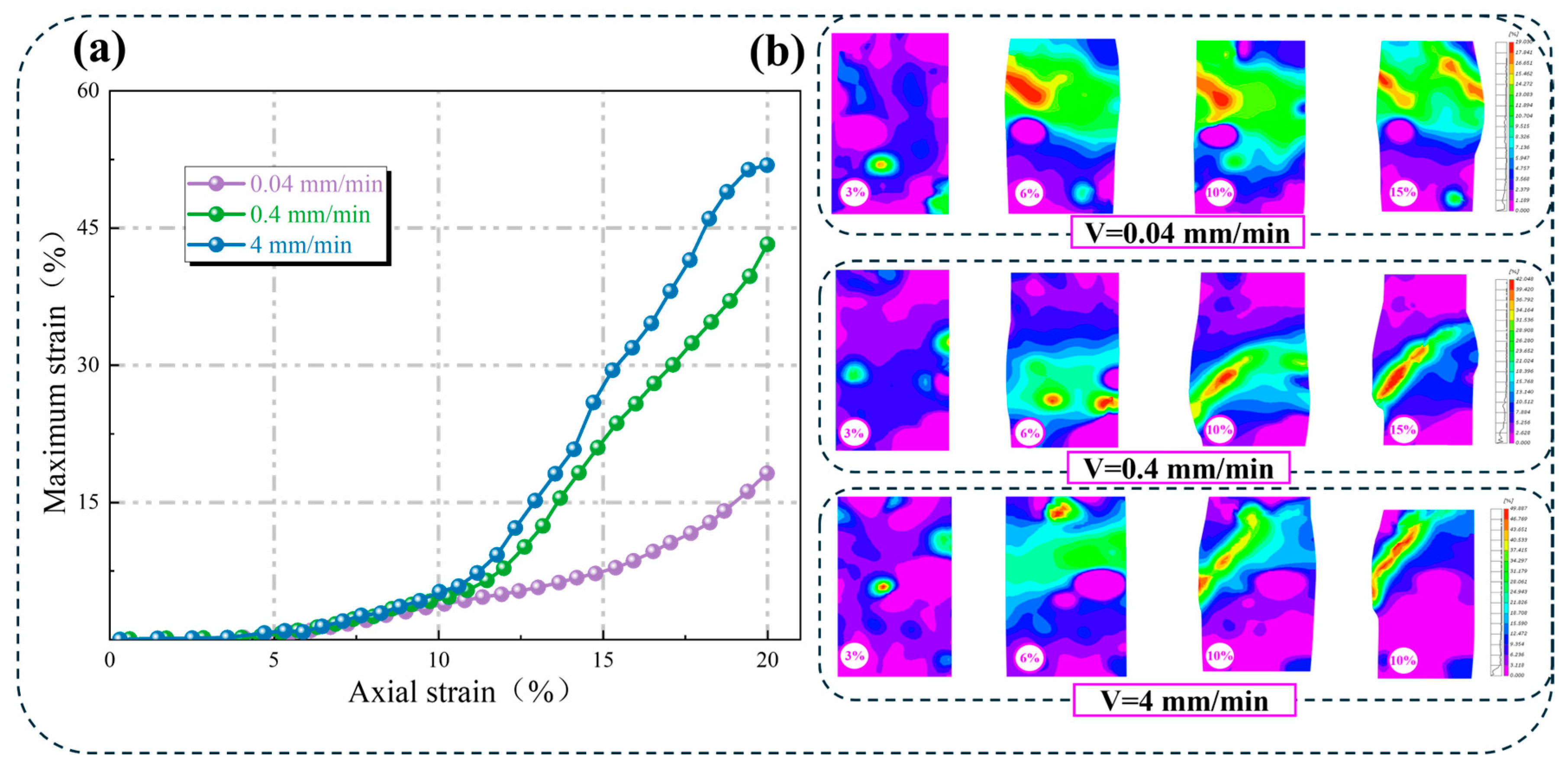
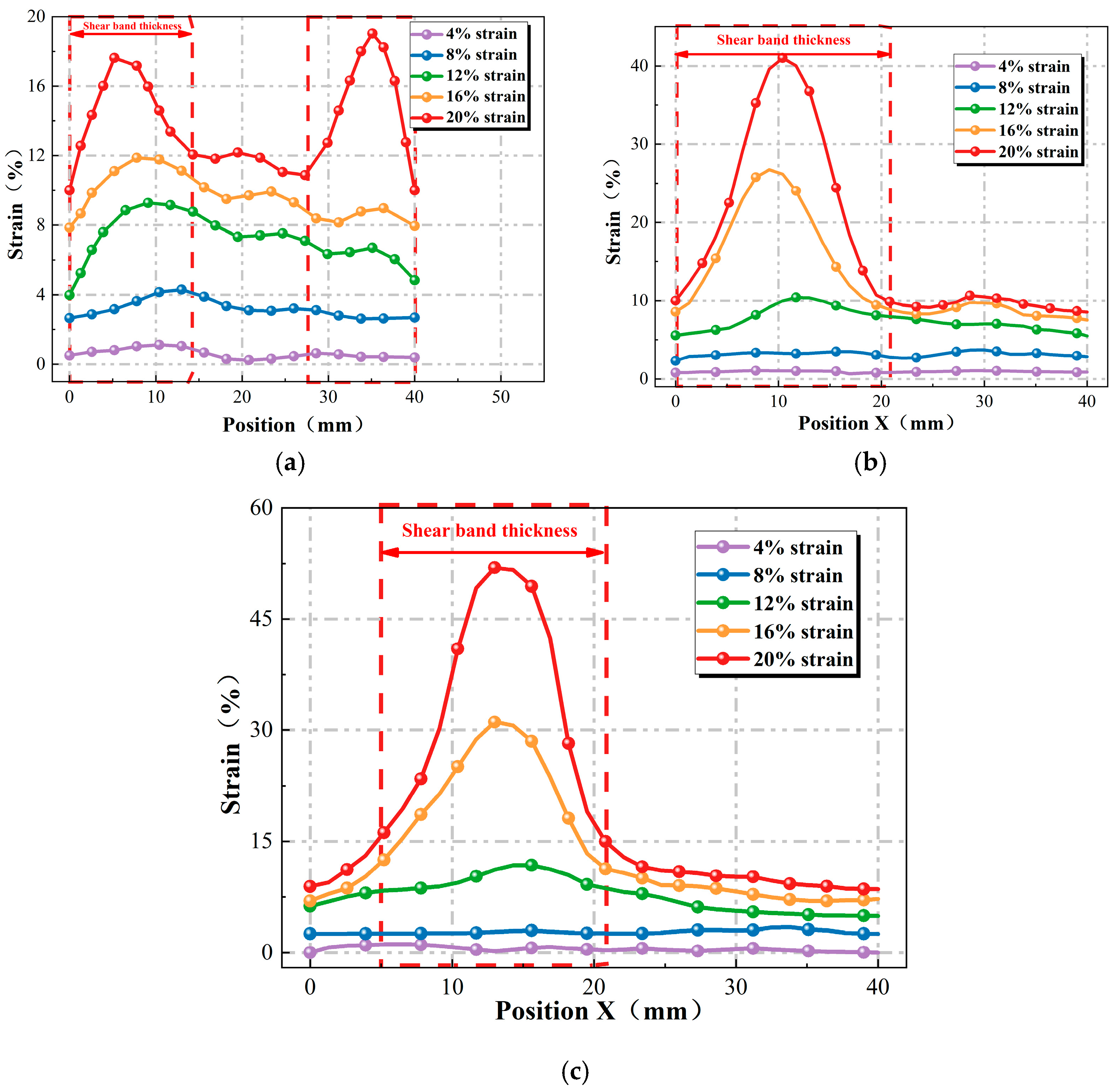
Figure 13 presents the peak strain distribution within shear bands, along with their evolutionary characteristics in stabilized silt across varying strain rate conditions. It can be observed from Figure 13a that a progressive reduction in the peak strain along the shear band of stabilized silt occurs with declining strain rates. The crack closure phase is gradually prolonged, with more energy accumulated during compression, while the other phases remain relatively unchanged. In the slow microcrack propagation phase, the energy dissipation from cementation bond fractures within the incipient shear band is counterbalanced by energy absorption in adjacent non-softened regions. This energy redistribution facilitates further strength enhancement until the specimen attains its peak shear resistance.
The initiation of strain localization under consolidated-undrained shear requires the development of an internal pore pressure gradient as its fundamental triggering mechanism [58,59]. With the formation and propagation of micro-cracks, partial soil particles enter a softening state, while the specimen as a whole remains in a hardening state. The specimen’s residual shear resistance, arising from intergranular friction and cementation bonds, effectively maintains particle stability during fracture closure while facilitating progressive pore pressure development. At elevated strain rates, the specimen exhibits localized disruption of drainage capacity, leading to suppressed volumetric deformation in the shear band. Concurrently, pore fluid in undrained specimens experiences enhanced confinement due to restricted flow pathways [60,61].
As shown in Figure 13b, the evolution of shear bands reveals that strain localization in stabilized silt initiates proximate to the peak strength, corresponding to approximately 6% axial strain. This observation aligns with the findings of Thakur [62], who reported consistent behavior in consolidated undrained triaxial tests carried out on silt samples. Meanwhile, the shear band of stabilized silt exhibits significant variations under different strain rates. At elevated strain rates, the fundamental shear band manifests as a highly localized deformation zone confined within a limited spatial domain, exhibiting failure characteristics typical of strain localization phenomena. As the strain rate decreases, this distinct strain localization phenomenon is mitigated. This is primarily attributed to the fact that a lower strain rate preserves the interparticle bonding structure of the soil, attenuates the strain softening effect of the stabilized silt, and facilitates the gradual formation of multiple cross-diffused cracks.
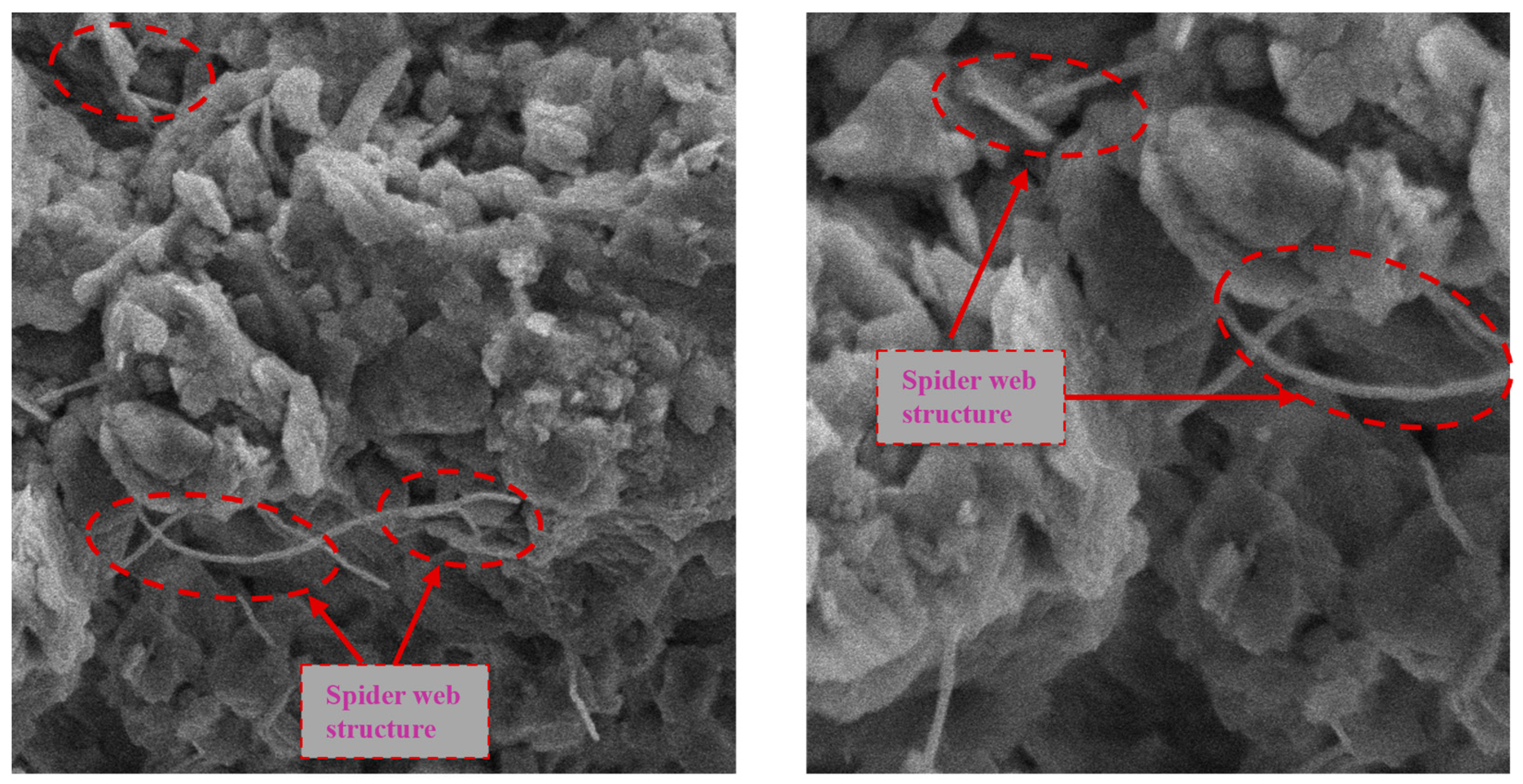
Yao et al. [53] concluded from their experiments that “X”-shaped shear bands are more likely to form when the strain rate is below 0.001%/min. A comparison with the findings of this study reveals that the weakening effect of the stabilized silt is more pronounced at lower strain rates, accompanied by the emergence of a more diffused spiderweb-like shear band. Scanning Electron Microscopy (SEM) observations revealed that the hydration products within the stabilized silt fill the pores in the form of “branch-like crystals,” establishing permanent chemical anchoring at the particle contact points. Each cementation node in the spiderweb-like structure is capable of independent micro-damage, which prevents abrupt stress changes along a single shear plane and gives rise to a “cobweb-effect “, as shown in Figure 14.

3.3.3. Thickness of Stabilized Silt Shear Band

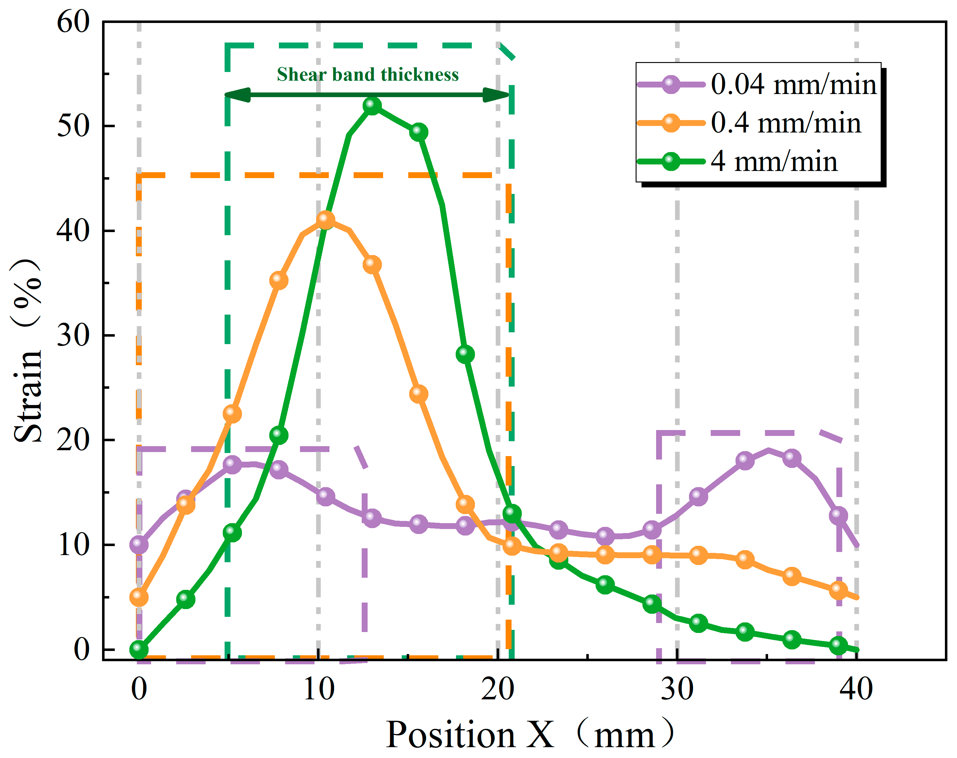
Particle rotation and slippage within soil constitute the primary mechanisms governing shear band deformation. As shown in Figure 13b, significant variations in shear band thickness are observed in stabilized silt under different strain rates. Soltanbeigi [63] proposed that the shear band boundaries can be made by identifying the strain localization points in the specimen. In this study, DIC was employed to analyze images of stabilized silt specimens under varying strain rates, with a focus on investigating the influence of strain rate on the shear band thickness of stabilized silt. The strain distribution characteristics along the critical section are illustrated in Figure 15, showing the response of stabilized silt specimens when subjected to different strain rates at peak strain conditions.
Experimental observations reveal the simultaneous formation of two distinct shear destruction zones when the specimen is subjected to quasistatic loading at 0.04 mm/min strain rate. At low strain rates, the sustained frictional and interlocking mechanisms between hydration products and soil particles in stabilized silt achieve full development. This process promotes substantial pore water pressure buildup within the specimen [64]. Subsequent dissipation of this pressure reinforces particle interlocking, thereby facilitating the expansion of shear band thickness. Under a strain rate of 4 mm/min, the shear band thickness of the sample is only 10 mm. Under high strain rates, the cohesive forces within stabilized silt dominate the mechanical behavior, leaving insufficient time for particle rotation and slippage. This results in non-uniform deformation of the specimen, exhibiting characteristic brittle failure patterns. The specimen exhibits a strength increment proportional to the substrate suction, analogous to the load-sharing mechanism observed in particle-reinforced composites [65]. Consequently, the experimental findings demonstrate that the thickness of the shear band diminishes with increasing strain rate, governed by the interplay of particle-scale kinematics (rotation and sliding) and the specimen’s pore water pressure dynamics.
Figure 16 shows the stress distribution curves of stabilized silt under different strain rates and strains. During the crack closure phase, the deformation of the entire specimen remains relatively homogeneous without shear band formation. As the crack propagation phase initiates, strain localization exhibits differential characteristics: under high strain rate conditions, localized strain zones develop rapidly, the dissipation of pore water pressure occurs more gradually, facilitating prolonged particle reconfiguration via intergranular displacement and shear-induced reorganization, and the development of strain in the specimen is relatively lagging behind [48]. This process improves the effective stress of the soil mass and suppresses the initiation of localized shear slip. Meanwhile, under sustained stress, the hydration product C-S-H gel in stabilized silt exhibits viscoelastic flow behavior. This phenomenon induces an autonomous reconfiguration of the cementation framework, thereby alleviating localized stress concentrations and subsequently suppressing the advancement of microcracks.
According to the maximum strain curve of the specimen in Figure 13a, the maximum strain reaches 49.89% under a strain rate of 4 mm/min. The maximum strain measurements demonstrate a notable loading rate dependency, with values decreasing by 16.1% at 0.4 mm/min and 61.8% at 4 mm/min when benchmarked against the reference strain obtained at 0.04 mm/min. A comparative analysis of Figure 13a and Figure 16 reveals an inverse relationship between shear band thickness and maximum strain localized within the band. At elevated strain rates, the shear band undergoes noticeable thinning, accompanied by a heightened strain energy accumulation rate per unit volume. This results in a significant increase in energy density within the shear band. This results in greater strain induced by energy release. At reduced strain rates, the stabilized silt exhibits pronounced interfacial adhesion between hydration phases and granular soil matrices, resulting in a sequential detachment behavior during shear deformation. The generated microcracks propagate across more cementation nodes, thereby restraining relative slippage among soil particles and resulting in reduced maximum strain. In the context of slope stability analysis, higher strain rates result in increased shear band deformation and greater failure strains, leading to more extensive slope failure. Investigating the development characteristics of shear bands under various strain rates can therefore facilitate the timely prediction of slope instability and help mitigate associated economic losses.

4. Conclusions

Based on DIC, this study conducted triaxial shear tests on stabilized silt to research the effects of strain rate on mechanical properties, failure modes, types of shear band development, and shear band thickness. The conclusions were drawn as follows:
(1)
A strength prediction model incorporating curing agent dosage and curing age was developed, effectively characterizing the strength development law of stabilized silt. The optimal content was determined to be 8%. As the curing agent dosage increases, the sensitivity of strain rate to the peak strength change rate of stabilized silt is enhanced, and a distinct lag effect of peak strain is observed under high strain rates.
(2)
The strain softening degree is sensitive to variations in strain rate and curing agent dosage, exhibiting a positive correlation with both factors. Specifically, at a curing agent dosage of 10%, an increase in strain rate from 0.04 mm/min to 4 mm/min results in a 33.79 kPa rise in strain softening degree. In contrast, the influence on pure silt is relatively minor.
(3)
Shear bands are a gradual process of development, and the development of shear bands in specimens can be obtained in three stages: crack closure stage, crack development stage, and crack slip stage; Under varying strain rates, changes occur in the internal energy dissipation and pore water pressure within the specimen, which in turn alter the development pattern of the shear band. Specifically, as the strain rate decreases, the development pattern of the shear band transitions from a single failure band to multiple diffuse bands.
(4)
The “spiderweb diffusion effect” of the shear band in stabilized silt under low strain rates is proposed. Compared with pure silt, the hydration products of stabilized silt form permanent chemical anchoring at interparticle contact points. Each cementation node within the spiderweb-like structure is capable of undergoing independent micro-damage, which mitigates stress mutations in the specimen.
(5)
Based on DIC, the shear band thickness and shear band characteristics of stabilized silt under varying strain rates were investigated. As the strain rate decreases, the cemented structure of the stabilized silt undergoes “adaptive adjustment,” which redistributes localized stress concentrations, retards the propagation of microcracks, and leads to a gradual increase in the thickness of the shear band. Compared with the maximum strain at a strain rate of 0.04 mm/min, the maximum strain along the shear band at strain rates of 0.4 mm/min and 4 mm/min decreased by 16.1% and 61.8%, respectively.
(6)
Actual slope failure processes often exhibit non-uniform velocity deformation. This study focuses on elucidating the evolution mechanism of shear bands under constant strain rates. Future work will extend this research to examine the development behavior of shear bands under variable strain rates and multiple influencing factors, thereby providing a theoretical foundation for predicting and addressing slope instability.

Author Contributions

Conceptualization, Z.Y.; data curation, writing—original draft, X.W.; project administration, Y.C. data curation, project administration, Y.Z.; supervision, H.D.; supervision, X.L. All authors have read and agreed to the published version of the manuscript.

Funding

This research was funded by the National Natural Science Foundation of China, grant number 42372327, and the National Natural Science Foundation of China, grant number 42177153.

Institutional Review Board Statement

Not applicable.

Informed Consent Statement

Not applicable.

Data Availability Statement

The original contributions presented in the study are included in the article, further inquiries can be directed to the corresponding author.

Conflicts of Interest

The authors declare no conflicts of interest.

References

  1. Wang, C.J.; Li, F.Y.; Guo, C.C. Mechanical properties and consolidation mechanism of polymer-solidified silt. J. Build. Mars. 2022, 25, 598–606. [Google Scholar] [CrossRef]
  2. Zhou, Q.Y.; Xiong, B.L.; Yang, G.Q.; Liu, W.C. Microstructure of Low Liquid Limit Silt. J. Geotech. Eng. 2013, 35, 439–444. [Google Scholar]
  3. Bai, J.H.; Yu, L.; Ye, X.F.; Yu, Z.B.; Wang, D.W.; Guan, Y.N.; Cui, B.S.; Liu, X.H. Dynamics of phosphorus fractions in surface soils of different flooding wetlands before and after flow-sediment regulation in the Yellow River Estuary. China J. Hydrol. 2020, 580, 124256. [Google Scholar] [CrossRef]
  4. Park, S.S.; Sung, S.W.; Nguyen, T.; Tran, D. Effect of silt uniformity on the liquefaction resistance of sand–silt mixtures. Soils Found. 2024, 64, 101507. [Google Scholar] [CrossRef]
  5. Li, J.D.; Zhang, Y.J.; Wang, X.; Jiang, D.J.; Wang, X.W. Research Status and Prospect of New Curing Agent Reinforcement of Expansive Soil. Mater. Rev. 2023, 37, 86–96. [Google Scholar] [CrossRef]
  6. Xu, F.; Cai, Y.B.; Qian, W.X.; Wei, H.; Zuang, H.X.; He, Y. Characterization and mechanism analysis of polynaphthalene sulfonate modified cemented soil. Constr. Build. Mater. 2020, 240, 117936. [Google Scholar] [CrossRef]
  7. Ding, L.Q.; Vanapalli, S.; Zou, W.L.; Han, Z.; Wang, X.Q. Freeze-thaw and wetting-drying effects on the hydromechanical behavior of a stabilized expansive soil. Constr. Build. Mater. 2021, 275, 122162. [Google Scholar] [CrossRef]
  8. Prakash, K.G.; Krishnamoorthy, A. Stability of embankment constructed on soft soil treated with soil cement columns. Transp. Infrastruct. Geotechnol. 2023, 10, 595–615. [Google Scholar] [CrossRef]
  9. Bian, X.; Wang, Z.F.; Ding, G.Q.; Cao, Y.P. Compressibility of cemented dredged clay at high water content with super-absorbent polymer. Eng. Geol. 2016, 208, 198–205. [Google Scholar] [CrossRef]
  10. Pu, S.Y.; Zhu, Z.D.; Wang, H.R.; Song, W.L.; Wei, R.J. Mechanical characteristics and water stability of silt solidified by incorporating lime, lime and cement mixture, and SEU-2 binder. Constr. Build. Mater. 2019, 214, 111–120. [Google Scholar] [CrossRef]
  11. Saidate, I.; Berga, A.; Rikioui, T. Stabilization of gypsum clay soil by adding lime. Civ. Eng. J. 2022, 8, 2511–2520. [Google Scholar] [CrossRef]
  12. Li, Y.; Su, L.; Ling, X.Z.; Wang, J.H.; Yang, Y.Z. Model studies on load-settlement characteristics of coarse-grained soil treated with geofiber and cement. Polymers 2018, 10, 621. [Google Scholar] [CrossRef]
  13. Zhu, J.F.; Tao, Y.L.; Xu, R.Q.; Yang, H.; Pan, B.J. Investigation on the optimal formulation and mechanism of marine organic silt improved with magnesium-cement- based stabilizer. Constr. Build. Mater. 2022, 341, 127233. [Google Scholar] [CrossRef]
  14. Sadek, Y.; Rikioui, T.; Abdoun, T.; Dadi, A. Influence of compaction energy on cement stabilized soil for road construction. Civ. Eng. J. 2022, 8, 580–594. [Google Scholar] [CrossRef]
  15. Wang, S.N.; Xue, Q.P.; Zhu, Y.; Li, G.Y.; Wu, Z.J.; Zhao, K. Experimental study on material ratio and strength performance of geopolymer-improved soil. Constr. Build. Mater. 2021, 267, 120469. [Google Scholar] [CrossRef]
  16. Mareya, M.; Tchadjie, L.; Sithole, T. Turning fly ash and waste gypsum into a resource for backfilling applications. Case Stud. Constr. Mater. 2024, 20, e02703. [Google Scholar] [CrossRef]
  17. Sukprasert, S.; Hoy, M.; Horpibulsuk, S.; Arulrajah, A.; Rashid, A.S.; Nazir, R. Fly ash based geopolymer stabilisation of silty clay/blast furnace slag for subgrade applications. Road Mater. Pavement Des. 2021, 22, 357–371. [Google Scholar] [CrossRef]
  18. Chen, R.M.; Jian, W.B.; Zhang, X.F.; Fang, Z.H. Experimental study on performance of sludge stabilized by CSFG-FR synergy. Rock Soil Mech. 2022, 43, 1020–1030. [Google Scholar]
  19. Huang, S.B.; He, Y.B.; Liu, X.W.; Xin, Z.K. Experimental investigation of the influence of dry-wet, freeze-thaw and water immersion treatments on the mechanical strength of the clay-bearing green sandstone. Int. J. Rock Mech. Min. Sci. 2021, 138, 104613. [Google Scholar] [CrossRef]
  20. Shen, K.Y. Experimental study on pressure sensitive properties of copper contaminated soil solidified by modified red mud. J. Environ. Eng. 2019, 27, 93–100. [Google Scholar] [CrossRef]
  21. Mozejko, C.A.; Francisca, F.M. Enhanced mechanical behavior of compacted clayey silts stabilized by reusing steel slag. Constr. Build. Mater. 2020, 239, 117901. [Google Scholar] [CrossRef]
  22. Sun, R.J.; Fang, C.; Gao, F.L.; Ge, Z.; Zhang, H.Z.; Lu, Q. Study on pavement performance and solidified mechanism of solidified soil based on solid waste. China J. Highw. Transp. 2021, 34, 216. [Google Scholar] [CrossRef]
  23. Kang, X.R.; Li, H.B.; Zhang, G.; Li, S.; Shan, L.; Zhao, J.; Zhang, Z. A Binary Medium Constitutive Model for Frozen Solidified Saline Soil in Cold Regions and Its Fractal Characteristics Analysis. Fractal Fract. 2024, 8, 33. [Google Scholar] [CrossRef]
  24. Shang, Y.Z.; Cui, Z.L.; Li, Y.J.; Zhang, Y.N.; Cheng, Y.H. Strength and Microscopic Mechanism of Cement–Fly Ash–Slag–Desulfurization Gypsum Solidified Mica Schist Weathered Soil. Materials 2023, 16, 6957. [Google Scholar] [CrossRef]
  25. Shu, H.; Yu, Q.B.; Niu, C.C.; Sun, D.; Wang, Q. The coupling effects of wet-dry and freeze–thaw cycles on the mechanical properties of saline soil synergistically solidified with sulfur-free lignin, basalt fiber and hydrophobic polymer. Catena 2024, 238, 107832. [Google Scholar] [CrossRef]
  26. Wang, X.B.; Zhang, N.; Pan, Y.S.; Du, Y.Z. Experimental study on Shear Zone Interaction and Damage of Uniaxial compressed cohesive Soil. Rock Soil Mech. 2018, 39, 1168–1175. [Google Scholar] [CrossRef]
  27. Thomas, T.Y. Plastic Flow and Fracture in Solids by Tracy Y Thomas; Elsevier: Amsterdam, The Netherlands, 1961. [Google Scholar]
  28. Chen, C.B.; Ye, G.L. Development of small-strain triaxial apparatus using LVDT sensors and its application to soft clay test. Rock Soil Mech. 2018, 39, 2304–2310. [Google Scholar] [CrossRef]
  29. Belmokhtar, M.; Delage, P.; Ghabezloo, S.; Conil, N. Drained triaxial tests in low-permeability shales: Application to the Callovo-Oxfordian claystone. Rock Mech. Rock Eng. 2018, 51, 1979–1993. [Google Scholar] [CrossRef]
  30. Cheng, Z.; Wang, J.F.; Coop, M.R.; Ye, G.L. A miniature triaxial apparatus for investigating the micromechanics of granular soils with in situ X-ray micro-tomography scanning. Front. Struct. Civ. Eng. 2020, 14, 357–373. [Google Scholar] [CrossRef]
  31. Salazar, S.E.; Barnes, A.; Coffman, R.A. Development of an internal camera–based volume determination system for triaxial testing. Geotech. Test. J. 2015, 38, 549–555. [Google Scholar] [CrossRef]
  32. Xu, J.; Wu, Z.P.; Chen, H.; Shao, L.T.; Zhou, X.G.; Wang, S.H. Triaxial shear behavior of basalt fiber-reinforced loess based on digital image technology. KSCE J. Civ. Eng. 2021, 25, 3714–3726. [Google Scholar] [CrossRef]
  33. Wang, P.P.; Guo, X.X.; Sang, Y.; Shao, L.T.; Yin, Z.N.; Wang, Y.D. Measurement of local and volumetric deformation in geotechnical triaxial testing using 3D-digital image correlation and a subpixel edge detection algorithm. Acta Geotech. 2020, 15, 2891–2904. [Google Scholar] [CrossRef]
  34. Batiste, S.; Alshibli, K.A.; David Suits, L.; Sheahan, T. Shear Band Characterization of Triaxial Sand Specimens Using Computed Tomography. Geotech. Test. J. 2004, 27, 568–579. [Google Scholar] [CrossRef]
  35. Li, C.S.; Kong, L.W.; Shu, R.J.; An, R.; Jia, H.B. Dynamic three-dimensional imaging and digital volume correlation analysis to quantify shear bands in grus. Mech. Mater. 2020, 151, 103646. [Google Scholar] [CrossRef]
  36. Li, C.S.; Kong, L.W.; Zhang, B.X.; Liu, Z.J.; Shu, R.J.; Li, T.G. Determination of damage evolution characteristics in granite residual soil shear bands by micro-CT-based advanced digital volume correlation. Eng. Geol. 2024, 333, 107505. [Google Scholar] [CrossRef]
  37. Liu, B.H.; Kong, L.W.; Li, C.S.; Wang, J.T. Evolution of shear band in plane strain compression of naturally structured clay with a high sensitivity. Appl. Sci. 2022, 12, 1180. [Google Scholar] [CrossRef]
  38. Su, D.; Wu, D.Z.; Fan, M.; Zhang, R.Q.; Chen, J.H.; Xiong, H.; Chen, X.S. DEM investigation into the coupling effects of particle asphericity and interface roughness on shear behaviour of soil-structure interface. Particuology 2025, 97, 39–57. [Google Scholar] [CrossRef]
  39. Ye, Z.T.; Gao, Y.F.; Shu, S.; He, X.C.; Sun, Y.F. Effects of Surface Roughness, Gradation, Relative Density, and Normal Stiffness on Global and Local Behaviors of the Sand–Steel Interface. J. Geotech. Geoenviron. Eng. 2025, 151, 04025078. [Google Scholar] [CrossRef]
  40. GB/T 50123-2019; Standard for geotechnical testing method. Ministry of Housing and Urban-Rural Development of the People’s Republic of China: Beijing, China, 2019.
  41. ASTM D2166; Standard Test Method for Unconfined Compressive Strength of Cohesive Soil. Ministry of Housing and Urban-Rural Development of the People’s Republic of China: Beijing, China, 2024.
  42. Zhang, T. Research on the Solidification and Improvement Technology and Engineering Application of Silt Based on Industrial By-Product Lignin; Southeast University: Nanjing, China, 2017. [Google Scholar]
  43. Yang, H.; Zhu, J.F.; Tao, Y.L.; Wang, Z.Q.; Zheng, Q.Q. Effect of the dry-wet cycle on the performance of marine waste silt solidified by calcium carbide residue and plant ash. J. Mar. Sci. Eng. 2022, 10, 1442. [Google Scholar] [CrossRef]
  44. Shang, Y.Z.; Cui, Z.L.; Zhang, Y.N. Experimental Study on the Synergistic Solidification of Soft Soil with Ceramic Powder–Slag–Phosphorus Slag. Sustainability. 2023, 15, 15474. [Google Scholar] [CrossRef]
  45. Chen, Z.; Xu, H.C.; Cheng, M.Y.; Lu, H.W.; Wang, Z.J.; Feng, P.Y. Dynamic triaxial test and microscopic study of solidified muddy soil with different mixing ratios and curing ages. Front. Mater. 2021, 8, 731449. [Google Scholar] [CrossRef]
  46. Chen, M.L.; Wu, D.Z.; Chen, K.Y.; Cheng, P.R.; Tang, Y.H. The influence of fly ash-based geopolymer on the mechanical properties of OPC-solidified soil. Constr. Build. Mater. 2024, 432, 136591. [Google Scholar] [CrossRef]
  47. Wang, H.B.; Ren, H.; Zhang, X.J.; Sun, W.C.; Xu, F.; Luo, A.J.; Xu, W.J. The influence of fine-grained soil and loading rate on the mechanical behavior of soil-rock mixtures. Hydrogeol. Eng. Geol. 2024, 51, 86–92. [Google Scholar] [CrossRef]
  48. Su, C.D.; Li, H.Z.; Zhang, S.; Gou, P.F. Experimental investigation on the effect of Strain Rate on the Mechanical Properties of Marble. J. Rock Mech. Eng. 2013, 32, 943–950. Available online: https://rockmech.whrsm.ac.cn/CN/abstract/abstract28122.shtml (accessed on 19 November 2012).
  49. Zhou, R.X. Research on the Influence of Strain Rate on the Localization of Planar Strain in Frozen Sand. Master’s Thesis, Xi'an University of Technology, Xi'an, China, 2024. [Google Scholar] [CrossRef]
  50. Cai, Y.; Kong, L.W.; Guo, A.G.; Tuo, Y.F. The influence of shear strain rate on the mechanical properties of strong structural clay in Zhanjiang. Geotech. Mech. 2006, 8, 1235–1240. [Google Scholar]
  51. Xu, X.T.; Wang, Y.B.; Yin, Z.H.; Zhang, H.W. Effect of temperature and strain rate on mechanical characteristics and constitutive model of frozen Helin loess. Cold Reg. Sci. Technol. 2017, 136, 44–51. [Google Scholar] [CrossRef]
  52. Gylland, A.S.; Jostad, H.P.; Nordal, S. Experimental study of strain localization in sensitive clays. Acta Geotech. 2014, 9, 227–240. [Google Scholar] [CrossRef]
  53. Yao, X.L.; Wang, W.L.; Zhang, M.Y.; Wang, S.H.; Wang, L.P. Strain localization of a frozen sand under different test conditions. Cold Reg. Sci. Technol. 2021, 183, 103226. [Google Scholar] [CrossRef]
  54. Gong, L.X.; Nie, L.; Xu, Y. Discrete Element Analysis of the Strength Anisotropy of Fiber-Reinforced Sands Subjected to Direct Shear Load. Appl. Sci. 2020, 10, 3693. [Google Scholar] [CrossRef]
  55. Shi, C.; Yang, J.X.; Chu, W.J.; Tang, H.; Zhang, Y.P. Macro-and micromechanical behaviors and energy variation of sandstone under different unloading stress paths with DEM. Int. J. Geomech. 2021, 21, 04021127. [Google Scholar] [CrossRef]
  56. Lu, X.B.; Wang, S.Y.; Peng, C. On the evolution of simple shear in saturated soils. Int. J. Numer. Anal. Methods Geomech. 2004, 28, 269–278. [Google Scholar] [CrossRef]
  57. Li, Z.; Wang, Y.H.; Ma, C.H.; Mok, C.M.B. Experimental characterization and 3D DEM simulation of bond breakages in artificially cemented sands with different bond strengths when subjected to triaxial shearing. Acta Geotech. 2017, 12, 987–1002. [Google Scholar] [CrossRef]
  58. Vardoulakis, I. Deformation of water-saturated sand: II. Effect of pore water flow and shear banding. Géotechnique 1996, 46, 457–472. [Google Scholar] [CrossRef]
  59. Sulem, J.; Vardoulakis, I. Bifurcation Analysis in Geomechanics; CRC Press: Boca Raton, FL, USA, 1995. [Google Scholar] [CrossRef]
  60. Jostad, H.; Andresen, L.; Thakur, V. Calculation of shear band thickness in sensitive clays. Numer. Methods Geotech. Eng. 2006, 1, 27–32. [Google Scholar] [CrossRef]
  61. Thakur, V. Numerically observed shear bands in soft sensitive clays. Geomech. Geoengin. 2011, 6, 131–146. [Google Scholar] [CrossRef]
  62. Thakur, V. Strain Localization in Sensitive Soft Clays. Ph.D. Thesis, Norwegian University of Science and Technology, Trondheim, Norway, 2007. [Google Scholar]
  63. Soltanbeigi, B.; Adlen, A.; Cinicioglu, O. Influence of dilatancy on shear band characteristics of granular backfills. Eur. J. Environ. Civ. Eng. 2021, 25, 1201–1218. [Google Scholar] [CrossRef]
  64. Menon, S.; Song, X. Shear banding in unsaturated geomaterials through a strong nonlocal hydromechanical model. Eur. J. Environ. Civ. Eng. 2022, 26, 3357–3371. [Google Scholar] [CrossRef]
  65. Lu, N.; Likos, W.J. Unsaturated Soil Mechanics; John Wiley and Sons, Inc.: Hoboken, NJ, USA, 2004. [Google Scholar] [CrossRef]
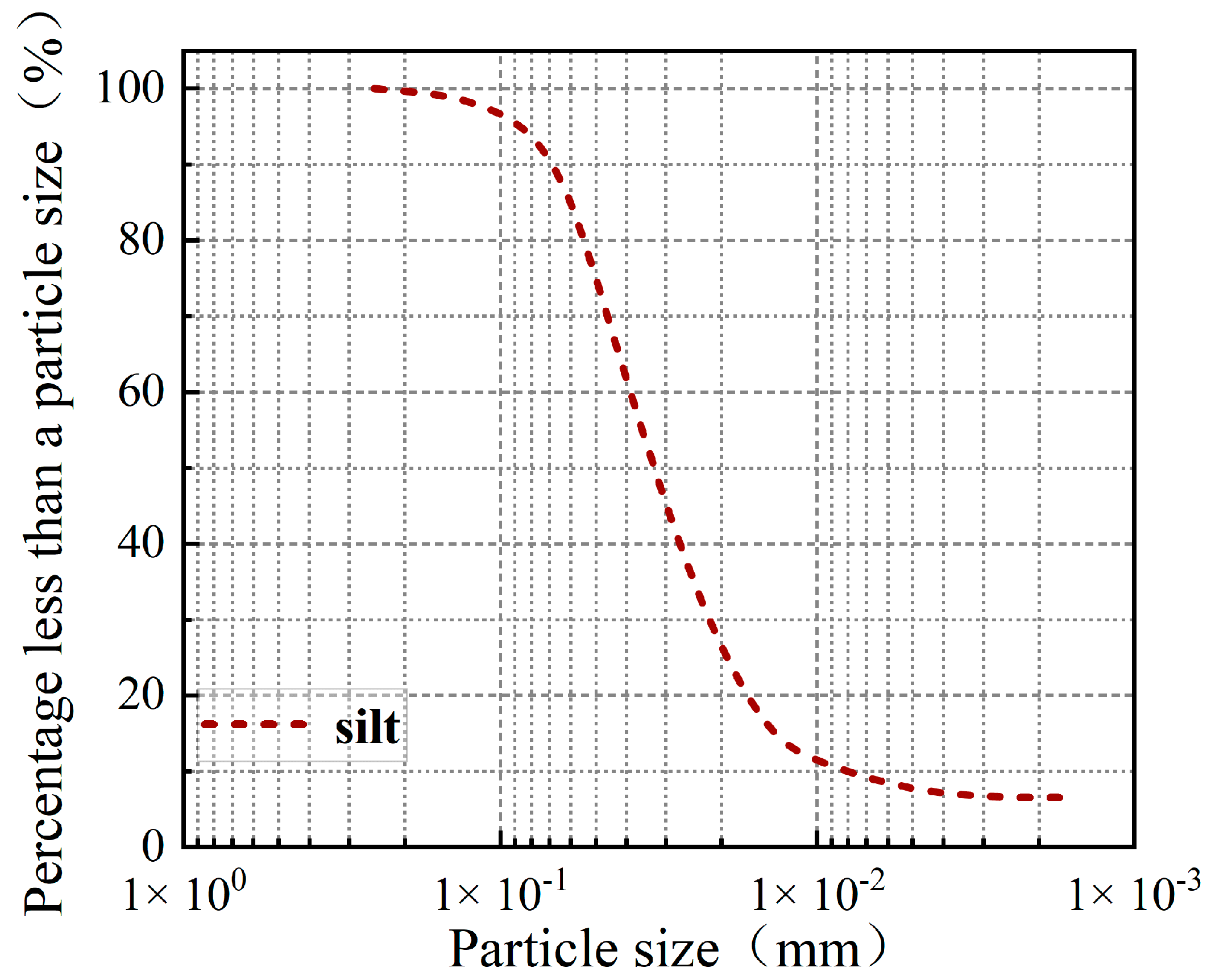
Figure 1. Particle distribution curve for silt.
Applsci 15 10128 g001
Figure 2. Flowchart of the test.
Applsci 15 10128 g002
Figure 3. Flowchart of XTDIC Technique.
Applsci 15 10128 g003
Figure 4. UCS of Stabilized Silt.
Applsci 15 10128 g004
Figure 5. Stress–strain curves of stabilized silt: (a) 0%; (b) 2%; (c) 4%; (d) 6%; (e) 8%; (f) 10%.
Applsci 15 10128 g005aApplsci 15 10128 g005b
Figure 6. Relationship between strain softening degree of stabilized silt and dosage of curing agent, strain rate.
Applsci 15 10128 g006
Figure 7. Relationship between peak strength of stabilized silt and dosage of curing agent, strain rate.
Applsci 15 10128 g007
Figure 8. The peak strength change rate and fitting line of stabilized silt under different strain rates.
Applsci 15 10128 g008
Figure 9. Stress–strain relationships and failure modes of stabilized silt.
Applsci 15 10128 g009
Figure 10. (a) Evolution of bonding failure in stabilized silt. (b) Influence of strain rate on failure modes of stabilized silt.
Applsci 15 10128 g010
Figure 11. (a) Maximum transverse strain of the specimen. (b) Experimental model diagram; (c) Schematic diagram of sample cracks. (d) Strain field of the specimen.
Applsci 15 10128 g011
Figure 12. Process diagram of cracking in stabilized silt.
Applsci 15 10128 g012
Figure 13. (a) Maximum strain on the shear band at different strain rates and (b) development law of shear band.
Applsci 15 10128 g013
Figure 14. SEM image of stabilized silt.
Applsci 15 10128 g014
Figure 15. Strain distribution of the cross-section where the maximum strain point of the specimen is located at different strain rates.
Applsci 15 10128 g015
Figure 16. Maximum strain variation curve of stabilized silt: (a) 0.04 mm/min; (b) 0.4 mm/min; (c) 4 mm/min.
Applsci 15 10128 g016
Table 1. Basic physical properties of silt.
Optimal Moisture
Content/%
Maximum Dry
Density g/cm3
Liquid
Limit/%
Plastic
Limit/%
Specific
Gravity
Plasticity
Index
17.701.6229.6420.362.709.28
Table 2. Test scheme for UCS of solidified silt.
Sample NumberCuring Agent Content (%)Strain Rate (mm/min)Sample NumberCuring Agent Content (%)Strain Rate (mm/min)
M100.04M1060.04
M20.4M110.4
M34M124
M420.04M1380.04
M50.4M140.4
M64M154
M740.04M16100.04
M80.4M170.4
M94M184
Disclaimer/Publisher’s Note: The statements, opinions and data contained in all publications are solely those of the individual author(s) and contributor(s) and not of MDPI and/or the editor(s). MDPI and/or the editor(s) disclaim responsibility for any injury to people or property resulting from any ideas, methods, instructions or products referred to in the content.