1. Introduction
The management of thermal energy within specific temperature regimes is a cornerstone of advanced engineering and scientific endeavors. This report focuses on the principles, design, and applications of cryopanels, cryoheat exchangers, and general cooling surfaces operating within the temperature range of 80 K to 300 K. This span is particularly significant as it bridges ambient conditions (approximately 300 K) with the upper thresholds of the cryogenic spectrum, typically defined as temperatures below 123 K or even below 100 K [
1]. The ability to precisely control temperatures within this range is crucial for a diverse array of industrial, scientific, and emerging technologies.
Cryopanels are a type of heat exchanger used in cryogenic technology across various scientific fields, including medicine and physics, as well as in industrial applications in the food industry and electronics. The authors [
2,
3] note that cryopanels are used to store and study samples at low temperatures. In the work of the authors [
2], they study structural transitions from a liquid-solid to a lamellar-crystalline state and organic glasses by condensing methanol at 132 K and cooling to 83 K. The authors [
3] study thin films and the recondensation of methanol in a nitrogen matrix, recording IR spectra from 45 K to 180 K. In biological research [
4], samples for biological electron microscopy are frozen and maintained at temperatures of up to 98 K. In electronics [
5], cryogenic technologies and liquid nitrogen cooling are used to create and improve semiconductors, as well as to cool the cores of high-current cables and superconducting conductors. In Ref. [
5], the possibility of an optimal cooling process for the cores of ultra-fast charging cables at temperatures of up to 80 K was explored. The food industry [
6] is exploring methods for storing products at low temperatures, including cryogenic techniques, such as shock freezing for berries and their subsequent drying. In [
7], the effect of different freezing temperatures with liquid nitrogen (148–238 K) on the quality of ice crystals and muscles of white shrimp was studied. However, long freezing times or high consumption of cooling liquid may harm the economics of food production or its quality. The examples described above used liquid nitrogen in direct contact with the samples in their studies, which does not control the consumption of liquid nitrogen and the resulting final temperatures. Currently, cryopanels are large and inconvenient to use. A compact and portable system would be preferable. In [
8], measurements of liquid nitrogen flow were conducted over 40 cm. Depending on the design of the cryo exchanger, the sizes can be up to 20 square meters for industrial samples [
9,
10].
Studying the physical and thermal properties of cooling using liquid nitrogen enables us to enhance cooling technologies and mass production, as well as to develop complex, universal cooling methods that span from room to cryogenic temperatures (80–300 K). This is due to the search for new technological solutions and the miniaturization of technologies without compromising energy efficiency [
11,
12].
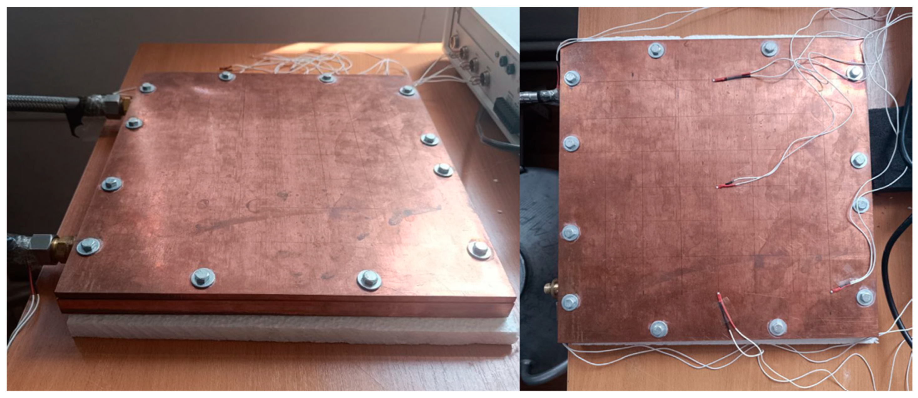
We are considering the development of a new design of a universal cryopanel suitable for the fields of electronics, physics, materials science, biology, and the food industry, where temperature maintenance and cooling from 300 K to 80 K are required. This cryopanel will be smaller in size (34 by 34 cm) and will require less coolant since it uses cold gaseous nitrogen instead of liquid nitrogen. The prefabricated design and small volume of the coolant storage tank (liquid nitrogen) ensure the mobility of the installation units, resulting in reduced operating and economic costs [
13]. The design of cryopanels, particularly the strategic deployment of louvers, baffles, and multi-stage cooling, exemplifies a sophisticated, multi-layered approach to heat load management. The paramount challenge in maintaining cryogenic temperatures is the continuous ingress of parasitic heat from the warmer environment. Louvers and baffles, actively cooled by the first stage, serve as initial thermal barriers. They intercept radiant heat from the ambient vacuum chamber and condense the majority of high-vapor-pressure gases (like water and CO
2) at a relatively warmer temperature [
14]. This strategic layering minimizes the thermal burden on the coldest, most energy-intensive stages of the cryopump, directly contributing to the overall efficiency and sustained performance of the system.
Furthermore, cryopanel design incorporates deliberate surface treatments to optimize both thermal shielding and gas capture. While the outer surfaces of components like the 80 K shield are typically specularly finished to reflect radiant heat from the room temperature environment [
15].
The effectiveness of cryopanels is characterized by several key performance metrics, which are central to their design and optimization. Cooldown time refers to the duration required for the cryopanels to reach their operational cryogenic temperatures. This is influenced by factors such as the initial rough pumping pressure and the composition of residual gases in the chamber [
15]. Pumping speed quantifies the volumetric flow rate at which gas is removed from the vacuum chamber. It is directly influenced by the thermal energy of the gas molecules and the effective inlet area of the pump. Pumping speed for gases like nitrogen in the molecular flow region typically remains constant [
16].
Optimization efforts in cryopanel design primarily focus on maximizing pumping speed and capacity while simultaneously minimizing these various heat loads. This involves careful sizing of the cryopanels, optimizing the design of louvers and baffles to reduce radiant heat transfer.
Furthermore, the continuous management of thermal loads—including radiant heat, the heat of condensation, and conducted heat—is paramount for sustaining the cryopanel’s low operating temperature and, consequently, its pumping efficiency and capacity over time. Any increase in these heat loads can cause the cryopanels to warm, leading to a reduction in pumping speed and overall capacity. This underscores that the operational performance of a cryopump is not static but is intrinsically linked to its ability to manage thermal energy input effectively [
17].
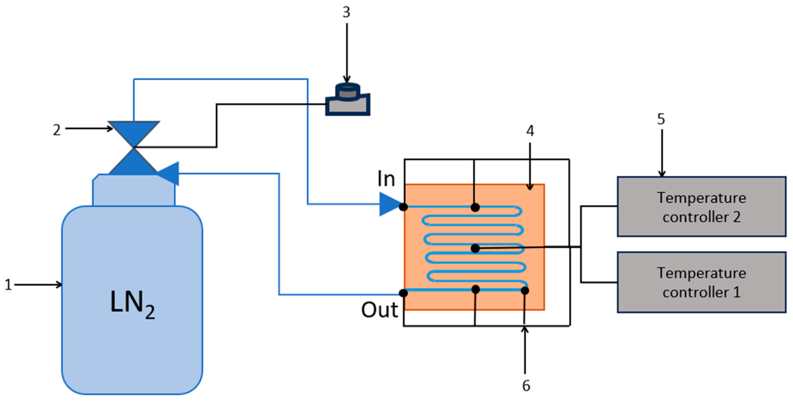
The proposed approach is based on cooling the panels using cooled nitrogen, which flows through channels between two plates in very close contact [
18,
19]. The prefabricated design is universal and variable in its choice of material for the upper and lower plates, eliminating the need for additional insulation. Replacing only one part in the event of internal damage will reduce manufacturing and repair costs.
The approach was substantiated using a computer modeling method widely used to solve problems in various fields, including two-phase and nanofluid flows [
20]. The computer modeling method enables a rapid and cost-effective examination of changes in geometric parameters and operating modes, eliminating the need for expensive prototypes [
21]. At the same time, operational tests were conducted on a finished prototype of a universal cryopanel. The data obtained will enable the improvement of a computer model for studying thermal conductivity and cooling of cryopanels using gaseous and liquid nitrogen.
3. Results and Discussion of the Experiment
The experiments were carried out under normal room temperature conditions of 300 ± 2 K. The experiment typically lasts 40–45 min on average. By the 30th minute, the cryopanel has cooled down to 150 K.
Figure 4 illustrates how the average surface temperature of the cryopanel decreases from 300 K to 93 K. The cooling rate is on average 0.0828 K/s. The minimum deviations in measurements of the average temperature on the surface of the cryopanel are ±5 K. The discrepancies of 10–20 K at the beginning and end of the nitrogen flow channel could be influenced by external conditions such as room temperature, heat inflows from the environment, and different nitrogen feed rates at the initial stages of launch.
The first stages of the setup and experiments on cooling the cryopanel were carried out at the minimum possible feed rates of cooled gaseous nitrogen, having a temperature of about 80 K.
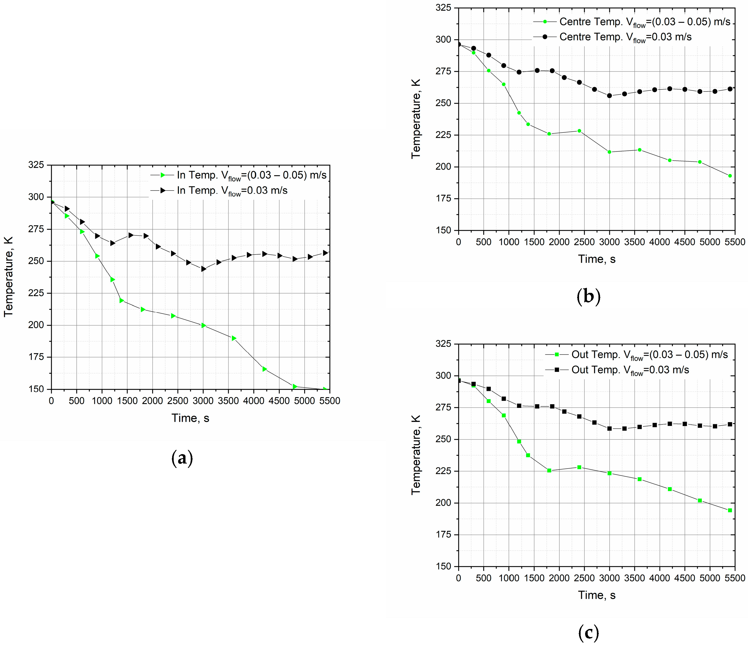
Figure 5a shows how the temperature at the cryopanel inlet changes. In the first case (black mark), the minimum possible supply speed of nitrogen is 0.03 m/s. The temperature changes very slowly, 0.016 K/s. This mode is susceptible to external heat inflows; cooling to cryogenic temperatures is almost not achieved (
Figure 5a–c). In the second case (green mark), the flow rate gradually increased from 0.03 to 0.05 m/s. The cryopanel temperature decreases to 150 K in 100 min. More than 2 h may be required to cool the entire cryopanel under this operating mode.
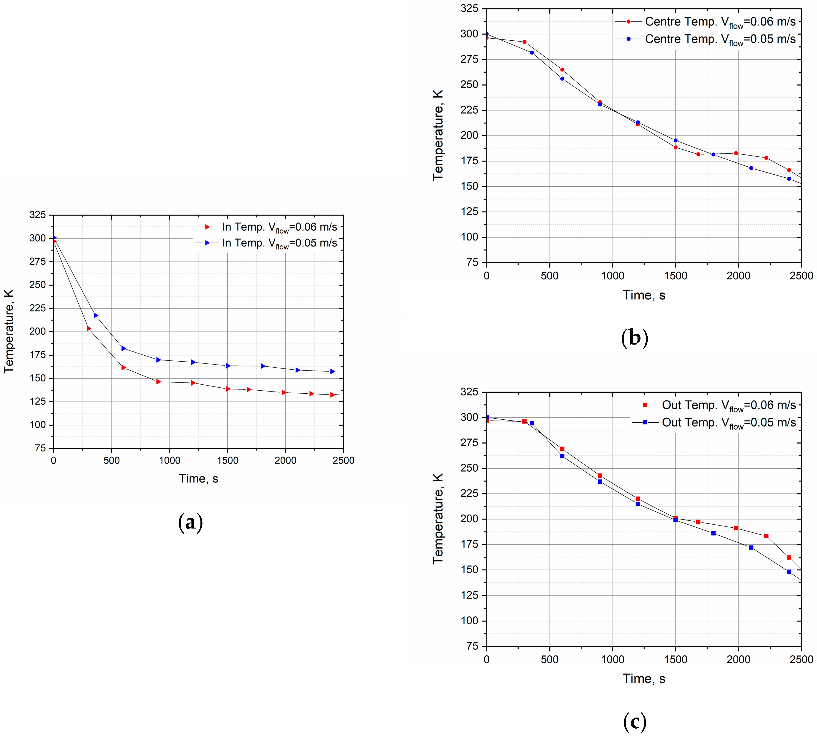
Then, experiments were conducted at the maximum possible nitrogen supply speed (
Figure 6a–c). No cryopanel tests were conducted above these rates because when the flow rate increases above 0.06 m/s, deformation of the upper plate of the cryopanel is observed under the pressure of the supplied nitrogen. This not only comprises mechanical damage to the plate, but also a large leak of nitrogen at the joints and seams of the cryopanel. As can be seen from
Figure 6b,c, at the limiting values of the flow rate (0.05–0.06 m/s), the cryopanel cools by 0.07 K per second, and the experiment is reproducible. In the center, the cryopanel cools to the specified 150 K in 41 min.
4. Computer Modeling
To prepare for experiments and a prototype of the cryopanel, it was decided to carry out preliminary modeling of its operation. Below, we will present the theory of the cryopanel modeling method, which predicted the cooling of the cryopanel with cooled nitrogen.
4.1. Theory and Simulation Methods
To simulate the cooling of a cryopanel, the nodal equations are based on the description of heat exchange through conduction, convection and radiation. Depending on the tasks, combinations of the above processes in the Comsol Multiphysics version 6.1 software package and their solution by the finite element method (FEM) and computational fluid dynamics (CFD) [
25] are possible. In the process of modeling, we mainly used the capabilities of the combination of the solvers “Heat transfer in solids”, “Laminar flow” and “Heat transfer in liquid/gas”.
Thermal conductivity is more pronounced in the solid medium of the cryopanel, and the rate of thermal energy transfer is higher. The equation for thermal conductivity is as follows [
26]:
where
ρ is the density,
C is the heat capacity,
T is the temperature,
k is the thermal conductivity,
Q is the heat source. In our case, we do not consider the presence of an internal heat source; therefore,
Q = 0 W.
The laws of conservation of mass, momentum, and energy are used to model fluid motion and heat transfer. The following equation applies to flow dynamics [
27,
28]:
where
ρ is the density,
ui is the velocity component along
i,
Fi is the external component of the force along
i,
μ is the dynamic viscosity of the gas.
For flow line channels, several non-circular cross-sectional shapes can be considered. Injecting fluid flow through these geometries is often difficult due to their irregular shape. Using the hydraulic diameter
Dh is a method for approximating flows through these geometries [
29,
30]:
For gas flows in long, straight flow lines of constant cross-section, the Reynolds number gives a good indication of whether turbulence will occur. It is given by:
Here, Dh is the hydraulic diameter, η and ν are the dynamic and kinematic viscosity, respectively.
The Reynolds numbers under consideration do not exceed the critical value (Recrt = 2300) for the considered sections of the coolant flow channel; the flow can be regarded as laminar. Laminar flow must be ensured to eliminate flow beating and stress on the upper plate of the cryopanel, which will affect its tightness.
4.2. Boundary Conditions and Model Construction
Three main types of thermal boundaries were included in this simulation. The outer boundaries of the upper plate are not thermally insulated and were in contact with the ambient environment at room temperature. The lower plate is thermally insulated.
Table 1 indicates the boundary conditions of the numerical experiment. The channel inlet is set as the flow velocity boundary with a value of 0.05 m/s. This velocity will give a laminar flow. The flow is not pushed through the channel. The target pressure at the inlet was set to 2 bar (0.2 MPa), while at the outlet it was defined as atmospheric. For the thermal boundary conditions, the inlet and outlet temperatures were set to 80 K, and the wall temperature was set to 300 K, since it had no thermal insulation.
The initial and boundary parameters fix the operating conditions of the cryopanel being developed. The solvers of the Comsol Multiphysics version 6.1 software environment are suitable for solving differential equations from the modeling theory described earlier; now, we proceed to building the model.
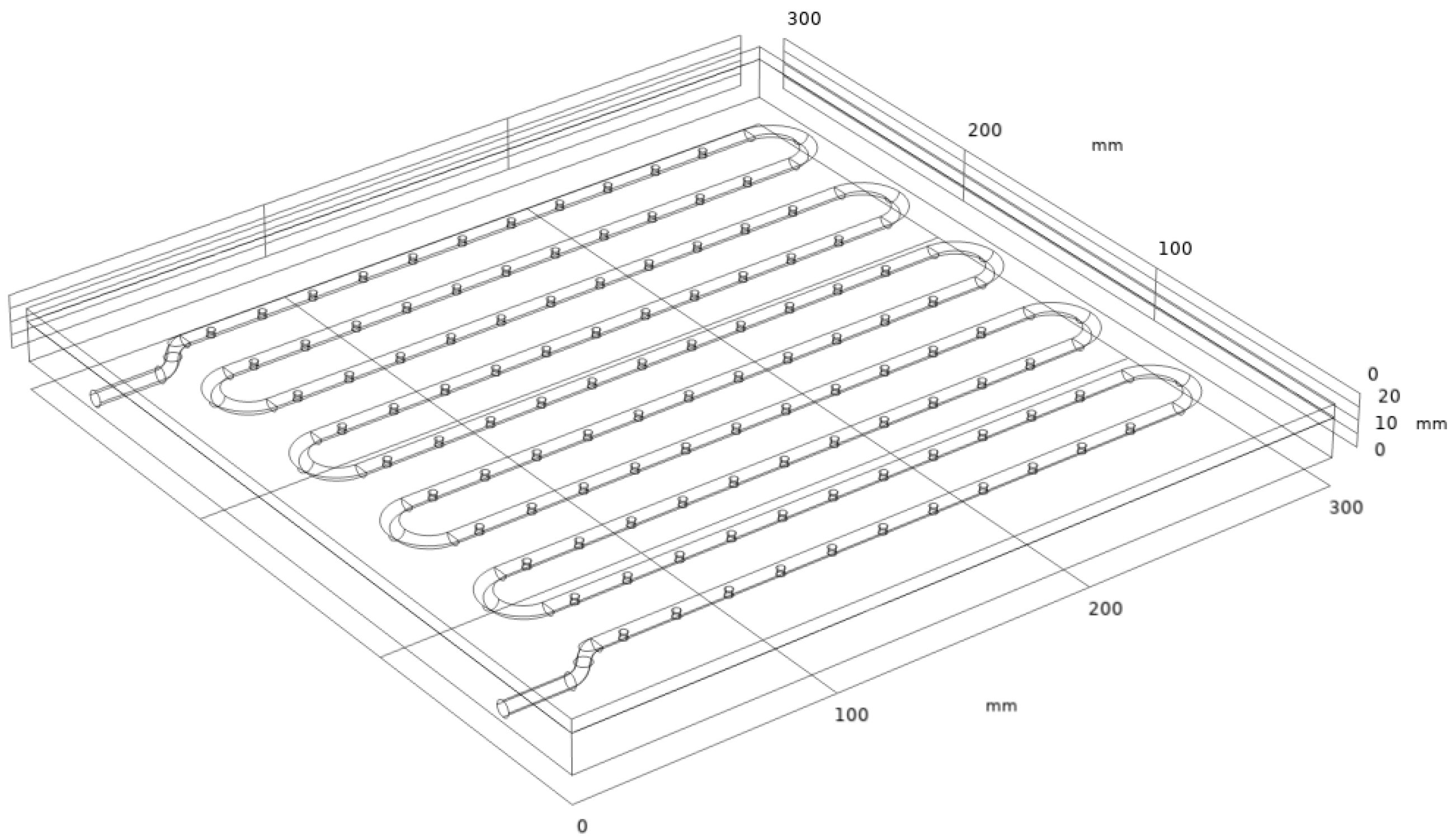
First, a 3D model (
Figure 7) of the cryopanel being developed was created according to the design presented in
Figure 3.
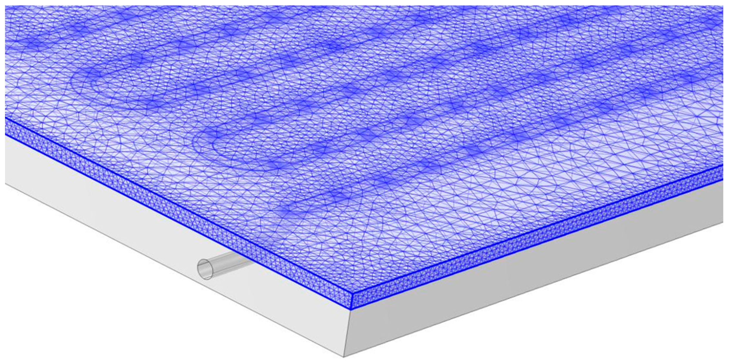
The cooled nitrogen flow region and the cryopanel volume were represented by the polygonal cellular zones shown in
Figure 8. The calculated mesh of the model consisted of 858,357 polygonal elements, 74,450 boundary elements, and 7899 edges. Depending on the size and shape of the cells, these values may vary.
In this work, simulations were performed using models describing the dynamics of gas flow and heat exchange in a gas–solid system. All simulations were performed using Comsol Multiphysics 6.1 [
31,
32]. Post-processing of the results was performed using OriginPro 2019.
4.3. Analysis of Simulation Results
Temperature measurements at the inlet, outlet and centre of the cryopanel showed that the temperature was uneven.
Figure 9 shows the results of temperature measurements at the control points at the inlet to the cryopanel nitrogen channel, at the outlet from the channel, and at the centre of the working upper surface of the cryopanel. The experimental results (
Figure 9a) show that a sharp decrease in temperature is observed at the inlet of the cryopanel. In contrast, at the outlet and in the centre of the panel, the temperature decrease has the same rate. The simulation results (
Figure 9b) and the assessment of its adequacy and verification are provided for comparison. As the simulation showed, the temperature in the centre of the cryopanel by 2500 is comparable with the experimental results. However, there is no such sharp drop in temperature at the inlet and outlet. What could be the reason for this?
In the experiment, at the entrance to the cryopanel (
Figure 9a), a sharp drop in temperature is observed, which slows down by the 1000th second of the experiment. One of the reasons for the difference between the model and the experiment is the heat inflows of the environment, and not a heat-insulated system as in the model. Another reason is the non-stationary temperature of nitrogen at the entrance, which can also change over time. The model does not take into account that nitrogen has time to heat up while passing through the pump and pipeline before entering the cryopanel. At the channel outlet, the temperature experiment shows a cooling trend for 1300 s, similar to the one in the center of the cryopanel. Also, if we look again at
Figure 9a which also show an advance in temperature decrease from the central part of the cryopanel at 2280 s. We, the authors, associate this decrease with a loose fit of the upper plate of the cryopanel and a probable leakage of nitrogen under the plate, bypassing the channel. In the range of 175–200 K, compression of the insulating material at the joints probably occurs and nitrogen leakage is observed along the edges of the cryopanel.
Thus, the model describes ideal conditions for cooling the cryopanel and does not take into account some particular conditions of operation of the cryopanel, as shown in the experiment. The current relative error of the model is 0.31 at the input to the cryopanel, 0.11 in the center, and 0.12 at the output. The model needs to be improved in the first section of the channel. In this case, it is recommended to modify the solution in the initial section at the entrance to the cryopanel, or set the temperature change according to the dependence obtained from the experimental data.
At the moment, there are technical problems with the cryopanel: it is necessary to solve the issue of complete thermal insulation at the bottom of the panel and the solution of nitrogen leakage through the joints between the plates. After improving the design, it is recommended to repeat the experiments and evaluate the adequacy of the model.
4.4. Justification of the Cryopanel Geometry
To justify the design of the turbulator, a simulation was performed, considering a segment of the cryopanel prototype, which included a channel 230 mm long and 3 mm in radius.
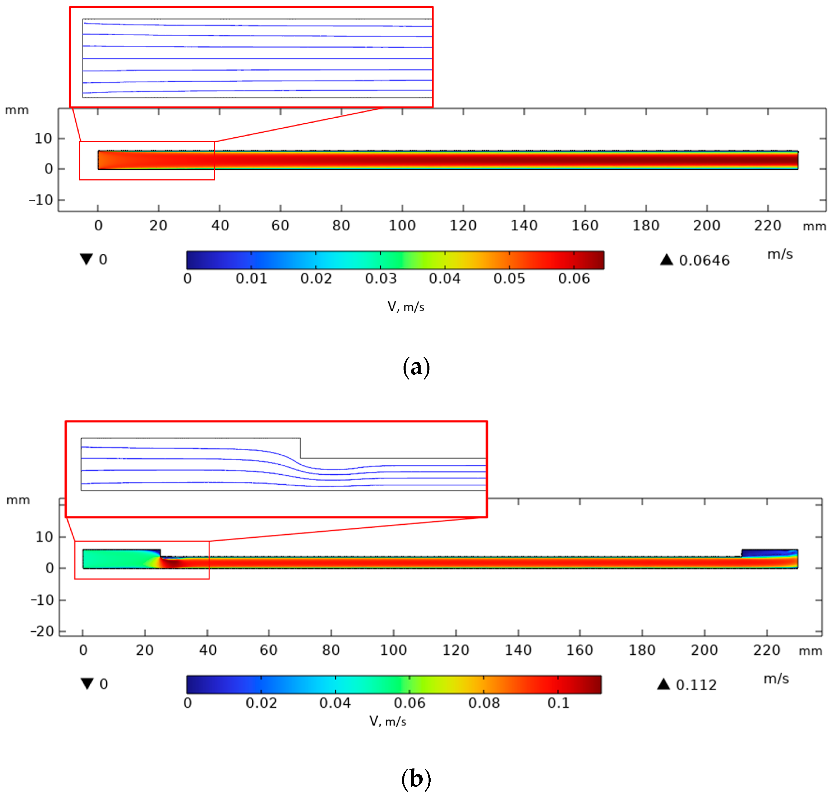
In the Comsol Multiphysics 6.1 environment, within the Laminar Flow solver in a 2D channel section, the velocity and streamlines of the nitrogen flow were estimated. Three types of channel profile geometry were taken as the modeling object. In the first case, a simple prefabricated cryopanel with a semicircular channel, 3 mm in radius, consisting of an upper and lower plate, was considered. The upper plate is thin and flat without modifications. As can be seen from the original simulation (
Figure 10a–c), the channel geometry will affect the liquid nitrogen flow rate at the inlet. In
Figure 10a, judging by the streamlines, a laminar flow is shown and a slight increase in velocity at the outlet from 0.05 to 0.0646 m/s. Along the channel walls, the flow velocity is zero.
If a wedge (with a height of 2.3 mm and a width of 3 mm, installed along the channel) is installed along the channel, this will increase the exit velocity almost twofold to 0.112 m/s. However, the flow lines will remain relatively laminar, which maintains a thin stationary layer at the wall (
Figure 10b).
The third option consists of 11 cylindrical pins, each with a height of 2.3 mm and a radius of 1.5 mm, installed along the channel. When installing pins in the cryopanel channel structure (
Figure 10c), the velocity also almost doubles to 0.113 m/s, but flow oscillations are observed behind the pins. This geometric solution will ensure flow mixing at the gas–solid interface near the channel walls. This can affect heat transfer between the upper plate and nitrogen, and vice versa. Small flow oscillations lift the colder gas fraction from the center of the flow to the upper plate, increasing the cooling efficiency.
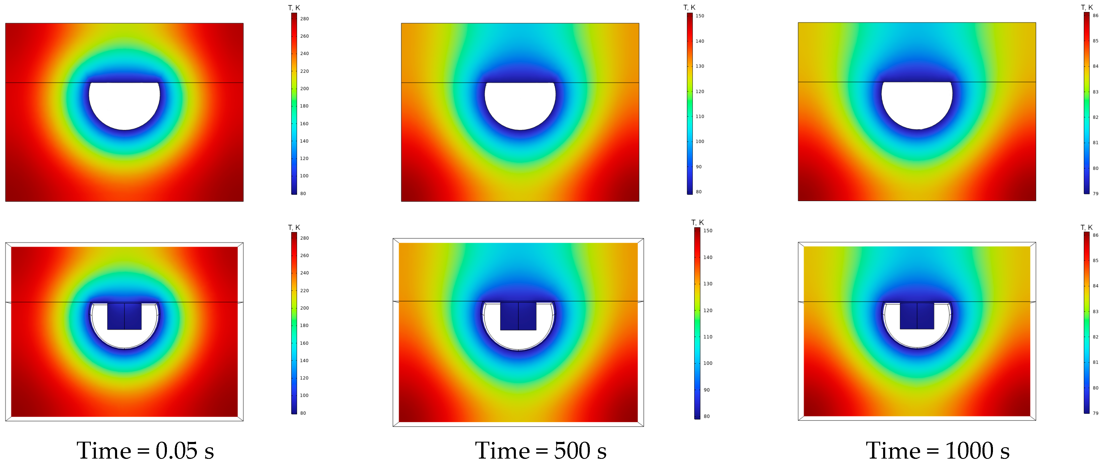
Further in this section, we will consider thermal modeling of the channel profile at the moment of steady-state temperature on the top plate (
Figure 11).
The temperature distribution along the transverse profile of the channel gave approximately similar results. The operating temperature of about 80 K from room temperature was reached after 1000 s. However, despite such results, the presence of a turbulator on the top plate (wedge or pins) has almost no effect on thermal conductivity across the top plate. Therefore, they are more effective for hydrodynamics than for heat exchange.
5. Conclusions
The results of the 40 min experiment indicate that the upper limit of cryotemperatures (lower than 150 K) is reached on the surface of the copper universal cryopanel within 30 min. The minimum achieved temperature was 88 K. The average minimum temperature on the surface was 93 K. Cooled nitrogen (80 K) was used, with a flow rate of 0.05 m/s, flowing through a semicircular channel with a radius of 3 mm and a system of pins with a height of 2.3 mm and a radius of 1.5 mm. It should be noted that the obtained results served as verification and assessment of the adequacy of the computer model. The results of the 40 min experiment indicate that the upper limit of cryotemperatures (lower than 150 K) is reached on the surface of the copper universal cryopanel within 30 min. The minimum achieved temperature was 88 K. The average minimum temperature on the surface was 93 K. Cooled nitrogen (80 K) was used, with a flow rate of 0.05 m/s, flowing through a semicircular channel with a radius of 3 mm and a system of pins with a height of 2.3 mm and a radius of 1.5 mm. It should be noted that the obtained results served as verification and assessment of the adequacy of the computer model. The cryopanel model effectively describes the cooling process at the center of the plate; however, clarifications are needed at the cryopanel’s entrance, and a revision of the model for liquid nitrogen flow is required, as outlined in our research group’s project plans.
Changing the design of the upper plate of the cryopanel will optimize heat transfer by increasing the contact area with nitrogen along the channel. The choice of cylindrical pins on the top plate will not significantly affect the overall laminar flow of liquid nitrogen but will ensure mixing under the top plate. Intensifying mixing in the top wall layer, where nitrogen from the center of the flow is drawn in, will result in a decrease in flow temperature and rupture caused by alternating pins.
The obtained experimental results provide data on the operating mode and temperatures of the developed universal cryopanel. The data also serve as a system for refining and verifying computer models and calculations that will help optimize the design of cryopanels for various tasks requiring temperatures in the range from 300 to 80 K. Such tasks may include sublimation drying and freezing of food products, cooling biological samples for cryoelectron microscopy, and maintaining low temperatures of superconducting compounds. The cryopanels being developed are also better suited for temperature manipulation, allowing control of a given temperature value, as well as additional cooling or heating of a sample on its surface.
Within the framework of the current project, the obtained results justified the design and development of a universal cryopanel. Further research in this area will focus on optimizing the cooling process and enhancing the cryopanel design by eliminating heat losses and leaks. Studying the cryopanel operating modes will allow expanding the range of achievable temperatures (up to liquid nitrogen temperatures). The possibility of assessing the shape, pitch, and offset of the pins is also being considered to improve heat transfer further and evaluate the cooling capacity during the flow of a multiphase stream of current lines, taking into account the boiling of liquid nitrogen.
