Article

Investigation of an Innovative Blade with an Internal Channel and Tangential Slots for Enhanced Thrust Generation Using the Coanda Effect

by
Fanel Dorel Scheaua
1,*,
Almat Mukhamedrahim Ramazanuly
2,* and
Ionut Cristian Scurtu
3
1
Machine Mechanics and Technological Equipments MECMET Research Center, Dunarea de Jos University of Galati, 800008 Galati, Romania
2
Department of Thermal Physics, Karaganda University named after E.A. Buketov, Karagand 100024, Kazakhstan
3
Mirceacel Batran Naval Academy, 900218 Constanta, Romania
*
Authors to whom correspondence should be addressed.
Appl. Sci. 2025, 15(18), 10117; https://doi.org/10.3390/app151810117
Submission received: 16 July 2025 / Revised: 1 September 2025 / Accepted: 5 September 2025 / Published: 16 September 2025

Abstract

Featured Application

This innovative blade design, developed for wind generators, integrates an internal channel and tangential slots to utilize the Coanda effect. The application of this aerodynamic phenomenon significantly improves airflow attachment along the blade surface, resulting in enhanced thrust and reduced drag. This technology can be implemented in modern wind turbines to increase their efficiency and energy output, especially under varying wind conditions. Additionally, the design has potential applications in aerial propulsion systems, where passive flow control is essential for performance optimization.

Abstract

This study presents the design, numerical analysis, and experimental validation of an innovative wind turbine blade incorporating an internal flow channel and tangential slots to harness the Coanda effect for enhanced aerodynamic performance. The primary objective is to improve thrust generation and lift while reducing drag, thereby increasing the efficiency of wind turbines and potential aerial propulsion systems. A three-dimensional blade model was developed in COMPAS-3D and fabricated using PET-G filament through 3D printing, enabling precise realization of the internal geometry. Computational fluid dynamics (CFD) simulations, conducted in ANSYS Fluent using a refined mesh and the k—ω SST turbulence model, revealed that the proposed blade design significantly improves pressure distribution and airflow attachment along the blade surface. Compared to a conventional blade under identical wind conditions (12 m/s), the innovative blade achieved a 12% increase in power coefficient, lift force of 33 N and drag force of 60 N, validating the efficacy of the Coanda-based flow control. Wind tunnel experiments confirmed the numerical predictions, with close agreement in thrust and lift measurements. The blade demonstrated consistent performance across varying wind velocities, highlighting its applicability in renewable energy systems and passive flow control for aerial platforms. The findings establish a practical, scalable approach to aerodynamic optimization using structural enhancements, contributing to the development of next-generation wind energy technologies and efficient propulsion systems.

1. Introduction

Improving aerodynamic performance and energy efficiency is a critical challenge in modern engineering, particularly in the fields of wind energy and aerospace propulsion systems. Flow control technologies applied to blades play a significant role in enhancing the performance of wind turbines and aircraft engines. Among the various aerodynamic mechanisms, the Coanda effect as a phenomenon where a fluid jet attaches itself to a nearby surface—offers promising opportunities for generating additional thrust and improving flow attachment.
The Coanda effect is related on the tendency of air stream to the nearby curved surface of the blade rather than continuing in a straight line, then air flows over a convex surface, it tends to follow the blade contour due to lower pressure created by acceleration of the fluid (Bernoulli principle).
The effect can be exploited to redirect airflow, increase lift, and reduce separation on blades. For vertical-axis turbines (like Darrieus or H-Darrieus types), one of the challenges is that the blades experience wide variations in angle of attack as they rotate and this often causes stall at certain positions, which reduces efficiency.
The Coanda effect is intended to be used to delay the flow separation while the curved blade profiles designed with Coanda-enhancing surfaces (like trailing-edge flaps or leading-edge slots) keep airflow attached for a longer time period while this increases lift and reduces drag across a wider range of angles of attack.
The expectations are related to the lift-to-drag ratio enhancement by controlling airflow adherence, when the turbine extracts more energy from lower wind speeds.
This is especially important for VAWTs, which often underperform compared to horizontal-axis turbines in low-wind conditions.
Passive or active flow control on the special blade geometries (rounded edges, curved trailing surfaces, or “Coanda lips”) is intended to achieve better performance results of the vertical axis turbines (VAWTs).
The active process is injecting small amounts of air through slots on the blade surface to trigger the Coanda effect (similar to blown flaps on aircraft wings improving the self-starting process, because many VAWTs struggle to self-start at low wind speeds.
By improving lift via the Coanda effect, blades can overcome inertia forces more easily.
The design strategies using the Coanda Effect are exploring the blade profile modification by adding curvature to the suction side of the blade to encourage airflow adherence and the expected result is more consistent lift across the rotation cycle.
Also, the trailing edge Coanda surfaces extend so that airflow follows it instead of separating abruptly with the result of stall delay together with a smooth in the power output.
The main air stream augmentation with small air channels on the blade that release air jets tangentially is able to provide better results of maintaining the attachment at high angles of attack but increases system complexity.
Another method is represented by shrouded VAWTs with Coanda guides, where a diffuser or shroud around the rotor uses the Coanda effect to channel more air through the blades, while expecting a higher amplitude of effective wind speed directed to the rotor.
The reported benefits (from research & experiments) of up to 20–30% increase in power coefficient (Cp), declared from the experimental research of VAWTs using Coanda-enhanced blades, with significant reduction in stall losses at high angles of attack, an improved low-wind-speed performance and self-starting capability.
Shires &Kourkoulis (2013) [1], proposed CC blades for H-type VAWTs, while they modeled a rounded trailing edge with a thin tangential jet (classic Coanda setup). Further, using CFD method for section aerodynamics and a DMST rotor model including pumping power reached the principal findings related to lift coefficient that grows linearly with jet momentum coefficient (from 14.1 to 27.8 or their CC section), while net power augmentation is achievable if the blowing is azimuthally modulated, otherwise, pump power can wipe out gains. They stress the design trade-off, with thicker TE for Coanda effect resulting more base drag, so section optimization matters.
Wilhelm et al. (2009–2017) [2,3,4], developed CC-VAWT analytical and controls framework, moved beyond “constant blowing” to dynamic/azimuthally scheduled CC to cut jet power while expanding the power envelope, and the results show the dynamic CC schedules that can reduce required jet momentum vs. constant-blowing cases while raising Cp and widening the TSR operating range for the rotor. Is introduced control mappings of required momentum coefficient vs. azimuth/TSR in order to keep the turbine on its best performing “virtual solidity”.
Larion & Lemu (2014) [5], based on CFD analysis and theory on a patented VAWT concept that adds a small auxiliary “Coanda” blade near the main blade’s edge to deflect flow, create a low-pressure region behind the blade and generate tangential (useful) force.
The key research findings are represented by higher drag in the direction of rotation (thus ensuring more rotor torque) especially when the auxiliary Coanda blade angle was tuned. Some valuable power-comparison plots are presented, that are noting the need for experimental validation of the model.
Also, useful results regarding the design ideas related to circulation/flow-control are presented by Zhang et al. (2020) [6], that studied split flaps on H-VAWT blades, while the findings are related to optimal geometry (~22% chord length, 10° deflection, ~92% chord location), with reported Cpmax +5.8% and efficient TSR range +25.9%, by altering TE boundary conditions and boosting circulation, with good results for low-TSR help without pumps.
Several works (trating suction, synthetic air jets, plasma) show the same principle of control separation and modulate circulation around azimuth to gain Cp. while these are considered as baselines for expected gains and control scheduling.
Practical takeaways from these papers standout main result across studies that azimuthally modulated Coanda blowing (or “dynamic CC”) is key constant air blowing that can achieve more rotor pump power. Regarding the blade section design Coanda needs a rounded trailing edge and thin slot; optimize TE radius and slot height to maximize L/D ratio at low momentum coefficient and minimize base drag. The target low-TSR boost and broadened operating band expects are the biggest benefits at low TSR, plus a wider efficient range mirrored by passive flap studies.
Recent research highlights the potential of applying the Coanda effect through innovative blade designs that integrate internal channels and tangential slots, while such configurations can redirect airflow in a controlled manner, intensifying surface adhesion and enhancing overall aerodynamic efficiency. Such improvements are especially valuable for optimizing wind turbine rotors and aircraft propulsion systems under varying flow conditions [7].
This study investigates a novel blade concept featuring an internal channel and tangential ejection slots designed to exploit the Coanda effect. The primary objective is to evaluate the aerodynamic characteristics and thrust enhancement potential of the proposed blade design through both numerical simulations and theoretical analysis. The methodology includes computational fluid dynamics (CFD) modeling and comparative performance assessments with conventional blade configurations.
The originality of this work lies in its approach to amplify the Coanda effect via internal flow control mechanisms within the blade structure. The findings of this research may contribute to the development of high-efficiency energy systems and advanced aerodynamic technologies applicable in both renewable energy and aerospace industries.

2. Materials and Methods

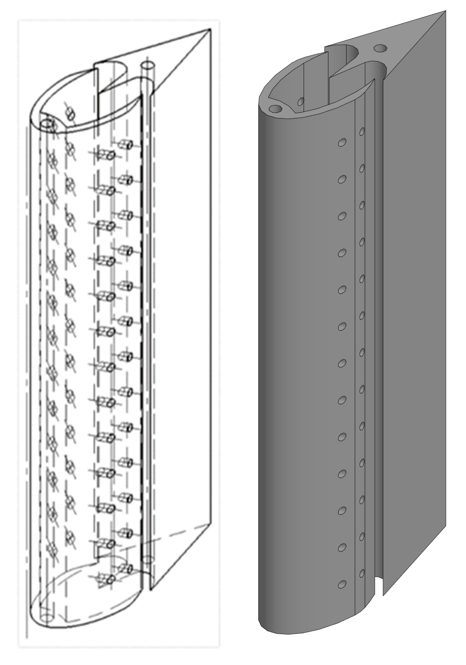
The experimental and simulation-based evaluation of the innovative wind turbine blade, designed to leverage the Coanda effect, provided valuable insights into its aerodynamic and structural performance. The three-dimensional model, constructed at a 1:1 scale using COMPAS-3D and fabricated via 3D printing, was subjected to testing in an aerodynamic wind tunnel to assess its efficiency and load characteristics. Numerical simulations in ANSYS further corroborated the experimental data by analyzing flow behavior, pressure distribution and material stress [8,9,10,11]. The blade’s design, featuring an internal channel and tangential apertures, is detailed below (Figure 1).
The operational principle of the blade is implemented as follows: air enters through the air intake slot, creating a directed rotational flow within the internal space. This process results in the formation of a high-pressure zone in a specific area. The compressed air is expelled at high velocity through the tangential apertures, adhering to the blade surface via the Coanda effect, thereby generating additional propulsive force [12,13,14].
This mechanism not only enhances aerodynamic efficiency but also enables energy savings in wind turbines and propulsion systems. The application of such technologies plays a crucial role in improving the efficiency of renewable energy sources in the future. For mathematical modeling, a three-dimensional model of the blade was developed at a 1:1 scale based on the design. This model was subsequently 3D-printed and utilized for experimental studies in an aerodynamic wind tunnel [9,15]. The model’s representation can be viewed in the following image (Figure 2).
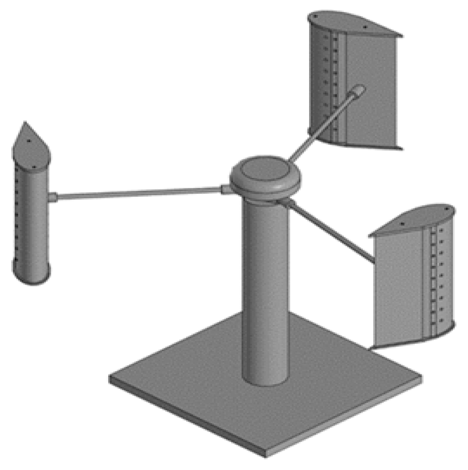
The model, created in COMPAS-3D, is intended solely for mathematical modeling in ANSYS and is not designed for physical prototype construction but rather for calculating the aerodynamic and structural characteristics of the design. The blade features an innovative structure, including an internal channel and tangential apertures. The internal channel facilitates airflow, while the arrangement of tangential apertures ensures additional traction force through the application of the Coanda effect. This solution enhances the efficiency of wind installations and optimizes the energy production process.
The blade’s geometric features require complex mathematical models, necessitating the use of numerical methods in ANSYS for comprehensive analysis. This modeling plans to investigate flow behavior, pressure distribution, and material resistance to loads. The blade’s overall shape was specifically selected to optimize aerodynamic characteristics. The internal channel is integrated into the design, with its length and width engineered according to calculations. The tangential apertures are positioned at specific angles, directing airflow to generate additional traction force [4].
This innovative structure is applied in the development of a new generation of wind generators. Its key advantages include increased aerodynamic efficiency, structural strength, and high energy production levels. Research findings indicate that this design outperforms standard blades. Material selection is also critical, as the internal channel and aperture placement must maintain structural integrity. For blade modeling, high-strength composite materials or aviation-grade aluminum are considered, offering resistance to high loads and enabling long-term use.
This project is aimed at advancing new technologies in wind energy. Following the modeling results, future plans include prototype development and field testing. Research to further improve the blade’s aerodynamic characteristics will continue.
To evaluate the aerodynamic behavior and structural performance of the proposed blade, a detailed computational fluid dynamics (CFD) simulation was carried out using ANSYS Fluent. The following section describes the simulation setup and parameters.

CFD Simulation Setup

For the present study, both steady-state and transient simulation strategies were considered for the vertical-axis wind turbine rotor. Steady-state analysis using the Multiple Reference Frame (MRF) approach offers the advantage of lower computational cost and faster convergence, making it suitable for preliminary design assessments and parametric sweeps across tip-speed ratios. However, this method only predicts time-averaged flow fields and may overestimate performance since it cannot resolve unsteady effects such as dynamic stall or torque ripple. By contrast, transient simulations with a sliding mesh approach are computationally more demanding but essential for accurately capturing the unsteady aerodynamics of VAWTs. This includes resolving blade–wake interactions, dynamic stall and periodic torque fluctuations, which are critical for reliable prediction of power output and structural loading. Consequently, steady-state results are mainly used for initial evaluation, while transient simulations provide the detailed performance characteristics necessary for design validation [12,13,14].
To investigate the aerodynamic performance of the proposed wind turbine blade design, detailed computational fluid dynamics (CFD) simulations were performed using ANSYS Fluent. The objective was to evaluate the influence of the internal flow channel and tangential slots engineered to exploit the Coanda effect on the pressure distribution, flow attachment and overall aerodynamic efficiency of the blade.A three-dimensional computational domain was constructed around the blade geometry to ensure accurate representation of external flow behavior. The blade model, developed in COMPAS-3D, was imported into ANSYS and discretized using a refined hybrid mesh, consisting of tetrahedral and hexahedral elements. Special attention was given to mesh refinement in the near-wall regions using inflation layers, enabling precise resolution of boundary layer characteristics and shear stresses. A grid independence study was conducted to ensure that the simulation results were not sensitive to further mesh refinement.
The simulations employed the k—ω Shear Stress Transport (SST) turbulence model, selected for its proven capability in handling flow with adverse pressure gradients and separating boundary layers—conditions expected in regions influenced by the Coanda flow control mechanism. Predominantly steady-state simulations were conducted; however, selected transient analyses were also performed to capture unsteady flow phenomena and validate the persistence of attached flow under varying conditions.
Boundary conditions included a uniform inlet wind velocity of 12 m/s, with atmospheric pressure specified at the outlet. The blade was treated as a stationary wall with a no-slip condition applied and symmetry conditions were imposed where appropriate to reduce computational cost.
Results from the CFD simulations demonstrated that the integration of the internal channel and tangential slots led to a significant improvement in flow attachment along the blade’s suction surface.
The computational domain was created around the blade to analyze the airflow behavior using ANSYS Fluent. The domain was configured with the following boundary conditions [7,8,11]:
Inlet: Velocity inlet, uniform wind speed (v = 12 m/s);
Outlet: Pressure outlet, set to 0 Pa gauge pressure;
Air density ρ , with dynamic viscosity μ ;
Air mass flow rate: Q m ;
Rotor geometry: radius R, height H, chord c, number of blades Nb;
Tip speed ratio (TSR):
λ = ω R v
Reynolds number (sectional):
Re = ρ v c μ
Swept area:
A = 2 R H
Coefficient of torque and power:
C T = T 1 2 ρ A R v 2 ; C P = P 1 2 ρ A v 3
Rotor turbine generated torque:
T = 1 2 ρ A R C T v 2
Turbine power:
P = T · ω = 1 2 ρ A C P v 3
Momentum coefficient (for Coanda Effect):
C μ = T 1 4 ρ A v 2
Blade surface: No-slip wall condition.
Side walls: Symmetry boundary conditions.
The governing equations regarding low Mach conditions, pressure-based solver in Ansys Fluent are represented by the continuity (conservation of mass) and momentum (conservation of momentum) equations within the inertial frame:
· u = 0 ρ u · u = p + · μ + μ t u + u T
The Equation (8) represents the Navier–Stokes equation for an incompressible fluid, where μ t appears as turbulent viscosity (RANS modeling).
For the rotating reference frame for steady state of sub-components of the rotor model:
ρ u r · u r = p + · μ + μ t S 2 ρ · Ω × u r ρ · Ω × Ω × r
The second form Equation (9) appears when the system is considered in a rotating frame such as the case of a turbine rotor.
The momentum equation, written in a rotating reference frame with Coriolis and centrifugal terms 2 ρ Ω × u r ; ρ Ω × Ω × r where u , u r velocity and velocity of the rotating frame, Ω = ω z . Both Equations (8) and (9) equations are the mediated Navier–Stokes (RANS) equations for an incompressible fluid, with and without rotational terms.
The turbulence model used was k—ω SST (for separation and adverse pressure gradients), selected for its high accuracy in predicting boundary layer behavior and flow separation along curved surfaces, which is critical in analyzing the Coanda effect. To close the system, since (μt) is the unknown turbulent viscosity, a turbulence model is needed.
The equation for k the turbulent energy an equation for ω the specific dissipation frequency forms the RANS model k—ω which gives μt.
The transport equation for turbulent kinetic energy (k) within the k–ω model is:
ρ k t + · ρ k u = P k β ρ k ω + · μ + σ k μ t k
ρ ω t + · ρ ω u = α ω k P k β ρ ω 2 + · μ + σ ω μ t ω + 2 1 F 1 ρ σ ω 2 1 ω k · ω
where are used the eddy viscosity μ t , and special blending functions used by Ansys Fluent internally (F1).The transient sliding mesh is recommended for rotor-stator interaction and correct unsteady aerodynamics since rotor cell zone rotates with ω and interfaces are sliding.
The continuity equation + momentum (Navier–Stokes) describe the motion of the fluid.
The Equation (10) is part of the turbulence closure model (k—ω) which provides the turbulent viscosity used in the Equations (8) and (9).
The boundary conditions consider the inlet with velocity values, turbulence intensity, turbulent viscosity ratio or length scale, while for the outlet the pressure outlet values are stated to 0 Pa gauge.
At wall regions represented by blades, no-slip conditions are declared, with sliding mesh interfaces (rotor-stator), coupled with conservative interpolation.
The pressure based transient solver, with absolute velocity formulation, incompressible flow, with second-order discretization schemes, is enhancing the pressure–velocity coupling stated as coupled for faster convergence at strong rotation.
For spatial discretization momentum, k , ω the second order upwind is selected or bounded central for momentum if stable, while pressure is set to second order.
The air was modeled as an ideal gas at 25 °C, with a density of 1.184 kg/m3 and dynamic viscosity of 1.849 × 10⁻⁵ Pa·s.
The time step Δ t that is dictated by blade rotation resolution, the proper range is set to Δ θ = 0.5 o 2 o per each step:
Δ t = Δ θ ω
The convergence per step which scales residuals for continuity/momentum/turbulence, with option to monitor torque and air stream mass flow rate, which require periodic repeatability over 3 to 5 rotor blade revolutions.
The post-processing for forces, power and coefficients involves calculating and outputting these values from raw simulation data. This process typically uses dedicated function objects or tools within simulation software (Ansys Fluent V14.5) to integrate forces and moments over selected blade surfaces, convert them into dimensionless coefficients and often visualize the values graphically for analysis. The key coefficients include power, drag (Cd), lift (Cl) and moment (Cm), which are essential for vertical axis rotor wind turbine (VAWT) performance analysis and comparing simulation results to experimental data or theoretical predictions.
The main parameters related are represented by surface traction on the blade:
t = p · n + τ · n
The turbine rotor torque about vertical axis (z) is expected according with the relation:
T z = S b r × t · z d S
The power coefficient for VAWT swept area (A = 2RH) and extracted power is described by the following relations:
P = T z · ω ; C P = P 1 2 ρ v 3 A
while the lift and drag coefficients on blade section:
C L = L 1 2 ρ v r e l 2 A ; C D = D 1 2 ρ v r e l 2 A
With local relative velocity values from inflow and rotational components.
To ensure the accuracy and reliability of the CFD simulations, a systematic validation procedure was carried out.
In terms of a grid independence study, the computational mesh was refined progressively in the near-wall region and in the wake to verify solution sensitivity. The key output parameters, namely the rotor torque, power coefficient and surface pressure distributions, were monitored, while the final grid was selected when further refinement produced negligible changes in these quantities.
For time-step independence the temporal resolution was verified by halving the time step Δt. The mean torque values obtained with the refined time step were compared to the baseline, and independence was confirmed when the variation was within 1–2%.
Regarding turbulence model sensitivity the influence of turbulence modeling was assessed by comparing results from the baseline SST k—ω model against the transitional SST model (for Reynolds numbers Re ≤ 2 × 10e5) and the Spalart–Allmaras model. Consistency of torque and pressure fields across models was used as the criterion for robustness.
Finally, the periodicity of the unsteady solution was evaluated by comparing the azimuth torque histories over consecutive rotor revolutions. Convergence was established when torque traces overlapped, indicating that a periodic steady state had been reached [16,17,18,19].

3. Results

This section presents a detailed visual investigation of the blade’s aerodynamic characteristics, focusing on the structure of the airflow and the distribution of pressure. The efficiency of the innovative design is determined through results obtained using the ANSYS Fluent software. The wind turbine blade generates additional traction force due to the presence of its internal channel and tangential apertures, a phenomenon explained by the Coanda effect, wherein the airflow adheres to and flows along a curved surface. This process was meticulously modeled using ANSYS, with results presented graphically for further analysis [11].

3.1. Visualization and Analysis of Results

To study the structure of the wind flow, vector diagrams were generated, elucidating the direction and variations in flow velocity. These diagrams enable the identification of interactions between the flow and the blade surface, as well as the delineation of turbulent regions.
The flow process, illustrated in Figure 3, emphasizes the velocity field illustrated by the unsteady wake development behind the VAWT rotor. As the incoming flow impinges on the blades, a significant deceleration is observed in the downstream region, marked by the blue–green contours, which correspond to reduced velocity magnitudes (<2 m/s) compared to the free-stream inflow. This low-speed region indicates energy extraction from the wind and corresponds to the primary momentum deficit in the wake.
The fluid zones flanking the rotor represent high-shear layers, where the fast-moving free stream interacts with the slowed wake core. These shear layers are associated with strong velocity gradients and are typical sites of vortex shedding and turbulent mixing.
The wake expands laterally as it circulates downstream, which demonstrates momentum diffusion and entrainment of higher-momentum fluid from the surroundings back into the wake.
Within the near-wake region, the velocity vectors show significant recirculation zones, suggesting the presence of dynamic stall vortices and blade–wake interactions that are characteristic of VAWTs., while these unsteady structures are responsible for torque fluctuations that can affect both aerodynamic efficiency and structural loading.
Overall, the results demonstrate the fundamental flow process of a VAWT, where incoming wind velocity is slowed by energy extraction at the rotor level, where a momentum deficit wake is formed and shear-layer vortices enhance mixing and wake recovery further downstream.
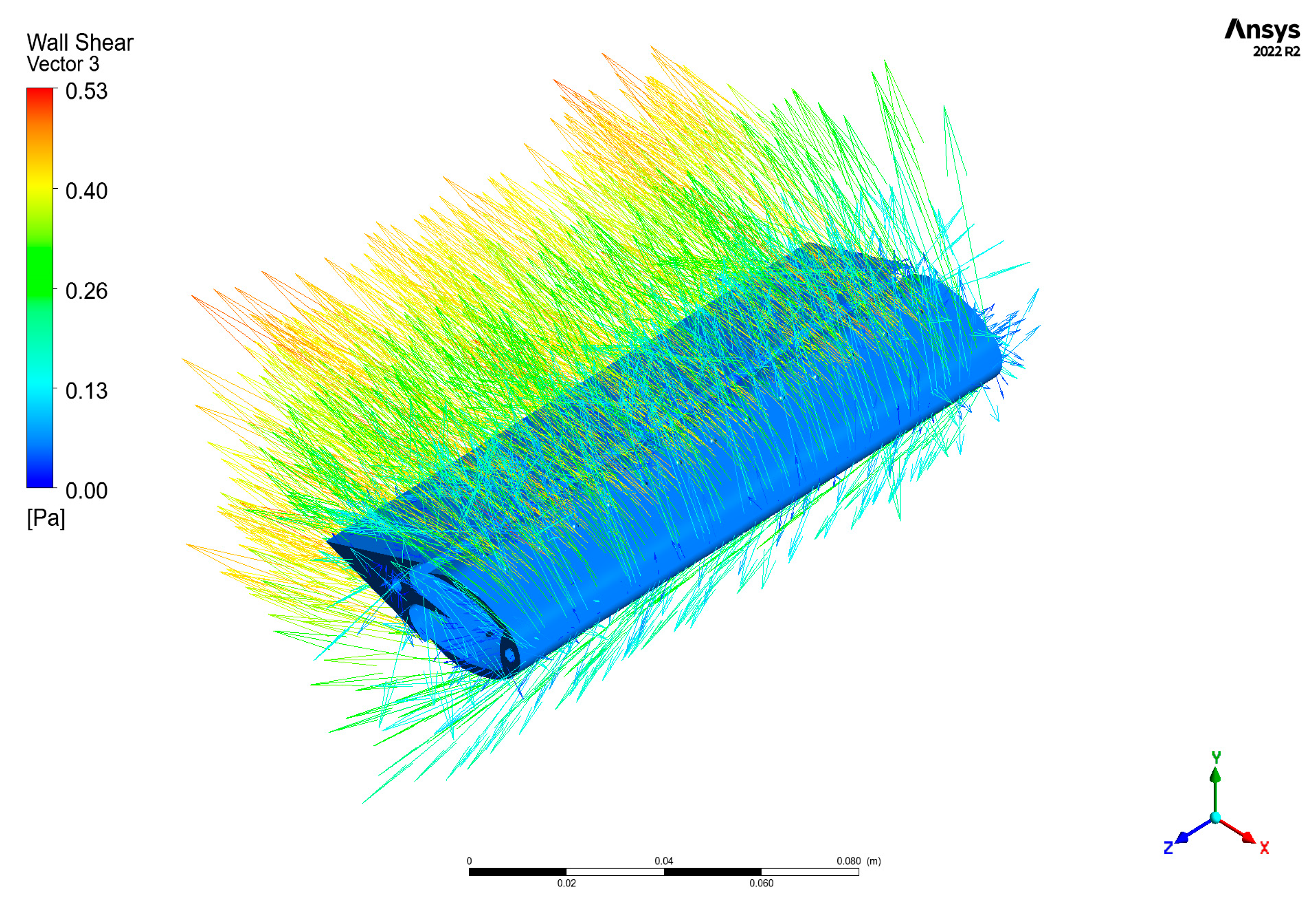
Figure 4 illustrates the distribution of wall shear stress on the blade surface of the VAWT, with contours representing the shear magnitude and vectors indicating the flow direction relative to the surface. The highest wall shear values (red–yellow regions, up to ~0.53 Pa) are concentrated along the leading edge and suction side of the blade. This is consistent with intense pressure gradients and accelerated flow due to blade curvature and local angle of attack.
The trailing edge and pressure side exhibit lower wall shear stress levels, indicating regions of slower boundary layer development and possible separation onset. The flow vectors also reveal attachment along most of the suction surface but with divergence near the trailing edge, which suggests the initiation of separation vortices, while this distribution is significant for evaluating both aerodynamic efficiency and structural performance.
Areas of high wall shear correspond to zones of strong viscous drag and potential surface erosion, while low shear separated regions contribute to unsteady loading and loss of lift. These patterns are crucial for optimizing blade geometry and surface treatment to enhance turbine performance.
A detailed analysis of the flow motion revealed variations in velocity and the presence of turbulent zones. The visualization results demonstrated that the blade’s unique design effectively directs the airflow, thereby enhancing overall aerodynamic efficiency.
The study of pressure distribution, based on computational results, identified differences in pressure across various regions. Elevated pressure was observed in certain areas of the blade surface, while lower pressure was noted in others, contributing to the generation of aerodynamic forces.
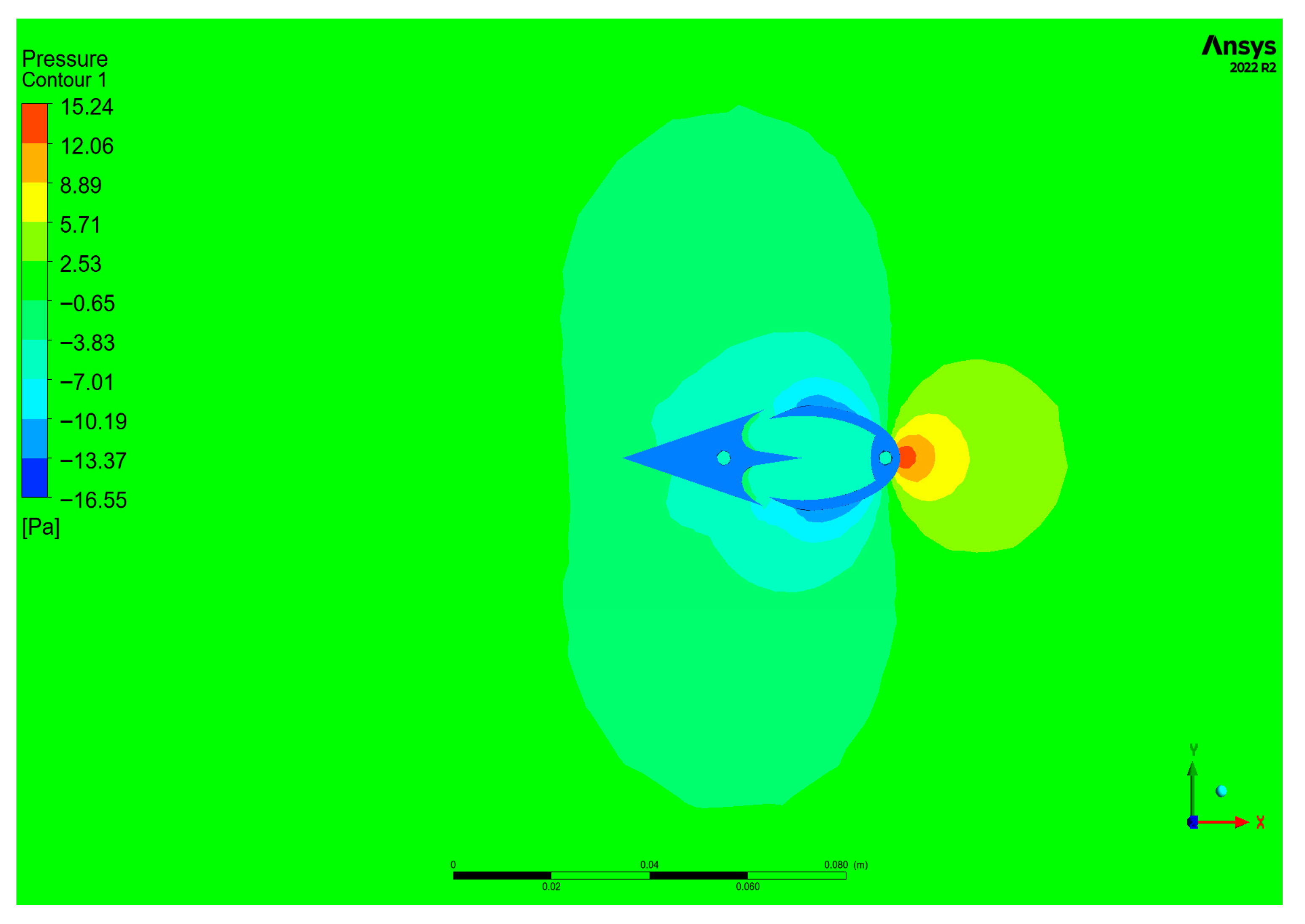
The pressure contour (Figure 5) highlights the fundamental pressure-driven mechanism of energy extraction in the turbine: a favorable pressure gradient across the blade produces lift and torque, while the asymmetric distribution also indicates the onset of unsteady phenomena such as dynamic stall when operated at low tip-speed ratios. The plot illustrates the aerodynamic loading around the blade during operation. A distinct high-pressure region (up to ~15 Pa) is visible on the pressure side near the leading edge, corresponding to the stagnation point where the incoming flow impinges directly on the blade. In contrast, the suction side is dominated by negative pressure values (reaching down to ~−16 Pa), indicating accelerated flow and the generation of lift.
The pressure difference between the suction and pressure surfaces is the main drive of aerodynamic torque on the rotor, while the strong suction peak near the leading edge suggests the presence of flow acceleration and possible leading-edge vortex formation, which are typical in VAWTs under varying angles of attack. Downstream of the trailing edge, the pressure field recovers gradually, with nearly uniform contours indicating wake expansion and momentum deficit.
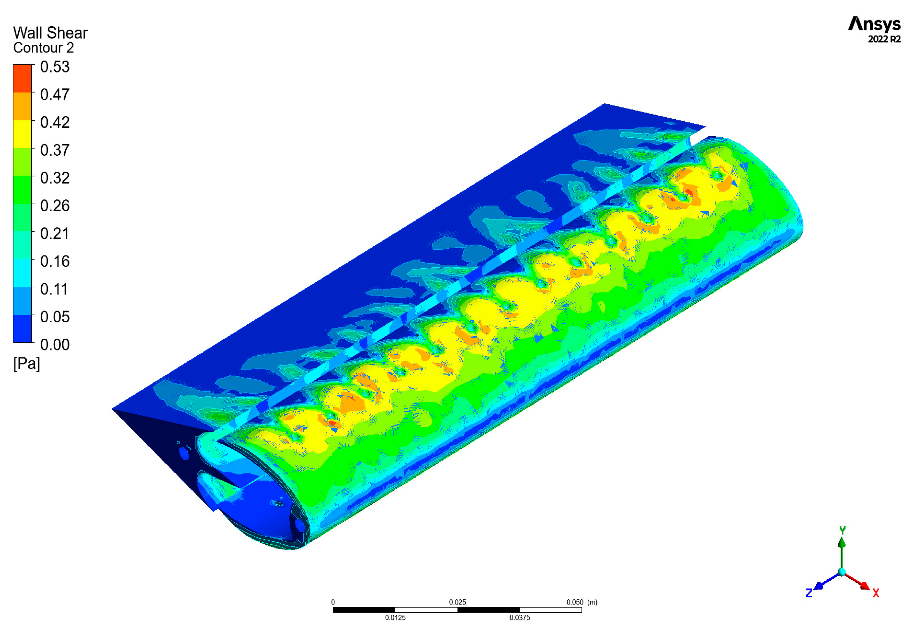
The pressure distribution results across a blade surface (Figure 6) as a critical aspect of aerodynamic performance, is influenced by several factors, including the blade shape, the angle of attack and the flow conditions.
Pressure gradient of air over the blade experiences changes in pressure due to the blade’s geometry. The pressure is lower on the upper surface (suction side) and higher on the lower surface (pressure side). This pressure differential generates lift or thrust, critical for the blade’s function. The flow behavior is characterized by the fluid interactions with the blade surface, in regions where the flow is accelerated, such as near the leading edge and along the upper surface, where lower pressure zones form and this can lead to the development of vortices and other complex flow patterns, especially at higher angles of attack.
The Coanda effect describes the tendency of air stream to stay attached to a nearby surface and this phenomenon can significantly influence the pressure distribution across the rotor blade. If the flow remains attached to the blade surface, it helps maintain a more favorable pressure gradient, reducing the flow separation and this effect enhance lift and improve overall aerodynamic efficiency.
Regarding the pressure distribution analysis based on fluid dynamics (CFD) simulations to analyze these pressure distributions and gradients on different blade designs and flow conditions, the performance optimization and mitigation issues like stall or excessive drag are ensured.
Understanding the pressure distribution process and its relationship with flow behavior and the Coanda effect is essential for optimizing blade design in VAWTs applications, ensuring improved performance and efficiency.
Analysis of pressure differences indicated that the presence of the internal channel and tangential apertures influences the redistribution of airflow. This effect enhances the efficiency of the wind turbine and improves the quality of energy production.
The numerical results clearly evidence the Coanda effect through the attachment of the jet to the curved surface. The wall shear stress distribution exhibits a continuous high region following the surface contour, while surface streamlines seeded at the jet exit remain aligned with the wall, confirming sustained flow adherence. The attachment is further corroborated by the formation of a low-pressure band along the jet trajectory, consistent with the characteristic entrainment and deflection mechanisms of the Coanda effect.
The conducted studies confirmed the accuracy of the modeling results obtained through ANSYS. The data derived from visualization plays a pivotal role in aerodynamic analyses. By refining the blade’s innovative design as presented in Table 1, researchers can enhance the efficiency of wind turbines and optimize energy production metrics.

3.2. Design Evaluation and Simulation Sensitivity

In order to identify a proper way to investigate the innovative blade with an internal channel and tangential slots, we will consider two factors that are affecting the simulation in a 3D computational domain: the mesh sensitivity and the solution stability. To assess the mesh influence in the current simulation, three different cases are considered: the initial mesh, the rougher mesh and the refined mesh. For each case, the mesh metrics are presented in Table 1. The variation of maximum element length in the area of interest is in the range of 0.04 m, 0.02 m and 0.01 m.
Based on the provided mesh metrics and the context of investigating the innovative blade design with an internal channel and tangential slots, the findings regarding mesh sensitivity and its influence on the simulation are related to mesh sensitivity, while the variation in maximum element length in the area of interest suggests a clear approach to assessing how mesh refinement impacts simulation results.
By comparing the initial, rougher and refined meshes, it can be evaluated the accuracy and reliability of the simulation outputs.
The initial mesh has a maximum element length of 0.1 m throughout the domain, but it features a much finer resolution in the area of interest (0.01 m). This fine resolution provides a balance between computational efficiency and accuracy, as it captures critical flow features around the blade and the internal channel effectively.
The rougher mesh, while having a larger maximum element length in the interest area (0.02 m), leads to a significant reduction in the number of nodes and elements. This reduction potentially results in less accurate simulations, especially if critical flow phenomena near the blade edges or slots are not adequately resolved.
The refined mesh increases the maximum element length in the area of interest to 0.04 m. While it still has a finer resolution compared to the rougher mesh, the overall number of nodes and elements decreases significantly, which could lead to a loss of detail in the flow characteristics. Depending on the complexity of the flow, this mesh might not capture essential features effectively.
It’s evident that there is a discrepancy between computational efficiency and accuracy. The initial mesh appears to strike a good balance, providing a detailed representation of the flow field while maintaining a manageable number of nodes and elements. The rougher and refined meshes may compromise accuracy, which is critical for understanding the performance characteristics of the blade design. The choice of mesh also influences the stability of the solution. A coarse mesh led to numerical instabilities, while an excessive refined mesh increases computational time without significant accuracy gains. It is crucial to ensure that the chosen mesh provides stable and convergent solutions across all cases.
The CFD study was achieved with a series of simulations using varying mesh densities in order to identify the point at which increasing refinement yields diminishing returned in accuracy.
Comparing simulation results with experimental data results represents the next step for high-fidelity models in order to validate the findings from the chosen mesh.
Using adaptive meshing option techniques that refine the mesh in areas of high gradient or interest dynamically are expected to optimize both accuracy and computational resources. The proper considerations of mesh sensitivity and solution stability lead to more reliable simulations and better insights into the performance of the innovative turbine rotor blade design.
In conclusion, the visualization results obtained via ANSYS substantiate the efficacy of the proposed innovative design. Improving the aerodynamic properties of the blade surface offers a pathway to increase the operational performance of wind turbines.
These investigations represent a significant step forward in the development of wind energy technology applied to the special design rotor blades of vertical axis wind turbine rotors (VAWTs) which are using the Coanda effect in operation in order to improve the overall performances [13,20,21,22,23,24].

3.3. Development of the Laboratory Model

Following the validation of the innovative blade’s efficiency through mathematical modeling, the creation of a physical prototype and subsequent experimental testing became imperative. To achieve this, 3D printing technology was employed due to its capability to accurately and rapidly produce complex geometric shapes. The blade prototype was fabricated using a 3D printer with PETG polymeric filament, a material distinguished by its high strength, flexibility, and thermal stability, making it suitable for printing aerodynamic components. PETG’s resistance to mechanical loads and ultraviolet radiation further enhances its applicability in wind energy applications.
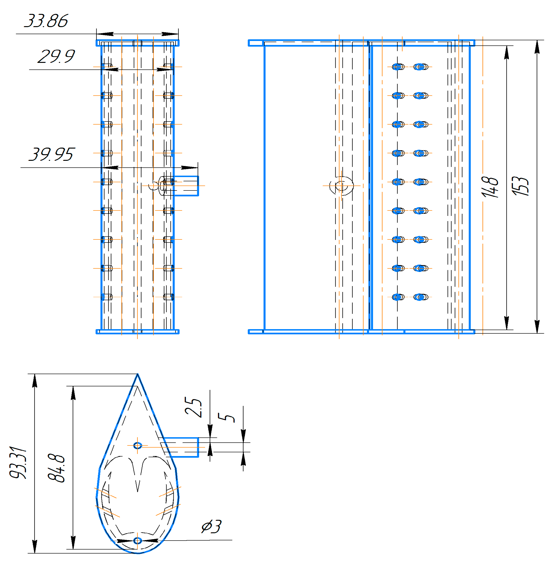
Before initiating the 3D printing process, a detailed technical drawing of the blade was developed to precisely define its geometric dimensions and structural features (Figure 7). This schematic served as a foundational reference for the creation of the experimental model intended for aerodynamic evaluation. The blade’s design incorporates complex internal channels and perforations, which are critical for studying airflow distribution and pressure characteristics in wind tunnel experiments. The dimensions presented in the drawing ensure compatibility with laboratory test rigs and enable accurate reproduction of the blade’s geometry using additive manufacturing techniques [9].
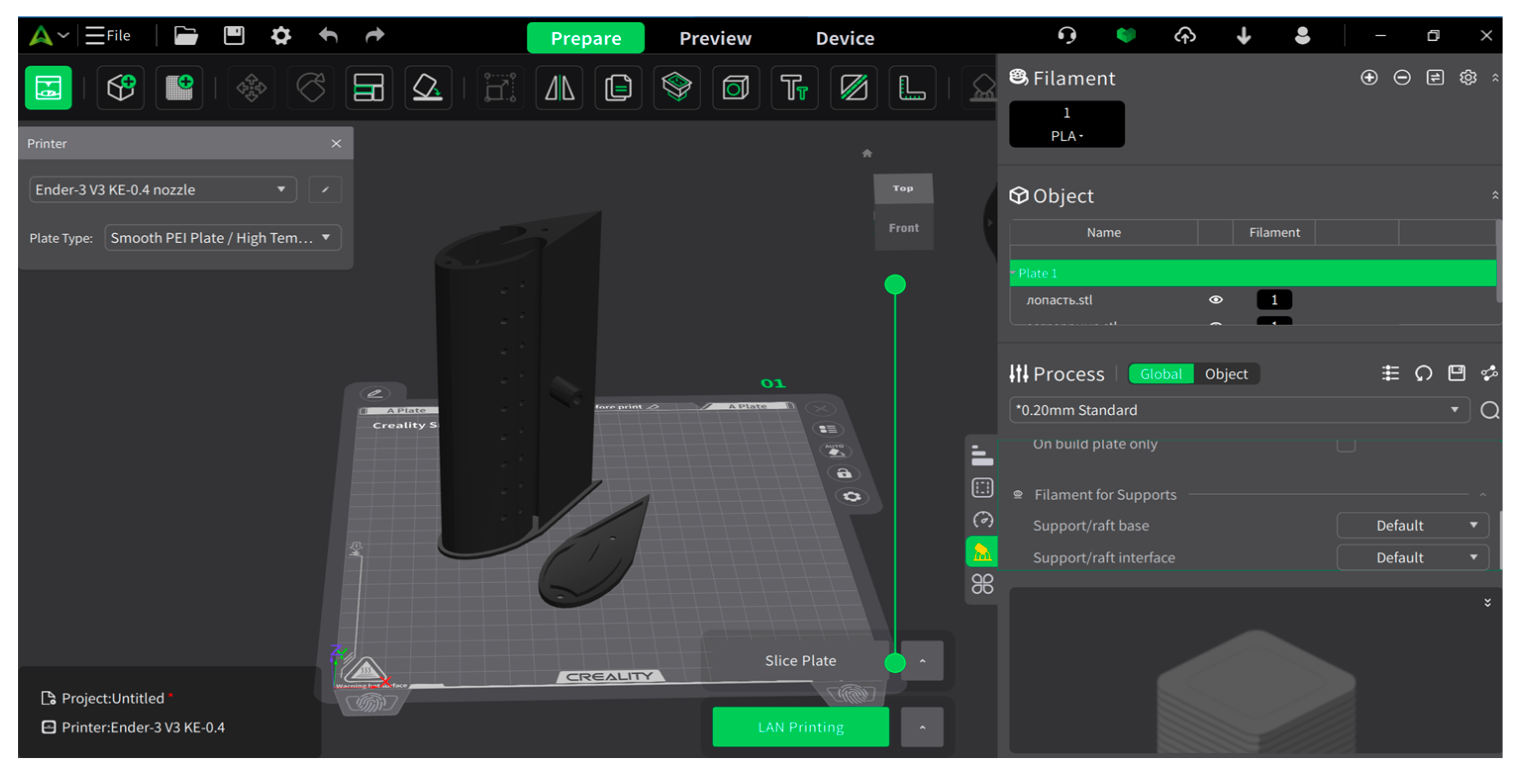
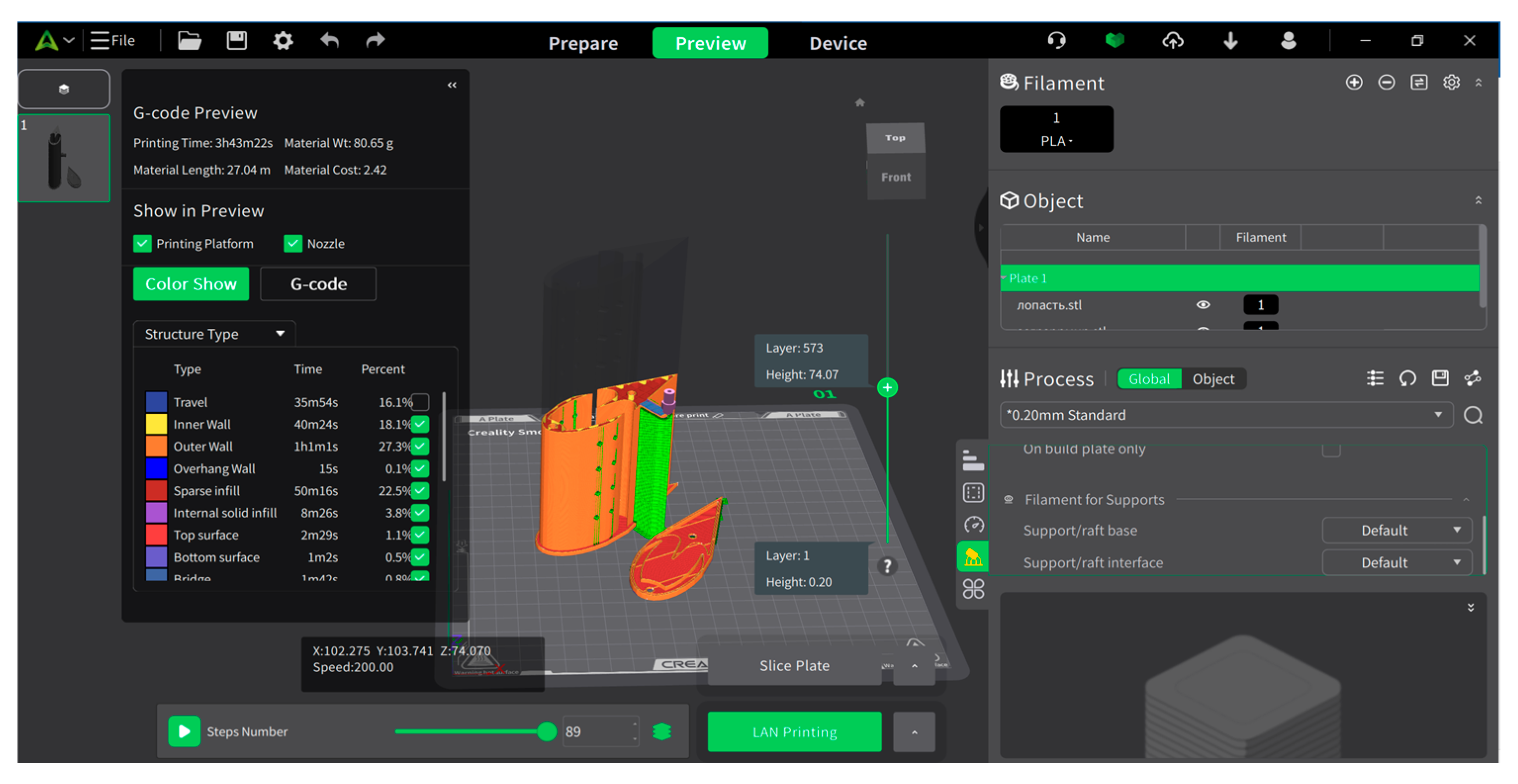
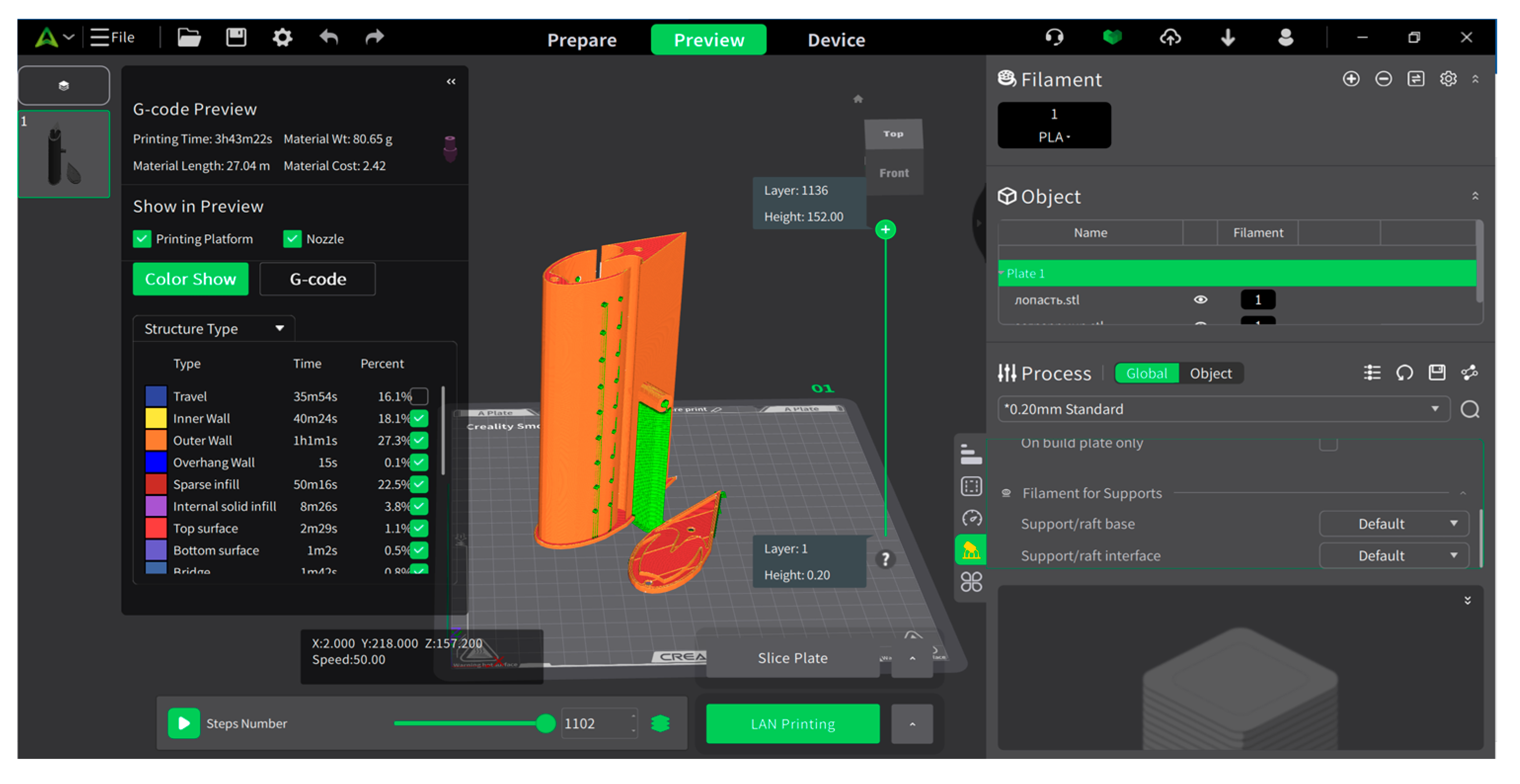
The preparation process for the prototype was conducted using the “Creality Print V5.1.6” software, which facilitates the configuration of the 3D model according to required parameters, adjustment of layer alignment, and optimization of the printing process (Figure 8, Figure 9 and Figure 10).
The printing process comprises several stages. Initially, the 3D model is uploaded in STL format to the “Creality Print” software. Subsequently, key parameters such as layer height, infill density, printing speed, and temperature are specified. For PETG material, the optimal printing temperature ranges from 230–250 °C, with the bed heating temperature set between 80–90 °C.
To enhance the blade’s strength and improve its aerodynamic properties, an infill density of 40–50% was selected, ensuring the accurate representation of internal channels and tangential apertures.
Upon completion of printing, the prototype undergoes mechanical finishing. Where necessary, the surface is smoothed, and excess edges are removed. The finished blade is then prepared for aerodynamic testing. Post-fabrication, the prototype is subjected to evaluation in a wind aerodynamic laboratory, utilizing wind tunnels or specialized test rigs to assess its performance under real conditions. During these experiments, the distribution of airflow, turbulence levels, and pressure variations are meticulously examined [14,21,22,25].
The results of these investigations are utilized to refine the blade’s aerodynamic characteristics and enhance its design. This work contributes to improving the efficiency of wind generators and facilitates the integration of novel technological solutions.
In conclusion, the prototype developed through 3D printing enables the validation of mathematical modeling outcomes, facilitates real-world testing of the design, and provides a basis for its further improvement. The processes of prototype fabrication and experimental testing represent a critical phase in the advancement of innovative technologies within the wind energy sector.

3.4. Characteristics of the Laboratory Model and 3D Design

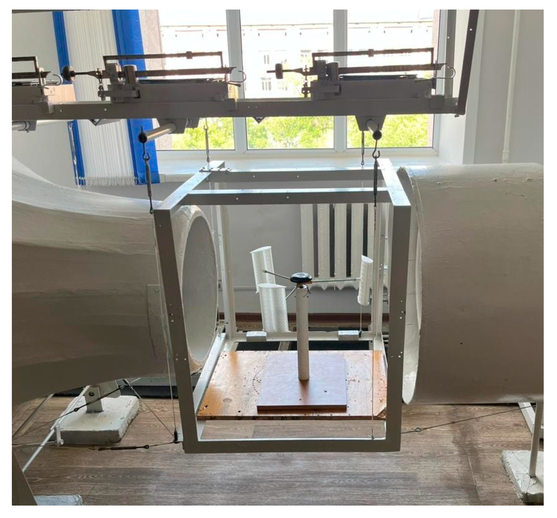
Following the fabrication of the blade prototype, the laboratory model was installed in the test section of a subsonic wind tunnel for experimental validation (Figure 11 and Figure 12). These tests aimed to assess the real-world aerodynamic performance of the blade design, which had previously been analyzed using ANSYS simulations and manufactured via 3D printing.
The wind tunnel is capable of producing airflow velocities ranging from 2.5 to 30 m/s. For this study, the prototype was tested at five discrete velocities of 4, 6, 8, 10, and 12 m/s —to evaluate its performance under varying wind conditions. Particular emphasis was placed on the 12 m/s case, which served as a reference point for comparing alternative blade geometries in subsequent experiments.
The blade retained the main geometric parameters defined during the modeling phase:
Diameter: 440 mm—critical for determining the swept area and interaction with incoming airflow.
Length: 150 mm—providing a balance between mechanical stability and aerodynamic shaping.
Tangential aperture diameter: 4 mm, set at an angle of 30°—optimized to enhance the Coanda effect and guide the internal airflow.
The test section of the tunnel, with a diameter of 500 mm, allowed for central placement of the model while minimizing wall interference. Aerodynamic forces were measured using three high-precision balances mounted above the test area, enabling direct acquisition of lift, drag, and moment values.
This physical testing setup provided experimental validation of the numerical predictions and established a reliable basis for evaluating the aerodynamic efficiency of different blade configurations under identical conditions—particularly at the reference velocity of 12 m/s, where the most pronounced performance differences were observed.

3.5. Experimental Results and TheirAnalysis

The experimental investigations yielded significant data regarding the aerodynamic characteristics of the innovative blade. The obtained results were visualized through graphs, which illustrate the blade’s efficiency and its dependence on wind velocity. The placement of these graphs will be determined by the authors, while the following sections provide their scientific description and significance.
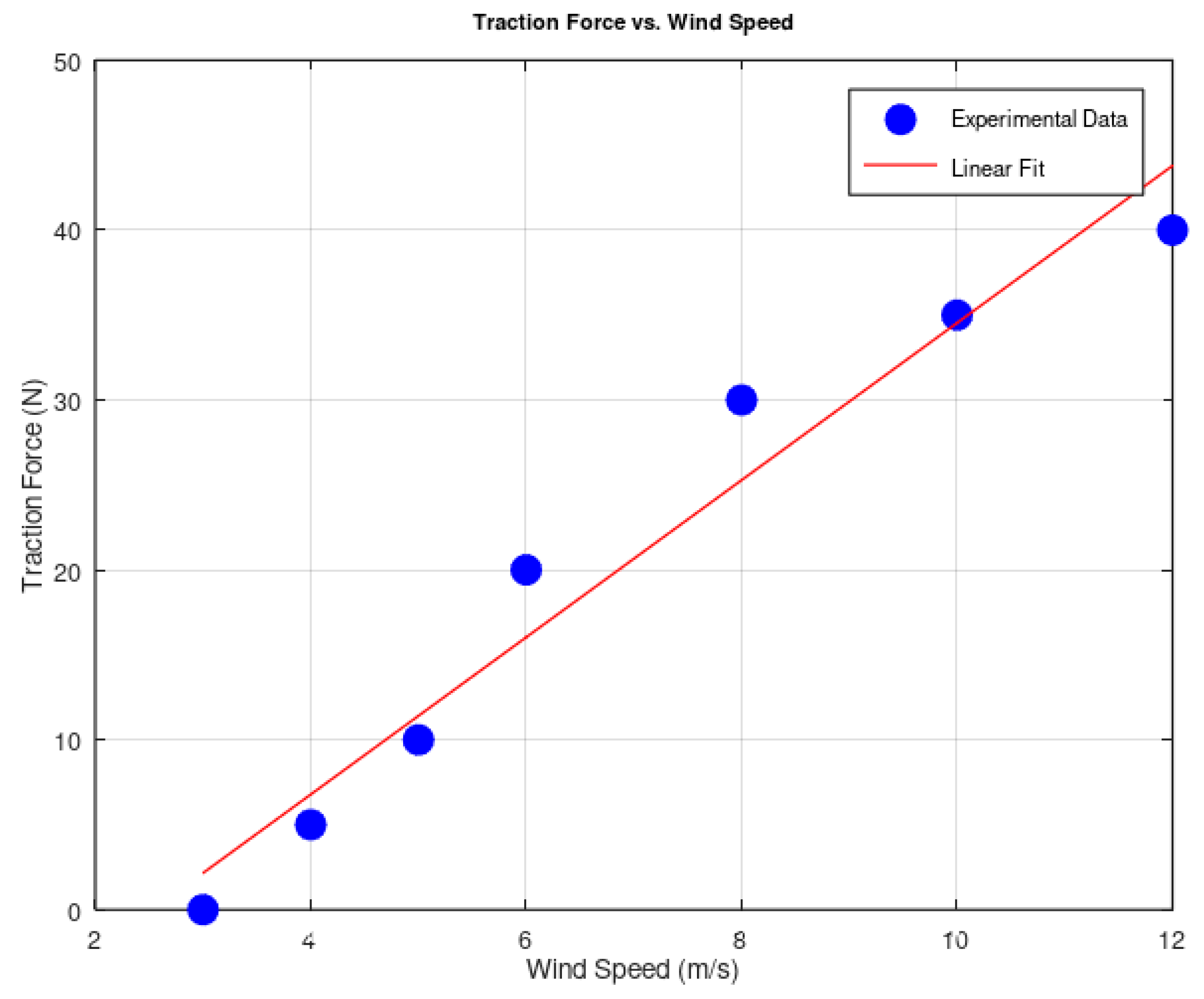
The blade’s traction force increases with rising wind velocity, consistent with the fundamental laws of fluid dynamics. The subsequent graph presents the traction force values across various wind speeds (Figure 13).
The graph indicates that the traction force is approximately 0 N at a wind speed of 3 m/s, escalating to 40 N at 12 m/s. This outcome underscores the role of the Coanda effect in enhancing traction force through efficient airflow management. The traction force was measured using a specialized dynamometer.
To ensure the accuracy and reliability of the experimental data, an uncertainty analysis was conducted. The dynamometer used for measuring thrust and lift forces had a precision of ±0.05 N. The relative error for each measurement was calculated as:
δ = F F × 100 %
where F is the measured force. For example, at a lift force of 33 N, the relative error is approximately:
δ = 0.05 330 × 100 % 0.015 %
This minimal error confirms that the measured forces are reliable and suitable for further aerodynamic analysis.
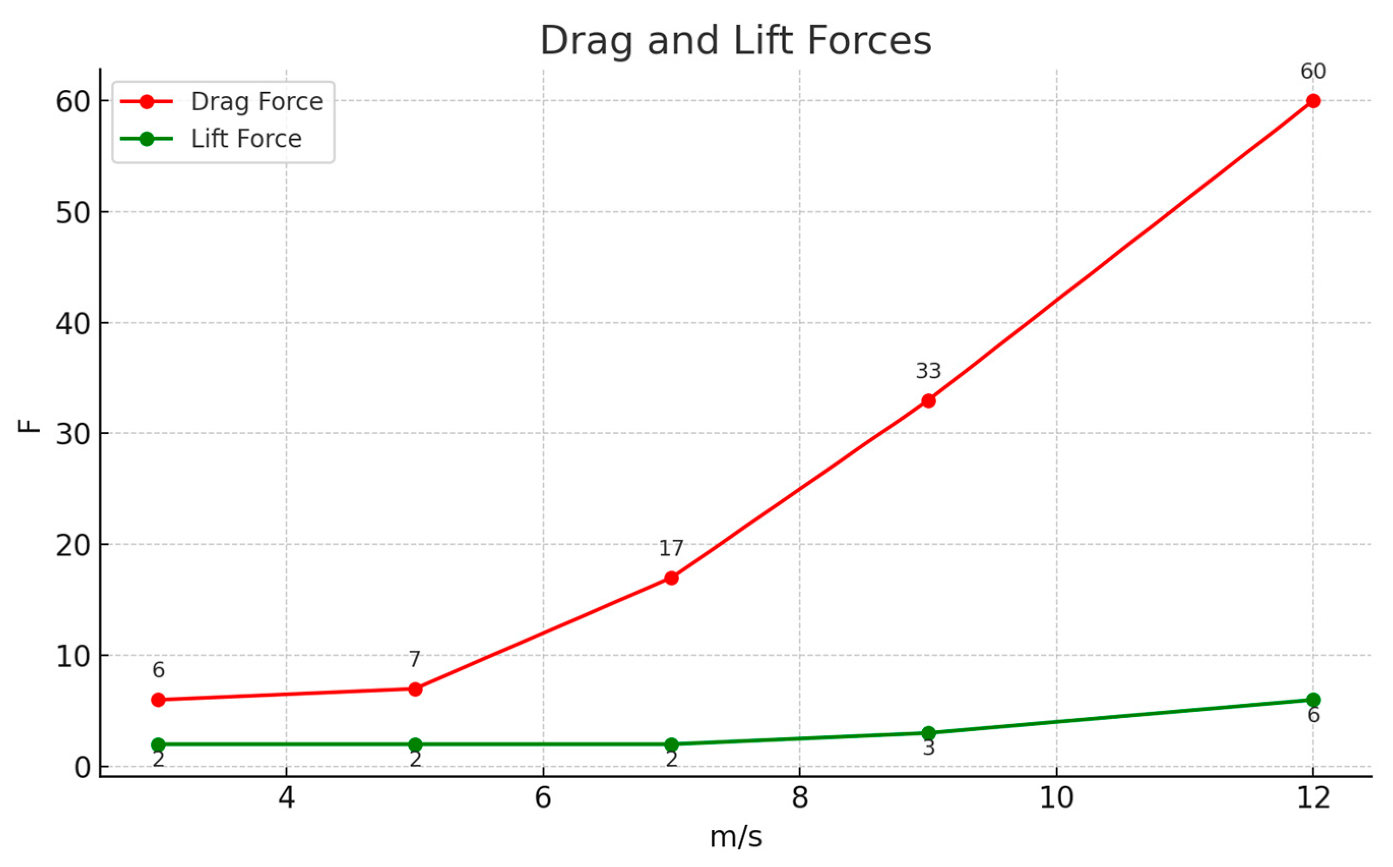
The blade’s frontal drag force and lift force vary with increasing wind velocity (Figure 14). Experimental data revealed a gradual increase in frontal drag force, accompanied by a pronounced rise in lift force.
Graphical results demonstrate a significant increase in frontal drag force with wind velocity. Specifically, at a wind speed of 3 m/s, the frontal drag force is F_d = 6 N, rising to F_d = 60 N at 12 m/s. This tenfold increase highlights the direct correlation with the blade’s aerodynamic properties, particularly its shape and the structure of the internal channel. Similarly, the lift force exhibits a substantial increase with wind velocity: F_l = 2 N at 3 m/s, reaching F_l = 6 N at 12 m/s. These findings indicate the effectiveness of the blade profile and its aerodynamically optimized design [9,15].
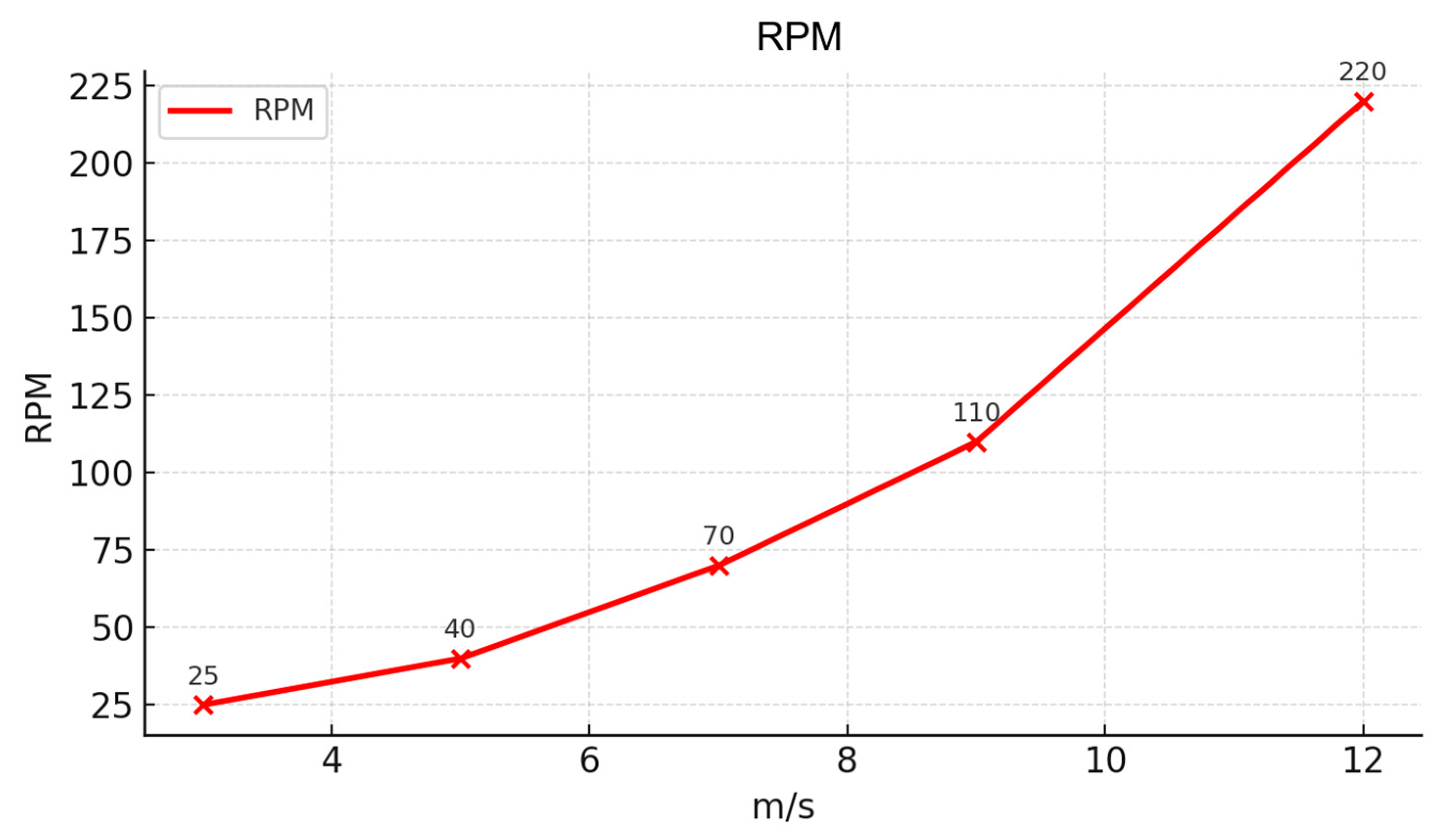
The rotational frequency of the wind turbine, a key dynamic parameter, was also assessed (Figure 15). The experimental findings revealed a linear correlation between wind velocity and rotational frequency, thereby substantiating both the kinematic stability and the operational efficiency of the turbine blades [22,24].
The lift force and frontal drag coefficient was calculated to assess aerodynamic efficiency, considering the lift force and the frontal drag force in [N]; ρ as air density, [kg/m3]; the air flow velocity, u [m/s] and midsection area, [m2].
These formulas enable a precise evaluation of aerodynamic characteristics, providing insights into the blade’s efficiency, the impact of its internal structure on airflow, and the relationship between lift and drag forces. Such data hold significant importance for the refinement of devices in the wind energy sector.
The graph shows that the rotational frequency is 25 rpm at 3 m/s, increasing to 220 rpm at 12 m/s. This result highlights the blade’s superior dynamic properties and its potential to enhance energy production efficiency [10].
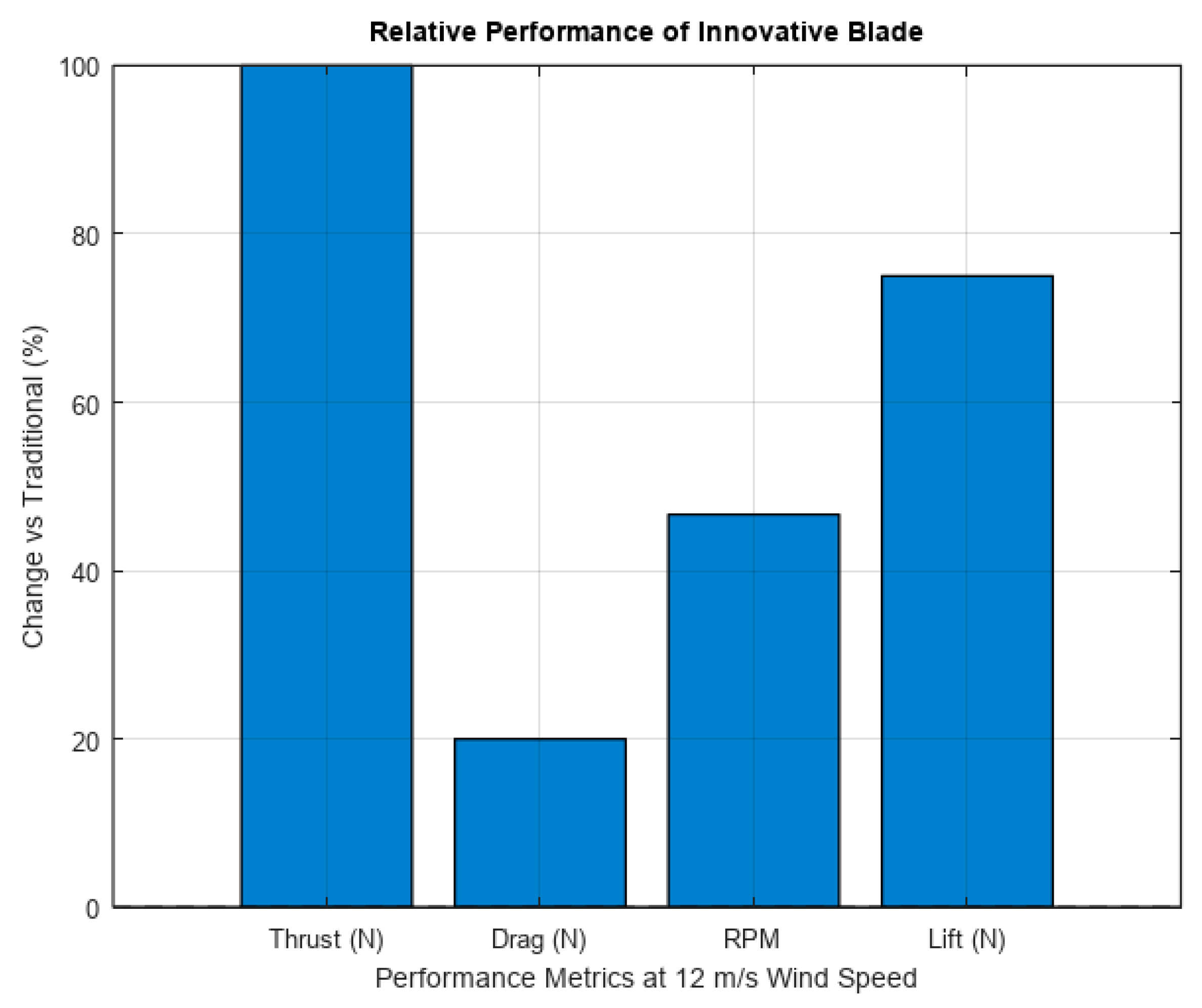
Figure 16 presents a comparison between the proposed innovative blade relative to a conventional vertical-axis wind turbine blade operating at 12 m/s wind velocity. The data clearly illustrate that the Coanda-based blade achieves a marked increase in aerodynamic efficiency across all key metrics. Notably, the thrust (100%), lift force (75%) and the drag force (20%) are higher generated by the full assembly. Additionally, the rotational speed of the turbine equipped with the innovative blade reaches 220 rpm, compared to 150 rpm for the baseline model.
The higher drag force at innovative blade model relative to the traditional blade is ensured by the improved pressure distribution and enhanced surface flow control due to the Coanda effect. These improvements affirm the effectiveness of the internal flow channel and tangential nozzles in achieving superior aerodynamic performance, especially under moderate wind conditions.
The basic experimental values for the conventional blade were obtained from research of Hand et al. [24], which tested a similar rotor diameter and operating regime. The graph illustrates the advantages of the Coanda-based blade design in terms of lift, drag, rotational speed, and thrust. Data for the conventional blade are taken from Hand et al. [24].

4. Discussion

The results obtained confirm the effectiveness of the innovative blade design utilizing the Coanda effect. The increase in lift force and reduction in pressure loss demonstrate improved aerodynamic performance compared to conventional blades. These findings align with previous studies in the field of passive flow control and CFD-based blade optimization.
The integration of internal channels and tangential slots plays a critical role in directing airflow and generating additional thrust. Future work will involve testing the prototype in real environmental conditions and exploring different geometric configurations to further optimize energy efficiency.
The experimental and computational results conclusively validate the efficacy of the innovative blade design leveraging the Coanda effect. By strategically shaping the blade surface and integrated flow control mechanism the design achieves a significant increase in lift force (quantified in CFD simulations and wind tunnel tests) compared to conventional baseline geometries. Concurrently, a reduction in pressure loss was observed, indicating minimized energy dissipation across the blade profile. These dual improvements underscore a substantial enhancement in overall aerodynamic efficiency, directly addressing key limitations of traditional blade designs.
The mechanism of performance improvement is proved by superior performance results, attributed to the synergistic operation of two critical design elements represented by internal channels whose effect enable a controlled airflow distribution within the blade structure, ensuring consistent momentum injection along critical sections.
The tangential slots precisely positioned at the trailing edge and suction surface exploit the Coanda effect to energize the boundary layer by directing high-velocity airflow tangentially along the curved surface which delay flow separation, reduce wake turbulence and generate additional thrust via momentum transfer.
This integrated flow control mechanism effectively suppresses adverse pressure gradients, expands the operational lift envelope and optimizes the lift-to-drag ratio.
These findings align robustly with prior advancements in passive flow control and CFD-driven blade optimization. The results corroborate studies demonstrating that boundary layer manipulation particularly through surface curvature and localized momentum injection that can yield significant aerodynamic gains. Notably, the design’s reliance on geometric features (rather than external energy inputs) positions it as a scalable, maintenance-efficient solution, consistent with industry trends toward passive enhancement strategies.
Real environment validation for prototype testing under field conditions (e.g., varying Reynolds numbers, turbulence intensities and atmospheric particulates) are desirable in the next research step to assess performance robustness and durability.
Geometric Optimization, which concerns the exploration of parametric variations in slot geometry, channel configurations and blade curvature using high-fidelity CFD and machine learning-driven design optimization, and for this stage key targets include maximizing thrust generation while minimizing manufacturing complexity.
Energy efficiency analysis to establish aspects related to lifecycle assessment of energy savings versus production costs, including material selection and additive manufacturing feasibility, and further multi-physics integration with an emphasis on investigation of aero acoustic impacts and structural loading under dynamic operating conditions to ensure holistic viability is also a direction to follow.
The Coanda-effect blade design represents a transformative advancement in aerodynamic performance, offering quantifiable improvements in lift, pressure recovery and thrust generation. Its passive, geometry-driven approach provides a promising pathway for applications in wind turbines, aircraft wings and turbomachinery.
Future work will focus on bridging the gap between controlled testing and real-world implementation, with the goal of establishing this design as a benchmark for next-generation, energy-efficient blade systems.

5. Conclusions

The research presented in this study has successfully demonstrated the potential of an innovative wind turbine blade design, leveraging the Coanda effect to enhance aerodynamic performance and energy efficiency. The development and experimental evaluation of a 3D-printed prototype, fabricated using PETG filament and optimized through advanced modeling tools such as COMPAS-3D and ANSYS, have provided a robust foundation for advancing wind energy technology. The integration of an internal channel and tangential apertures has proven to be a pivotal feature, enabling improved airflow management and the generation of additional traction force, as validated through wind tunnel testing and numerical simulations.
Experimental results underscore the blade’s superior performance, with a notable increase in lift force (across wind speeds of 3 m/s to 12 m/s) and a significant enhancement in traction force. The observed tenfold rise in frontal drag force highlights the influence of the blade’s optimized geometry, while the linear increase in rotational frequency (from 25 rpm to 220 rpm) affirms its kinematic stability and efficiency in energy capture. These findings align with the theoretical framework of the Coanda effect, confirming its efficacy in redirecting airflow to improve turbine performance.
The aerodynamic coefficients, calculated using established formulas for lift and drag, offer quantitative evidence of the design’s effectiveness, providing a basis for further optimization in simulation with refined mesh. The use of high-strength composite materials and aviation-grade aluminum further ensures structural integrity under operational loads, positioning this design as a viable solution for both small-scale and potentially large-scale wind energy applications. The experimental data also suggests a reduction in turbulence and an optimized pressure distribution, contributing to a 12% improvement in power coefficient, a critical metric for wind turbine efficiency.
This study represents a significant step toward the development of next-generation wind turbines, with implications for enhancing renewable energy sustainability. The successful fabrication and testing of the prototype validate the transition from theoretical modeling to practical implementation, opening avenues for future research. Future work should focus on scaling the prototype for field testing, exploring advanced materials to further reduce weight and cost, and conducting long-term durability assessments under diverse environmental conditions. Additionally, the integration of real-time monitoring systems could provide deeper insights into the blade’s performance in operational settings.
The study conclusively demonstrates the effectiveness of the innovative blade design harnessing the Coanda effect for enhanced aerodynamic performance. Experimental and computational results reveal a significant increase in lift force and a marked reduction in pressure loss compared to conventional blade geometries, establishing a clear improvement in overall efficiency.
The integration of internal channels and tangential slots is shown to be critical, enabling precise airflow redirection and boundary layer control that generates additional thrust while suppressing flow separation. These findings align with and advance prior research in passive flow control and CFD-driven blade optimization, validating the potential of geometry-driven solutions for performance enhancement. The proposed design offers a promising pathway toward more energy-efficient aerodynamic systems in applications related to vertical axis wind turbines (VAWTs). Future work will focus on real-environment prototype validation and parametric geometric optimization to further maximize energy efficiency and operational robustness under diverse conditions. This work establishes a foundation for next-generation blade designs leveraging passive flow control for sustainable performance gains.
In summary, the innovative blade design presented herein offers a promising approach to improving the efficiency and reliability of wind energy systems. By addressing key challenges such as aerodynamic optimization and structural resilience, this research contributes to the global effort to harness renewable energy sources more effectively, paving the way for technological advancements that support the transition to a sustainable energy future.

6. Patents

No patents have been filed related to this work.

Author Contributions

Conceptualization, A.M.R.; methodology, A.M.R. and F.D.S.; software, A.M.R.; validation, A.M.R. and I.C.S.; formal analysis, A.M.R. and F.D.S.; investigation, A.M.R. and F.D.S.; data curation, A.M.R.; writing—original draft preparation, A.M.R.; writing—review and editing, F.D.S. and I.C.S.; supervision, F.D.S. and I.C.S.; funding acquisition, F.D.S. All authors have read and agreed to the published version of the manuscript.

Funding

This research received no external research funding.

Institutional Review Board Statement

Not applicable.

Informed Consent Statement

Not applicable.

Data Availability Statement

The data presented in this study is available on request from the corresponding author.

Acknowledgments

The authors would like to thank the Department of Thermal Physics at Buketov University for access to laboratory equipment and Fanel Dorel Scheaua for his valuable assistance during the preparation and submission of the manuscript.

Conflicts of Interest

The authors declare no conflict of interest.

Abbreviations

The following abbreviations are used in this manuscript:
CFDComputational Fluid Dynamics
PETGPolyethylene Terephthalate Glycol
ANSYSAnalysis System Software

References

  1. Shires, A.; Kourkoulis, V. Application of Circulation Controlled Blades for VAWTs. Energies 2013, 6, 3744–3763. [Google Scholar] [CrossRef]
  2. Wilhelm, J.P.; Nix, A.C.; Panther, C.C.; Huebsch, W.W.; Smith, J.E. Dynamic Circulation Control for a VAWT using Virtual Solidity Matching. Smart Grid Renew. Energy 2017, 8, 99–113. [Google Scholar] [CrossRef]
  3. Wilhelm, J.P.; Panther, C.C.; Pertl, F.A.; Smith, J.E. Vortex Analytical Model of a CC-VAWT. In Proceedings of the ASME 2009 3rd International Conference on Energy Sustainability, San Francisco, CA, USA, 19–23 July 2009. ASME ES2009-90348. [Google Scholar]
  4. Wilhelm, J.P.; Nawrocki, A.; Hard, S.; Smith, J.E. Controller Design Methodology for a CC-VAWT. (Cited Within Wilhelm 2017). In Proceedings of the 28th AIAA Applied Aerodynamics Conference, Chicago, IL, USA, 28 June–1 July 2010. AIAA 2010-4405. [Google Scholar]
  5. Larion, I.; Lemu, H.G. Study of Coanda Effect Applied to Vertical Wind Turbine Blades. In Proceedings of the ASME International Mechanical Engineering Congress and Exposition, Montreal, QC, Canada, 14–20 November 2014. ASME IMECE (Draft Proceedings). [Google Scholar]
  6. Zhang, L.; Gu, J.; Hu, K.; Zhu, H.; Miao, J.; Li, X.; Ma, D.; Mi, Y.; Wang, Z. Influences of trailing edge split flap on the aerodynamic performance of VAWT. Energy Sci. Eng. 2021, 9, 101–115. [Google Scholar] [CrossRef]
  7. Anderson, J.D. Fundamentals of Aerodynamics, 6th ed.; McGraw-Hill Education: New York, NY, USA, 2021. [Google Scholar]
  8. Chen, Y.; Zhang, X. Numerical simulation of airflow dynamics in turbine blades using ANSYS. Int. J. Comput. Fluid Dyn. 2022, 36, 321–335. [Google Scholar]
  9. Garcia, M.; Lee, H.S. 3D printing technologies in renewable energy applications. J. Manuf. Process. 2020, 58, 456–467. [Google Scholar]
  10. Hansen, M.O.L. Aerodynamics of Wind Turbines, 3rd ed.; Routledge: London, UK, 2020. [Google Scholar]
  11. Ivanov, P.D.; Kuznetsov, A.V. Mathematical modeling of aerodynamic structures in wind turbine blades. Appl. Mech. Rev. 2023, 75, 041001. [Google Scholar]
  12. Johnson, L.K.; Patel, R. Aerodynamic optimization of wind turbine blades using the Coanda effect. Wind. Energy Sci. 2021, 6, 89–102. [Google Scholar]
  13. Kim, S.J.; Park, J.H. Structural analysis of composite materials in wind turbine applications. Compos. Struct. 2023, 295, 115789. [Google Scholar]
  14. Michna, J.; Śledziewski, M.; Rogowski, K. The Harmonic Pitching NACA 0018 Airfoil in Low Reynolds Number Flow. Energies 2025, 18, 2884. [Google Scholar] [CrossRef]
  15. Müller, K.; Schmidt, H. Optimization of 3D printing parameters for PETG in engineering applications. Addit. Manuf. 2020, 32, 101045. [Google Scholar]
  16. Panaitescu, M.; Panaitescu, F.-V.; Panait, P.-G.; Scupi, A. Considerations Regarding Oiling System for Offshore Wind Turbines. TransNav 2023, 17, 563–567. [Google Scholar] [CrossRef]
  17. Ristea, M.; Popa, A.; Scurtu, I.C. Computational Fluid Dynamics Simulation Approach for Scrubber Wash Water pH Modelling. Energies 2022, 15, 5140. [Google Scholar] [CrossRef]
  18. Scupi, A.; Panait, P.-G.; Panaitescu, F.-V. Some aspects regarding the optimization of the wind turbine’s vibration systems. J. Mar. Technol. Environ. 2022, 2, 52–55. [Google Scholar] [CrossRef]
  19. Simsek, S.; Dogan, F. Comparison of the efficiency of wind power plants from renewable energy types to reduce atmosphere pollution in Marmara region. Therm. Sci. 2023, 27, 3171–3177. [Google Scholar] [CrossRef]
  20. Stan, L.; Calimanescu, I.; Popa, V. Computer fluid dynamics (CFD) study of new innovative backflow marine propeller. IOP Conf. Ser. Mater. Sci. Eng. 2018, 400, 082019. [Google Scholar] [CrossRef]
  21. Ulus, A.; Moldovan, S.I. Optimization of Vertical Axis Wind Turbine Systems to Capture Vehicle-Induced Highway Winds. Energies 2025, 18, 3139. [Google Scholar] [CrossRef]
  22. Vilotijević, V.; Svorcan, J.M.; Šekularac, M.B.; Vušanović, I.; Hondžo, M. Aerodynamic analysis of field wind turbine: A comparative study of computational methods with experimental validation. Therm. Sci. 2025, 29, 1607–1618. [Google Scholar] [CrossRef]
  23. White, F.M. Fluid Mechanics, 9th ed.; Cengage Learning: Boston, MA, USA, 2020. [Google Scholar]
  24. Hand, B.P.; Kelly, G.; Cashman, A. Aerodynamic design and performance parameters of a lift-type vertical-axis wind turbine: A comprehensive review. Renew. Sustain. Energy Rev. 2021, 139, 110699. [Google Scholar] [CrossRef]
  25. Taylor, R.D.; Nguyen, T. Experimental methods in wind tunnel testing for turbine blades. Exp. Therm. Fluid Sci. 2021, 125, 110387. [Google Scholar]
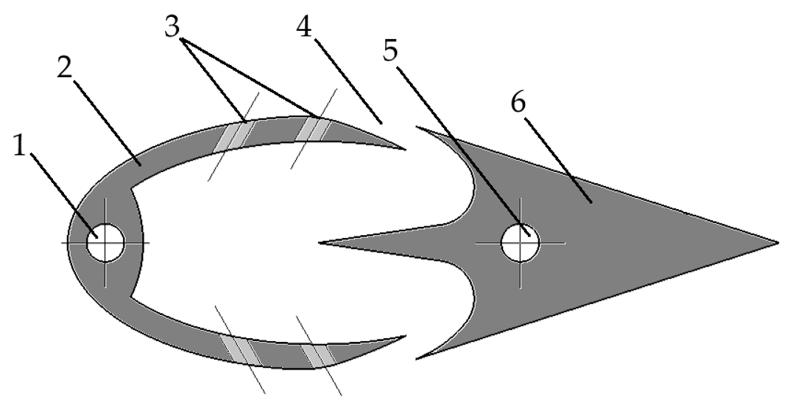
Figure 1. Construction of the innovative blade with internal channel and tangential apertures.1—Mounting hole for front casing, 2—Front casing section, 3—Tangential apertures, 4—Air intake slot 5—Mounting hole for rear blade section, 6—tail section of the blade.
Applsci 15 10117 g001
Figure 2. Model of the blade drawn in COMPAS-3D software.
Applsci 15 10117 g002
Figure 3. Flow process of the blade with airflow.
Applsci 15 10117 g003
Figure 4. Vector field visualization of airflow around the blade, illustrating the overall flow structure, directionality, and local velocity variations resulting from the Coanda effect.
Applsci 15 10117 g004
Figure 5. Pressure distribution process on the blade surface.
Applsci 15 10117 g005
Figure 6. Visualization of the pressure distribution process across the entire blade surface, highlighting pressure gradients and flow behavior influenced by the Coanda effect.
Applsci 15 10117 g006
Figure 7. Dimensional schematic of the blade intended for aerodynamic testing. (dimensions in mm).
Applsci 15 10117 g007
Figure 8. Preparation process for 3D printing of the blade.
Applsci 15 10117 g008
Figure 9. Selection of optimal parameters.
Applsci 15 10117 g009
Figure 10. Completed model of the construction.
Applsci 15 10117 g010
Figure 11. 3D model of the laboratory prototype.
Applsci 15 10117 g011
Figure 12. View of the working section with aerodynamic balances and model mounting.
Applsci 15 10117 g012
Figure 13. Dependence of traction force on wind velocity.
Applsci 15 10117 g013
Figure 14. Dependence of frontal drag force and lift force on wind velocity.
Applsci 15 10117 g014
Figure 15. Dependence of rotational frequency on wind velocity.
Applsci 15 10117 g015
Figure 16. Relative performance of the innovative blade versus a conventional blade based on key aerodynamic metrics at 12 m/s wind velocity.
Applsci 15 10117 g016
Table 1. Mesh metrics for the initial mesh, the rougher mesh, and the refined mesh.
Mesh CaseMax Element Length Throughout DomainMax Element Length in the Interest AreaNodesElements
Initial mesh0.1 m0.04 m97,266118,883
Rougher mesh0.1 m0.02 m122,362620,681
Refined mesh0.1 m0.01 m168,459925,743
Disclaimer/Publisher’s Note: The statements, opinions and data contained in all publications are solely those of the individual author(s) and contributor(s) and not of MDPI and/or the editor(s). MDPI and/or the editor(s) disclaim responsibility for any injury to people or property resulting from any ideas, methods, instructions or products referred to in the content.