Article

Study on Surrounding Rock Failure Analysis and Novel Stability Control Approach for High-Stress Gob-Side Roadway Retaining

1
China Coal Research Institute, Beijing 100013, China
2
State Key Laboratory of Hydroscience and Engineering, Tsinghua University, Beijing 100084, China
*
Authors to whom correspondence should be addressed.
Appl. Sci. 2025, 15(18), 10119; https://doi.org/10.3390/app151810119
Submission received: 25 August 2025 / Revised: 14 September 2025 / Accepted: 16 September 2025 / Published: 16 September 2025
(This article belongs to the Section Civil Engineering)

Abstract

The high stress environment and hard roof conditions seriously limit the application of gob-side roadway retaining. To achieve non-coal pillar mining, this study proposes a novel method combining roadside filling and roof cutting under stress-release and strong support synergy. Mechanical modeling reveals surrounding rock failure mechanisms in high-stress gob-side roadway retaining. Numerical simulations show the new method reduces surrounding rock stress/displacement more effectively than conventional gob-side roadway retaining. Optimized parameters were validated via field tests, confirming significant control of rock deformation under complex high-stress conditions. The method successfully enables non-coal pillar mining, providing a scientific basis for similar applications.

1. Introduction

Coal, as the main energy source in China, dominates its energy structure. According to statistics, coal consumption is expected to account for more than 50% of primary energy consumption by 2030 [1,2,3]. As the “ballast stone” of energy security, the intensive mining and efficient utilization of coal resources are crucial to guarantee national energy security and sustainable development [4,5,6,7]. However, traditional long-wall mining methods commonly retain coal pillars to protect the roadway, which leads to a permanent loss of approximately 10–30% of coal resources due to coal pillar retention [8,9,10], and exacerbates the problems of tense mining succession and high roadway excavation costs [11,12]. Against this background, gob-side roadway retaining through roadside filling technology has emerged, which replaces coal pillars with flexible formwork filling bodies, reducing the waste of resources, alleviating the contradiction between mining and excavation, and becoming an important way to realize non-coal pillar mining [13,14,15,16]. However, the existing gob-side roadway retaining through roadside filling technology mostly adopts the rigid support concept, so the high strength of the filling body can easily cause stress concentration, resulting in increased deformation of the surrounding rock of the roadway. In particular, under deep high stress or hard roof conditions, the deformation of the floor and the convergence of the two sides are significant, which seriously restricts the reuse of the retained roadway [17,18,19]. Balancing the synergistic relationship between stress control and support strength in gob-side roadway retaining has become the key to optimizing this technology.
The existing research on the gob-side roadway retaining technology mainly focuses on two directions: one is the roadside support reinforcement technology with flexible formwork filling as the core, and the other one is the self-forming roadway through roof cutting and pressure relief technology with the goal of stress regulation. Scholars have conducted systematic research on material properties and support parameters in terms of gob-side roadway retaining using roadside filling technology. Deng and Li [20] used CO2 mineralized filling material as flexible formwork filling aggregate, improving the performance of the filling body, reducing the stress of the surrounding rock in the fracture zone, and enhancing the stability of roadway support. In terms of the issue of instability of the filling body during large mining height gob-side roadway retention, Pu et al. [21] established a mechanical model and numerical simulation to determine the appropriate width of the filling body, revealing that a reasonable increase in width can improve shear resistance and reduce surrounding rock stress. Zhu et al. [22] enhanced the load-bearing capacity of flexible formwork concrete using a Z6 concrete reinforcement agent, suppressing the two-stage expansion of the over-limit length of the filling body under secondary mining, and ensuring the structural integrity and load-bearing stability of the gob-side roadway retaining without coal pillars under dynamic mining loads. However, such technologies focus on passive resistance to mining pressure and do not alleviate the problem of stress concentration in the surrounding rocks, making it difficult to adapt to high stress and complex geological conditions. In terms of self-forming roadways through roof cutting and pressure relief technology, Wang et al. [23] proposed a synergistic control method involving roof cutting, pressure relief, and energy-absorbing reinforcement to address mining-induced seismicity and roof overhang issues resulting from the difficult caving of thick and hard roofs in coal mines. They verified the effectiveness of this technology through field applications, demonstrating its capability to reduce roof peak stress and floor deformation, thereby offering a viable solution for similar engineering challenges. Meanwhile, Gao et al. [24] investigated the mechanical behavior of roadways formed by roof cutting in fault zones through field tests and numerical simulations. They developed corresponding support techniques and validated their reliability, thus providing a theoretical basis for optimizing non-pillar mining technology under complex geological conditions. Yang et al. [25] proposed a new method for gob-side roadway retention based on the short cantilever beam theory, achieving the stability control of the roadway surrounding rock through directional blasting split roof technology, dynamic support system of yielding anchor cables, and U-shaped steel gangue wall construction technology. Wang et al. [26] proposed a non-coal pillar pressure relief mining technology, which integrates four core technologies including liquid directional roof cutting and constant resistance anchor support, achieving the goal of no advance roadway and coal pillar in field applications. Moreover, the dual advantages of the proposed technology in improving the resource recovery rate and controlling the stability of the surrounding rock were verified through monitoring. Meanwhile, in addition to the blast-induced roof cutting method mentioned above, there is also the hydraulic fracturing method. This technique enables the fracturing and cutting of hard rock without the use of explosives, which is of great significance for environmental protection. However, these technologies rely on multi-process collaboration for roadside support, which makes construction difficult and has high requirements for construction quality. Moreover, insufficient strength of the roadside support can easily cause asymmetric subsidence of the roof, threatening the long-term stability of the roadway.
In summary, there are limitations in single roadside filling, roof cutting, and pressure relief technology. The former relies excessively on high-strength supports, especially under hard roof conditions, and cannot reduce the stress of the surrounding rock from the source. Although the latter focuses on stress regulation, it has a weak support system and involves complex processes. Therefore, there is an urgent need to explore a synergistic control method that integrates the advantages of stress release and strong support. In this study, a synergistic control technology for roadside filling and roof cutting and pressure relief is proposed, which guides the transfer of mining stress to deep areas through roof cutting and pressure relief, and achieves roadside support combined with the deformation characteristics of the filling body, forming a “relief-support” dynamic balance system. The synergistic control mechanism was systematically analyzed in this study by taking the 90105 working face of Dongsheng Coal Mine as the engineering background, and the control effects were compared and studied. Field tests were conducted to provide a theoretical foundation and technical reference for the stability control of gob-side roadway retention under high stress conditions.

2. Engineering Overview

2.1. Geological Conditions of the Engineering

The test coal mine is located in Changzhi City, Shanxi Province, China, and has an annual production capacity of 900,000 tons. At present, No. 9 and 10 horizontal coal seams are being mined with a burial depth of 510.56 m. The thickness of the coal seam was 2.00–4.03 m, with an average of 2.65 m. The mining method is a one-time full-height mining method that uses an integrated mechanized mining method. The test working face was the 90105 working face, located in the eastern wing mining area of this mine, adjacent to the 90103 mining face on the west side and the 90106 mining face on the east side. The mineable length of the test working face was 883 m, and the length of the working face was 260 m. The false roof of the coal seam is a thin layer of mudstone with an average thickness of 0.2 m, and the direct roof is dark gray K2 limestone with an average thickness of 8.51 m. Rock is relatively hard and prone to collapse. The main roof was mudstone with an average thickness of 12.31 m. The direct floor is mudstone with an average thickness of 9.46 m. The test roadway was a 90105 belt roadway, excavated along the coal seam floor. The layout of the test working face is shown in Figure 1.

2.2. Engineering Problems

The original height and width of the test working face roadway were 3 and 5 m, respectively, and the gob-side roadway retaining through roadside filling technology was used for mining. The roadside was filled with concrete with a width of 1 m, and the roadway height and width were maintained at 3 m and 3.7 m, respectively, to meet the ventilation requirements. Only roadside concrete filling technology was used for the first 200 m. Owing to the hard limestone roof and mining conditions, the roadway retaining the surrounding rock and floor is severely deformed, resulting in a large amount of floor heave, affecting the production of the working face, and increasing the maintenance costs. The lithological column and field failure conditions of the test working face are shown in Figure 1.

3. Key Technology and Control Principle

3.1. Roadside Filling Technology

Roadside filling is a common technique used in the operation of gob-side roadway retention during coal mining. After the working face is mined, a roadside filling wall is constructed along the edge of the goaf to isolate the goaf, support roadway roof, and control the roof subsidence [27,28]. Roadside filling technology controls the stability of the surrounding rock through the synergistic effect of flexible formwork and filling materials [29,30], which uses a flexible formwork of a three-dimensional textile fiber formwork to construct a dynamic load-bearing system combined with an internal prestressed anchor cable mesh. The flexible formwork adopts high-strength tear resistant composite materials, and its axial tensile and radial deformation characteristics can adapt to the non-uniform deformation caused by mining stress. A filling body connected to the roof and floor is formed by pouring early strength and micro expansion concrete, and the deformation energy absorption characteristics of the flexible formwork are utilized to buffer the surrounding rock pressure, while maintaining the overall stability of the structure through the anchor cable mesh truss effect. This technology combines the isolation and support functions of traditional filling walls with the stress control capability of flexible structures, which can block the intrusion of goaf gangue, adapt to roof subsidence and optimize the load transmission path. The technical principles are illustrated in Figure 2.

3.2. Roof Cutting and Pressure Relief Technology

To avoid damage to the integrity of the roadway roof and to cut off the connection between the roadway roof and the goaf roof, Academician He Manchao proposed a bidirectional energy gathering blasting technology based on the mechanical properties of rock resistance to compression but not tension [31,32]. The core of this technology lies in the application of a specific energy gathering device, which is designed as a tubular shape with circular energy gathering holes symmetrically distributed on both sides. When explosives are loaded and detonated, the blasting shock wave is guided through energy gathering holes to generate a concentrated tensile stress field in the energy gathering direction. When the tensile stress exceeds the tensile strength of the rock, cracks propagate along the design direction and penetrate adjacent blast holes, forming a continuous pressure relief face. This face cuts off the continuity of the roof rock layer, causing the collapse of the goaf roof along the pressure relief face, cutting the long cantilever beam into short beams, cutting off the stress transmission path of mining, and achieving the goal of reducing the stress of the roadway surrounding rock and protecting the roadway. The technical principles are illustrated in Figure 3.

3.3. Synergistic Control Method and Principle

When the coal seam roof cannot collapse in time with the mining of the working face because it is hard, the goaf forms a large area of overhanging roof, which can easily cause the working face to be under high-intensity mining conditions, and the roadway is in a high-stress environment. At this time, it is difficult to resist mining pressure by using only a single roadside support to support the roof, which can easily cause large deformation of the rock surrounding the roadway. Therefore, To control the deformation of the surrounding rock of the gob-side roadway retaining under the hard roof condition and reduce the damage of mining pressure to the surrounding rock of gob-side roadway retaining, the roof cutting and pressure relief technology is designed based on the implementation of roadside filling technology, and a new method of gob-side roadway retention through roadside filling and roof cutting is proposed combined with the advantages of the two technologies. The synergistic control method is shown in Figure 4.
According to the theories of “voussoir beam” and “transfer rock beam”, after the mining of the working face, one end of the main roof above the roadway will fracture inside the coal body, and a rotary subsidence will occur around the fracture position, while the other end will sink and gradually compact with the collapsed gangue, eventually forming a balanced rock block structure with one end supported by solid coal and the other end supported by gangue, making the roadway retained in a stable state. The direct roof of the roadway can be regarded as a cantilever beam structure with one end stably connected to the rock layer and the other end open, which maintains balance under the combined action of coal support, roadway support, and overburden layer deformation. Through simplification, the subsidence of the cantilever beam roof structure in the roadway can be solved as a plane strain problem in elastic mechanics. As the stiffness of the fractured rock block in the main roof is much greater than that of the cantilever beam roof, the rotary subsidence of the fractured rock block can be regarded as a given deformation displacement condition applied to the upper boundary of the cantilever beam structure, while the lower boundary is subject to the resistance of anchor support and filling support, and corresponding stress boundary conditions can be given. The left boundary can be regarded as a fixed boundary as it is connected to the deep stable rock mass. The right boundary can be regarded as a free boundary as it is in an open state. Based on this, a mechanical model of the cantilever beam roof structure for gob-side roadway retaining through roadside filling and gob-side roadway retaining through roadside filling and roof cutting is established, as shown in Figure 5.
According to the above model, the cantilever beam deformation problem can be transformed into a plane strain problem in elastic mechanics. Because the model belongs to the mixed boundary conditions of stress and deformation, the displacement variational method was adopted for the solution [33].
Firstly, the displacement component expression that satisfies the boundary conditions is constructed:
u = A x , v = x tan θ + B x ( b y )
where u and v are the displacement coordinate functions in the x and y directions, respectively, and A and B are two independent undetermined coefficients.
Elastic body strain energy U:
U = E 1 μ 2 2 1 μ 2 1 2 μ D u x 2 + v y 2 + 2 μ 1 μ u v x y + 1 2 1 μ u x + v y 2 d x d y
where E is the modulus of elasticity of the rock mass, MPa; μ is Poisson’s ratio of the rock mass; D is the integral region.
The displacement variational equation was established for coefficients A and B using the Rayleigh-Ritz method:
U A = D f x u d x d y   +   S f x ¯ u d s U B = D f y v d x d y   +   S f y ¯ v d s
where f x and f y are the physical force components in the x and y directions of the elastic body; respectively f x ¯ and f y ¯ are the surface force components in the x and y directions on the boundary; S is the integral boundary.
The mechanical model parameters and boundary conditions of two different gob-side roadway retaining methods are substituted into, respectively (1), (2), and (3) to obtain the general calculation formula for the final subsidence of the roadway roof:
v = x tan θ i + 1 μ μ 1 4 ρ g L i 2 b + 1 2 a 2 p z + 2 a l + l 2 p l 2 M + 3 1 2 μ L i μ b tan θ i 4 8 μ + μ 2 L i 3 + 2 1 2 μ 1 μ L i b 2 x b y
where M = 12 μ(1 + μ)(1 − 2 μ)/E; Li = L1 or L2; θi = θ1 or θ2.
Based on the above theoretical calculation results, the calculation formulas for the roof subsidence of the two gob-side roadway retaining methods have a high degree of unity. Although there are many factors affecting the roof subsidence, the main influencing factors that cause the difference in roof subsidence between the two gob-side roadway retention methods can be attributed to the: rotation angle θ; roof length L; roof thickness b. However, it is often difficult to take the values of these factors in practical engineering, making it impossible to solve the problem of roof subsidence. To address this problem, the concept of sensitivity is introduced, that is, the sensitivity coefficient is used to represent the ability of various influencing factors to change the roof subsidence, so as to carry out a qualitative comparison of the roof subsidence for different gob-side roadway retaining methods based on changes in the main influence factors.
The sensitivity coefficient of factors affecting roof subsidence is defined as follows:
S i = Δ v / v i / Δ f / f i
where S i is the sensitivity coefficient, Δ v / v i is the rate of change in roof subsidence Δ f / f i is the rate of change in each influencing factor.
If S i is positive, it indicates a positive correlation between its influencing factors and roof subsidence, and vice versa. S i is its degree of sensitivity, and the values of the influencing factors are also related to their sensitivity coefficient; Therefore, the sensitivity coefficient of the influencing factors is within a certain range of change. Table 1 shows the sensitivity coefficients of the main influencing factors of roof subsidence determined based on the geological conditions of the 90105 working face in the Dongsheng Coal Mine.
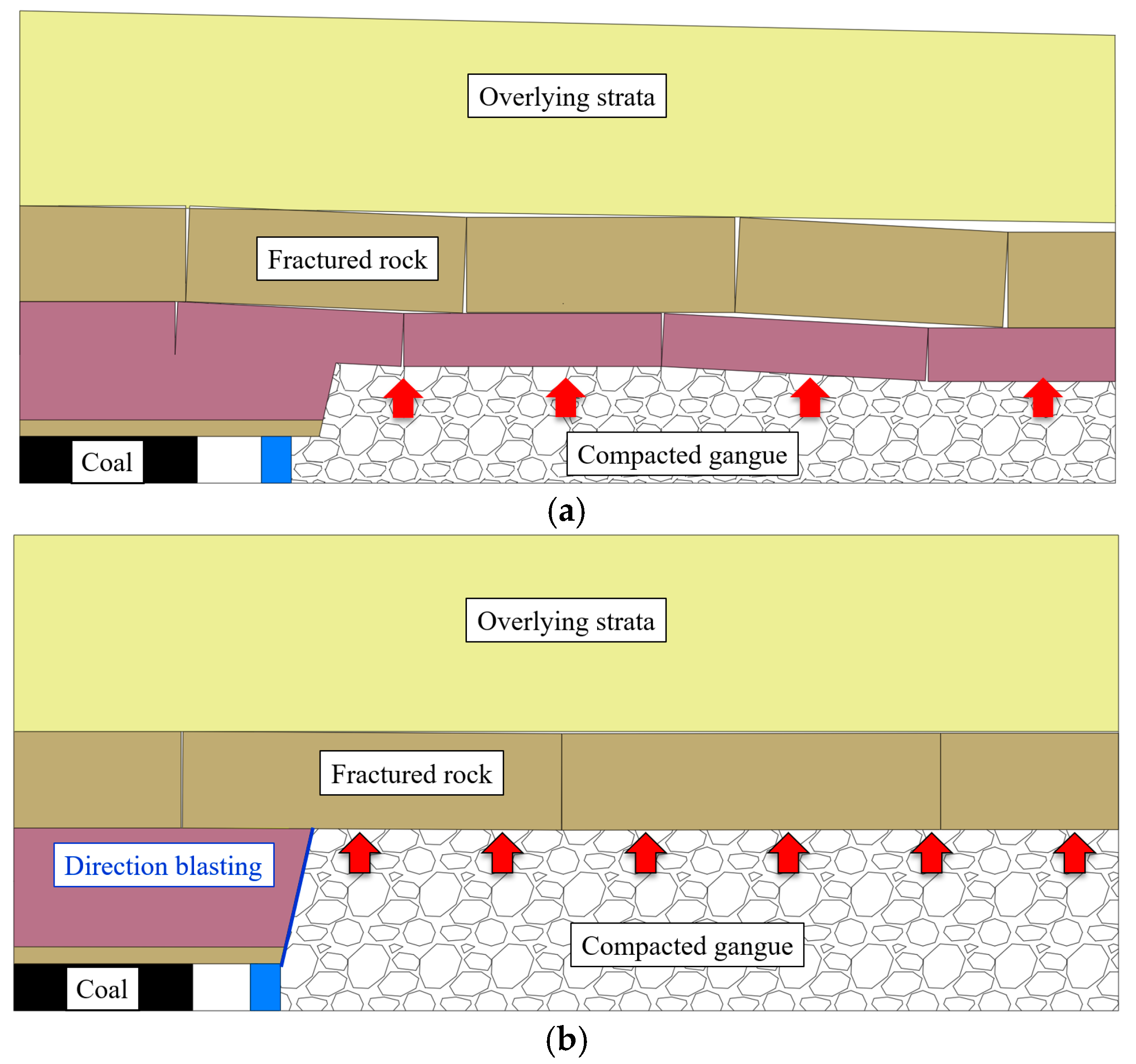
As shown in Figure 6a, owing to the relatively small roof collapse height for the gob-side roadway retaining through roadside filling, the fragmented and expanded gangue in the goaf cannot effectively fill the goaf, which results in weak support for the goaf roof, This leads to an increase in the rotation angle θ1 of the fractured rock block, a decrease in the thickness b1 of the roadway roof, and the cut off of the roadway in the goaf. Therefore, the roof length L1 = a + l + l0. As shown in Figure 6b, the gob-side roadway retaining through roadside filling and roof cutting technology increases the roof collapse height through roof cutting, so that the fragmented and expanded gangue can fill the roadside goaf, which provides effective support for the goaf roof, leading to a decrease in the rotation angle θ2 of the fractured rock block, an increase in the thickness b2 of the roadway roof, the cutoff of roadway roof by directional roadside blasting, and formation of a short beam structure with a roof length L2 = a + l. Therefore, the relationship between the rotation angles of the fractured rock blocks in the two gob-side roadway retaining techniques is: θ1 > θ2; the relationship between the roof thickness is: b1 < b2; and the relationship between the roof length is L1 > L2.
The greater the subsidence of the roof, the greater the stress on the filling and the greater the stress on the surrounding rock of the roadway. The relationship between the factors affecting the roof subsidence under two the gob-side roadway retaining methods is as follows: rotation angle θ1 > θ2, roof length L1 > L2, and roof thickness b1 < b2. However, as indicated in Table 1, the sensitivity coefficients of the roof length and rotation angle are significantly greater than those of the roof thickness, so compared to the roof length and rotation angle, the roof thickness has little effect on the roof subsidence. According to the comparative analysis, compared to the gob-side roadway retaining through roadside filling without roof cutting technology, the gob-side roadway retaining through roadside filling and roof cutting technology can significantly reduce the roadway roof subsidence, reducing the stress on the filling body and achieving the goal of optimizing the stress environment of the roadway surrounding rock.

4. Control Effects

To clarify the technical principle of gob-side roadway retention through roadside filling and roof cutting methods, comparative research on numerical simulation was carried out to further clarify the control effects and key design parameters of this method, providing scientific guidance for verifying its effectiveness and conducting field tests.

4.1. Model Established

In order to comparatively study the control effects of gob-side roadway retaining through roadside filling and gob-side roadway retaining through roadside filling and roof cutting, a numerical model was established using FLAC3D V4.0 numerical simulation software based on the geological conditions of Dongsheng Coal Mine, as shown in Figure 7. The model had a length of 520 m, width of 400 m, and height of 100 m. The length of the 90105 working face was 260 m and the width of the 90106 working face was 174 m. A vertical stress of 11 MPa was applied at the upper boundary of the model. The lower boundary was vertically fixed. The front, back, left, and right boundaries were horizontally fixed. A trapezoidal distributed load is applied horizontally. All entries were designed to be 5 m (width) × 3 m (height). The rock mechanics parameters were obtained based on the drilling data and indoor rock mechanics tests of the 90105 working face of the Dongsheng Coal Mine, as shown in Table 2. The simulation involved first excavating two roadways in the 90105 working face, followed by a step-by-step excavation of the working face. As the working face is excavated, filling bodies are constructed in the goaf while directional blasting is performed. A comparative analysis was conducted on the stress, displacement, and plastic zone characteristics of the rock surrounding the roadway when the working face was mined to a depth of 200 m.

4.2. Effect Analysis

4.2.1. Analysis of Surrounding Rock Stress

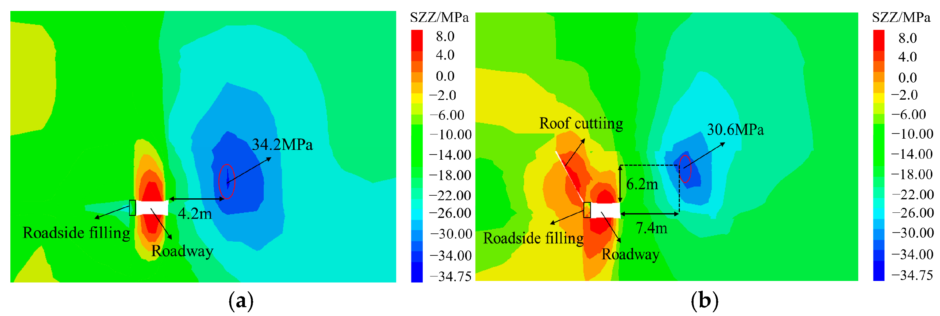
A comparative analysis was conducted on the stress of the rock surrounding the roadway when the working face was mined to a depth of 200 m. The surrounding rock stress of the gob-side roadway retained through roadside filling is shown in Figure 8a, indicating that there is a large-scale stress concentration on the solid coal side, with a peak stress concentration of 34.2 MPa, and the peak is relatively close to the coal side position, only 4.2 m. When the gob-side roadway retaining through roadside filling and the roof cutting method is used, as shown in Figure 8b, it can be seen that the range of the stress concentration zone on the solid coal side has significantly decreased, with the peak stress concentration reduced to 30.6 MPa, and the peak location was further away from the roadway to 7.4 m. Compared with the gob-side roadway retaining through roadside filling without roof cutting technology, the peak stress was reduced by 10.5%, and the peak distance increased by 76.1%, indicating that the roof cutting technology successfully cut the long cantilever beam into short beams, blocked the stress transmission path, transferred the stress concentration zone away from the roadway, optimized the stress environment of the roadway surrounding rock, and ensured the stability of the roadway surrounding rock.

4.2.2. Analysis of Surrounding Rock Deformation

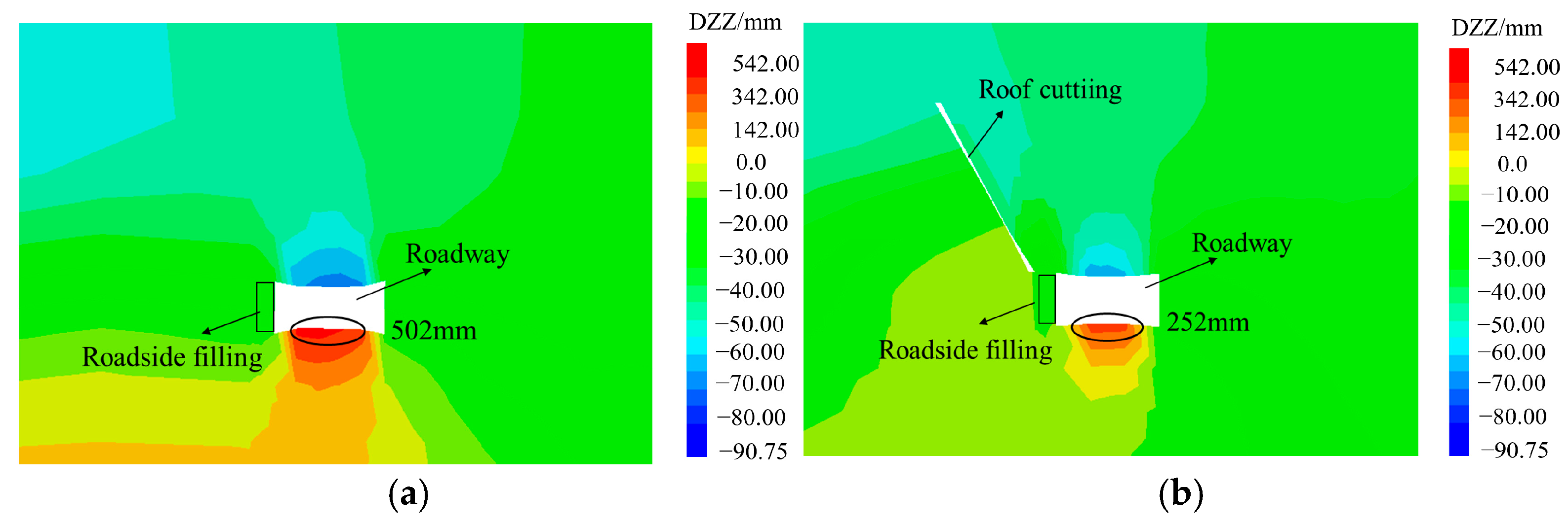
A comparative analysis was conducted on the deformation of the rock surrounding the roadway when the working face was mined to a depth of 200 m. The surrounding rock deformation of the gob-side roadway retaining through roadside filling is shown in Figure 9a, indicating that: the deformation mainly occurs on the floor, with a maximum deformation of 502 mm for the floor and 90 mm for the roof, which indicates that the filling support is very effective in controlling the roof deformation, However, owing to the inability to release stress, it ultimately manifests in the form of floor deformation. When the gob-side roadway retaining through roadside filling and roof cutting method is used, as shown in Figure 9b, it can be observed that the deformation still mainly occurs on the floor, with the maximum deformation of the floor reduced to 252 mm, and the deformation of the roof was slightly reduced, with a maximum deformation of 63 mm. Compared with the gob-side roadway retaining through roadside filling without roof cutting technology, the maximum deformation of the floor and roof was reduced by 50.2% and 30%, respectively, indicating that the roof cutting technology successfully released the stress of the roadway surrounding rock, reducing the deformation of the roadway floor and roof. Therefore, the new method effectively controls the surrounding rock deformation, maintaining the roadway surrounding rock deformation within the requirements of roadway retention for reuse.

4.2.3. Analysis of the Surrounding Rock Plastic Zone

A comparative analysis was conducted on the plastic zone of the rock surrounding the roadway when the working face was mined to a depth of 200 m. The surrounding rock plastic zone of the gob-side roadway retaining through roadside filling is shown in Figure 10a, indicating that: the filling body is basically in a plastic state, and the surrounding rock plastic zone around the roadway is relatively large, with the maximum plastic zone on the solid coal side and roof side of 8.5 m and 7.4 m, respectively. When the gob-side roadway retaining through roadside filling and roof cutting method is used, as shown in Figure 10b, it can be seen that: only 40% of the filling body is in a plastic state, and the surrounding rock plastic zone around the roadway is significantly reduced, with the maximum plastic zone on the solid coal side and roof side reduced to 6.5 m and 5.4 m, respectively. The plastic zone range of the filling body decreased by nearly 50%, and the maximum plastic zone range of the solid coal side and roof side decreased by 23.5% and 27%, respectively, This indicates that the roof cutting technology has cut off the long cantilever beam, reducing the stress on the filling body, improving the stress state of the roadway surrounding rock, further decreasing the roadway surrounding rock plastic zone, and achieving effective control of the surrounding rock deformation.

4.3. Analysis of Key Parameters

4.3.1. Analysis of Filling Body Parameters

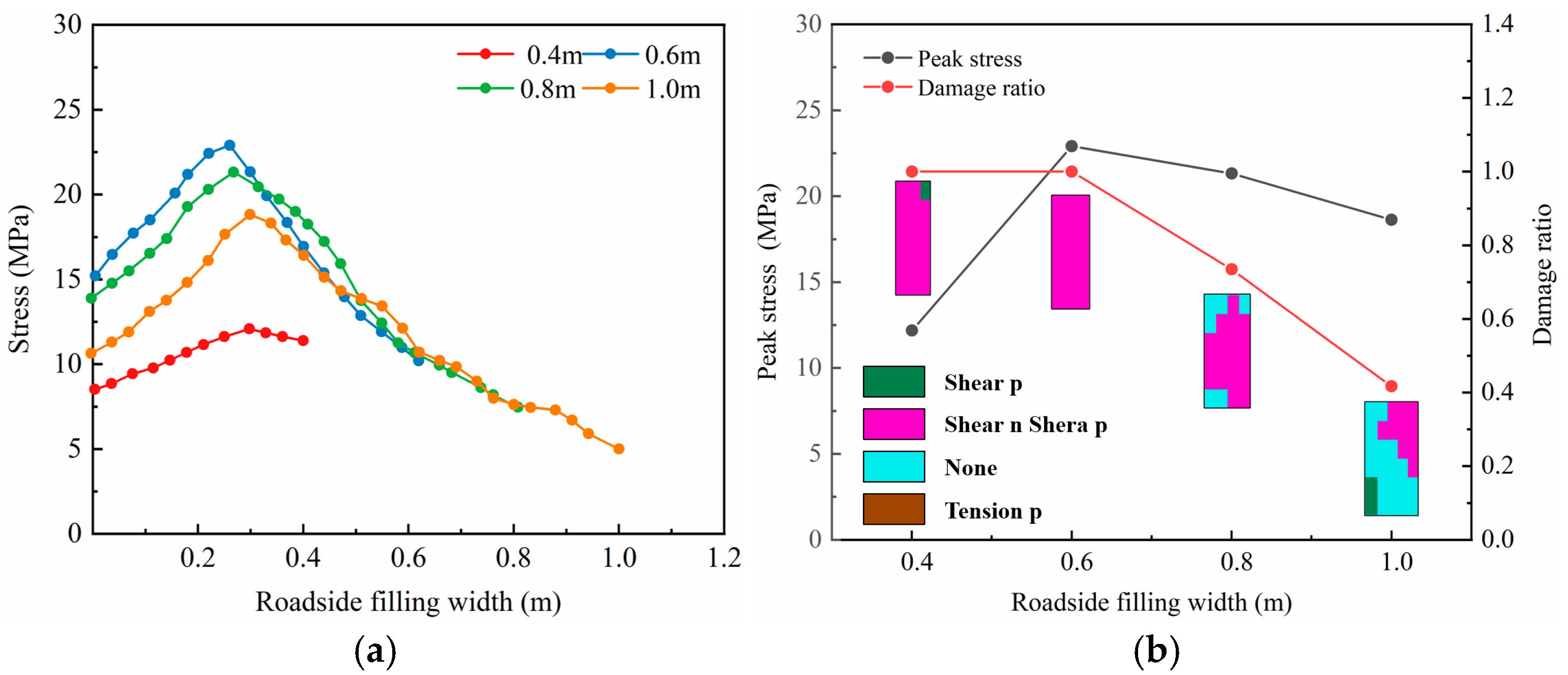
The size of the roadside filling body is crucial for controlling the roadway surrounding rock deformation, and the height of the filling body should be consistent with the height of the roadway. Comparative research has been conducted on its width. Four comparative studies were conducted while controlling the fixed roof cutting parameters, with widths of (a) 0.4 m, (b) 0.6 m, (c) 0.8 m, and (d) 1.0 m, respectively. Figure 11a,b reveals the distribution law and degree of damage and failure of the vertical stress field inside the roadside filling body with different widths. It can be seen that the vertical stress curve exhibits a typical unimodal distribution, and its peak characteristics show a nonlinear evolution law: During the increase in the width of the filling body from 0.4 m to 1.0 m, the stress peak exhibits a three-stage evolution characteristic of increase—decrease—re-increase. Among them, the degree of stress concentration is the lowest at a width of 0.4 m, but the degree of damage reveals that the reason for the low peak is that the filling body was completely damaged, and the load-bearing capacity decreased. When it reaches 0.6 m, as the width of the filling body increases, the peak stress gradually decreases and the load-bearing capacity becomes more uniform. The degree of damage showed a gradual decreasing trend with an increase in the width of the filling body. When the width of the filling body is 0.4 m and 0.6 m, it exhibits a penetrating shear failure mode as a whole; when the width increases to 0.8 m, the damage rate decreases by 22.3%, but there is failure in the middle of the filling body. When the width increases to 1.0 m, the failure rate decreases by 59.3% compared to the widths of 0.4 and 0.6 m, and there is a relatively intact zone in the middle of the section. According to the stress field distribution characteristics and the evolution law of failure modes, a filling body with a width of 1.0 m not only achieves low peak stress but also forms a stable distribution pattern with the goaf side as the stress core, while the roadway roof area is always in a low stress state. Although there was local plastic shear failure, no penetrating failure channel was formed. Therefore, based on a comprehensive consideration of the construction cost, the optimal structural parameter for the roadside filling body is determined to be 1.0 m, which can achieve an optimal balance between mechanical performance and economy.

4.3.2. Analysis of Roof Cutting Parameters

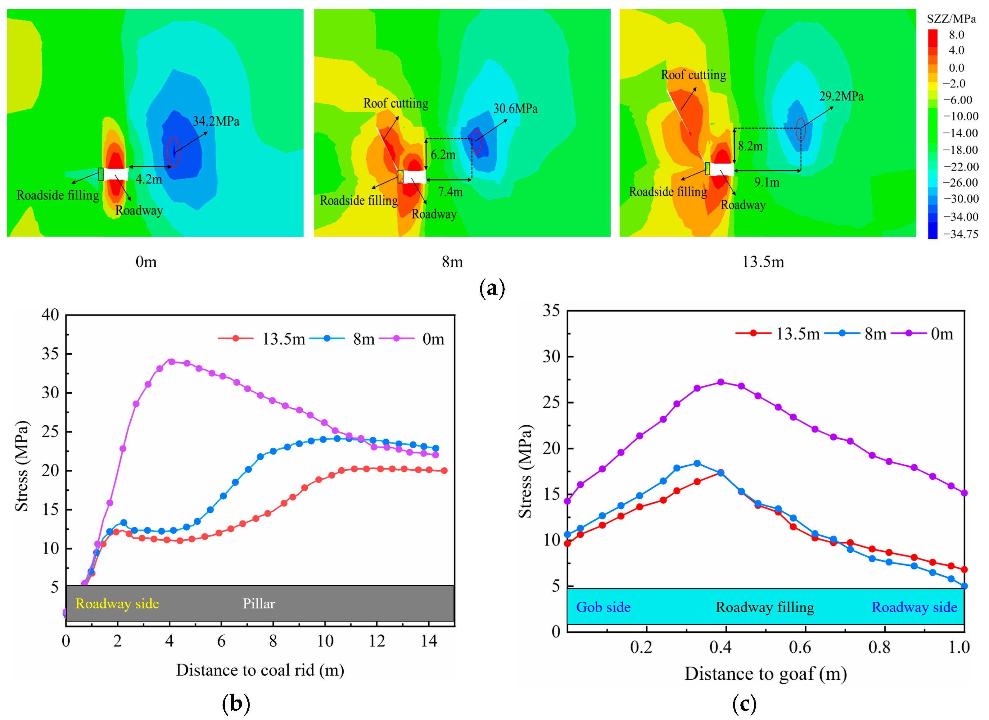
To verify the effectiveness of the synergistic effect between roof cutting and roadside filling, the stress distribution characteristics of no roof cutting, 8 m roof cutting, and 13.5 m roof cutting were analyzed. The stress image is shown in Figure 12a. In addition, the stress distribution on the solid coal side of the roadway is shown in Figure 12b. The comprehensive analysis reveals that: under the conditions of no roof cutting, the stress concentration on the solid coal side reaches a peak of 34.2 MPa, and the peak area is only 4.2 m away from the coal side. The stress showed a trend of rapidly increasing and then gradually decreasing, eventually reaching a stable state. In contrast, under roof cutting conditions, the range of the stress concentration zone decreases and moves away from the roadway. When the roof cutting height was 8 m, the peak stress drops to 30.6 MPa, and the peak area was 7.4 m away from the solid coal wall and 6.2 m above the roadway. When the roof cutting height increases to 13.5 m, the peak stress continued to decrease to 29.2 MPa, and the peak area was 9.1 m away from the solid coal wall and 8.2 m above the roadway. After roof cutting, the stress shows a slow increase process, and is far from the stress peak, indicating that the stress of the solid coal support is reduced after roof cutting, causing stress redistribution. With an increase in the roof cutting depth, the roadway stress environment can be further optimized, and the stress concentration zone can be transferred to the deep coal body. Figure 12c shows the stress of the roadside filling body at different roof cutting heights. When the roof is not cut, the filling body is subjected to a large force, with a maximum peak value of 26.6 MPa. After roof cutting, the stress peak at a depth of 8 m and 13.5 m decreases to 17.8 MPa and 16.3 MPa, respectively, with a decrease of 33.1% and 38.7%, respectively, indicating that the long cantilever beam is cut during roof cutting, which can effectively reduce the stress borne by the filling body, reducing the stress transmitted to the floor and reducing the amount of roadway floor heave.
It can be seen from the above analysis that the greater the roof cutting depth, the better the pressure relief effect; however, as the depth increased, the pressure relief efficiency gradually decreased. Therefore, it is necessary to determine the roof cutting depth based on actual conditions, construction volume, and cost.

5. Engineering Application

5.1. Scheme Design

5.1.1. Roof Cutting Design

The collapsed rock layers within the roof cutting height can fill the entire goaf by determining a reasonable roof cutting depth and cutting length for the roof cantilever beam, thereby providing better support for the higher rock layers, optimizing the roadway retaining roof structure, minimizing the disturbance caused by the rotary subsidence of the roof rock layers, improving the surrounding rock stress of the gob-side roadway retention, and enhancing its stability. The depth of the roof cutting boreholes is related to the mining height, roof subsidence, and floor heave, and is mainly determined by the following calculation methods:
H f = M Δ H 1 Δ H 2 / k 1
where M is the mining height, m; Δ H 1 is the roof subsidence, m; Δ H 2 is the floor heave, m; k is the coefficient of fragmentation and expansion, 1.2~1.5.
Based on the lithology of the roof, the conservative value of k = 1.2 is taken. Without considering the floor heave and roof subsidence, the average mining height of the working face was taken as 2.6 m, obtaining a vertical roof cutting height of 13 m. As the blast hole needs to be inclined towards the goaf by 15°, the depth of the directional blast hole is designed to be 13.5 m, which is consistent with the key parameter research results of the numerical simulation. In order to ensure the formation of penetrating cracks after blasting, the spacing between the roof cutting holes is determined to be 0.6 m based on theoretical calculations and peeping results after field tests. The final key roof cutting parameters were designed as follows: the diameter of the blast hole was 52 mm; the spacing was 0.6 m; the angle with the vertical direction was 15°; and the depth was 13.5 m.
The explosive loading parameters of the blast hole are designed to be 9 m for explosive loading and 4.5 m for hole sealing. Three bidirectional energy gathering tubes with a diameter of 42 mm and length of 3 m were placed in each blast hole. The explosive used is a Grade III emulsion explosive for coal mines, with a charge specification of φ35 mm × 300 mm/roll. A blast hole was drilled using a rig. Two lead wires were installed inside each blast hole and connected in series. Two energy gathering tubes were connected by specialized connectors to guarantee a consistent direction of the energy gathering holes inside the tubes, ensuring the consistency of the direction of pre-splitting blasting. Additionally, the blast hole is filled with stemming to seal the hole, prevent the energy gathering tube from slipping out, and ensure the quality of the blasting. The scheme design and explosive loading structure are shown in Figure 13.

5.1.2. Support Design

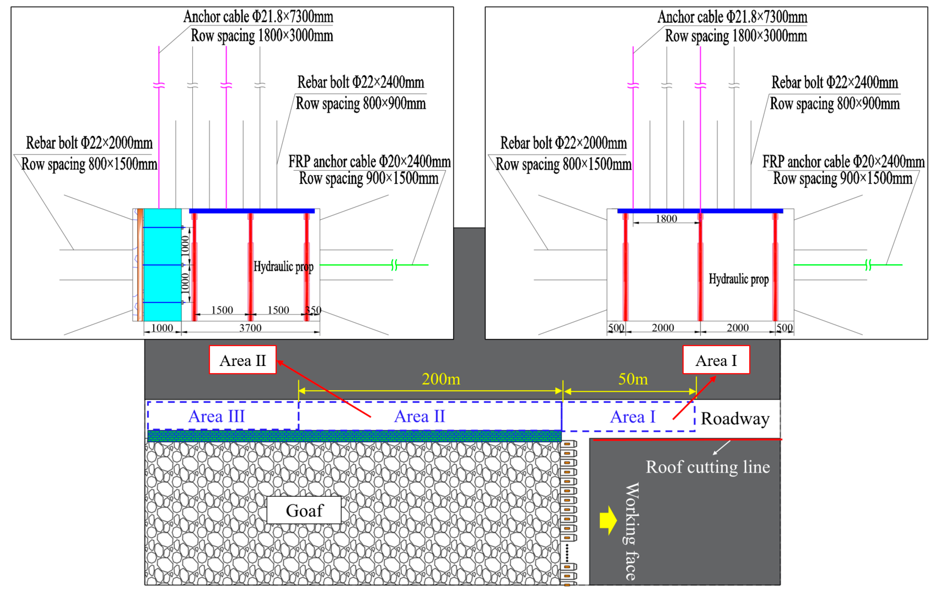
Based on the original composition, the roadway surrounding rock support was equipped with two rows of reinforced anchor cables (with a diameter of 21.6 mm and a length of 7300 mm) vertically arranged on the roadway roof. The first row was arranged 700 mm away from the mining side, and the second row was arranged at the center of the roadway with a spacing of 1800 × 3000 mm. A row of fiberglass reinforced anchor cables with a spacing of 3000 mm and length of 5500 mm were arranged in the middle of the non-mining side. The pre-tightening force of the roof anchor cable should be ≥180 kN, and the exposed area should be controlled within the range of 150–250 mm. The roadway support design mainly includes filling support design and temporary support design, as shown in Figure 14. Filling support design: After mining the working face, a flexible formwork concrete wall is poured on the roadway goaf side following the support of the working face to suppress roof subsidence and gangue outburst. The width of the concrete wall was 1000 mm with a filling length of 3 m each, and the concrete strength was C30. Anchor bolts were pre-installed in the concrete wall, with a specification and model of Φ22 × 1200 mm thread steel. The spacing between the split bolts is 1000 × 800 mm, and the thread length at both ends was 100 mm. The size of the support plate is 150 × 150 × 10 mm. Double support plates and nuts were used. The pre-tightening torque of the anchor bolt is 150 N·m. Temporary support design: this part adopts a segmented support and is divided into three zones. Among them, the 50 m range of the advanced working face (Zone I) is the advanced stress influence zone, which is mainly affected by advanced mining stress; it is supported by single hydraulic supports with π-shaped beams, with 3 single supports per row, a spacing of 2000 mm × 1000 mm between rows, and a length of the π-shaped beam of 4500 mm; the 200 m range of the lagging working face (Zone II) is the dynamic pressure influence zone, which is mainly affected by the dynamic pressure of the collapsed gangue in the goaf, and supported by single hydraulic supports with π-shaped beams, with 3 single supports per row, a spacing of 1500 mm × 1000 mm between rows, and the length of the π-shaped beam of 3500 mm; and the zone beyond 200 m of the lagging working face (Zone III) is a stable mining pressure zone, where the goaf tends to stabilize and the roadway is less affected by mining. Based on the mining pressure monitoring results, single pillars and π-shaped beams could be gradually removed.

5.2. Analysis of Application Effects

5.2.1. Monitoring Scheme

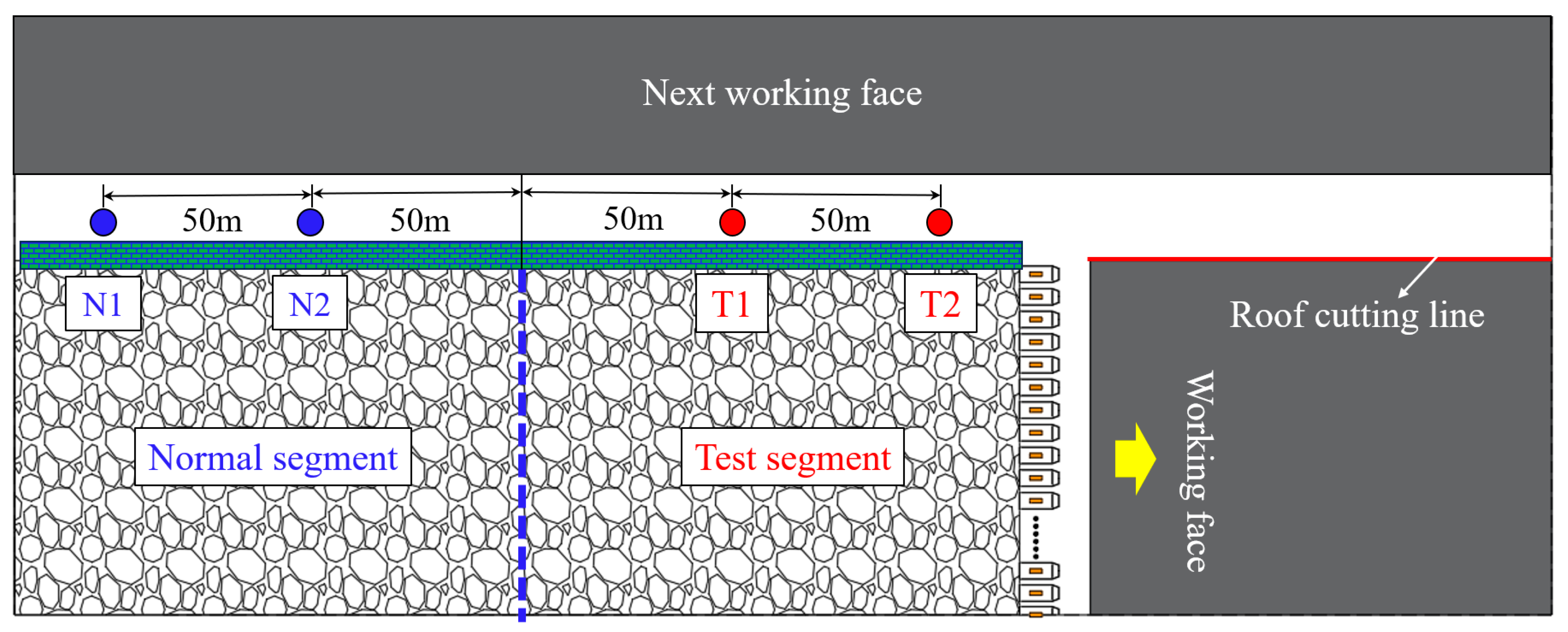
In the field tests, the normal section uses gob-side roadway retention through roadside filling, while the test section uses gob-side roadway retention through roadside filling and roof cutting. To verify the effectiveness of gob-side roadway retention through roadside filling and roof cutting technology, a comparative analysis was conducted on the application effects of gob-side roadway retention through roadside filling technology and gob-side roadway retaining through roadside filling and roof cutting technology. Comparative monitoring was conducted on the stress of hydraulic prop in the advanced stress influence zone, the stress of the filling body in the dynamic pressure influence zone, and the deformation of the surrounding rock in the roadway retained in the normal and test sections. The monitoring scheme and station layout are shown in Figure 15.

5.2.2. Hydraulic Prop Stress

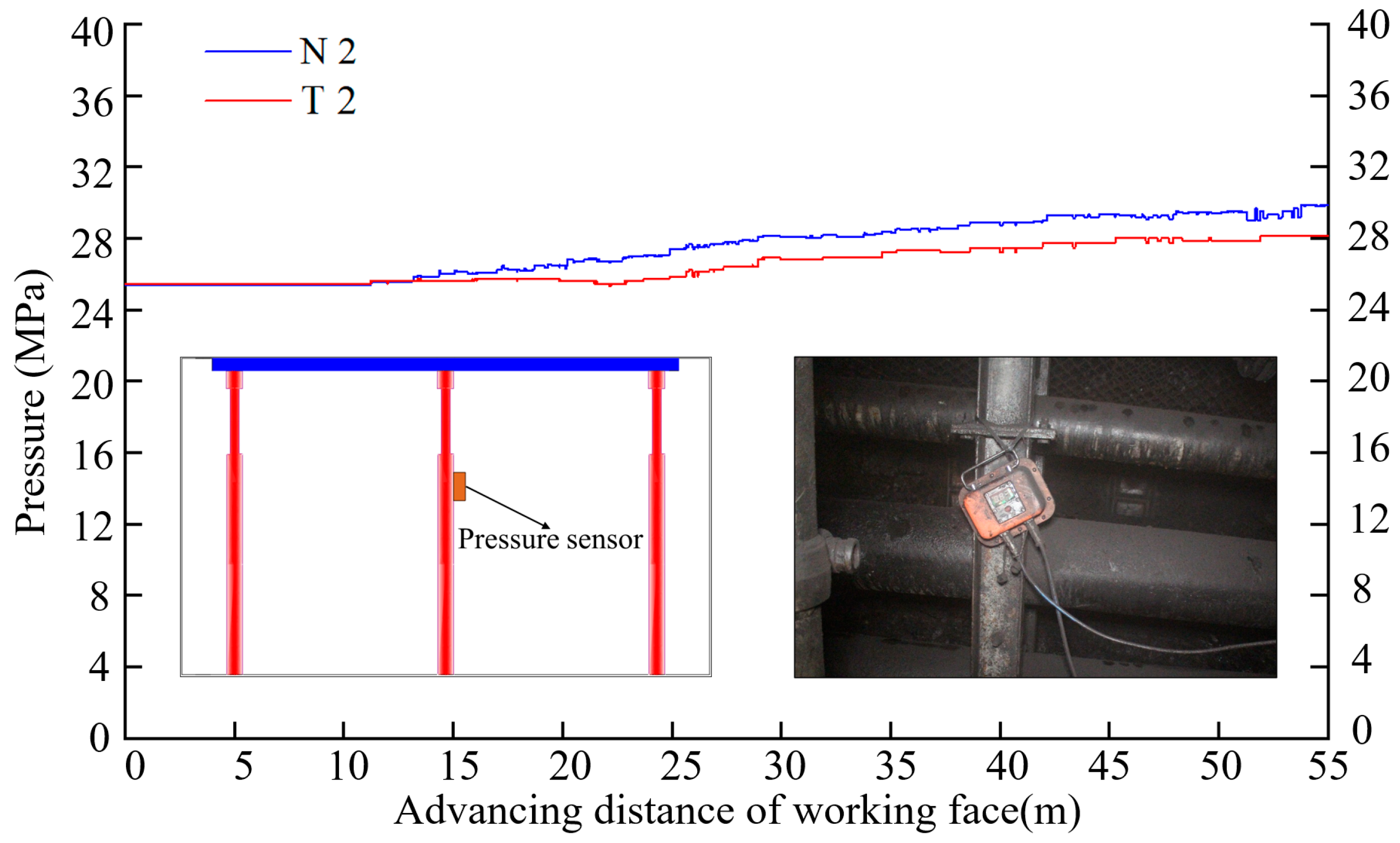
As core equipment for underground support in coal mines, hydraulic props can effectively support roadway roofs. Monitoring the pressure changes in single pillars can truly reflect the subsidence of the overburden layer in the retained roadway, thereby evaluating the roadway retaining effects. The monitoring data of N2 monitoring station in the normal section and T2 monitoring station in the test section in Figure 15 were selected for comparative analysis. When the working face advanced from the 55 m position in front of the monitoring station, the measuring unit recorded the pressure change in the hydraulic props separately, as shown in Figure 16. As shown in the figure in the normal section, when the working face was 40 m away from the monitoring station, the pressure of the hydraulic prop began to significantly increase. In the test section, when the working face was 26 m away from the monitoring station, the pressure of the hydraulic prop began to significantly increase. Compared with the normal section, the pressure increase position of the test section is closer to the monitoring station, and the peak pressure value has decreased from 30.8 MPa in the normal section to 28.2 MPa, with a decrease of 8.5%. Thus, roof cutting and pressure relief can reduce the influence range of advanced mining pressure on the working face, and the stress on the roadway roof, thereby protecting the stability of the roadway roof.

5.2.3. Filling Body Stress

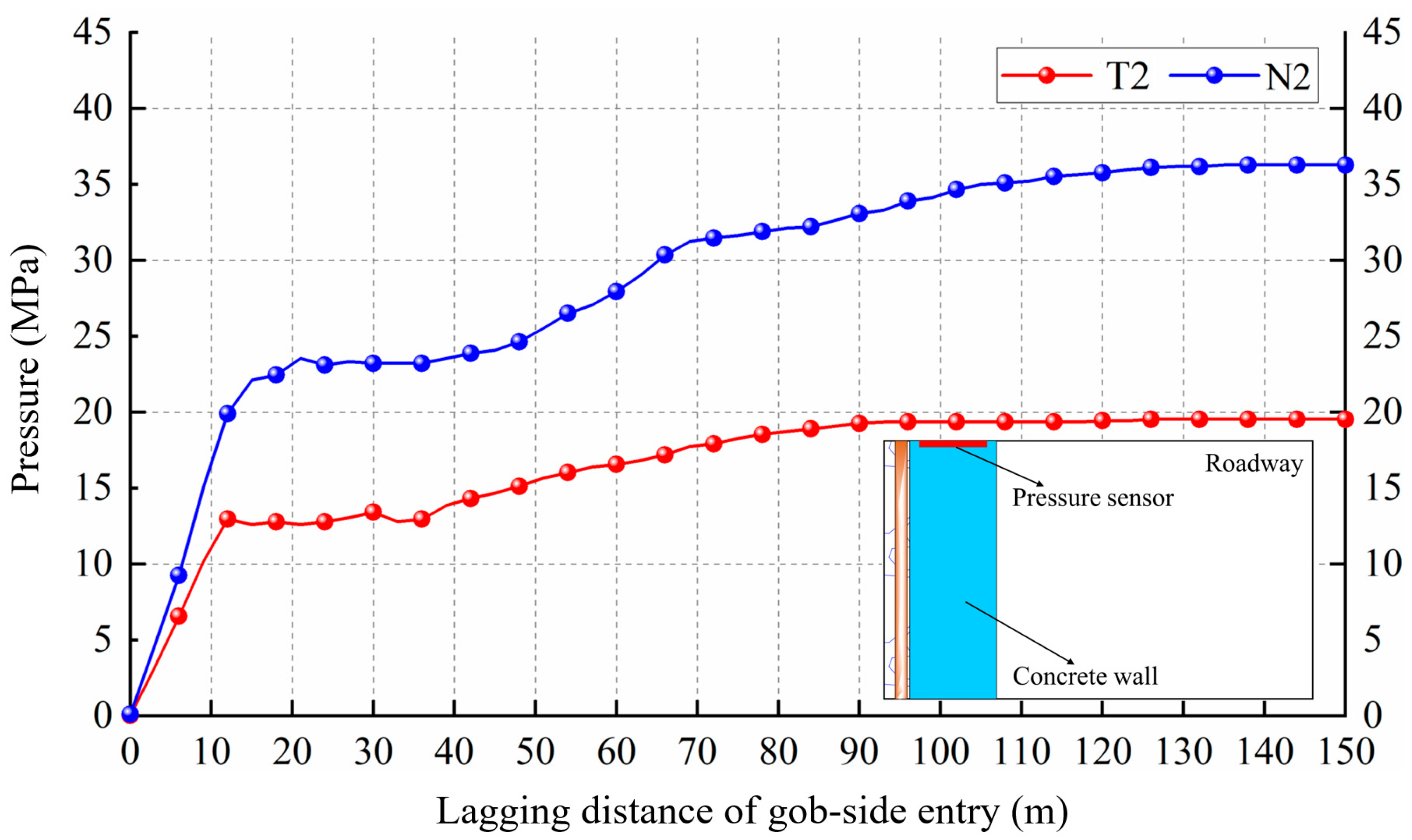
In the entire roadway retaining process, the filling body is crucial for the stability of the roadway, as it can suppress roof subsidence and prevent the influx of gangue into the roadway. Monitoring the pressure of the filling body can effectively reflect the roof pressure and verify the pressure relief effect of roof cutting. The monitoring data of N2 monitoring station in the normal section and T2 monitoring station in the test section within 150 m of the lagging working face shown in Figure 15 were selected. The monitoring curves are shown in Figure 17. It can be seen from the figure that in the normal section, when the lagging working face is 21 m, the pressure rapidly increases to 23.5 MPa and then remains relatively unchanged. When the lagging working face reached 45 m, the pressure continued to increase rapidly, and tended to stabilize until the lagging working face reached 120 m. In the test section, when the lagging working face was 12 m, the pressure rapidly increases to 13.6 MPa and then remained relatively constant. When the lagging working face was 35 m, the pressure continued to slowly increase, and tended to stabilize until the lagging working face reached 90 m. It can be seen that the adoption of the gob-side roadway retaining through roadside filling and roof cutting reduces the range of the dynamic pressure influence zone of the lagging working face, and the amplitude of pressure fluctuations, and weakens the influence of the dynamic pressure of the goaf on the retained roadway. In addition, the peak pressure of the filling body in the test section decreases significantly, from 36.2 MPa in the normal section to 19.5 MPa, with a decrease of 46.1%, which is mainly because the directional blasting cuts off the cantilever beam, causing sufficient collapse of the goaf, and supporting the overburden layers. Therefore, the monitoring data indicate that the roof cutting and pressure relief effects are significant in optimizing the stress environment of the roadway.

5.2.4. Roadway Surrounding Rock Deformation

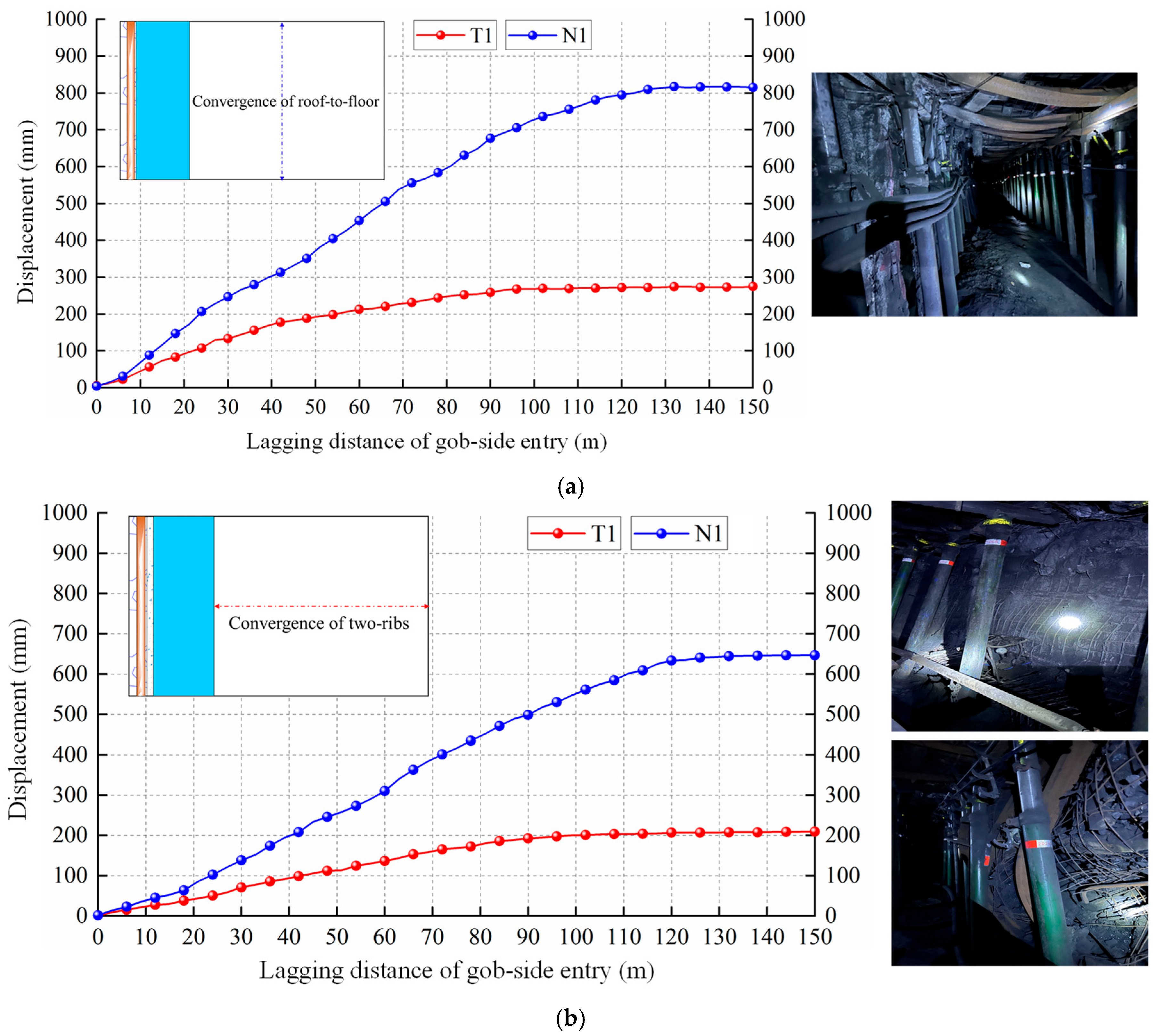
The convergence of the roadway section is a direct reflection of the surrounding rock stress, which can objectively evaluate the roadway retaining effects and reflect the effectiveness of the gob-side roadway retaining technology. A comparative analysis was conducted on the convergence of the roof and floor with the surrounding rock of the two sides at N1 monitoring station in the normal section and T1 monitoring station in the test section, as shown in Figure 18. After the working face was mined, the cross point method was used to record the displacement of the roadway section. In the normal section, the convergence deformation rate of the surrounding rock is relatively high, with a peak convergence of 830 mm for the roof and floor, and 659 mm for both sides. In addition, field observations showed that the surrounding rock deformation in certain areas is particularly severe, and the filling body is tilted or even damaged. In the test section, the convergence deformation rate of the surrounding rock significantly decreased, with a peak convergence of 286 mm for the roof and floor (a decrease of 65.4% compared to the normal section) and 220 mm for both sides (a decrease of 66.6% compared to the normal section). In addition, the convergence of the roadway surrounding rock in the normal section gradually tends to stabilize 130 m away from the lagging working face, while that in the test section tends to stabilize 100 m away from the lagging working face. Therefore, the dynamic pressure influenced the distance of the roadway decreased from 130 m in the normal section to 100 m in the test section, with a decrease of 16.6%. The roadway surrounding rock deformation monitoring data indicate that compared with the gob-side roadway retaining through roadside filling technology, the gob-side roadway retaining through gob-side filling and roof cutting technology significantly reduces the roadway surrounding rock deformation and the dynamic pressure influence zone, achieving a good roadway retaining effect.

6. Discussion

This chapter systematically analyzes the control effect and key parameters of the gob-side roadway retention through roadside filling and roof cutting technology through a combination of numerical simulations and field tests. The study demonstrates that this method effectively blocks the stress transfer path from the goaf by cutting off the long cantilever roof structure, significantly reduces stress concentration in the surrounding rock, and improves the distribution of deformation and plastic zones. Numerical simulation results indicate that the cut-off technique reduces the peak stress on the solid coal side by 10.5%, shifts the peak stress location outward by 76.1%, decreases floor deformation by 50.2%, reduces roof deformation by 30%, and markedly shrinks the plastic zone of the surrounding rock. Field tests further confirm the practical effectiveness of the technology: the peak pressure on hydraulic supports decreases by 8.5%, the peak stress on the backfill body drops by 46.1%, the convergence of the surrounding rock is reduced by over 65%, and the influence range of dynamic pressure is narrowed by 16.6%. Overall, the gob-side roadway retention through roadside filling and roof cutting technology demonstrates significant technical advantages and application potential under complex geological conditions. Future research may focus on further optimizing the synergistic design of roof cutting and backfill, as well as extending its applicability to a wider range of geological conditions.

7. Conclusions

In this study, to realize non-coal pillar mining under deep high-stress environment and hard roof conditions, a new method of gob-side roadway retention through roadside filling and roof cutting is proposed, which consists of two key technologies: flexible formwork filling, and roof cutting and pressure relief. The former mainly plays the role of strong support, whereas the latter plays the role of stress release. By combining the advantages of the two technologies, a pressure relief-support dynamic balance system is formed, achieving the goal of gob-side roadway retention under complex high-stress conditions.
To further explore the effectiveness of gob-side roadway retaining through roadside filling and roof cutting methods, numerical simulation models were established for gob-side roadway retention through roadside filling, and gob-side roadway retention through roadside filling and roof cutting, and a comparative analysis was conducted on the roadway retention effects of the two methods. The research results show that the gob-side roadway retention through roadside filling and roof cutting technology significantly reduces the surrounding rock stress, optimizes the roadway stress environment, and reduces the surrounding rock deformation. In addition, numerical simulation models were established with different key parameters, and the optimal key parameters of the filling body were obtained through comparative analysis as follows: when the width was 1 m, C30 concrete was filled. Combined with field mining conditions and construction costs, the optimal key parameters for roof cutting and pressure relief are designed as follows: drilling depth of 13.5 m, and angle of 15° from the vertical direction.
Based on the above research, a scheme was designed for gob-side roadway retention through roadside filling and roof cutting method and applied to field projects. The field monitoring results show that the new methods controls the roof deformation under the strong support of the filling body, and cuts off the cantilever beam and stress transmission path using roof cutting and pressure relief technology, which reducing the stress and displacement of the roadway surrounding rock under the synergistic effect of strong support and stress release, realizing good roadway retaining effects, and achieving non-coal pillar mining under complex high-stress conditions. Furthermore, this method can be extended to complex conditions such as high mining height, rapid extraction, complex tectonic stresses, and high ground stress at great depths. It contributes to the efficient conservation of coal resources under such challenging conditions while ensuring safe and highly productive mining operations. As the technology continues to be adopted in the future, further research will be needed in two key areas: non-blast roof cutting techniques and cost control for gate road retention.

Author Contributions

Conceptualization, H.G., Y.L. and Y.S.; methodology, H.G., S.Z., Q.F. and K.L.; validation, H.G., K.L. and Y.S.; formal analysis, H.G., W.R., Y.L. and Z.Z.; resources, H.G., Y.L. and Q.F.; writing—original draft preparation, H.G.; writing—review and editing, H.G., Q.F. and Y.S.; supervision, H.G., S.Z. and Y.L.; project administration, H.G. and Y.L.; funding acquisition, S.Z., H.G. and Y.L. All authors have read and agreed to the published version of the manuscript.

Funding

This work is supported by National Natural Science Foundation of China (Grant No.52474230), Project supported by the National Key Research and Development Program of China (2024YFC2909500), the China Postdoctoral Science Foundation-CCTEG Joint Support Program (Grant No.2025T043ZGMK), the Science and Technology Development Fund Project of China Coal Research Institute (Grant No.2024QN-06), and the Science and Technology Innovation Fund of TianDi Science and Technology Co., Ltd. (Grant No. 2023-TD-ZD001-004 and 2024-TD-ZD010-01), which are gratefully acknowledged.

Institutional Review Board Statement

Not applicable.

Informed Consent Statement

Not applicable.

Data Availability Statement

The original contributions presented in this study are included in the article. Further inquiries can be directed to the corresponding authors.

Conflicts of Interest

The authors declare no conflicts of interest.

References

  1. Wang, J.L.; Feng, L.Y.; Davidsson, S.; Hook, M. Chinese coal supply and future production outlooks. Energy 2013, 60, 204–214. [Google Scholar] [CrossRef]
  2. Xue, G.; Yilmaz, E.; Feng, G.; Cao, S. Analysis of tensile mechanical characteristics of fibre reinforced backfill through splitting tensile and three-point bending tests. Int. J. Min. Reclam. Environ. 2022, 36, 218–234. [Google Scholar] [CrossRef]
  3. Akinbinu, V.A. Relationship of brittleness and fragmentation in brittle compression. Eng. Geol. 2017, 221, 82–90. [Google Scholar] [CrossRef]
  4. Chen, S.M.; Wu, A.X.; Wang, Y.M.; Chen, X.; Yan, R.F.; Ma, H.J. Study on repair control technology of soft surrounding rock roadway and its application. Eng. Fail. Anal. 2018, 92, 443–455. [Google Scholar] [CrossRef]
  5. Zhang, C.L.; Wang, P.Z.; Wang, E.Y.; Chen, D.P.; Li, C. Characteristics of coal resources in China and statistical analysis and preventive measures for coal mine accidents. Int. J. Coal Sci. Techn. 2023, 10, 1–16. [Google Scholar] [CrossRef]
  6. Afrouz, A.; Hassani, F.P.; Scoble, M.J. Geotechnical assessment of the bearing capacity of coal mine floors. Int. J. Mining Geol. Eng. 1988, 6, 297–312. [Google Scholar] [CrossRef]
  7. Sun, X.M.; Jiang, M.; Zhang, T.; Miao, C.Y. A novel method of deep and shallow combined roof cutting and constant resistance support for enhancing deep mining roadway stability. Min. Metall. Explor. 2025, 42, 1421–1440. [Google Scholar] [CrossRef]
  8. Yuriy, G.; Vayenas, N. Discrete-event simulation of mine equipment systems combined with a reliability assessment model based on genetic algorithms. Int. J. Min. Reclam. Environ. 2008, 22, 70–83. [Google Scholar] [CrossRef]
  9. Khandelwal, M.; Faradonbeh, R.S.; Monjezi, M.; Armaghani, D.J.; Yagiz, S. Function development for appraising brittleness of intact rocks using genetic programming and nonlinear multiple regression models. Eng. Comput. 2016, 32, 13–21. [Google Scholar] [CrossRef]
  10. Jiang, L.S.; Wu, Q.S.; Wu, Q.L.; Wang, P.; Xue, Y.C.; Kong, P.; Gong, B. Fracture failure analysis of hard and thick key layer and its dynamic response characteristics. Eng. Fail. Anal. 2019, 98, 118–130. [Google Scholar] [CrossRef]
  11. Shabanimashcool, M.; Li, C.C. A numerical study of stress changes in barrier pillars and a border area in a longwall coal mine. Int. J. Coal Geol. 2013, 106, 39–47. [Google Scholar] [CrossRef]
  12. Wang, H.W.; Wang, Y.P.; Jiang, J.Q.; Chen, P.P. Stability mechanism and control technology for fully mechanized caving mining of steeply inclined extra-thick seams with variable angles. Min. Metall. Explor. 2021, 38, 1047–1057. [Google Scholar]
  13. Ozfirat, M.K.; Yenice, H.; Simir, F.; Yarali, O. A new approach to rock brittleness and its usability at prediction of drillability. J. Afr. Earth. Sci. 2016, 119, 94–101. [Google Scholar] [CrossRef]
  14. Xie, P.; Luo, Y.; Wu, Y.; Gao, X.; Luo, S.; Zeng, Y. Roof deformation associated with mining of two panels in steeply dipping coal seam using subsurface subsidence prediction model and physical simulation experiment. Min. Metall. Explor. 2020, 37, 581–591. [Google Scholar] [CrossRef]
  15. Li, T.; Chen, G.B.; Qin, Z.C.; Li, Q.H.; Cao, B.; Liu, Y.L. The gob-side entry retaining with the high-water filling material in Xin’an Coal Mine. Geomech. Eng. 2020, 22, 541–552. [Google Scholar]
  16. Kang, Y.S.; Liu, Q.S.; Xi, H.L.; Gong, G.Q. Improved compound support system for coal mine tunnels in densely faulted zones: A case study of China’s Huainan coal field. Eng. Geol. 2018, 240, 10–20. [Google Scholar] [CrossRef]
  17. Liu, X.S.; Ning, J.G.; Tan, Y.L.; Xu, Q.; Fan, D.Y. Coordinated supporting method of gob-side entry retaining in coal mines and a case study with hard roof. Geomech. Eng. 2018, 15, 1173–1182. [Google Scholar]
  18. Wang, J.; Liu, P.; He, M.C.; Yu, G.Y.; Tian, H.Z. Floor heave mechanism for gob-side entry retaining with concrete blocks and control method: A case study. Undergr. Space 2024, 15, 244–259. [Google Scholar] [CrossRef]
  19. Wang, H.; Jiang, C.; Zheng, P.Q.; Li, N.; Zhan, Y.B. Deformation and failure mechanism of surrounding rocks in crossed-roadway and its support strategy. Eng. Fail. Anal. 2020, 116, 104743. [Google Scholar] [CrossRef]
  20. Deng, G.Z.; Li, H.J. Study on the technology and application of cooperative roadway protection with roof cutting pressure relief and CO2 mineralization and filling. Sci. Rep. 2025, 15, 1–14. [Google Scholar] [CrossRef] [PubMed]
  21. Pu, S.J.; Wu, G.Y.; Liu, Q.Z.; Wang, Y.L.; Li, Q.; Xiong, Y. Determination of reasonable width of filling body for gob-side entry retaining in mining face with large cutting height. Geofluids 2022, 2022, 1–12. [Google Scholar] [CrossRef]
  22. Zhu, Y.H.; Tian, Y.; Gong, P.L.; Wen, G.; Yi, K. Predictive model for the instability of flexible formwork concrete wall in secondary mining of non-pillar coal mining. Sci. Rep. 2024, 14, 1–17. [Google Scholar] [CrossRef]
  23. Wang, Q.; Jiang, Z.H.; Jiang, B.; He, M.C.; Yang, J.; Xue, H.J. Ground control method of using roof cutting pressure release and energy-absorbing reinforcement for roadway with extra-thick hard roof. Rock Mech. Rock Eng. 2023, 56, 7197–7215. [Google Scholar] [CrossRef]
  24. Gao, Y.B.; Gai, Q.K.; Zhang, K.D.; Fu, Q.; Zhang, X.X. Strata behaviour and stability control of the automatic roadway formation by roof cutting below a fault influenced longwall goaf. Sci. Rep. 2022, 12, 1–18. [Google Scholar] [CrossRef]
  25. Yang, J.; He, M.C.; Cao, C. Design principles and key technologies of gob side entry retaining by roof pre-fracturing. Tunn. Undergr. Space Tech. 2019, 90, 309–318. [Google Scholar] [CrossRef]
  26. Wang, Y.J.; He, M.C.; Yang, J.; Wang, Q.; Liu, J.N.; Tian, X.C.; Gao, Y.B. Case study on pressure-relief mining technology without advance tunneling and coal pillars in longwall mining. Tunn. Undergr. Space Tech. 2020, 97, 103236. [Google Scholar] [CrossRef]
  27. Du, Z.W.; Chen, S.J.; Ma, J.B.; Guo, Z.P.; Yin, D.W. Gob-side entry retaining involving bag filling material for support wall construction. Sustainability 2020, 12, 6681. [Google Scholar] [CrossRef]
  28. Yang, J.; Fu, Q.; Gao, Y.B.; Wu, X.; Chang, X.; Li, C.J. A novel method of combined deep hole blasting for gob-side roadway protection. Rock Mech. Rock Eng. 2023, 56, 3551–3571. [Google Scholar] [CrossRef]
  29. Chen, D.C.; Wang, X.Y.; Wu, S.; Zhang, F.T.; Fan, Z.Z.; Wang, X.D.; Li, M.L. Study on stability mechanism and control techniques of surrounding rock in gob-side entry retaining with flexible formwork concrete wall. J. Cent. South Univ. 2023, 30, 2966–2982. [Google Scholar] [CrossRef]
  30. Xie, S.R.; Pan, H.; Chen, D.D.; Zeng, J.C.; Song, H.Z.; Cheng, Q.; Xiao, H.B.; Yan, Z.Q.; Li, Y.H. Stability analysis of integral load-bearing structure of surrounding rock of gob-side entry retention with flexible concrete formwork. Tunn. Undergr. Space Tech. 2020, 103, 103464. [Google Scholar] [CrossRef]
  31. Gao, Y.B.; Wang, Y.J.; Yang, J.; Zhang, X.Y.; He, M.C. Meso- and macroeffects of roof split blasting on the stability of gateroad surroundings in an innovative nonpillar mining method. Tunn. Undergr. Space Tech. 2019, 90, 99–118. [Google Scholar] [CrossRef]
  32. Fu, Q.; Yang, J.; Song, H.X.; Wu, X.; Liu, Y.X.; Wei, X.J. Study on the method of pressure relief and energy absorption for protecting roadway under thick and hard roof. Rock Mech. Rock Eng. 2023, 56, 7177–7196. [Google Scholar] [CrossRef]
  33. Wang, Y.J.; Gao, Y.B.; Wang, E.Y.; He, M.C.; Yang, J. Roof deformation characteristics and preventive techniques using a novel non-pillar mining method of gob-side entry retaining by roof cutting. Energies 2018, 11, 627. [Google Scholar] [CrossRef]
Figure 1. Working face overview and field failure condition.
Applsci 15 10119 g001
Figure 2. Roadside filling technology.
Applsci 15 10119 g002
Figure 3. Roof cutting and pressure relief technology.
Applsci 15 10119 g003
Figure 4. Synergistic control method.
Applsci 15 10119 g004
Figure 5. Mechanical model of roof structure. (a) Gob-side roadway retaining through roadside filling; (b) Gob-side roadway retaining through roadside filling and roof cutting. a: Retained roadway width, m; b1,2: Roof stratum thickness, m; L1,2: Roof stratum length, m; l: Filling body width, m; θ1,2: Rotation angle of fractured rock block, °; pz: Support intensity of anchor cables, MPa; pl: Support intensity of filling body, MPa; l0: Overhanging length of roof in goaf, m.
Applsci 15 10119 g005
Figure 6. Overburden strata movement model. (a) Gob-side roadway retaining through roadside filling; (b) Gob-side roadway retaining through roadside filling and roof cutting.
Applsci 15 10119 g006
Figure 7. Numerical simulation model.
Applsci 15 10119 g007
Figure 8. Distribution of stresses in the roadway influence zone. (a) Roadside filling; (b) Roadside filling and roof cutting.
Applsci 15 10119 g008
Figure 9. Spatial distribution of deformation processes in the roadway area. (a) Roadside filling; (b) Roadside filling and roof cutting.
Applsci 15 10119 g009
Figure 10. Surrounding rock plastic zone comparison. (a) Roadside filling; (b) Roadside filling and roof cutting.
Applsci 15 10119 g010
Figure 11. Comparative analysis of filling bodies with different widths. (a) Filling body stress distribution; (b) Peak stress and damage rate of filling body.
Applsci 15 10119 g011
Figure 12. Comparative analysis of roof cutting depth effects. (a) Stress image for various roof cutting heights; (b) Stress evolution in solid coal; (c) Stress distribution within filling body.
Applsci 15 10119 g012
Figure 13. Roof cutting design diagram.
Applsci 15 10119 g013
Figure 14. Support design scheme.
Applsci 15 10119 g014
Figure 15. Monitoring scheme design.
Applsci 15 10119 g015
Figure 16. Hydraulic prop pressure monitoring.
Applsci 15 10119 g016
Figure 17. Filling body pressure monitoring.
Applsci 15 10119 g017
Figure 18. Roadway surrounding rock deformation monitoring. (a) Convergence of roof-to-floor; (b) Convergence of two ribs.
Applsci 15 10119 g018
Table 1. Roof subsidence sensitivity factors.
Parameter ValuesSensitivity Coefficient
Rotation angle θθ = 1.5°~5.0°5.689~9.887
Roof length LL = 4.7~7.5 m38.659~12.563
Roof thickness bb = 10~14 m1.589~2.697
Table 2. Mechanical parameters of rock block.
LithologyDensity (kg/m3)Bulk Modulus
/GPa
Shear Modulus
/GPa
Cohesion
/MPa
Tensile Strength
/MPa
Friction Angle
/(°)
Overlying rock strata250012.99.61.51.4130
Fine-grained sandstone25607.45.41.80.7930
Limestone236010.23.91.51.4130
Siltstone18905.24.21.50.8924
Coal24305.044.12.30.426
Roadside filling230010.56.23.21.534
Disclaimer/Publisher’s Note: The statements, opinions and data contained in all publications are solely those of the individual author(s) and contributor(s) and not of MDPI and/or the editor(s). MDPI and/or the editor(s) disclaim responsibility for any injury to people or property resulting from any ideas, methods, instructions or products referred to in the content.