1. Introduction
The development of the aerospace industry is one of the important influencing factors of China’s comprehensive strength. However, due to the high cost of spacecraft design, manufacturing, testing, launch, and in orbit operation and management, the reliability and long-term effectiveness of spacecraft are crucial. Due to extreme conditions such as vacuums, weightlessness, and large temperature changes in the space environment [
1,
2,
3], lubricant evaporation and lubricant film rupture can easily occur. Friction and wear of mechanical operating components caused by lubrication failure are important factors leading to spacecraft failures [
4,
5,
6]. Therefore, high requirements are placed on space lubrication technology for spacecraft. Space lubrication technology is mainly divided into passive lubrication technology and active lubrication technology. Passive lubrication technology mainly relies on the centrifugal force or surface migration force generated during shaft rotation to lubricate bearing rollers, including centrifugal lubricators [
7], exudative lubricators [
8], oil rope supply technology [
9], and porous lubrication technology [
10,
11,
12]. Passive lubrication has poor controllability and adaptability in terms of oil supply, and is greatly affected by structural speed. The amount, time, and position of oil replenishment cannot be controlled in real time. Active lubrication technology involves the lubrication of bearing rollers through instructions issued by the control unit, mainly including static oil-storage technology [
13], electromagnetic lubrication technology [
14], and piezoelectric lubrication technology [
15]. At present, the main challenge faced by active lubrication technology is that the single oil supply is too large, and excessive lubrication can easily cause a nonlinear increase in bearing friction torque, leading to the abnormal wear or failure of mechanical moving parts due to a sudden increase in friction power consumption. Therefore, the traditional active fuel-supply scheme can no longer meet the requirements, and the long-term lubrication problem in space has become the main reason limiting the lifespan of spacecraft. Therefore, it is necessary to timely and appropriately replenish lubricating oil during the operation of spacecraft in orbit to ensure the service life of the spacecraft.
Piezoelectric driving is a new driving technology that utilizes the inverse piezoelectric effect of piezoelectric materials to convert electrical energy into mechanical motion output. It has advantages such as high resolution, fast response speed, resistance to electromagnetic interference, and power-off self-locking [
16,
17]. Domestic and foreign scholars have conducted extensive research in the field of piezoelectric micro fuel supply technology and made significant progress. In terms of device design and oil-supply performance, the piezoelectric micro-spray device designed by Li Wangxin et al. [
18] achieved precise injection with a single oil supply as low as 6 × 10
−6 mL through precise driving control, providing an effective solution for micro upgrading lubrication; the ultrasonic atomizer developed by Axel Lefebure and Dong haShim [
19] utilizes the piezoelectric effect to achieve a stable atomization output of up to 13.4 mL/h in continuous-operation mode, which is suitable for scenarios requiring high flow rates; the threaded piezoelectric actuator proposed by Sun Jianhua et al. [
20] achieved a controllable droplet ejection of a single pulse of 6 × 10
−5 mL in pulse mode. In researching piezoelectric drive and vibration characteristics, Zhang Xuhui [
21] designed a magnetic coupled-array piezoelectric energy harvester and simulated and analyzed the influence of excitation amplitude and frequency on system response; Pan Qiaosheng [
22] proposed a cross-band piezoelectric screw motor that can operate simultaneously in static, quasi-static, and resonant states, and determined that different motors can exhibit different motion characteristics at different operating frequencies; Wang Xinjie [
23] proposed a bidirectional self-propelled linear piezoelectric microactuator, which generates an elliptical motion trajectory at the driving foot by superimposing two bending vibration modes. The relationship between the displacement of the driving foot and frequency was revealed through modal simulation and transient simulation. Ki Woong Seong [
24] developed an ultrasonic hearing-aid receiver that measures the sound-pressure distribution at different frequencies using a laser vibrometer and a tube microphone. The experimental results show that compared to traditional BA receivers, the ultrasonic parameter receiver provides higher sound-pressure output at frequencies of 5 kHz and above.
Although the above research has achieved important results, the further application of piezoelectric micro oil-supply technology in the special scenario of the ultra-precision lubrication of spacecraft still faces two key challenges: firstly, the single oil supply of existing devices is generally too large, which makes it difficult to meet the strict requirements of ultra-micro lubrication for key components of spacecraft; secondly, the research on the regulation mechanism between vibration characteristics and fuel supply is not yet comprehensive, which restricts the further improvement of fuel-supply accuracy. In view of the shortcomings of the current technology in terms of excessive single oil supply and insufficient precise dynamic regulation ability, especially the lack of understanding of the core correlation mechanism of “excitation-vibration-oil supply”, this paper proposes a new type of piezoelectric oil-supply device based on an array of metal sheets with groups of cone-shaped holes, which aims to solve the core problems of easy blockage and poor output stability in the traditional single-hole oil-supply scheme. Although the driving components of the device share similarities with the piezoelectric atomizer, the overall system has a completely new design and optimization for the specific application scenario of “directional micro-oil supply in a closed environment”, rather than simply using the atomizer structure. On this basis, the vibration characteristics of the device are analyzed in depth. The specific research content is as follows:
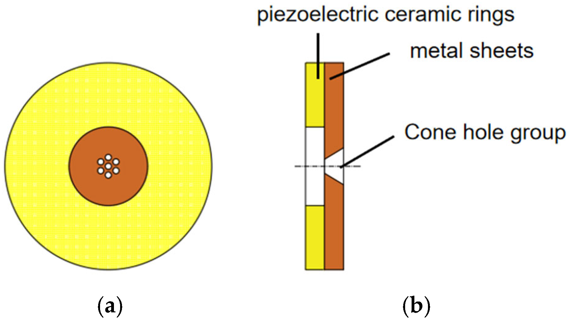
(1) Design a piezoelectric driving structure consisting of a piezoelectric ceramic ring and a metal sheet, with an array of tapered holes at the center of the metal sheet. When oil flows through a conical hole under vibration pressure, it is throttled by the contraction effect of the flow channel and distributed uniformly in an array, laying the foundation for micro oil supply structurally;
(2) Establish a finite-element model of the device, identify the vibration modes and natural frequencies corresponding to different orders through modal analysis, screen and determine the suitable working vibration modes and their corresponding frequencies based on the requirements of the fuel-supply scenario, and provide a reference for subsequent research on vibration characteristic;
(3) By using a finite-element simulation system to study the vibration characteristics of the device, the focus is placed on revealing the control laws of parameters such as excitation waveform, frequency, and amplitude on the displacement response amplitude and response period, in order to provide theoretical support for clarifying the inherent relationship between “excitation vibration fuel supply”.
3. Results and Discussion
3.1. Modal Analysis
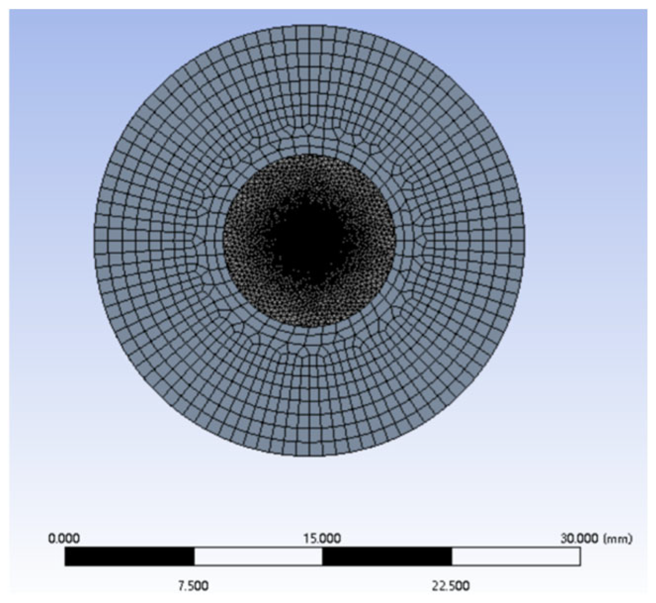
After the establishment of the finite-element model of the piezoelectric vibrator and the parameter setting, the modal analysis of the ring vibrator is carried out to obtain the natural frequency and vibration-mode characteristics of the structure, which lays a foundation for the subsequent study of its dynamic response characteristics. The working mechanism is that the axial displacement amplitude generated by the piezoelectric vibrator under excitation directly determines the volume-change rate of the cone cavity of the device. The larger the displacement amplitude is, the more significant the pressure-wave enhancement effect of the oil in the cone hole is, the higher the intensity of the formed pressure wave is, and the higher the efficiency of driving the oil injection is. However, the axial deformation characteristics of the piezoelectric vibrator are closely related to its vibration mode, and different order modes correspond to different displacement distribution patterns and deformation laws. If the mode selection is improper, the volume change in the cone hole will be uneven or insufficient, causing the fluctuation of the oil injection speed or the volume deviation, which can not meet the requirements of precision lubrication.
Therefore, the vibration modal analysis must be carried out systematically based on the established finite-element model of the annular piezoelectric vibrator. On the one hand, by extracting the natural frequency of each mode and the corresponding vibration-mode characteristics, the target mode that the axial deformation is effectively concentrated on the cone hole area is selected to ensure that the driving energy is highly focused. On the other hand, combined with the modal analysis results, the optimal working frequency is determined, so that the vibrator can not only produce axial deformation to meet the demand of injection force, but also effectively avoid non-target modal interference under the excitation of this frequency, and finally realize high reliability and high precision for the oil supply of the device and the lubricating part.
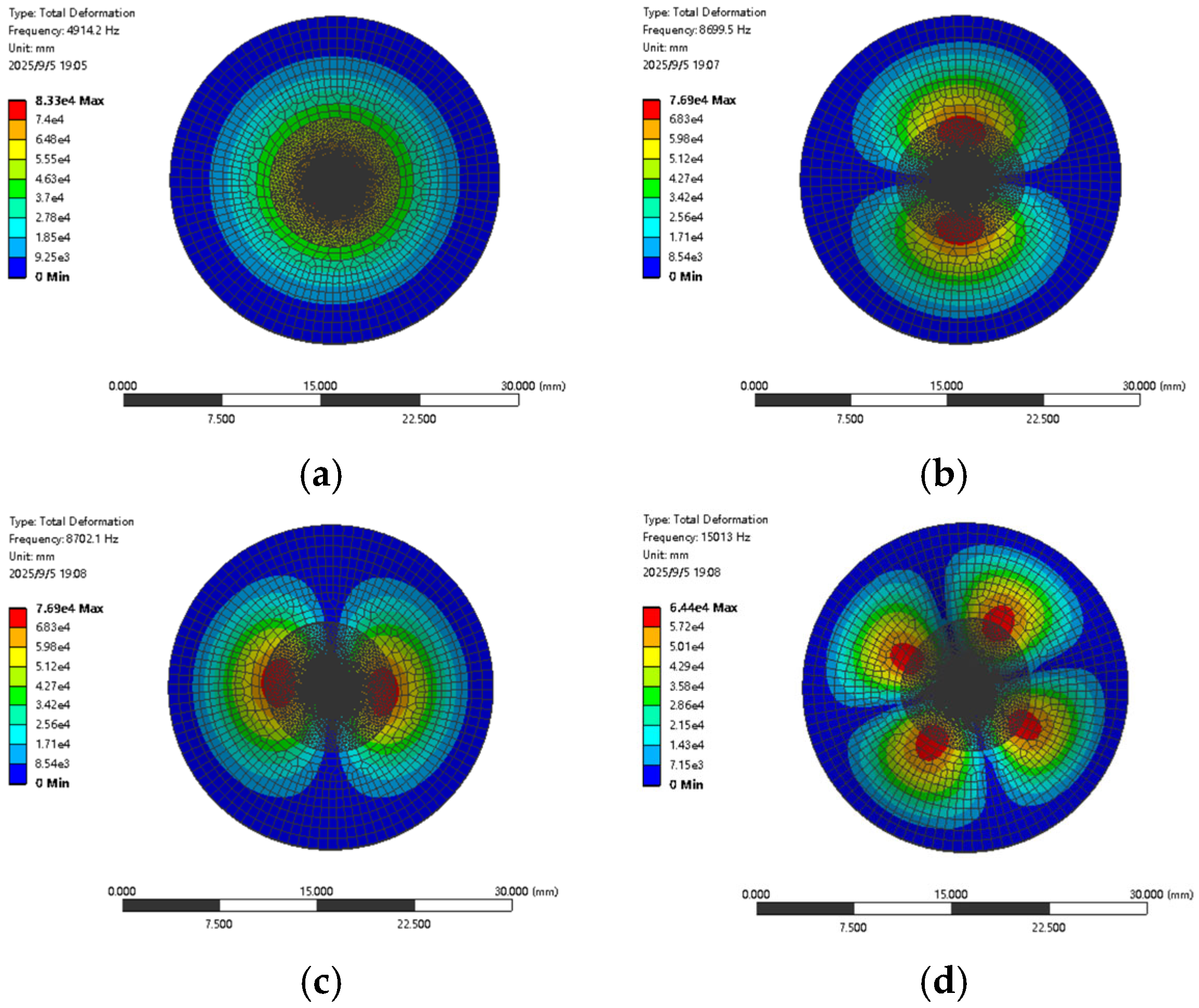
Using ANSYS for modal analysis, the vibration-mode analysis results of the piezoelectric oscillator in a vacuum state are shown in
Table 2, and the first four modes are taken as shown in
Figure 6.
Figure 6a shows the first-order modal shape of the piezoelectric oscillator, with a vibration frequency of 4914.2 Hz. It can be seen from the figure that the deformation region is mainly concentrated in the center position, presenting a displacement field that gradually decays from the center to the edge. This displacement-field distribution causes vibration energy to continuously accumulate towards the central region, thereby significantly increasing the amplitude of the central region. At the same time, particles on the same radius of the piezoelectric oscillator not only maintain the same vibration direction, but also have identical displacement sizes. During a vibration cycle, when the piezoelectric oscillator vibrates upwards, a positive pressure is formed, and the device begins to absorb oil; when the piezoelectric oscillator vibrates downwards, negative pressure is formed and the device begins to spray oil.
Figure 6b and
Figure 6c, respectively, present the second-order and third-order modal shapes of the piezoelectric oscillator, with vibration frequencies of 8699.5 Hz and 8702.1 Hz, respectively. It can be seen from the figures that the oscillator has two deformation regions with axisymmetric distributions. At the same time, the vibration directions of these two deformation regions are not the same, and the deformation does not cover the central region, which results in fewer pressure waves generated in the axial position, which is not conducive to the formation of ejected droplets.
Figure 6d shows the fourth-order modal shape of the piezoelectric oscillator. When the vibration frequency of the oscillator is 15,013 Hz, the figure shows the existence of four deformation zones. Overall, the area of these deformation regions is relatively small and the relative volume-change rate is also small, resulting in the smallest pressure-wave amplitude compared to the first three modes. At the same time, the vibration directions of the four deformation zones are inconsistent, and the deformation also does not cover the central area, resulting in less energy accumulation of the axial pressure wave and difficulty in effectively driving the droplet.
Based on the above analysis, the first-order modal shape of a piezoelectric oscillator operating under vacuum conditions can better meet the injection conditions. Therefore, determining the first-order mode as its working mode not only facilitates quantitative control of droplet ejection, but also facilitates the processing and assembly of the entire device.
3.2. Analysis of Vibration Characteristics
In the operation system of the oil-supply device, the piezoelectric oscillator serves as the core driving component. When an external excitation pulse acts on the oscillator, the generated acoustic-pressure wave will directly drive the oil to form a jet flow, thus completing the lubrication operation. During this process, the vibration characteristics of the oscillator exhibit the following effects: on the one hand, the energy-transfer efficiency generated by the vibration determines the total volume of the ejected droplets, which is directly related to the amount of fuel supplied in a single operation; On the other hand, the intensity and rhythm of vibration can alter the spray velocity of droplets, thereby affecting the coverage and penetration depth of the lubrication area. Therefore, in order to achieve precise control of fuel-supply quantity and speed, it is necessary to conduct transient analysis of the vibration characteristics of piezoelectric oscillators. The analysis of the vibration characteristics of piezoelectric oscillators mainly focuses on the resonance frequency of piezoelectric oscillators, the amplitude, velocity, and displacement variation of oscillator particles. The vibration characteristics of piezoelectric oscillators are influenced by various factors, such as the waveform, frequency, voltage amplitude of the excitation pulse, the thickness of the piezoelectric ceramic, and the thickness of the metal sheet.
In order to systematically reveal the influence mechanism of each parameter, this study uses the control-variable method to carry out comparative analysis [
26]. Ensuring the other conditions remain unchanged, the independent action law of the three key parameters of the excitation-pulse waveform, frequency, and voltage amplitude on the amplitude and vibration period of the vibrator particle is explored. Based on ANSYS, the transient dynamics simulation of the piezoelectric vibrator is carried out to clarify the influence of different parameters on its dynamic response behavior, which provides a theoretical basis for the subsequent optimization of the control strategy of the oil-supply device, and finally realizes the accurate control of the oil-supply quantity and the oil-supply speed.
3.2.1. Waveform
In order to study the influence of excitation-pulse waveform on the vibration characteristics of piezoelectric oscillators, and to select appropriate excitation-pulse waveform for piezoelectric oscillators. This article selects three waveforms as driving pulses: sine wave, triangular wave (rising edge time–falling edge time = 1:1), and square wave (duty cycle of 50%). The working frequency of the piezoelectric oscillator is 4914.2 Hz. In order to better meet the engineering application, the voltage amplitude is 220 V. Continuous pulse excitation is applied to compare the changes in the displacement and period of the particle vibration located at the center of the piezoelectric oscillator.
From
Figure 7 and
Table 3, it can be seen that under the same voltage and vibration frequency, different waveforms have a significant impact on the displacement change in piezoelectric oscillator particles. The displacement change generated by square-wave pulse excitation is the largest, with a displacement response amplitude of about 0.23157 mm at t = 1770 µs; the displacement change generated by sine-wave pulse excitation is second, with a displacement response amplitude of about 0.21615 mm at t = 1980 µs; the displacement change generated by triangular-wave excitation is the smallest, with a displacement response amplitude of about 0.20422 mm at t = 2186 µs.
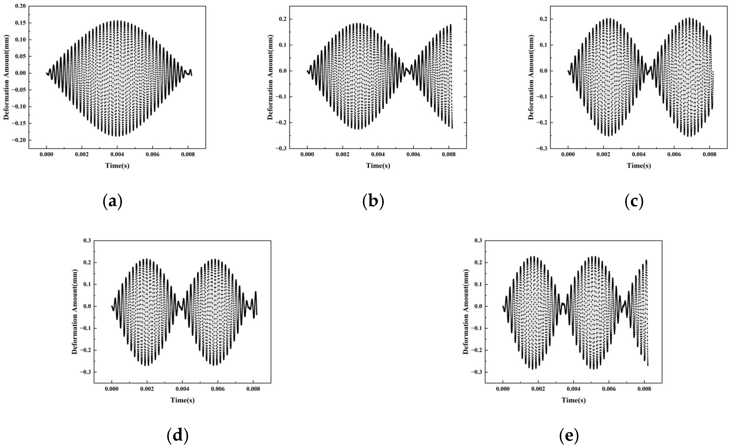
This difference arises from the energy-transfer characteristics of different waveforms: square waves form strong instantaneous impact forces with extremely short rise times, coupled with longer peak maintenance times, which can continuously output high-intensity energy. At the same time, their rich spectral components can effectively stimulate system resonance, and the synergistic effect of the three significantly improves the efficiency of converting electrical energy into mechanical kinetic energy, thereby driving the particle to produce maximum displacement; sine waves are limited by the energy distribution of a single-frequency component and cannot excite multiple resonant modes, with displacement response amplitudes naturally taking second place; however, triangular waves have the lowest energy-conversion efficiency due to their gentle waveform changes and lack of high-frequency energy, resulting in the smallest displacement response amplitude. From the perspective of fuel-supply demand, the displacement response amplitude is directly related to the sound-pressure intensity and fuel-supply quantity. Given the demand for the “small amount multiple times” fuel-supply mode in practical applications, the displacement characteristics of sine waves are more in line with this requirement.
Further analysis reveals that different driving-pulse waveforms also have a significant impact on the displacement response period of piezoelectric oscillator particles. The displacement response period under square-wave excitation is the shortest, only 3540 µs; under sine-wave excitation, the period is centered, at 3960 µs; under triangular-wave excitation, the period is extended to 4372 µs, showing a significant gradient difference.
This phenomenon is closely related to the spectral energy distribution of the excitation signal: the wideband characteristics of square waves enable them to excite more high-order short-period vibration modes, and significantly shorten the overall response period through modal coupling effects; the low-pass characteristic of triangular waves can only effectively drive long-period fundamental frequency vibrations, resulting in the longest response period; as a single-frequency excitation source, the response period of the sine wave is dominated by the fundamental frequency mode; thus, it falls between the two. From the perspective of fuel-supply stability, a long response period can easily lead to disrupted fuel-supply rhythm. However, the periodic characteristics of sine waves can ensure stable fuel-supply frequency and meet the requirements of long-term operation continuity. Therefore, sine waves are selected as the excitation waveform.
3.2.2. Frequency
In order to study the influence of excitation-pulse driving frequency on the vibration characteristics of piezoelectric oscillators, this paper uses a sine wave as the excitation waveform, maintains the driving voltage constant at V = 200 V, and modifies the value of pulse frequency f. Compare the changes in displacement and frequency of particle vibration located at the center of a piezoelectric oscillator by applying continuous pulse excitation.
From
Figure 8 and
Table 4, it can be seen that the matching relationship between the driving frequency and the resonant frequency of the piezoelectric oscillator has a significant regulatory effect on the displacement response amplitude. When the driving frequency is much lower than the resonant frequency of the oscillator, the displacement response amplitude shows a synchronous decreasing trend with the decrease in the driving frequency; when the driving frequency is exactly equal to the resonant frequency, the displacement response amplitude reaches a peak of 0.21615 mm, which is about 10 times that of the non-resonant state, exhibiting a strong resonance enhancement effect; when the driving frequency is much higher than the resonant frequency, the displacement response amplitude drops to 0.01727 mm, which is only about 1/12 of the resonant state.
This significant difference is due to the resonance characteristics of the vibration system: at the resonance frequency, the piezoelectric oscillator is in a mechanical resonance state, and the mechanical impedance of the system is minimized. The input electrical energy can be maximally converted into mechanical vibration energy, thereby driving the particles to produce the maximum displacement. The increase in particle displacement directly causes the vibration velocity to climb to its peak, thereby maximizing the amplitude of the sound pressure pulse wave radiated by the oscillator. The amplitude of the sound-pressure pulse wave has a decisive impact on the initial formation of lubricating oil droplets, the degree of atomization and fragmentation, and the transportation distance. The larger the amplitude, the easier it is for oil droplets to overcome surface tension and form small droplets, and can achieve precise transportation over longer distances under pressure.
Further analysis of the relationship between displacement-response frequency and driving frequency reveals that the displacement-response frequency is consistently significantly lower than the driving frequency, and there is no linear correlation between the two. Specifically, when the driving frequency is much lower than the resonant frequency of the oscillator, the displacement-response frequency shows a significant attenuation trend; When the driving frequency matches the resonant frequency, the displacement-response frequency reaches its maximum value of 252 Hz; however, when the driving frequency is much higher than the resonant frequency, the displacement-response frequency drops sharply to 42 Hz, which is only 1/6 of the resonant state.
The core mechanism of this phenomenon lies in the constraint effect of system inertia: the motion of the oscillator particles has inertia delay, making it difficult for them to quickly follow the high-frequency driving signal, resulting in displacement-response always lagging behind the driving pulse. When the driving frequency deviates from the resonant frequency, the decrease in displacement-response frequency will directly cause an increase in the interval of sound pressure pulse waves, accompanied by a significant attenuation of amplitude. The sparser and weaker the pulse waves, the more difficult it is to maintain the continuous pressure field required for the formation of lubricating oil droplets, thereby affecting the stability and continuity of the oil film. In sharp contrast, in the resonant state, the conversion efficiency of the vibration energy of the piezoelectric oscillator into sound energy reaches its peak, and the sound pressure intensity radiated by the system is the strongest. This high-intensity and high-frequency pressure fluctuation can effectively promote the periodic formation and fracture of oil droplets, providing a key guarantee for stable oil supply.
3.2.3. Voltage Amplitude
In order to study the influence of excitation-pulse amplitude on the vibration characteristics of piezoelectric oscillators, this paper uses a sine wave as the excitation waveform, maintains the frequency constant f = 4914.2 Hz, and modifies the value of pulse amplitude Vm. By applying continuous pulse excitation, the variation laws of particle vibration displacement and vibration period located at the center of the piezoelectric oscillator are compared.
From
Figure 9 and
Table 5, it can be seen that under the condition that the excitation-pulse waveform is consistent with the vibration frequency, the displacement-response peak and pulse amplitude of the piezoelectric oscillator particle show a significant monotonic increasing relationship, that is, the larger the pulse amplitude, the larger the displacement-response peak. When the voltage amplitude is 70 V, the displacement-response amplitude of the piezoelectric oscillator particle is the smallest, only 0.15631 mm; when the voltage amplitude is increased to 220 V, the displacement-response amplitude increases to 0.21615 mm; and when the voltage amplitude reaches 270 V, the displacement-response amplitude reaches the maximum value, which is 0.22722 mm.
The root of this change pattern lies in the characteristics of the piezoelectric effect: when the voltage applied to the piezoelectric oscillator increases, the piezoelectric stress generated inside the piezoelectric material will also increase, thereby promoting greater displacement changes in the piezoelectric oscillator particles. The increase in the maximum displacement of a particle will directly lead to an increase in the amplitude of the pressure wave generated by the piezoelectric oscillator. The increase in pressure-wave amplitude is extremely beneficial for the formation of lubricating oil droplets, especially for high-viscosity aviation oil. A higher amplitude can effectively overcome its flow resistance, avoid high-temperature areas in the oil circuit due to blockage, and reduce the loss of mechanical vibration energy during transmission.
Moreover, the magnitude of the driving pulse also has a significant impact on the displacement-response period of the piezoelectric oscillator particles, manifested as the larger the driving-pulse amplitude, the shorter the displacement-response period. Specifically, when the voltage amplitude is 70 V, the displacement-response period of the piezoelectric oscillator particle is the longest, reaching 8036 µs; while when the voltage amplitude increases to 270 V, the displacement-response period is shortened to 3548 µs, becoming the shortest period.
There are two main reasons for this phenomenon: on the one hand, as the voltage increases, the vibration energy obtained by the piezoelectric oscillator significantly increases, causing the vibration period to be shortened from 8036 µs to 3548 µs, a decrease of 56%; on the other hand, larger amplitude vibrations can cause geometric nonlinear deformation forces in materials, which increase the effective stiffness of the system and further accelerate the shortening of the vibration period, thus forming a strong negative correlation between voltage and period.
4. Conclusions
Through simulation analysis of the vibration characteristics of piezoelectric oscillators, the following conclusions can be drawn:
(1) Excitation waveform—sine wave. When using a sine wave as the driving signal, the displacement-response amplitude of the piezoelectric oscillator is at a moderate level. This feature enables it to meet small but multiple fuel-supply demands, as a stable amplitude output ensures that the amount of fuel supplied is roughly consistent each time, avoiding situations where a single fuel supply is too much or too little. Meanwhile, sine waves have the characteristic of periodic stability, and this regular vibration pattern provides convenient conditions for adjusting the driving strategy. By fine-tuning the parameters of the sine wave, the vibration state of the piezoelectric oscillator can be accurately controlled, thereby achieving stable operation of the entire fuel-supply process.
(2) Excitation frequency—4914.2 Hz. When the piezoelectric oscillator is in resonance, its displacement response will reach its peak. At this point, the vibration intensity of the oscillator is significantly increased, which can generate stronger acoustic-pressure waves. This powerful acoustic-pressure wave, when interacting with the oil, can more effectively promote the movement of the oil, significantly enhance the spraying effect of the oil, and promote better atomization of the oil. In addition, the vibration-period characteristics under resonance state can effectively regulate the formation and fracture process of oil droplets. It can promote the formation of oil droplets according to a fixed periodic pattern, and then break at the appropriate time, providing a key guarantee for stable oil supply and ensuring that the oil can be continuously and evenly sprayed out.
(3) Excitation voltage—220 V. Choosing this voltage value not only meets the general requirements of engineering application scenarios, but also better satisfies the adaptability of the driving circuit board. Although the larger the amplitude of the pulse voltage, the better the spraying effect of the oil, which can more effectively spray the oil, as the amplitude increases, the amount of liquid droplets generated by a single pulse will also increase accordingly. For micro-spray devices, their main function is to provide long-term micro replenishment of lubricating oil for the equipment. If the single-pulse injection volume is too large, it may not only lead to waste of lubricating oil, but also have adverse effects on the equipment due to excessive oil supply. Therefore, considering the long-term micro fuel-supply demand of the micro-spray device, the amplitude of the pulse voltage should not be set too large to ensure the accuracy and continuity of fuel supply.


