Abstract
On-machine measurement is a highly effective approach for enhancing machining accuracy and efficiency. A critical factor influencing the accuracy of on-machine measurements is the straightness error of the linear guideway. However, this error is significantly affected by environmental factors such as temperature, vibration, and gravity deformation. To improve the measurement accuracy of machine tools, this study investigates the impacts of these factors on straightness errors and proposes an innovative separation and compensation model for linear guideway straightness. A thermo-mechanical coupling simulation is employed to establish a model that quantifies the influence of thermal errors on straightness. The results demonstrate that thermal gradients cause the straightness error to bend to varying degrees, depending on the temperature distribution. Furthermore, a vibration error model is developed, revealing that the vibration period is approximately twice the ball diameter. Notably, vibration errors can be effectively mitigated using a band-stop filter to eliminate the corresponding frequency components. The study also addresses the effect of gravity deformation, comparing the deformation under different support conditions, highlighting the significance of precise support positioning. Through experimental validation of the straightness error separation and compensation model, it is shown that the straightness error of a conventional linear guideway can be reduced by 95%, and the compensated straightness error is less than 0.2 μm. This novel approach not only improves the accuracy of on-machine measurement but also provides valuable insights for optimizing machine tool performance under dynamic operating conditions.
1. Introduction
On-machine measurement is widely used in various machining fields such as milling [1], grinding [2], and cutting [3]. However, the application of on-machine measurement is significantly constrained by the inherent accuracy limitations of precision machine tools. On-machine measurement accuracy can be effectively improved through straightness error compensation. Ordinary precision machine tools use linear guideways as motion axes. The straightness error of the linear guideway is determined by the manufacturing accuracy of the mounting base and the guideway [4,5]. Straightness can be improved by adjusting the preload screw and manually grinding the mounting surface, but these methods are costly and limited in improving accuracy. Compared to alternative approaches, error compensation techniques demonstrate significant effectiveness in enhancing linear guideway straightness accuracy.
Many scholars have proposed various straightness error measurement and compensation methods, including laser interferometer, laser tracker, and self-collimator methods [5,6,7,8]. Huang et al. proposed a real-time separation of various geometric errors based on a multi-degree-of-freedom laser interferometer, including the effect of straightness error, and established a model for the effect of Abbe error due to the installation position of the mirror, which can effectively improve the accuracy of machine tools [9]. Fenget et al. developed a B-spline approximation methodology for straightness error characterization, integrating laser interferometry metrology with CNC systems to achieve an over 90% error reduction. Post-compensation residual errors were maintained below 10 μm using this integrated approach [10]. A laser interferometer can quickly measure the straightness error of the machine tool, but the straightness separation accuracy of the laser interferometer is limited, and the straightness measurement accuracy of the commercial laser a interferometer is about 0.5 μm [11,12]. The straightness error separation based on laser interferometer is not able to meet the requirements of sub-micron accuracy of the straightness error separation, and it is necessary to further explore the higher accuracy of straightness error separation method. Li et al. proposed using a laser tracker to separate the spatial positioning error of machine tools, but its separation accuracy can only be up to the micron level [13].
Currently, the manufacturing accuracy of high-precision straightedges has been able to be better than 0.1 μm/500 mm, and the separation of straightness error can be realized quickly with high-precision straightedges, and it is easy to separate the Abbe error [14,15]. However, when the straightness error separation accuracy reaches sub-micron levels, the straightness error is also affected by temperature, vibration, and other factors [16,17,18]. Wang et al. investigated the temperature change in a linear guideway under different load conditions, and the surface temperature of the linear guideway increases by about 2 °C at a speed of 20 m/min [19]. Thermal errors are difficult to accurately model and measure in real time [18,20]. To overcome the effect of temperature on the moving axes, Henselmans, R., built an additional measurement frame using low thermal expansion materials and combined it with a high-precision straightedge to compensate for the temperature error in real time [21]. In terms of linear guideway vibration, the cyclic periodic motion of the balls is the direct source of linear guideway vibration [22], but the vibration error is random, and there are few relevant reports that consider the effect of vibration error on straightness error separation. In summary, straightness error is the key factor affecting on-machine measurement, and there are few studies focusing on the uncertainty of straightness error separation and compensation. However, on-machine measurement puts forward higher requirements on straightness error of machine tools, and it is necessary to comprehensively consider the effects of temperature, vibration, gravitational deformation, and other factors on straightness error separation and compensation.
In order to improve the compensation accuracy of the straightness error of machine tools, the paper investigates the influencing factors of the separation accuracy of linear guideway straightness error. A straightness error model was established based on the high-precision straightedge to study the effect of temperature difference on straightness error based on thermal coupling simulation, establish a vibration model of the linear guideway to analyze the vibration amplitude and frequency, and further analyze the effect of gravity deformation of the straightedge on straightness error separation. The effects of temperature, vibration, and gravity deformation of the straightedge are verified through experiments, and the experimental results tend to be consistent with the theoretical analyses. Finally, the straightness error is separated and compensated, which can effectively improve the straightness error of the machine tool.
2. Straightness Error Separation Model
The straightness error is the key error that affects the accuracy of the machine tool. According to international standards ISO 230-1:2012(E) [23], the straightness error defined in the paper is the straightness error of the moving parts. The minimum straightness error is obtained by using the minimum zone reference straight line [24]. Common straightness error measurement methods include the laser interferometer method and the straightedge method [23,25]. The basic principle of the straightedge method is to obtain the straightness error of the guideway by measuring the specified workpiece with a displacement sensor [26,27,28]. The straightness error measured by the straightedge method is a superposition of the straightedge surface error and straightness error. Therefore, in order to separate the effect of straightedge surface error on straightness measurement, it is often necessary to separate the straightness error with multiple sensors [29,30]. However, with the development of ultra-precision manufacturing technology, the current manufacturing accuracy of precision straightedges can be better than 0.1 μm/500 mm, which can already be applied to measure the straightness of ordinary precision machine tools [31]. In the paper, the straightness error measurement accuracy of an ordinary linear guideway is required to be better than 0.5 μm. Therefore the surface error of the precision straightedge is negligible. The straightedge method can be directly simplified through a single sensor for measurement.
As shown in Figure 1, the basic structure of the straightedge method for measuring straightness error consists of a marble base, a linear guideway, an installation platform, a precision straightedge, and a displacement sensor. The data obtained from the displacement sensor is the superposition of the straightedge surface error z3(x) and the guideway straightness error Ez(x), in which the guideway straightness error can be divided into low-frequency deformation error z1(x) and high-frequency vibration error z2(x), as shown in Equation (1). Low-frequency deformation error is affected by thermal gradients, vibration error is mainly generated by the periodic motion of the balls, and straightedge surface error is related to the gravitational deformation.
where z1(x) is the low-frequency straightness error; z2(x) is the high-frequency vibration error; z3(x) is the straightedge surface error.
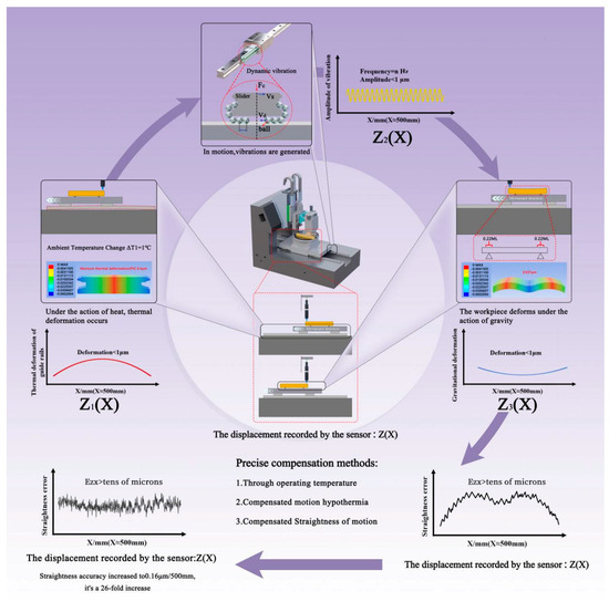
Figure 1.
Linear guideway straightness error separation model.
2.1. Low Frequency Straightness Error z1(x)
Linear guideway straightness error can be divided into low-frequency straightness error z1(x) and high-frequency straightness error z2(x). Low-frequency straightness error is mainly caused by clamping deformation. As shown in Figure 2a, the low-frequency straightness error is determined by the bottom surface of the guideway and the upper surface of the marble base together under preload F. However, the temperature difference between the upper and lower surfaces of the marble base is generated due to ambient temperature, friction, and other factors [32]. Since the ambient temperature of the machine tool fluctuates greatly, it is necessary to analyze the effect of temperature difference on the straightness error. As shown in Figure 2c, when the upper surface temperature is higher than the lower surface temperature, the marble surface is raised. As shown in Figure 2d, when the upper surface temperature is lower than the lower surface temperature, the marble surface will be concave [33]. Assuming that the temperature difference between the upper and lower surfaces of the marble base is ΔT, the maximum bending error of the marble surface is linearly related to the temperature difference, which can be expressed as Equation (2):
where f(x) is the thermal deformation function, k is the coefficient of proportionality between the temperature difference and the maximum bending deformation, α is the coefficient of thermal expansion, L is the length of the base, h is the thickness of the base, ΔT is the temperature difference between the upper and lower surfaces, and ΔT = T1 − T0.
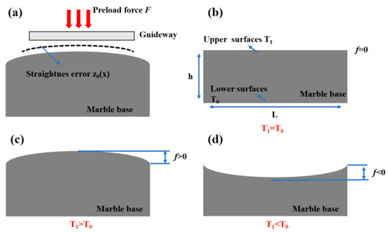
Figure 2.
Temperature difference effect on straightness error. (a) Causes of linear guideway low-frequency straightness error. (b) Effect of temperature difference on straightness error separation (T1 = T0). (c) Effect of temperature difference on straightness error separation (T1 > T0). (d) Effect of temperature difference on straightness error separation (T1 < T0).
The effect of temperature difference on straightness error is quantified through thermo-mechanical coupling simulation. Since the thickness of the linear guideway is negligible relative to the thickness of the marble base, the thermal deformation error of the marble base is mainly analyzed. It is assumed that the reference temperature of the bottom face is T0 and the reference temperature of the top face is T1. According to Fourier theory, the heat conduction equation under steady-state thermal conditions is d2T/dx2 = 0. According to this assumption, if the temperature difference between one face of the marble base and the other face is ∆T, the temperature distribution is linear.
Thermo-mechanical coupling analysis of the marble base was carried out with ANSYS Workbench 19.0 software, setting the initial temperature of the bottom surface at 22 °C, and the upper surface temperatures at 22.5 °C, 23 °C, 23.5 °C, i.e., the temperature difference was 0.5 °C, 1 °C, 1.5 °C, and 2 °C, respectively. Compare the thermal bending deformation of the marble base under different temperature differences. The simulated material is marble with a coefficient of thermal expansion of 2.70–9.00 µm/m-°C, thermal conductivity of 1.20–4.20 W/m-K, Young’s modulus of 60.0 GPa, and Poisson’s ratio of 0.3. The marble has a length of 500 mm and a height of 220 mm, and the constraints are bottom displacement constraints with zero displacement in the vertical direction. Figure 3 shows the bending curve of the marble surface under different temperature differences. From the simulation results, it can be seen that the bending degree of the marble surface is linearly related to the temperature difference. The theoretical scale factor k is 0.42 μm/°C.
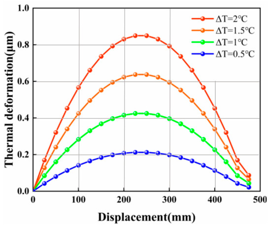
Figure 3.
Thermal bending deformation with different temperature differences.
2.2. Vibration Error z2(x)
The linear guideway will produce a fixed cycle of vibration; the vibration is mainly due to the cyclic movement of the ball [31], as shown in Figure 4. Assuming that the raceway is completely filled by the ball, there is no gap between adjacent balls, and the balls do pure rolling in the raceway. The slider moves at a constant speed, vc, relative to the fixed rail, then the relative speed, vs, of the center of the balls relative to the slider is vc/2. The balls move in and out of the raceway, generating a cyclic vibration. The vibration time period, T, can be calculated from moving speed, vc, as shown in Equation (3). The time period, T, is converted into a vibration displacement period, Tx, as shown in Equation (4):
where T is the guideway vibration time period, Tx is the guideway vibration displacement period, vs is the ball movement speed, vc is the slider movement speed, and D is the ball diameter.
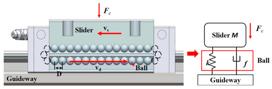
Figure 4.
Linear guideway motion models.
Further considering the ball as a spring body, the vibration model of the linear guideway can be simplified to the spring damping system as shown in Figure 4, letting the impact force generated during ball cycling be Fc.
The differential equation of motion of the guide according to Dalembert’s principle can be described as:
where f is the damping factor, k is the equivalent stiffness factor of the ball, and x is the displacement value of the ball.
We can obtain the following from the Laplace variation:
Letting s = jw, the frequency response function (FRF) is:
The vibration amplitude can be expressed as:
where the frequency is , the natural frequency is , and the damping ratio is
Substituting the natural frequency and damping ratio into Equation (8):
According to the vibration amplitude and vibration period, the vibration error in the linear guideway straightness error can be expressed as Equation (10):
2.3. Straightedge Surface Error
Since the straightedge bottom surface and the mounting surface are not ideal planes, gravitational deformation occurs when the straightedge is placed on the mounting platform. According to Bessel’s principle, the gravity deformation of the straightedge itself is minimized when the support point is located at the Bessel point [22]. A 500 mm × 50 mm × 50 mm precision straightedge made of microcrystalline glass is shown in Figure 5. The gravitational deformation is compared when supported at the two ends and when supported at Bessel’s point, respectively. The gravitational deformation is 0.4 μm for the two-end support and 0.037 μm for the Bessel point support.
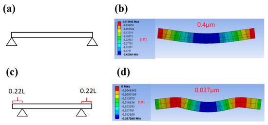
Figure 5.
Linear guideway gravitational deformation. (a) Two-sided support. (b) Gravity deformation of two-sided support. (c) Bessel point support. (d) Gravity deformation of Bessel point support.
Overall, taking into account the effects of temperature, vibration, and gravitational deformation, the straightness error is as shown in Equation (11).
where z0(x) is the initial low-frequency straightness error, zT(x) is the straightness error caused by temperature difference, zV(x) is the high-frequency straightness error caused by vibration, and zG(x) is the straightness error caused by straightedge clamping deformation. For the temperature error, zT(x), the straightness error changes by 0.4 μm for each 1 °C change in temperature difference. It is necessary to monitor the temperature of the upper and lower surfaces of the machine tool in real time, and when the temperature change is greater than the expected value, it is necessary to re-separate the straightness error with the straightedge. For the vibration error, zV(x), there is an inherent period of vibration of the linear guideway; in different applications, the impact of vibration error can be suppressed by means of a band-stop filter. For example, this paper is mainly applied to improve the on-machine measurement accuracy in the grinding process, and the grinding process is mainly interested in the frequency of low-frequency error, so it can be filtered by band-stop filtering to filter out the impact of medium- and high-frequency vibration error. For the straightedge clamping deformation error, zG(x), the clamping deformation can be controlled to be less than 50 nm by optimizing the clamping method, and then the straightedge clamping error is negligible.
3. Experimental Verification and Discussion
3.1. Experimental Setup
Figure 6 is the experimental setup; this paper used the HIWIN rolling linear guide and a ball diameter of 6.25 mm. The displacement sensor was an STIL CL2 MG140 color confocal sensor. The static noise was 7 nm, the maximum travel was 400 μm, and the maximum linearity error was 0.027 μm. The sensor sampling frequency was set to 500 Hz. The precision straightedge surface shape accuracy was better than 0.1 μm, and the precision straightedge surface error was as shown in Figure 6. The temperature error of the upper and lower surfaces of the marble base was also monitored using a PT100 temperature sensor.
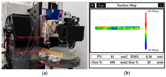
Figure 6.
(a) Straightness measurement setup. (b) Precision straightedge surface error.
3.2. Straightness Error at Different Temperature Differences
The indoor ambient temperature was adjusted by the temperature control system and the temperature was monitored in real time using the PT1000 temperature sensor (NB-PTC0-151). Four temperature sensors were arranged on each of the upper and lower surfaces, and the temperature measurements of the upper and lower surfaces were averaged. Temperature sensor resolution was 0.1 °C. The straightness error test results were observed under different temperature differences. The straightness error test results under temperature differences of 0.3 °C, 0.9 °C, 1.1 °C, and 1.4 °C were obtained by real-time temperature monitoring. Setting the straightness error when the initial temperature difference is 0.3 °C as the initial straightness error, the straightness errors caused by different temperature differences relative to the initial straightness error can be obtained, as shown in Figure 7 and Table 1. From Figure 7 and Table 1, it can be seen that the experimental scale factor of the change in straightness error caused by temperature difference is 0.48 μm/°C, which is close to the simulation results, but the experimental curve is not strictly in line with the parabolic shape, mainly due to the fact that the temperature step-by-step in the experimental process is not uniformly distributed as in the simulation results, and the PT100 temperature sensor is only tested for a certain area of the upper and lower surface temperature. Therefore, the actual temperature deformation error will be different from the theory, and it is difficult to compensate according to the temperature change, but it is necessary to remeasure the straightness error at different temperature moments. Due to the simulation conditions being difficult to be completely close to the actual situation, there is an error between the scale factor obtained by simulation and the actual value; the error is less than 20%. This is an acceptable range.
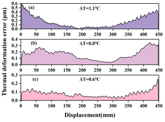
Figure 7.
Straightness error test results under different temperature differences. (a) ΔT = 1.1 °C. (b) ΔT = 0.8 °C. (c) ΔT = 0.6 °C.

Table 1.
Straightness error test results at different temperature differences.
3.3. Straightness Error at Different Speeds
According to Equation (4), the vibration displacement period is twice the ball diameter. When the diameter of the ball is 6.75 mm, the linear guideway has a vibration cycle of 13.5 mm in theory. The straightness errors under the linear guideway speeds of 400 mm/min, 800 mm/min, and 1600 mm/min were tested, respectively, as shown in Figure 8. Table 2 lists the straightness error test results at different speeds. From the results, it can be seen that the vibration displacement period is about 13~14 mm, which is close to the theoretical vibration period, and the displacement period of vibration at different operating speeds is suppressed. Due to actual measurement conditions, the deviation between the vibration results and the theoretical results is within an acceptable range. It is possible to set appropriate band-stop filtering parameters according to the displacement period to suppress the effect of vibration error. On the other hand, the larger the speed is, the larger the vibration error is, and the appropriate speed can be selected to reduce the effect of vibration error.
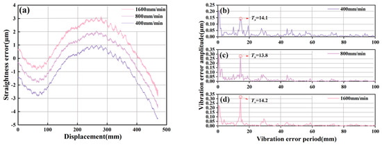
Figure 8.
Vibration error period test results at different speeds. (a) Straightness error at different speeds. (b) Spectrum diagram at a speed of 400 mm/min. (c) Spectrum diagram at a speed of 800 mm/min. (d) Spectrum diagram at a speed of 1600 mm/min.
Table 2.
Straightness error test results at different speeds.
To further illustrate the relationship between the vibration period and the diameter of the ball, linear guideways were tested. As shown in Table 3, the first guideway was the THK-SPR30, the second guideway was the HIWIN-HG35, and the third guideway was the GGB45AA manufactured by Nanjing Process Equipment Co, Nanjing, China. As can be seen from the table, the displacement vibration period of different types of guideways is directly proportional to the diameter of the ball and approximates to two times the diameter of the ball. The theoretical value of the vibration period is calculated using Equation (4).
Table 3.
Straightness error test results at different guideways.
3.4. Straightness Error at Different Straightedge Mounting Methods
To verify the gravitational deformation of the straightedge in different mountings, the straightness error test results of the precision straightedge supported at both ends and on the Bessel point support, respectively, was compared. The straightness error obtained from the best support point and the two-end support tests was different, and the difference between the two was 0.5 μm, and the shape was parabolic, which is consistent with the theoretical simulation results in Figure 9.
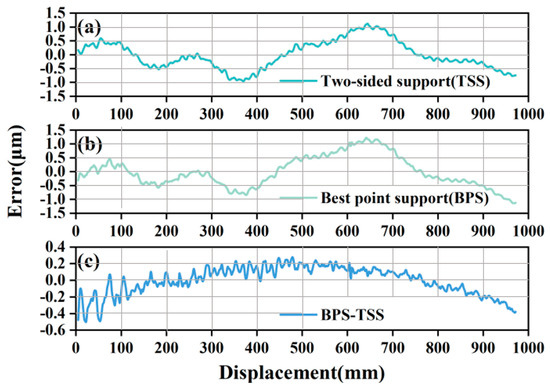
Figure 9.
Vibration error period test results at different speeds. (a) Gravitational deformation at two-end support. (b) Gravitational deformation at Bessel point support. (c) The difference between the two-end support and Bessel point support.
3.5. Straightness Error Separation and Compensation Experiment
After the above analyses and experiments, the straightness error separation accuracy of the linear guideway is affected by temperature, vibration, and straightedge gravity deformation. Among the factors affecting the repeatability of machine tool errors, vibration errors are approximately 0.2 μm, temperature gradient changes of 1 °C result in errors of 0.42 μm, and gravitational deformation errors are controlled to 0.037 μm.
Next, experiments were conducted to verify the linear guideway straightness error separation and compensation of the accuracy limit after controlling the above factors. Each set of data was measured three times, and the average value was taken. The temperature difference could be controlled by real-time temperature monitoring. The vibration error could be controlled by band-stop filtering, and the gravity deformation of the straightedge could be controlled by optimizing the clamping method. As shown in Figure 10, the straightness error was compensated; the straightness error before compensation was about 4.2 μm, and the straightness error after compensation was 0.22 μm. It should be noted that filtering does not really eliminate vibration errors. However, when the machine is used for on-machine measurement, the 12 mm to 16 mm cycle error is sometimes not taken into consideration. Then, the vibration error in this frequency band can be eliminated by using a band-stop filter. The study revealed that the peak-to-valley (PV) value of surface error in the 12–16 mm spatial wavelength range after grinding is 0.1 μm, which is significantly smaller than the total surface error (PV 11.4 μm), as shown in Figure 11. The result shows that the error in the 12~16 mm frequency band can be neglected during on-machine measurements of grinding workpieces. To avoid image distortion caused by filtering, this paper eliminated the vibration error by using the FFT filtering method. The band-stop filter band was set to 12~16 mm, and the straightness error could be reduced to 0.16 μm after band-stop filtering.
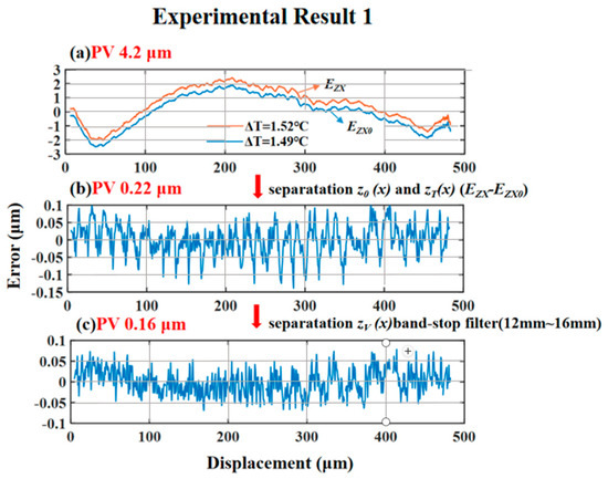
Figure 10.
Linear guideway straightness error separation and compensation. (a) Initial straightness error. (b) Straightness error after compensation. (c) Straightness error after band-stop filtering.
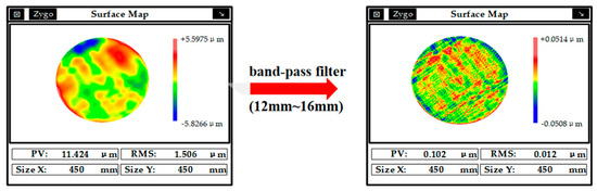
Figure 11.
Frequency analysis of surface error after grinding.
The effect of straightness error compensation under different temperature gradients was further tested. As shown in Figure 12, the straightness error is reduced from PV 4.0 μm to 0.17 μm after compensation in Experiment 2 and from PV 4.4 μm to PV 0.19 μm in Experiment 3. Overall, the straightness error of the machine tool can be reduced by 95% by controlling the factors of temperature and vibration, and the straightness error is better than 0.2 μm after compensation.
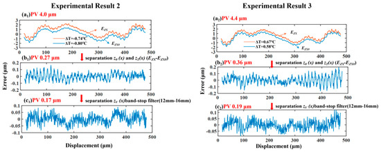
Figure 12.
Linear guideway straightness error separation and compensation at different temperature gradients.
3.6. Discussion
In past research, there are few papers that studied the influencing factors of straightness error compensation accuracy. This paper establishes a model of straightness error compensation accuracy, including the effects of thermal error, vibration error, and gravity deformation. For thermal error, the change in straightness error caused by temperature gradient is 0.48 μm/°C. For the vibration error, there are fixed displacement cycles of vibration in the straightness error. The displacement period is proportional to the diameter of the sphere. The effect of fixed-period vibration error can be effectively reduced by band-stop filtering. For the gravity deformation, when the straightness error measurement accuracy reaches sub-micron levels, the gravity deformation of the straightedge is not negligible. In the case of two-end support, the gravity deformation of the straightedge is 0.4 μm, and by optimizing the support method, the gravity deformation of the straightedge is less than 50 nm. Finally, the experiment shows that the straightness error can be significantly reduced by controlling the above three factors. The straightness error compensation effect is better than 95%, and the error after compensation is less than 0.2 μm. The model proposed in this paper has greater engineering significance, especially to improve the machine tool on-machine measurement accuracy. But there are still some aspects that can be further explored:
Thermal errors are the main source of machine tool errors. Thermal errors can be divided into first-order thermal expansion errors, second-order thermal gradient errors, and higher-order thermal errors. First-order thermal errors affect the positioning accuracy of the machine tool. Second-order thermal gradient errors affect the straightness error of the machine tool and are the main research subject of this paper. Higher-order thermal errors, such as uneven temperature distribution, inconsistent material thermal properties, and other higher-order thermal errors, also affect straightness error. However, when the temperature reaches the steady-state condition, the influence of this part of the error is small. In the future, when higher accuracy of straightness error is required, the effect of higher-order thermal error on straightness error can be studied.
Vibration errors are introduced by the guideway structure. For different application scenarios, reasonably selecting the diameter of the ball bearings in the linear guide can reduce vibration errors. Bolt preload and motion load will also affect the amplitude of the vibration error but will not affect the vibration displacement period.
The straightness error measured in this paper is over a 500 mm travel distance; when measuring straightness errors over large travel distances, a longer precision straightedge is required. Longer precision rulers produce greater gravitational deflections. For example, a precision straightedge with a length of 1 m and a thickness of 60 mm will produce a gravitational deformation of 0.3 μm even at the Bessel support point. In this case, it is necessary to use multiple support points to reduce the effect of gravity deformation or use the splicing method to measure the straightness error.
4. Conclusions
This paper establishes a linear guideway straightness error separation model based on a precision straightedge. The influence of temperature difference, vibration, and gravity deformation on the accuracy of straightness error separation is considered in the model. The effectiveness of the model is verified through experimentation and simulation. Based on the model, the separation and compensation method can effectively reduce the straightness error. The main research conclusions are as follows:
1. The establishment of the temperature difference on the straightness error model. for the linear guideway structure of this paper, the temperature difference in each change in 1 °C guide straightness error changes 0.42 μm under theoretical conditions. When the temperature difference is too large, changes in the need for a high-precision straightedge and re-separation of straightness error occur.
2. Theoretical and experimental proof that there is a periodic vibration in the linear guideway straightness error, and the vibration displacement period for the ball diameter is twice. When the linear guide speed increases, the vibration period remains constant and the vibration amplitude increases. The influence of periodic vibration can be reduced by band-stop filtering and selecting an appropriate running speed.
3. Through simulation analysis and experiments, the surface of the long-stroke high-precision straightedge will be affected by gravity deformation. Based on Bessel’s principle, the relationship between the straightedge’s gravity deformation and the support point is established, and the straightedge’s gravity deformation can be minimized by choosing the appropriate support point.
4. Finally, after controlling the effects of temperature, vibration, and gravity deformation. The straightness error of the linear guideway is separated and compensated with a high precision straightedge, and the straightness error can be reduced by 95%, which effectively improves the straightness error of the linear guideway.
In summary, this paper describes in detail the influencing factors in the process of separating the straightness error of a precision straightedge. By controlling the relevant variables, the straightness error of the linear guideway can be separated quickly, and the method is universal and can be used to guide the straightness error separation and compensation of any linear guideway machine tool.
Author Contributions
Conceptualization, Z.L.; Methodology, Z.L.; Investigation, Y.D. and Y.Z.; Resources, Y.D.; Writing – original draft, Z.L.; Writing – review & editing, Z.L.; Visualization, T.L.; Supervision, T.L. and S.L. All authors have read and agreed to the published version of the manuscript.
Funding
This research received no external funding.
Data Availability Statement
The original contributions presented in this study are included in the article. Further inquiries can be directed to the corresponding author.
Conflicts of Interest
The authors declare no conflict of interest.
References
- Ibaraki, S.; Kimura, Y.; Nagai, Y.; Nishikawa, S. Formulation of influence of machine geometric errors on five-axis on-machine scanning measurement by using a laser displacement sensor. J. Manuf. Sci. Eng. 2015, 137, 021013. [Google Scholar] [CrossRef]
- Wang, S.; Zhao, Q. Development of an on-machine measurement system with chromatic confocal probe for measuring the profile error of off-axis biconical free-form optics in ultra-precision grinding. Measurement 2022, 202, 111825. [Google Scholar] [CrossRef]
- Dai, G.; Zhang, Q.; Xu, X.; Zhao, B. A calibration method of line-structured light system for measuring outer circle dimension during machining. Results Eng. 2024, 23, 102525. [Google Scholar] [CrossRef]
- Tong, V.-C.; Kwon, S.-W.; Hong, S.-W. Modeling of moving table with linear roller guides subjected to geometric errors in guide rails. Int. J. Precis. Eng. Manuf. 2020, 21, 1903–1919. [Google Scholar] [CrossRef]
- Majda, P. Modeling of geometric errors of linear guideway and their influence on joint kinematic error in machine tools. Precis. Eng. 2012, 36, 369–378. [Google Scholar] [CrossRef]
- Zha, J.; Xue, F.; Chen, Y. Straightness error modeling and compensation for gantry type open hydrostatic guideway in grinding machine. Int. J. Mach. Tools Manuf. 2017, 112, 1–6. [Google Scholar] [CrossRef]
- Zha, J.; Wang, T.; Li, L.; Chen, Y. Volumetric error compensation of machine tool using laser tracer and machining verification. Int. J. Adv. Manuf. Technol. 2020, 108, 2467–2481. [Google Scholar] [CrossRef]
- Li, J.; Xie, F.; Liu, X.J.; Li, W.; Zhu, S. Geometric error identification and compensation of linear axes based on a novel 13-line method. Int. J. Adv. Manuf. Technol. 2016, 87, 2269–2283. [Google Scholar] [CrossRef]
- Huang, Y.B.; Fan, K.C.; Lou, Z.F.; Sun, W. A novel modeling of volumetric errors of three-axis machine tools based on Abbe and Bryan principles. Int. J. Mach. Tools Manuf. 2020, 151, 103527. [Google Scholar] [CrossRef]
- Feng, W.L.; Yao, X.D.; Azamat, A.; Yang, J.G. Straightness error compensation for large CNC gantry type milling centers based on B-spline curves modeling. Int. J. Mach. Tools Manuf. 2015, 88, 165–174. [Google Scholar] [CrossRef]
- Chen, G.; Zhang, L.; Wang, X.; Wang, C.; Xiang, H.; Tong, G.; Zhao, D. Modeling method of CNC tooling volumetric error under consideration of Abbé error. Int. J. Adv. Manuf. Technol. 2022, 119, 7875–7887. [Google Scholar] [CrossRef]
- Liu, H.; Xiang, H.; Chen, J.; Yang, R. Measurement and compensation of machine tool geometry error based on Abbe principle. Int. J. Adv. Manuf. Technol. 2018, 98, 2769–2774. [Google Scholar] [CrossRef]
- Li, Q.; Wang, W.; Zhang, J.; Shen, R.; Li, H.; Jiang, Z. Measurement method for volumetric error of five-axis machine tool considering measurement point distribution and adaptive identification process. Int. J. Mach. Tools Manuf. 2019, 147, 103465. [Google Scholar] [CrossRef]
- Gao, W.; Tano, M.; Araki, T.; Kiyono, S.; Park, C.H. Measurement and compensation of error motions of a diamond turning machine. Precis. Eng. 2007, 31, 310–316. [Google Scholar] [CrossRef]
- Gao, W.; Ibaraki, S.; Donmez, M.A.; Kono, D.; Mayer, J.; Chen, Y.-L.; Szipka, K.; Archenti, A.; Linares, J.-M.; Suzuki, N. Machine tool calibration: Measurement, modeling, and compensation of machine tool errors. Int. J. Mach. Tools Manuf. 2023, 187, 104017. [Google Scholar] [CrossRef]
- Zhang, W.; Zhang, X.; Zhao, W. Influence of nonlinearity of servo system electrical characteristics on motion smoothness of precision CNC machine tools. Precis. Eng. 2023, 83, 82–101. [Google Scholar] [CrossRef]
- Mori, K.; Kono, D.; Matsubara, A. Effect of expansion coefficient difference between machine tool and workpiece to the thermal deformation induced by room temperature change. Procedia CIRP 2021, 101, 318–321. [Google Scholar] [CrossRef]
- Cheng, Q.; Zhang, H.; Zhang, T.; Li, Y.; Xu, J.; Liu, Z. Prediction method of precision deterioration of rolling guide under multi-random parameters based on frictional thermal expansion effect. Tribol. Int. 2023, 189, 108883. [Google Scholar] [CrossRef]
- Wang, X.Y.; Feng, H.T.; Zhou, C.G.; Ye, K.-Q. A thermal model for real-time temperature forecast of rolling linear guide considering loading working conditions. Int. J. Adv. Manuf. Technol. 2020, 109, 2249–2271. [Google Scholar] [CrossRef]
- Weng, L.; Gao, W.; Zhang, D.; Huang, T.; Duan, G.; Liu, T.; Zheng, Y.; Shi, K. Analytical modelling of transient thermal characteristics of precision machine tools and real-time active thermal control method. Int. J. Mach. Tools Manuf. 2023, 186, 104003. [Google Scholar] [CrossRef]
- Henselmans, R.; Cacace, L.A.; Kramer, G.F.Y.; Rosielle, P.C.J.N.; Steinbuch, M. The NANOMEFOS non-contact measurement machine for freeform optics. Precis. Eng. 2011, 35, 607–624. [Google Scholar] [CrossRef]
- Li, C.; Xu, M.; He, G.; Zhang, H.; Liu, Z.; He, D.; Zhang, Y. Time-dependent nonlinear dynamic model for linear Guideway with crowning. Tribol. Int. 2020, 151, 106413. [Google Scholar] [CrossRef]
- ISO 230-1:2022(E); Test Code for Machine Tools—Part 1: Geometric Accuracy of Machines Operating Under No-Load or Quasi-static Conditions. ISO: Geneva, Switzerland, 2022.
- Tao, H.; Chen, R.; Xuan, J.; Xia, Q.; Yang, Z.; Zhang, X.; He, S.; Shi, T. A new approach to identify geometric errors directly from the surface topography of workpiece in ultra-precision machining. Int. J. Adv. Manuf. Technol. 2020, 106, 5159–5173. [Google Scholar] [CrossRef]
- Zhang, H.; Dai, Y.; Lai, T. Highly accurate digital processing of large stroke guideway with an optical material-corning code 7972. Materials 2021, 14, 3809. [Google Scholar] [CrossRef]
- Breitzke, A.; Hintze, W. Workshop-suited geometric errors identification of three-axis machine tools using on-machine measurement for long term precision assurance. Precis. Eng. 2022, 75, 235–247. [Google Scholar] [CrossRef]
- Breitzke, A.; Hintze, W. Workshop-suited identification of thermo-elastic errors of three-axis machine tools using on-machine measurement. Precis. Eng. 2024, 85, 72–88. [Google Scholar] [CrossRef]
- Schulz, M.; Elster, C. Traceable multiple sensor system for measuring curved surface profiles with high accuracy and high lateral resolution. Opt. Eng. 2006, 45, 060503. [Google Scholar] [CrossRef]
- Hwang, J.; Park, C.H.; Gao, W.; Kim, S.W. A three-probe system for measuring the parallelism and straightness of a pair of rails for ultra-precision guideways. Int. J. Mach. Tools Manuf. 2007, 47, 1053–1058. [Google Scholar] [CrossRef]
- Yin, Z.; Chai, N.; Wang, S.; Huang, G.; Lin, J.; Zhao, R. Single probe shear scanning method for on-machine measurement of an optical profile. Appl. Opt. 2020, 59, 4718–4731. [Google Scholar] [CrossRef] [PubMed]
- Hennebelle, F.; Coorevits, T.; El Asmai, S.; Goutagneux, F.; Vincent, R. Impact of thermal gradients on the geometry correction of a bridge coordinate measuring machine. Meas. Sci. Technol. 2020, 32, 025002. [Google Scholar] [CrossRef]
- Cheng, J.M.; Liu, Z.; Jin, L.M.; Chen, J.H. Finite element calculation for surface shape optimization of a polished synchrotron radiation thin mirror based on Bessel-point supporting. Nucl. Instrum. Methods Phys. Res. Sect. A Accel. Spectrometers Detect. Assoc. Equip. 2022, 1042, 167458. [Google Scholar] [CrossRef]
- Li, Z.; Dai, Y.; Sun, Z.; Guan, C.L.; Lai, T.; Xu, H.; Zhou, X. A sub-micron precision machining and measurement method of long travel metal guideways. J. Manuf. Process. 2025, 133, 947–956. [Google Scholar]
Disclaimer/Publisher’s Note: The statements, opinions and data contained in all publications are solely those of the individual author(s) and contributor(s) and not of MDPI and/or the editor(s). MDPI and/or the editor(s) disclaim responsibility for any injury to people or property resulting from any ideas, methods, instructions or products referred to in the content. |
© 2025 by the authors. Licensee MDPI, Basel, Switzerland. This article is an open access article distributed under the terms and conditions of the Creative Commons Attribution (CC BY) license (https://creativecommons.org/licenses/by/4.0/).