Article

Comparison Between Active and Hybrid Magnetic Levitation Systems for High-Speed Transportation

1
Department of Mechanical and Aerospace Engineering, Politecnico di Torino, 10129 Turin, Italy
2
Center for Automotive Research and Sustainable Mobility, Politecnico di Torino, 10129 Turin, Italy
3
School of Engineering and Sciences, Tecnologico de Monterrey, Mexico City 14380, Mexico
4
SAS HYPERLOOP TT FRANCE, 31400 Toulouse, France
*
Author to whom correspondence should be addressed.
Appl. Sci. 2025, 15(17), 9793; https://doi.org/10.3390/app15179793
Submission received: 18 July 2025 / Revised: 2 September 2025 / Accepted: 4 September 2025 / Published: 6 September 2025
(This article belongs to the Section Transportation and Future Mobility)

Abstract

The development of alternative transportation methods has become paramount in the context of sustainable urban population connectivity. The promise of hyperloop as a high-speed, low-emission travel means motivates both academic and industrial interests. The present work centers on the design of hyperloop levitation systems. A component-level optimization is outlined for the appropriate selection of levitation module geometric parameters, followed by an integration into a capsule and bogie system. Two heteropolar levitation module types are numerically studied in realistic operating conditions: a hybrid electromagnet configuration with permanent magnets and a fully active one. To give means for comparison, both configurations are designed with the aid of a general multi-objective optimization approach. For the hybrid case, a position controller is synthesized with a zero-power policy and a specific frequency response function. The active configuration features comparable behavior. Two main power consumption streams are considered: gap control and magnetic drag. While the former depends on the position control effort, the latter depends on the losses of ferromagnetic elements. The two systems are compared in smooth and irregular track conditions over the studied speed range of 400–700 km/h. This study demonstrates that the hybrid heteropolar case achieves a minimum of 97.6% in specific power consumption reduction at the maximum speed of 700 km/h under smooth track conditions. Under irregular track conditions, a benefit in average specific consumption reduction is noted up to 662 km/h for the hybrid case. The maximum reduction in specific consumption is 57.2% at the minimum speed of 400 km/h.

1. Introduction

Contactless levitation in maglev vehicles ensures null power dissipated due to mechanical friction. Despite this advantage, maglev systems experience power dissipation due to the static or dynamic losses in their electromagnetic actuators. Nonetheless, maglev transportation exhibits potential for low-emission travel, particularly through the hyperloop concept. Characterized by speeds exceeding those reached by conventional high-speed rail, the hyperloop system also promises a reduction in aerodynamic drag with the use of a low-pressure tube. The feasibility of this transportation system depends in part on the appropriate design of its levitation system.

1.1. Previous Work

Levitation systems may be classified into two categories according to power consumption: active and passive. In the passive levitation branch, Halbach arrays of permanent magnets (PMs) are exploited to produce lift when a relative track speed is present, giving rise to an electrodynamic phenomenon. Previous work on electrodynamic suspension (EDS) involves the numerical modeling and treatment of instability [1], with models validated on a dedicated test bench, both passively [2] and actively [3]. In the realm of active electromagnetic suspensions (EMSs), electromagnets are used to produce the magnetic field, allowing for the possibility of null-speed levitation. The addition of PMs to electromagnets produces a hybrid variant, where bias force is provided by passive means and variations can be controlled actively. Zhang et al. addressed the selection of component-level parameters, concluding with a significant reduction in power consumption compared to active electromagnets [4]. The architecture is evaluated in the context of medium-to-low-speed maglev systems operating at atmospheric pressure. Hybrid levitation was also studied in [5], where rotary magnets and a developed control strategy were used to ensure zero-power conditions under eccentric loads. A recent study has investigated PM-assisted EMS regarding an associated zero-power control strategy [6]. Several studies regarding conventional EMS architectures have focused on controller design within the scope of vibration attenuation [7,8,9,10]. The work in [11] focused on controller development, aiming to manage track irregularities for a half-bogie system up to 430 km / h . An EMS system was analytically modeled and experimentally validated in [12], combining both lateral guidance and levitation functions. Levitation was achieved cryogenically with a homopolar magnet configuration. Moreover, nonlinear modeling using a magnetic circuit approach is performed in [13] and experimentally verified, offering advantages in design and optimization.
Previous work at the system level by Tudor and Paolone focused on an optimization methodology for hyperloop system sizing regarding battery and power electronics technology [14]. An assumption of null magnetic drag was adopted. The same authors considered the infrastructure, capsule kinematics, and system propulsion, optimizing energy consumption [15]. Energy consumption regarding propulsion and levitation was addressed in [16], with speed profile optimization for medium–low-speed systems. Other studies present experimental implementations of PM-assisted electromagnets in existing maglev vehicles [17,18]. Finite-element models are exploited in a multi-objective optimization, aiming to facilitate electromagnet integration in a maglev system [19].

1.2. Research Gap

Past work has seen extensive development and analysis of controllers targeting ride comfort and gap control for magnetic levitation. However their effects regarding power consumption related to track irregularities and iron losses at the system level remain largely unexplored. When track irregularities are included, they largely serve to evaluate controller performance. Furthermore, studied systems mainly fall under medium–low-speed applications in atmospheric conditions. Previous system-level work has studied power requests due to pressurization, propulsion, and capsule kinematics. A dedicated analysis of magnetic drag and control power for varying levitation topologies has not been conducted. Where levitation and propulsion power are included, the focus pertains to commercial operation rather than design. Where PM-assisted electromagnets have been tested, no focus is given to development from the component to the system level.

1.3. Objective and Novelty

The aim of the study is to optimize levitation systems, analyzing the power request for gap control and sustaining magnetic drag at the system level. The following main contributions can be identified:
  • A comprehensive approach to component design by means of multi-objective function optimization and subsequent system integration for active and hybrid heteropolar EMS topologies is presented. System integration includes identification of mechanical features such as mass, stiffness, and natural frequency values. Synthesis of levitation gap control policy is also included.
  • The benefit of lower overall power consumption associated with the hybrid configuration is quantified at the levitation system level, compared to that of the active configuration.
The proposed approach is general and applicable to both configurations, allowing for a direct and fair comparison. In addition, both configurations are studied under the same assumptions, which include the track profile and the longitudinal speed range. This study focuses on a hyperloop application; however, the approach may be extended to other levitation architectures and applications for maglev transportation. The goal remains to compare the two systems regarding their features and overall performance.

1.4. Methodology

When approaching the design of a maglev system, component-level features such as adequate lift capability, positive stiffness, and added mass are important. Appropriate geometric and operational parameter selection targeting these features enables further system-level integration. Two heteropolar cases are studied and compared regarding their power consumption: hybrid and active. The hybrid case is characterized by coils wound around PMs arranged with alternating poles. The active case consists of active coils wound on an iron core. The works by Tomczuk and Wajnert on active and hybrid magnetic bearings regarding modeling and simulation are used as a reference [20,21]. Moreover, further studies used as references in the field of active magnetic bearings incorporate PMs to impose passive force biases [22,23,24]. A schematic of the overall system is reported in Figure 1, where both configurations are depicted. Note that the track used for levitation in both cases is laminated to mitigate losses.
The remainder of this paper is organized as follows. Section 2 discusses the levitation system design approach, outlining key stages starting with optimization and moving to controller synthesis and system-level integration. Section 3 reports the overall maglev system power consumption with respect to smooth and irregular track conditions. Finally, Section 4 concludes this work.

2. Design Methodology

For each configuration, adequate geometry is obtained in a multi-objective genetic algorithm optimization using MATLAB R2024b coupled with COMSOL Multiphysics 6.2 by means of COMSOL LiveLink. This geometry is then studied to characterize the drag force. Drag force evaluation is based on the Bertotti iron loss model, computed for a certain number of harmonics. The study and optimization of these configurations are performed in two dimensions to reduce computational cost. Gap control synthesis is then outlined and expected track perturbations are discussed.

2.1. Multi-Objective Optimization

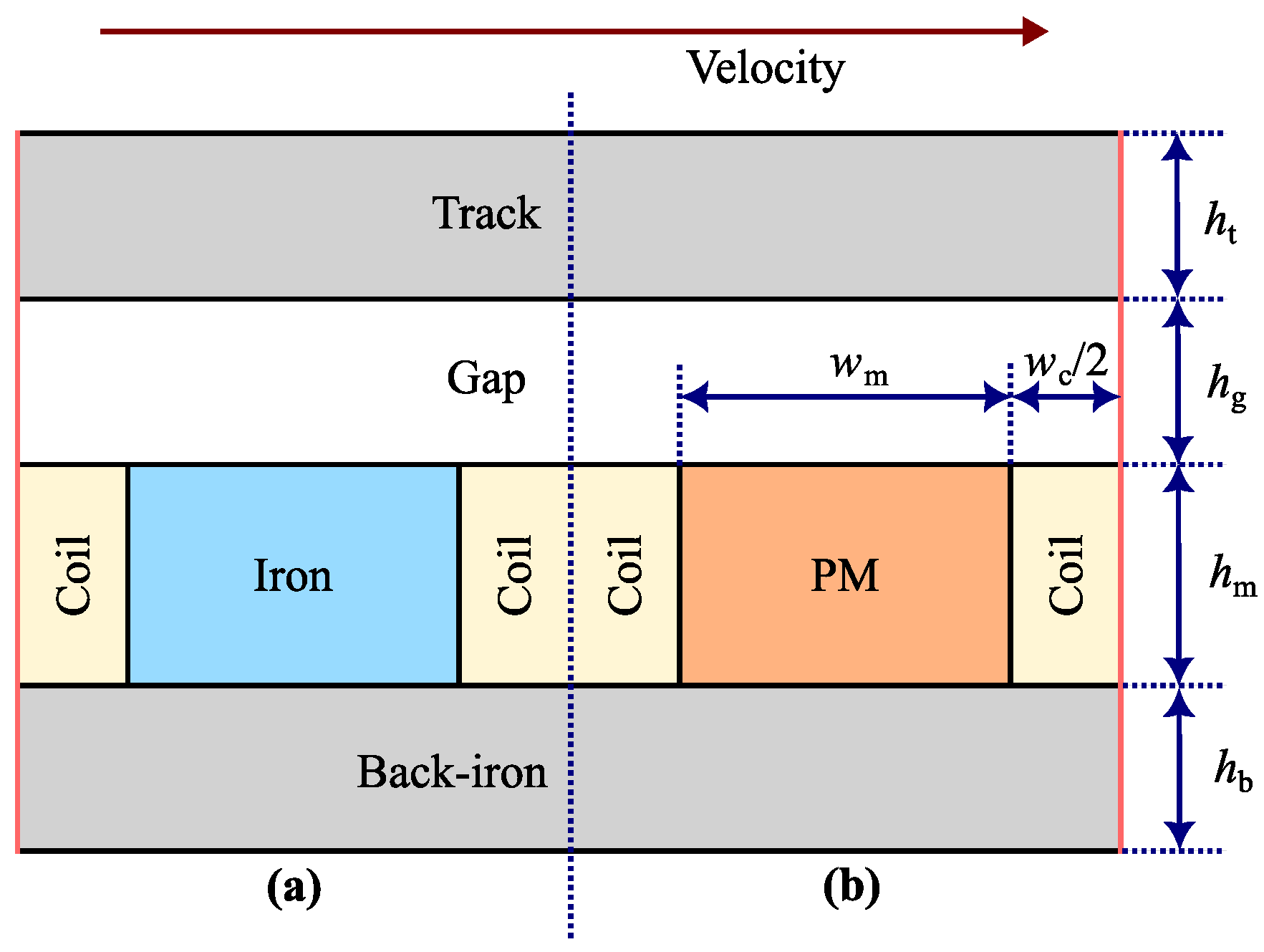
The levitation system—active or hybrid—is represented by an elementary module, which represents the most basic actuation unit for levitation purposes. This modular reduction allows for fast computations during the optimization process. Subsequently, the full levitation system can be constituted by multiple modules in parallel, according to the force requirements. The layout of both levitation module configurations is depicted in Figure 2. At the system level, bogies are installed with multiple levitation modules. For the hybrid case, the use of PMs with alternating polarity provides a force bias. For the active case, the back-iron is extended in place of the PMs to form the core. A bias current ensures levitation.
Physical and operational constraints such as overall system length and achievable positive stiffness of levitation magnets demand the definition of a suitable magnet geometry. Width w m and height h m are two crucial parameters for the magnets in the hybrid case and for the core in the active case. The total coil width w c strongly affects the positive stiffness. These parameters are set as optimization variables. Additionally, the out-of-plane thickness (or module length) L m is a variable parameter in the optimization.
The three objective functions defined for the optimization are
g 1 = 1 / F mod
g 2 = m tr + m lev
g 3 = 1 / k mod
where F mod denotes the module force in the vertical axis. The terms m tr and m lev refer to the mass of the track and the mass of levitated bodies, respectively. k mod denotes the positive magnetic stiffness of the module, computed as
k mod = F 1 F 2 z 1 z 2
where F 1 and F 2 refer to lift forces in extremum operating conditions ( p 1 and p 2 , respectively), reported in Table 1 for the two modules. The total gap deviation, z 1 z 2 , is used. For the hybrid case, control current density varies from J 1 = 9 A / mm 2 to J 2 = 9 A / mm 2 when the gap ranges from maximum to minimum. A flux-weakening action is imposed when the gap decreases. The bias current density for the active case is set at J b = 4 A / mm 2 to prevent thermal energy accumulation given a near-vacuum environment. Control current density varies from J 1 = 8 A / mm 2 to J 2 = 4 A / mm 2 when the gap ranges from maximum to minimum, adopting a differential driving scheme [25]. It is worth noting that these current density and air gap values represent extremum working points rather than stationary conditions. Nonetheless, the operation of the levitation system—even if transient—must be satisfied through all possible working points.
The cost function g 1 in Equation (1) targets the force capability of the module. The inverse of the force facilitates its minimization in the optimization. g 2 in Equation (2) aims at solutions that minimize overall module mass. g 3 in Equation (3) maximizes the positive stiffness of the module. As in Equation (1), the inversion allows for formulating a function to minimize it.
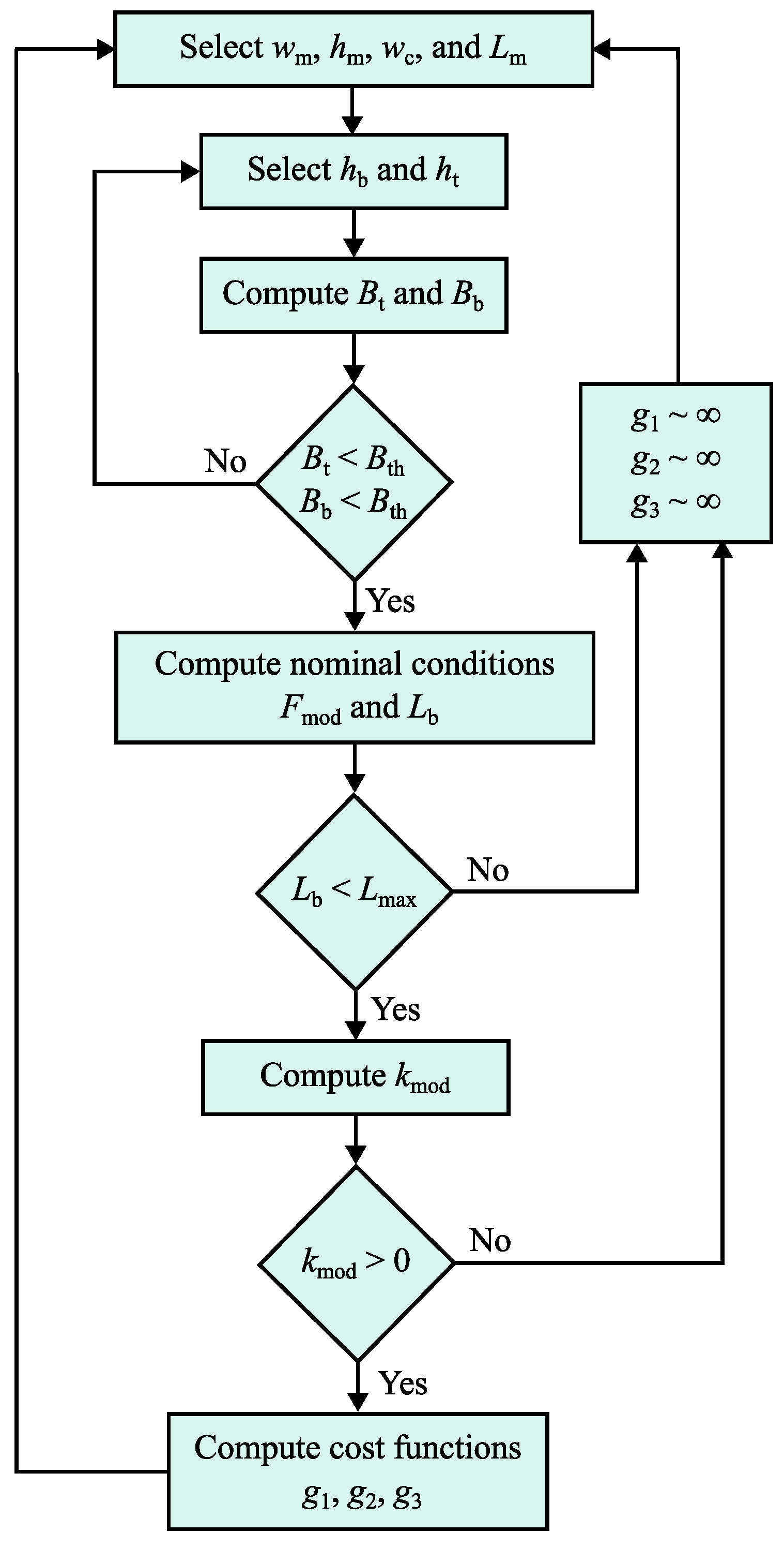
The optimized design of the modules requires several constraints, outlined in the following. The total length of the bogie L b is restricted to L max = 30 m when in nominal operating conditions. The force per module F mod is used to estimate the length of the bogie, knowing the mass to be levitated. An initial selection phase of back-iron height h b and track height h t is carried out at operating point p 1 in Table 1. The height is chosen such that the flux density in the track B t and flux density in the back-iron B b are limited to B th = 1.6 T . The flux density magnitude is computed and compared to the same threshold value B th in the core of the active case. The module stiffness is required to be strictly positive.
The flow diagram in Figure 3 summarizes the computation of the cost functions. Each optimization iteration involves a stationary finite-element simulation lasting approximately five seconds. Two-dimensional models were discretized with a triangular mesh of approximately five thousand elements, where the magnetic vector potential was represented with linear shape functions. The quality of the mesh was measured by an average skewness of 0.91 . Mesh independence tests were carried out with a refinement criterion of output force variation below 5 % . This configuration proved to be lightweight but accurate from a computational perspective.
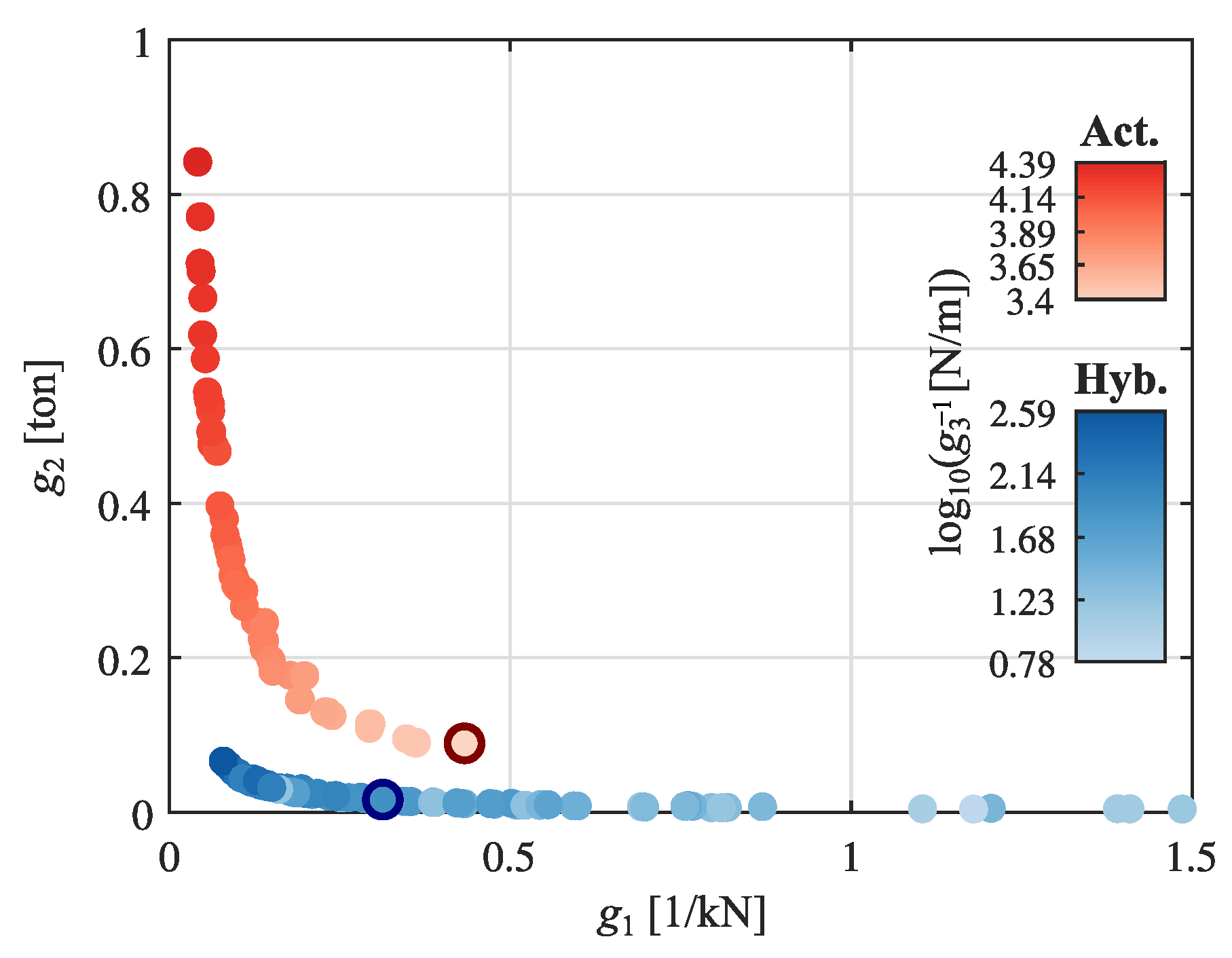
Pareto fronts of non-dominating solutions are extracted for the two cases, indicated in Figure 4. Blue points refer to hybrid module solutions, whereas red points refer to active module solutions. For the hybrid module, a solution is chosen prioritizing g 1 (levitation force) and g 2 (mass), keeping the value of g 3 (magnetic stiffness) to a minimum between possible selections. The choice is made observing that g 1 (levitation force) does not decrease significantly as desired when g 2 (mass) increases. The inverse is observed when reducing g 2 (mass), where g 1 (levitation force) increases undesirably. For the active case, the solution is chosen prioritizing g 2 (mass) to limit the size of the module. Levitation force ( g 1 ) is noted to be comparable with the hybrid case; however the range of externally applied current densities results in larger values of k mod compared to the hybrid module. Table 2 reports the dimensional bounds and selected configurations for both studied cases. Note that it is the designer’s choice to prioritize the cost functions for the selection of a configuration. Additionally, the results obtained highlight an out-of-plane thickness of the module ( L m ) that is at least three times larger than the magnet height ( h m ). These results confirm that the selection of a two-dimensional finite-element solution is sufficient for the purposes of this research, as the role of end effects can be neglected.
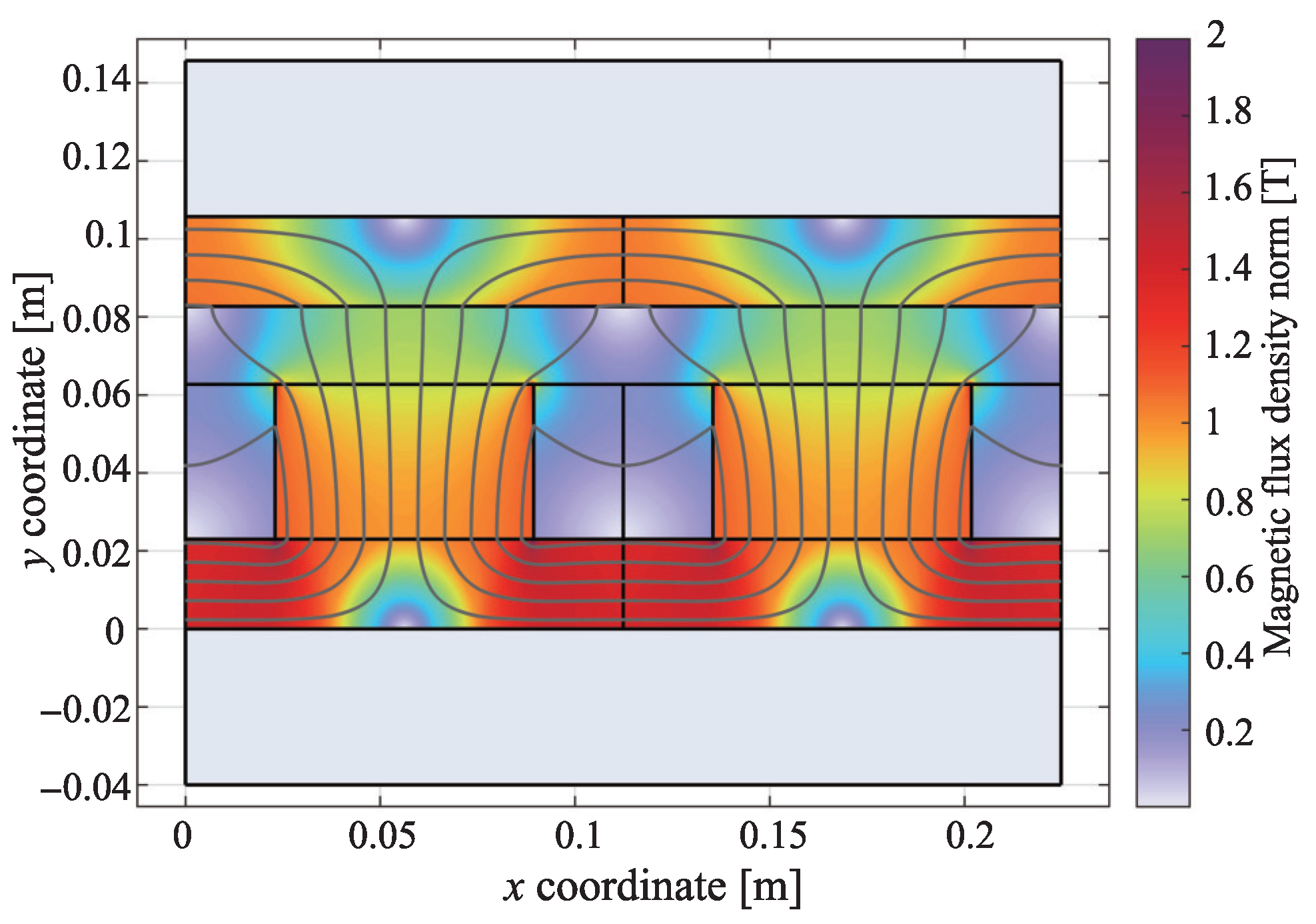
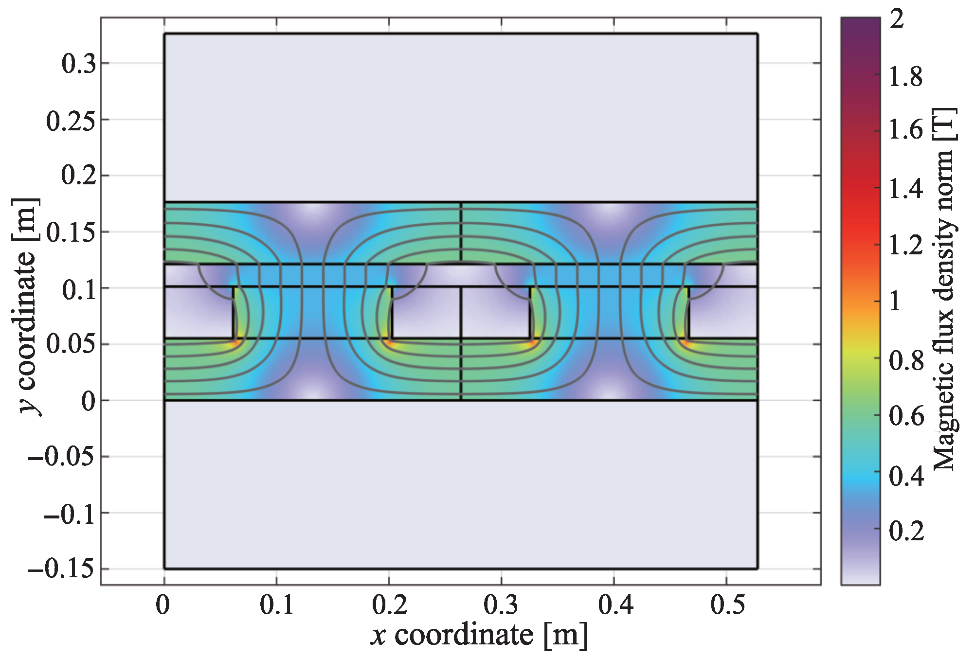
Considering a copper fill factor of 0.5 , the optimization produces a large geometry that satisfies the levitation requirement for the active case, limiting saturation under maximum gap conditions. The size difference between modules is indicated in Figure 5. The hybrid case benefits from the use of PMs, allowing for a comparatively compact solution. The magnitude of the magnetic flux density and distribution of the final configurations are reported in Figure 6 for the hybrid module and Figure 7 for the active module under nominal levitation conditions. Magnetic flux density magnitude affects eddy current and hysteresis losses. Adequate current density in the hybrid case is needed to account for a large magnetic flux density.

2.2. Losses and Magnetic Drag

A 2D COMSOL finite-element model is used in stationary conditions to output the magnetic flux distribution necessary for loss computation. The Bertotti iron loss model is used [26]. Specific losses are computed on the basis of three contributions: hysteresis, eddy currents, and anomalous terms. The track is discretized, and the magnetic flux density is computed along the coordinates of each segment. The Fast Fourier Transform (FFT) is applied to the magnetic flux density. The magnetic flux distribution is assumed to be the same along the depth of the module. The computation of these losses is outlined by
P loss = m strip q = 1 N s n = 1 N K h n B ^ x , n α f + K a ( n B ^ x , n f ) 1.5 + K e ( n B ^ x , n f ) 2 q
where K h is the hysteresis loss coefficient, K e the eddy current loss coefficient, and K a the anomalous loss coefficient. The hysteresis loss exponent is α . The mass of the discretized strip m strip scales the losses. The frequency f is dependent on the speed v and length of the module:
f = v 2 ( w m + w c )
The FFT of the magnetic flux density in the longitudinal direction (x) for each harmonic n is denoted as B ^ x , n . A total of N harmonics are evaluated for each segment. The contribution of each strip q is summed over a total of N s strips to give the total loss in the track P loss . Coefficients refer to M210-35A electrical steel. Table 3 summarizes the loss coefficients and computation data.

2.3. System-Level Integration

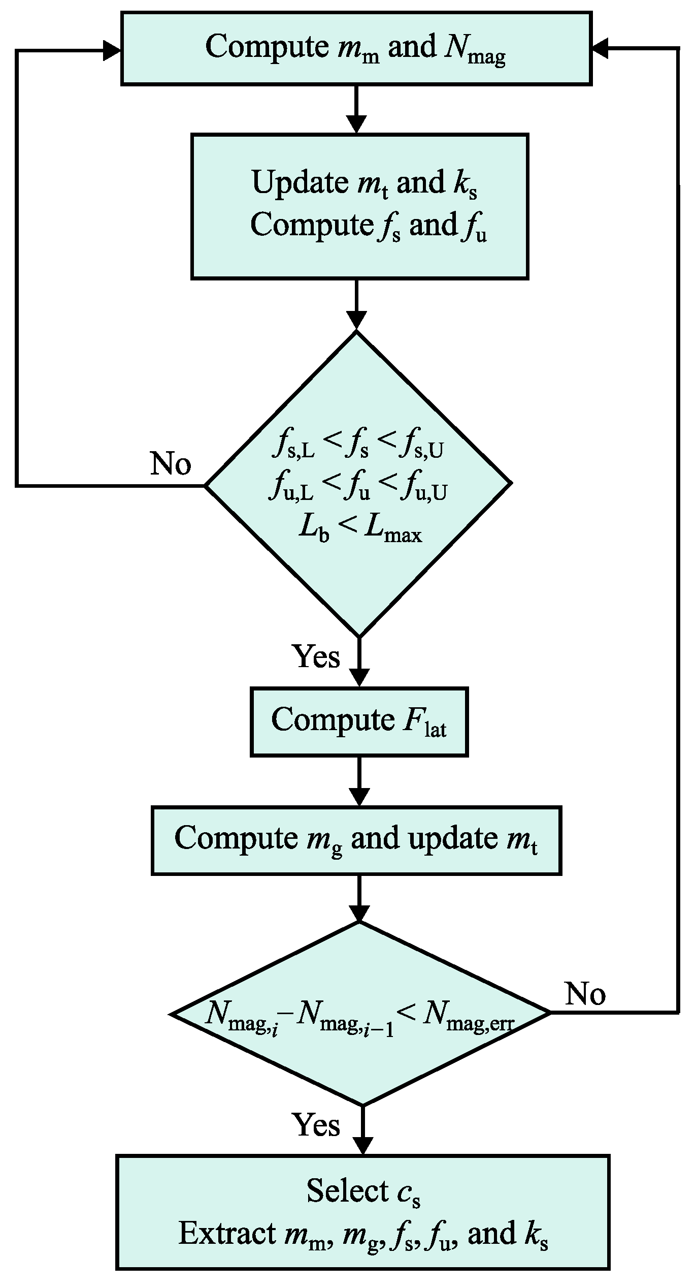
Magnetic drag losses represent a portion of the power consumption in this maglev system type. Gap control effort requires further power consumption due to the presence of disturbances. Control algorithm design requires a knowledge of overall mechanical system properties. The solution obtained at the component level is iteratively integrated into a complete capsule and bogie system, schematized in Figure 8. Additional magnet mass m m is computed based on the total number of levitation magnets N mag . Total mass m t and secondary suspension stiffness k s are evaluated. Frequency-domain behavior for vertical dynamics is subject to constraints. The sprung mass natural frequency f s and unsprung mass natural frequency f u are limited by upper and lower bounds, f k , U and f k , L , with k = s , u . These bounds ensure that f s < f u , guaranteeing proper decoupling of dynamics for both masses. Bogie length L b must satisfy a total length constraint L max = 30 m . Active lateral guidance electromagnets are assumed for both cases. Lateral guidance module number is computed assuming a banking condition with a static centrifugal force F lat incident on the system. The banking angle is assumed to be 6°, with a turn radius of 3 km and speed of 400 km / h . The additional mass m g due to the required number of lateral guidance modules is computed and m t is updated for the next iteration of levitation magnet mass computation. An exit condition for the integration loop is included, where the number of levitation magnets in the current iteration N mag , i is compared to that of the previous iteration N mag , i 1 against a predefined error N mag , err . Once complete, a suspension damping value c s is selected for adequate passive attenuation in the frequency domain. Note that auxiliary components, such as the onboard battery and propulsion system, are neglected.
Table 4 summarizes the main mechanical parameters at the system level for the two cases. Note that the additional mass introduced differs significantly between the two configurations. Larger active levitation modules augment the mass of the bogie. Available data in the literature is consulted regarding the sensibility of obtained mechanical features for the two cases. The percentage of levitation actuator mass with respect to total levitated mass is used as a comparison indicator. For the present active case, 16.8 % of the total levitated mass is composed of the levitation system. In [27], the system studied is based on the Shanghai Maglev, with 15.4 % of the levitated mass represented by the levitation system. Another study on a similar maglev vehicle indicates 20 % of the levitated mass reserved for the levitation system [28]. These metrics confirm that the obtained active case falls within reasonable mechanical limits. However, it is noted that constraints on capsule and bogie natural frequencies result in larger secondary suspension stiffness.

2.4. Control Strategy

The position controller is defined with proportional–integral–derivative (PID) control. The choice of parameters is made with the use of linear coefficients characterizing the actuators [25]. The coefficients are
K x = F x i c = 0
K i = F i z d = 0
where the force–displacement factor K x and force–current factor K i depend on the actuator force F. The behavior of force with respect to displacement at null control current ( i c = 0 ) is described in Equation (7). The behavior of the force with respect to the control current at null vertical displacement ( z d = 0 ) is described in Equation (8). K x is included in the state-space representation of the two-degree-of-freedom system, isolating vertical dynamics. It is also termed negative stiffness: force increases for a decreasing gap. The schematic in Figure 1 is used as a reference. A single input, single output system is defined, and the position controller is expressed as
G PID = P + I s + D N 1 + N / s
where P is the proportional gain, I the integral gain, and D the derivative gain. A closure pole factor N is included for the derivative term. The Laplace operator is denoted by s.
The proportional gain is defined by
P = ( 2 π f u ) 2 ( m b + m m + m g ) + K x N mag / 2 K i N mag / 2
where the added levitation magnet mass m m and lateral guidance magnet mass m g are summed with the bogie mass m b . The expression refers to an equivalent stiffness identified in the equation of motion of the bogie. A compensation of the negative stiffness K x is necessary to ensure stability. The proportional gain is tuned to attain the desired undamped bogie natural frequency in Table 4. The derivative and integral gains are tuned for an adequate attenuation of sprung and unsprung mass natural frequencies. Controller gains are summarized in Table 5.
The closed loop transfer function is
G CL = G PID K i N mag G sys / 2 1 + G PID K i N mag G sys / 2
where N mag is the levitation magnet number and G sys the mechanical system state space. The magnet number is halved, as each module is modeled with one magnet pole pair and K x and K i are calculated per module. Although the position controller should be cascaded with a current controller, the dynamics of the latter are not included in the closed-loop transfer function, assuming a sufficiently large bandwidth for current compensation.
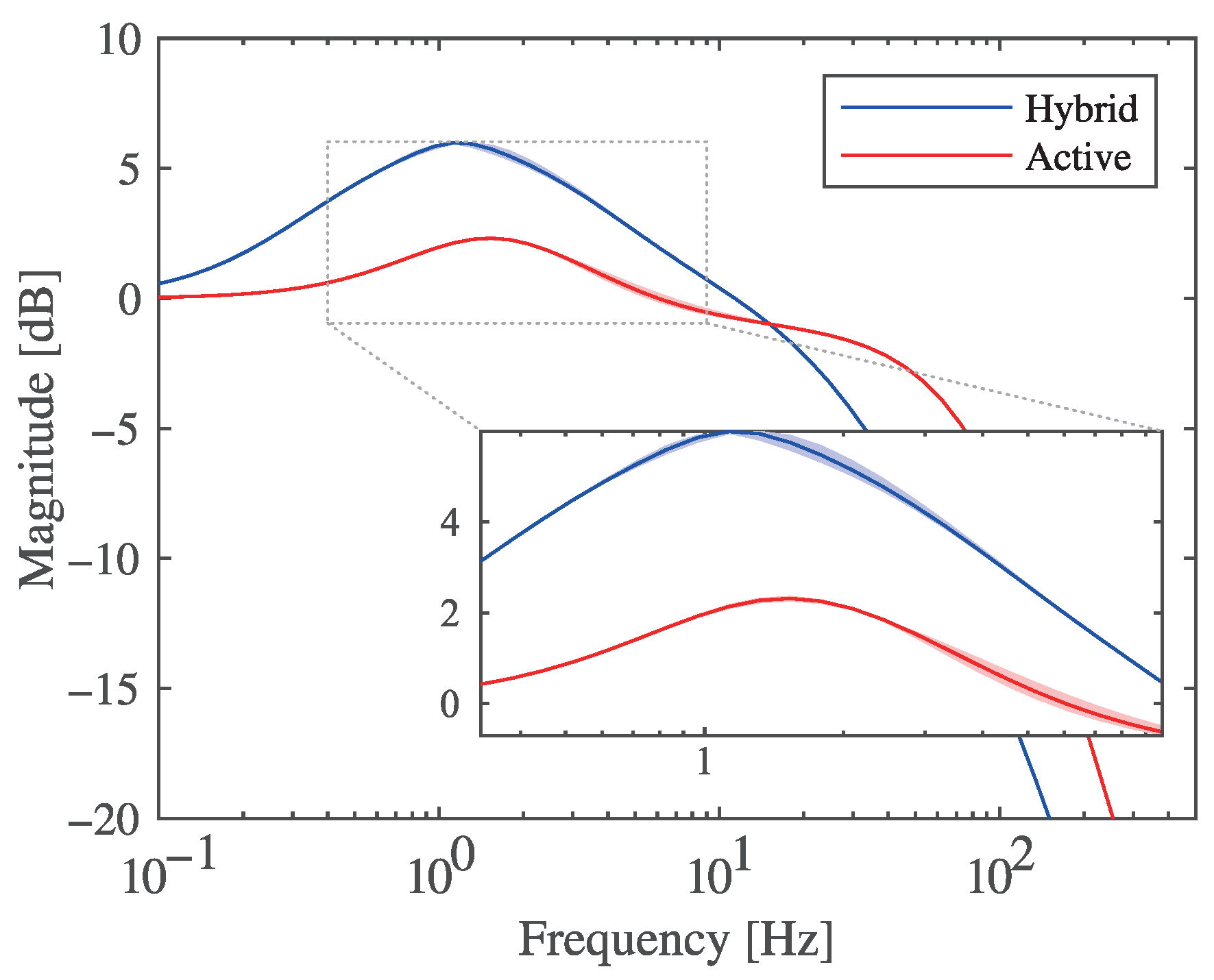
The corresponding frequency responses are shown in Figure 9. Although gains differ, closed-loop behavior in the frequency domain remains comparable. Controller parameters are selected on the basis of ensuring stable operation and suitable frequency-domain behavior. The use of PID control serves to outline a key aspect of maglev system design. A variation in capsule mass by ± 25 % forms an envelope delimiting the nominal response. It is estimated based on the upper bounds of passenger weight and a consideration of possible mass overestimation. In both hybrid and active cases, capsule mass variation is expected to have minimal impact on system dynamic behavior.
The position controller is implemented with a zero-power law. For quasi-static loads applied to the capsule or bogie, constant power dissipation is present if a fixed reference gap is imposed. This is mitigated by setting a variable gap reference. This is achieved by means of a proportional gain dependent on the linear coefficients of the actuators. Equation (12) indicates this modification as
P i = a i K i K x
where P i is the gain that converts a constant current consumption value to a constant displacement. The coefficient a i is used as a tuning factor.
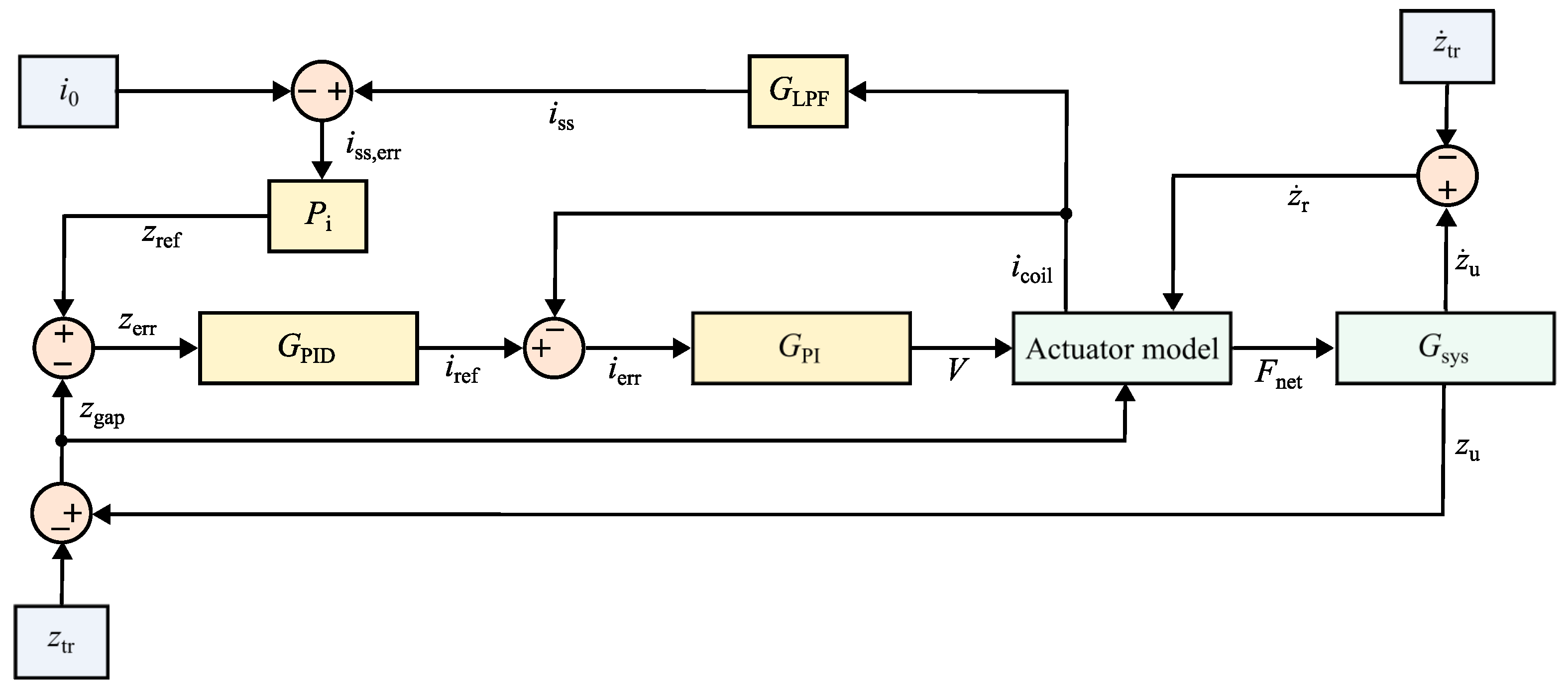
The synthesized controller is implemented in a Simulink model that exploits force, inductance, and induced back-EMF look-up tables as functions of gap and control current. Additional look-up tables characterizing the drag losses are functions of longitudinal speed, gap, and control current. They are populated with data from the already presented simulations in COMSOL Multiphysics. In this step, a current controller is included, featuring a relatively wide bandwidth of 1 kHz , preserving the assumption made during position controller synthesis. The current controller was tuned to compensate for the dynamics of the electromagnet impedance through zero-pole cancellation. Figure 10 indicates the full control scheme.
The coordinate z tr represents the track displacement profile, and the relative velocity is z ˙ r . Bogie displacement is z u and the term z gap is the gap compared to the reference displacement z ref . The displacement error z err is fed into the position controller to produce the reference current i ref that is compared with the coil current i coil . The current error is i err and is fed into the current controller G PI to produce the voltage command V. The actuator model outputs the net force on the bogie F net . The variable position reference depends on the coil current passing through a low-pass filter G LPF to isolate the steady-state current consumption i ss , which is compared with the null current setpoint i 0 . Finally, the steady-state current error i ss , err is scaled with the proportional gain in Equation (12).

2.5. Track Irregularities

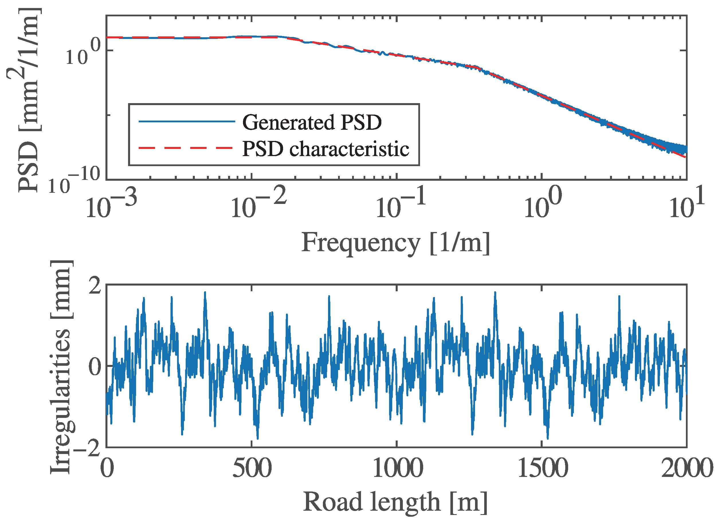
Track irregularities are a potential disturbance type expected by the system. To investigate the control effort at certain longitudinal velocities, a track irregularity profile is computed from the power spectral density (PSD) in Figure 11, based on a characterization in the literature [29]. The computation of the random track profile is carried out with a harmonic approach. Sinusoidal signals with amplitudes derived from the PSD are summed [30]. The PSD is scaled by a factor of 0.05 , giving a root-mean-square (RMS) displacement of z r , R M S = 0.6 mm , assuming tighter track machining tolerances.

3. Numerical Results

Power consumption due to magnetic drag and track irregularities is evaluated for the system with integrated levitation and guidance modules. Power consumption due to aerodynamic drag is assumed to be identical for both cases. The mechanical system state space, controllers, and actuator model are assembled in a Simulink time-domain model. Firstly, smooth track conditions are simulated to assess power offsetting magnetic drag. The steady-state levitation power in the active case is included. Secondly, control power due to track irregularities is studied. Although eddy current losses refer to propulsion power, and gap control effort refers to levitation power, the combination of the two contributions remains of interest assuming a unique onboard power source.
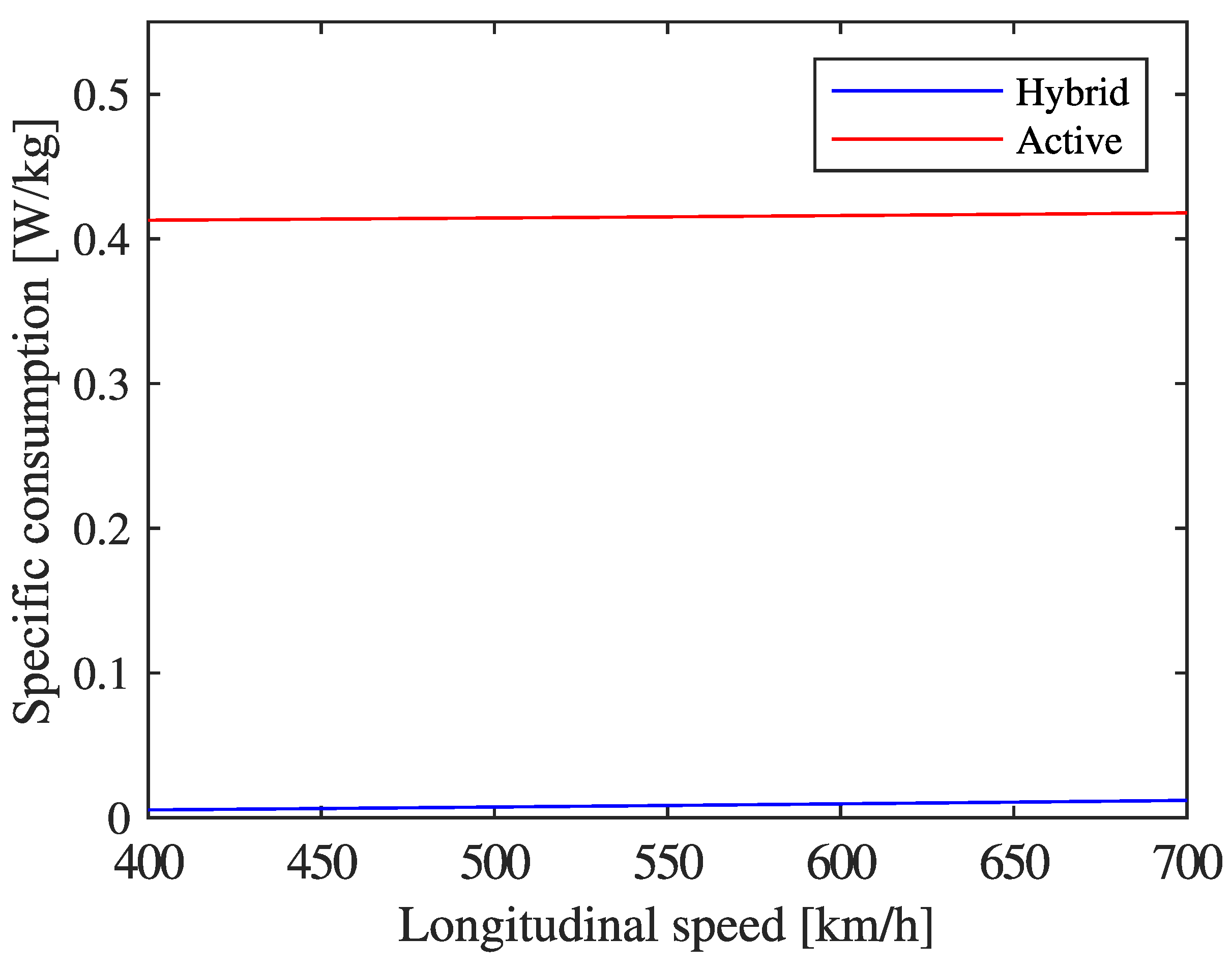
Simulations were run using an ode23t solver for stiff problems and an integration time step of 10 μ s . Figure 12 indicates the average specific consumption—power drawn per levitated kilogram—of one capsule for a speed range of 400–700 km/h in smooth track conditions. Magnetic drag power consumption is minimal due to the use of a laminated track, evidenced in the hybrid case. In the active case, much of the power is associated with levitation; however the request per kilogram is agreeable due to the large electromagnet size.
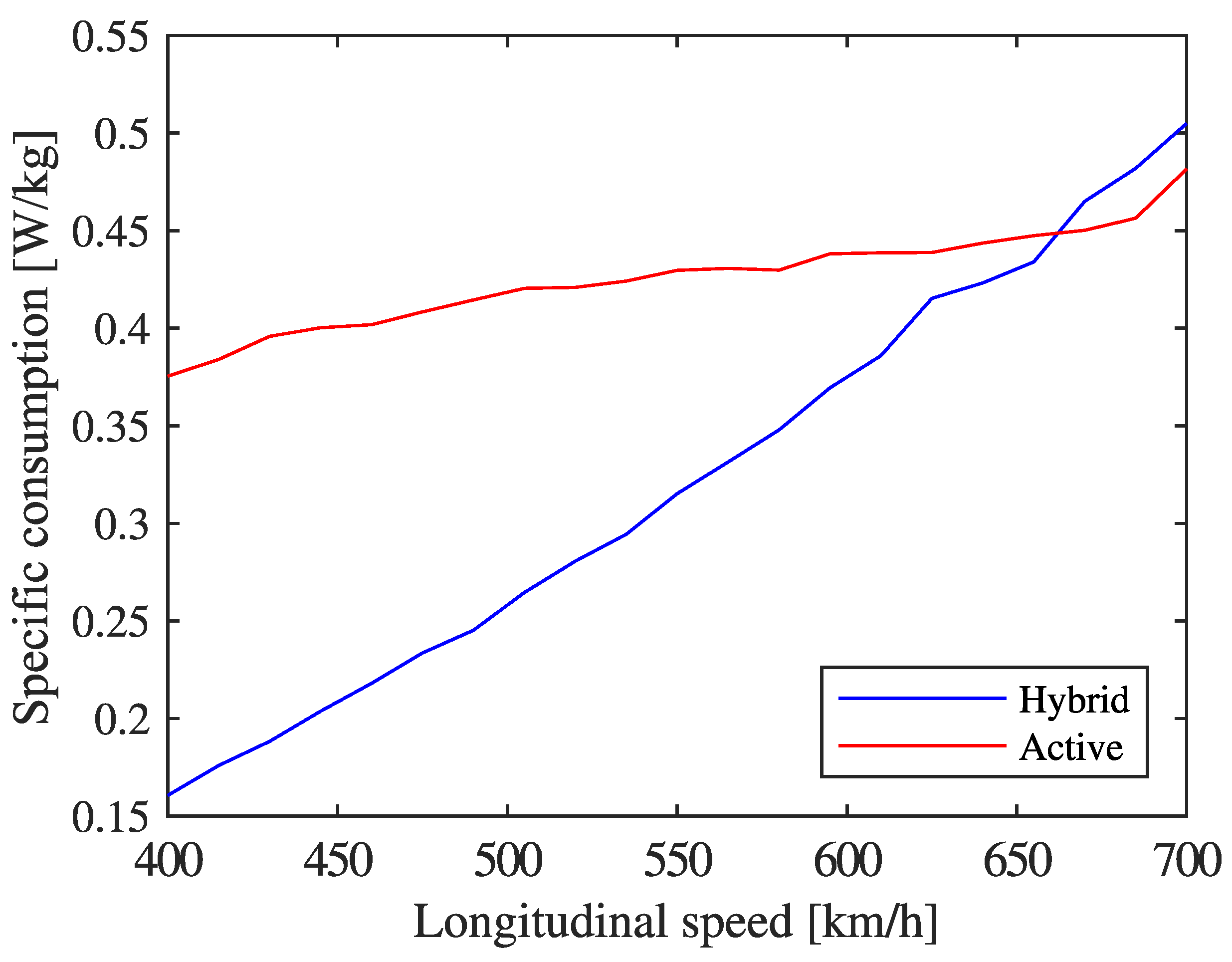
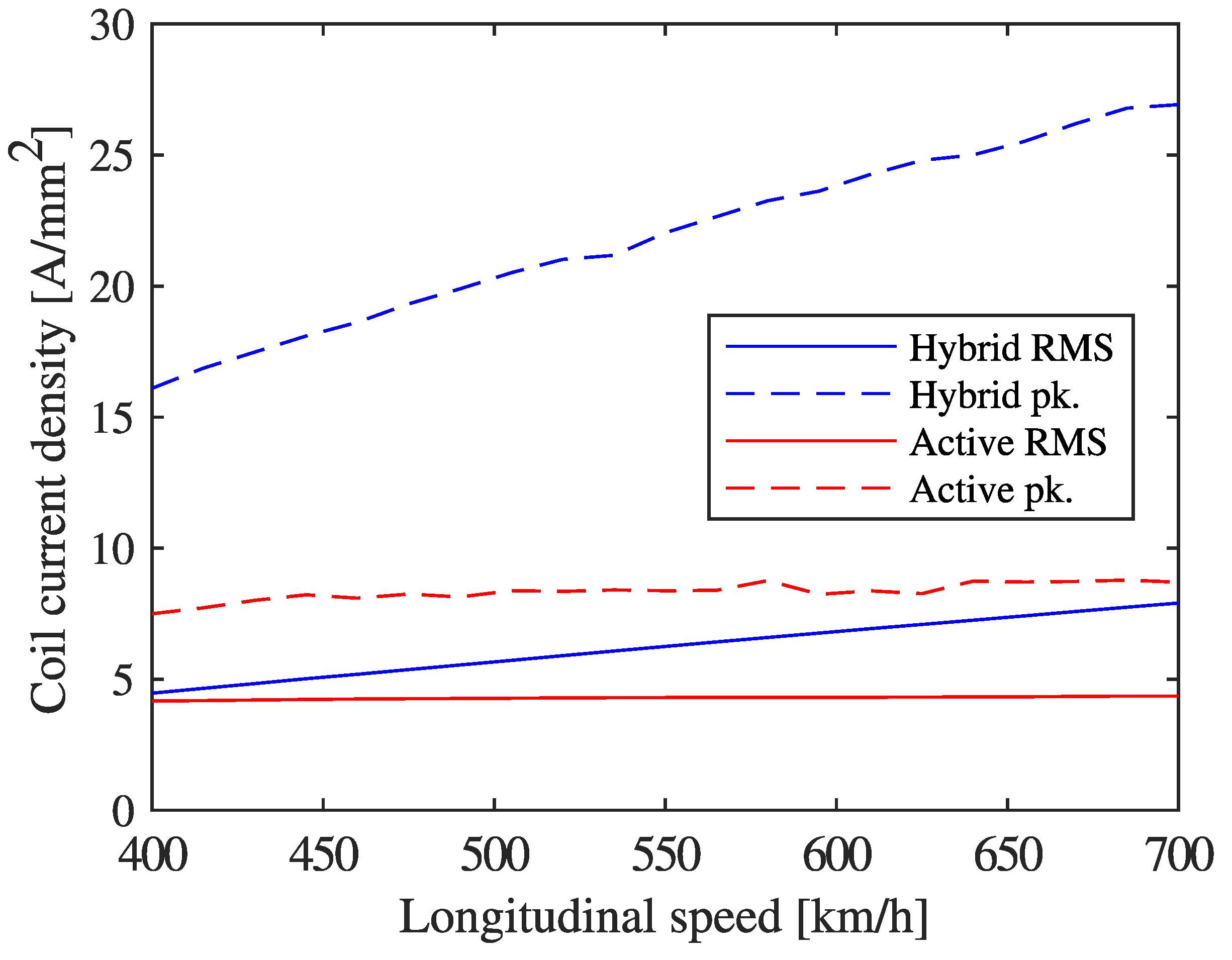
The presence of track irregularities demands a control effort due to a constant gap policy. The average specific consumption for both cases is reported in Figure 13 for the same speed range. Power request increases with speed as the temporal frequency of perturbations increases. The specific consumption of the hybrid case is noted to surpass that of the active case beyond a speed of 662 km / h . At a speed of 400 km / h , the specific consumption of the active case is approximately 2.3 times greater than in the hybrid case. Figure 14 outlines the RMS and peak current densities for both cases. The peak current density in the hybrid case is almost 3.1 times greater than in the active case for the maximum speed of 700 km / h . The duration of current peaks is sufficiently short, posing no threat of Joule loss damage. The RMS current density in the active case shows a slight linearly proportional variation across different speeds, with values ranging from 4.2 A / mm 2 to 4.4 A / mm 2 . Conversely, the hybrid setup starts with 4.5 A / mm 2 at 400 km / h and increases linearly up to 7.9 A / mm 2 at 700 km / h . Given vacuum conditions, accumulation of thermal energy may be critical. This drawback highlights the need for active cooling at high speed. The design and inclusion of a thermal management system go beyond the scope of this work; however, there exist several potential solutions. Cooling methods explored for rotating machines can be considered, such as coolant-carrying channels introduced at hotspots [31]. A dedicated heat exchange system is also needed on board to ensure adequate inlet coolant temperature.
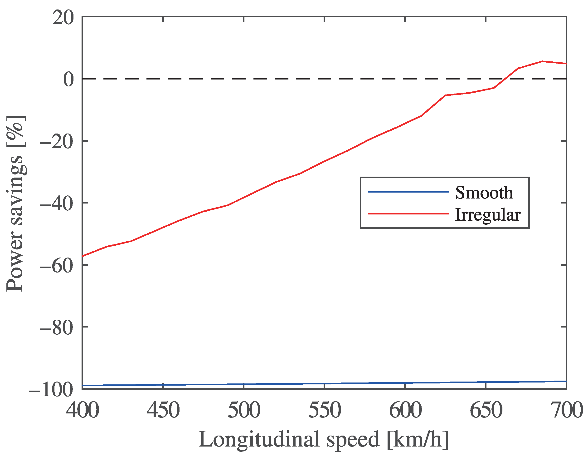
Figure 15 indicates the specific consumption savings for the hybrid case with respect to the active case. A negative value refers to a saving (reduction with respect to the active case). For smooth track conditions, a minimum specific consumption reduction of 97.6 % is achieved for the hybrid system when traveling at 700 km / h . The percentage reduction decreases with increasing speed as the hybrid case features a higher nominal magnetic flux density magnitude in the track, yielding greater losses. When track irregularities are included, the hybrid case consumes more power per kilogram beyond a speed of 662 km / h , requiring 5.6 % more specific consumption than the active case at a speed of 685 km / h . The maximum power reduction is achieved at 400 km / h with 57.2 %. Power reduction for the hybrid case with respect to the active case decreases when speed increases under irregular track conditions. This is attributed to the control effort required to manage the negative stiffness of the PMs in the hybrid case at higher-frequency perturbations.

4. Conclusions

The design approach for a heteropolar magnetic levitation system has been presented in the cases of hybrid and active configurations. The methodology can be extended to other levitation architectures. Component-level parameter selection for both module types is based on a Pareto front obtained through a multi-objective genetic algorithm optimization. Levitation modules are integrated into a capsule and bogie system, with adequate position controller design with respect to desired frequency-domain behavior. Power consumption due to eddy current losses is computed with the Bertotti approximation. The power to generate and control the magnetic field is considered in smooth and irregular track conditions for the two-degree-of-freedom system in a numerical validation.
The hybrid case outperforms the fully active case in specific consumption for a large part of the speed range. Average specific consumption in smooth track conditions is 97.6 % lower in the hybrid case compared to the active case for the maximum speed of 700 km / h . For lower speeds power savings are greater. In irregular track conditions, a benefit in specific consumption is observed up to a speed of 662 km / h . The maximum percentage reduction is 57.2 % at the minimum speed of 400 km / h .
Smaller hybrid levitation modules favor practical system-level integration. However, the hybrid system presents several drawbacks: magnets are at risk of adhering to the track in the case of control failure, and thermal management must be addressed to prevent PM demagnetization. These issues can be solved with further design considerations such as cooling system development and flux weakening to prevent or reverse PM–track adherence.
Further work involves the characterization of hybrid homopolar levitation modules where the magnetic circuit is transverse to the track. Moreover, the optimization approach may be extended to the lateral guidance system. A comparison can be made between homopolar and heteropolar magnet systems with regard to magnetic drag. Indeed, a homopolar arrangement does not require a laminated track as the magnetic flux density variation is minimal along the length of the pad. An experimental validation of the drag loss modeling approach is necessary for both heteropolar and homopolar arrangements. The development of a thermal management system remains an important aspect to ensure the technology’s feasibility. Addressing the risk of PM–track adherence in the hybrid case is also a focus of future work. Indeed, independent control and actuation of levitation modules guarantee lift compensation in the event of module failure. The inclusion of skids on PMs also allows for smaller flux-weakening current densities in the event of PM–track adherence.

Author Contributions

Conceptualization, A.T., M.P., R.G., N.A. and S.O.; methodology, A.T., M.P., R.G. and N.A.; software, M.P. and R.G.; validation, M.P.; formal analysis, M.P. and R.G.; investigation, M.P.; resources, A.T. and N.A.; data curation, M.P.; writing—original draft preparation, M.P. and R.G.; writing—review and editing, A.T., N.A. and S.O.; visualization, M.P. and R.G.; supervision, A.T., N.A. and S.O.; project administration, A.T.; funding acquisition, A.T. All authors have read and agreed to the published version of the manuscript.

Funding

This research received no external funding.

Institutional Review Board Statement

Not applicable.

Informed Consent Statement

Not applicable.

Data Availability Statement

The original contributions presented in this study are included in the article. Further inquiries can be directed to the corresponding author.

Acknowledgments

The authors would like to thank the team at HyperloopTT, who have been a close collaborator in the scope of this study.

Conflicts of Interest

Sofiane Ouagued was employed by the company SAS HYPERLOOP TT FRANCE. The remaining authors declare that the research was conducted in the absence of any commercial or financial relationships that could be construed as a potential conflict of interest.

Abbreviations

The following abbreviations are used in this manuscript:
EEnd-winding
EDSElectrodynamic suspension
EMFElectromotive force
EMSElectromagnetic suspension
FFTFast Fourier transform
LGELateral guidance electromagnet
PMPermanent magnet
PIDProportional integral derivative
PSDPower spectral density
RMSRoot-mean-square

References

  1. Galluzzi, R.; Circosta, S.; Amati, N.; Tonoli, A.; Bonfitto, A.; Lembke, T.A.; Kertész, M. A Multi-domain Approach to the Stabilization of Electrodynamic Levitation Systems. J. Vib. Acoust. 2020, 142, 061004. [Google Scholar] [CrossRef]
  2. Tramacere, E.; Pakštys, M.; Galluzzi, R.; Amati, N.; Tonoli, A.; Lembke, T.A. Modeling and experimental validation of electrodynamic maglev systems. J. Sound Vib. 2024, 568, 117950. [Google Scholar] [CrossRef]
  3. Pakštys, M.; Delfarah, K.; Galluzzi, R.; Tramacere, E.; Amati, N.; Tonoli, A. Damping allocation and comfort-oriented suspension control for electrodynamic maglev systems. J. Sound Vib. 2025, 618, 119311. [Google Scholar] [CrossRef]
  4. Zhang, Z.; Shang, C.; She, L.; Chang, W.; Zhang, L. Structural optimal design of a permanent-electro magnetic suspension magnet for middle-low-speed maglev trains. IET Electr. Syst. Transp. 2011, 1, 61–68. [Google Scholar] [CrossRef]
  5. Zhao, C.; Oka, K.; Sun, F.; Harada, A.; Jin, J.; Zhang, M. Design of Zero-Power Control Strategy with Resisting Tilt of Hybrid Magnetic Levitation System. IEEE Trans. Ind. Electron. 2022, 69, 11394–11402. [Google Scholar] [CrossRef]
  6. Li, Y.; Dai, C.; Hu, R.; Li, X. Levitation control technology for high-speed maglev trains of PEM hybrid levitation. In Proceedings of the 2024 36th Chinese Control and Decision Conference (CCDC), Xi’an, China, 25–27 May 2024; pp. 5384–5389. [Google Scholar] [CrossRef]
  7. Afshar, K.K.; Javadi, A. Mass estimation and adaptive output feedback control of nonlinear electromagnetic levitation system. J. Sound Vib. 2021, 495, 115923. [Google Scholar] [CrossRef]
  8. Wang, M.; Hao, Z.; He, Y.; Zeng, S.; Qi, Z.; Liu, P. Active Disturbance Rejection Backstepping Cross-Coupling Controller Design for a Magnetic Levitation Vehicle Suspension Frame. IEEE Trans. Transp. Electrif. 2024, 11, 4634–4644. [Google Scholar] [CrossRef]
  9. Najafi, A.; Mobayen, S.; Rouhani, S.H.; Mokhtare, Z.; Jalilvand, A.; Fridman, L.; Su, C.L. Robust Adaptive Fault-Tolerant Control for MAGLEV Train Systems: A Non-Singular Finite-Time Approach. IEEE Trans. Transp. Electrif. 2024, 11, 3680–3690. [Google Scholar] [CrossRef]
  10. Ni, F.; Mu, S.; Kang, J.; Xu, J. Robust Controller Design for Maglev Suspension Systems Based on Improved Suspension Force Model. IEEE Trans. Transp. Electrif. 2021, 7, 1765–1779. [Google Scholar] [CrossRef]
  11. Jiang, S.; Xu, H.; Zhang, T.; Yao, X.; Long, Z. Lazy Prescribed-Time Synchronization Control of Half Bogie for High-Speed Maglev Train Considering Track Irregularities and Input Constraints. IEEE Trans. Veh. Technol. 2022, 71, 6924–6937. [Google Scholar] [CrossRef]
  12. Lv, G.; Cui, L.; Zhi, R.; Zhang, Z. Characteristic Analysis of Improved Transverse Flux Linear Synchronous Motor Integrated Propulsion, Levitation and Guidance for Maglev Train. IEEE Trans. Veh. Technol. 2023, 72, 11428–11436. [Google Scholar] [CrossRef]
  13. Schiefer, P.; Kleikemper, O.; Holzapfel, F. Modeling of Coupled Electric and Magnetic Circuits in Electromagnetic Suspension Vehicles. IEEE Trans. Transp. Electrif. 2025, 11, 648–655. [Google Scholar] [CrossRef]
  14. Tudor, D.; Paolone, M. Optimal Design of the Propulsion System of a Hyperloop Capsule. IEEE Trans. Transp. Electrif. 2019, 5, 1406–1418. [Google Scholar] [CrossRef]
  15. Tudor, D.; Paolone, M. Operational-driven optimal-design of a hyperloop system. Transp. Eng. 2021, 5, 100079. [Google Scholar] [CrossRef]
  16. Lai, Q.; Liu, J.; Haghani, A.; Meng, L.; Wang, Y. Energy-efficient speed profile optimization for medium-speed maglev trains. Transp. Res. Part E Logist. Transp. Rev. 2020, 141, 102007. [Google Scholar] [CrossRef]
  17. Zhai, D.; Lai, X.; Meng, J.; Liu, G.; Wu, J.; Xiao, S. The Hybrid Suspension System for Middle-to-Low-Speed Maglev Trains Considering the Prevention of Firm Absorption. IEEE Trans. Transp. Electrif. 2022, 8, 1482–1492. [Google Scholar] [CrossRef]
  18. Gao, T.; Yang, J.; Jia, L.; Deng, Y.; Zhang, W.; Zhang, Z. Design of New Energy-Efficient Permanent Magnetic Maglev Vehicle Suspension System. IEEE Access 2019, 7, 135917–135932. [Google Scholar] [CrossRef]
  19. Demicoli, J.; Kleikemper, O.; Steinhorst, S. Systematic Optimization of Electromagnet Hardware for Electromagnetic Suspension: A Fusion of Simulation and Multi-objective Optimization Techniques. IEEE Trans. Magn. 2024, 60, 1–5. [Google Scholar] [CrossRef]
  20. Tomczuk, B.; Wajnert, D. Field–circuit model of the radial active magnetic bearing system. Electr. Eng. 2018, 100, 2319–2328. [Google Scholar] [CrossRef]
  21. Wajnert, D.; Tomczuk, B. Two Models for Time-Domain Simulation of Hybrid Magnetic Bearing’s Characteristics. Sensors 2022, 22, 1567. [Google Scholar] [CrossRef]
  22. Li, X.; Palazzolo, A.; Wang, Z. A Combination 5-DOF Active Magnetic Bearing for Energy Storage Flywheels. IEEE Trans. Transp. Electrif. 2021, 7, 2344–2355. [Google Scholar] [CrossRef]
  23. Xu, S.; Sun, J.; Ren, H. An Active Magnetic Bearing With Controllable Permanent-Magnet Bias Field. IEEE/ASME Trans. Mechatronics 2022, 27, 3474–3481. [Google Scholar] [CrossRef]
  24. Zhang, W.; Wang, J.; Li, A.; Xiang, Q. Multiphysics Fields Analysis and Optimization Design of a Novel Saucer-Shaped Magnetic Suspension Flywheel Battery. IEEE Trans. Transp. Electrif. 2024, 10, 5473–5483. [Google Scholar] [CrossRef]
  25. Chiba, A.; Fukao, T.; Ichikawa, O.; Oshima, M.; Takemoto, M.; Dorrell, D.G. Magnetic Bearings and Bearingless Drives; Elsevier: Amsterdam, The Netherlands, 2005. [Google Scholar]
  26. Bertotti, G. Hysteresis in Magnetism; Academic Press: San Diego, CA, USA, 1998. [Google Scholar]
  27. Wang, J.; Jin, X.; Cao, Y.; Du, X. Numerical Simulation of High-Speed Maglev Vehicle-Guideway-Tunnel-Soil System. Int. J. Comput. Methods Eng. Sci. Mech. 2012, 13, 93–107. [Google Scholar] [CrossRef]
  28. Yang, P.; Sun, Y.; Luo, Y.; Ou, H. Stability Simulation and Analysis of Maglev Vehicle at Different Speed Based on UM. Mechatronics Intell. Transp. Syst. 2023, 2, 42–52. [Google Scholar] [CrossRef]
  29. Zhao, C.; Zhai, W. Maglev Vehicle/Guideway Vertical Random Response and Ride Quality. Veh. Syst. Dyn. 2002, 38, 185–210. [Google Scholar] [CrossRef]
  30. Rill, G. Road Vehicle Dynamics, 1st ed.; CRC Press: Boca Raton, FL, USA, 2011. [Google Scholar] [CrossRef]
  31. Aguilar-Zamorate, I.S.; Pakštys, M.; Galluzzi, R.; Ibarra, L.; Amati, N. Comparison of four liquid-cooling strategies for in-wheel motors. In Proceedings of the 2024 International Symposium on Electromobility (ISEM), Guadalajara, Mexico, 18–20 September 2024; pp. 1–7. [Google Scholar] [CrossRef]
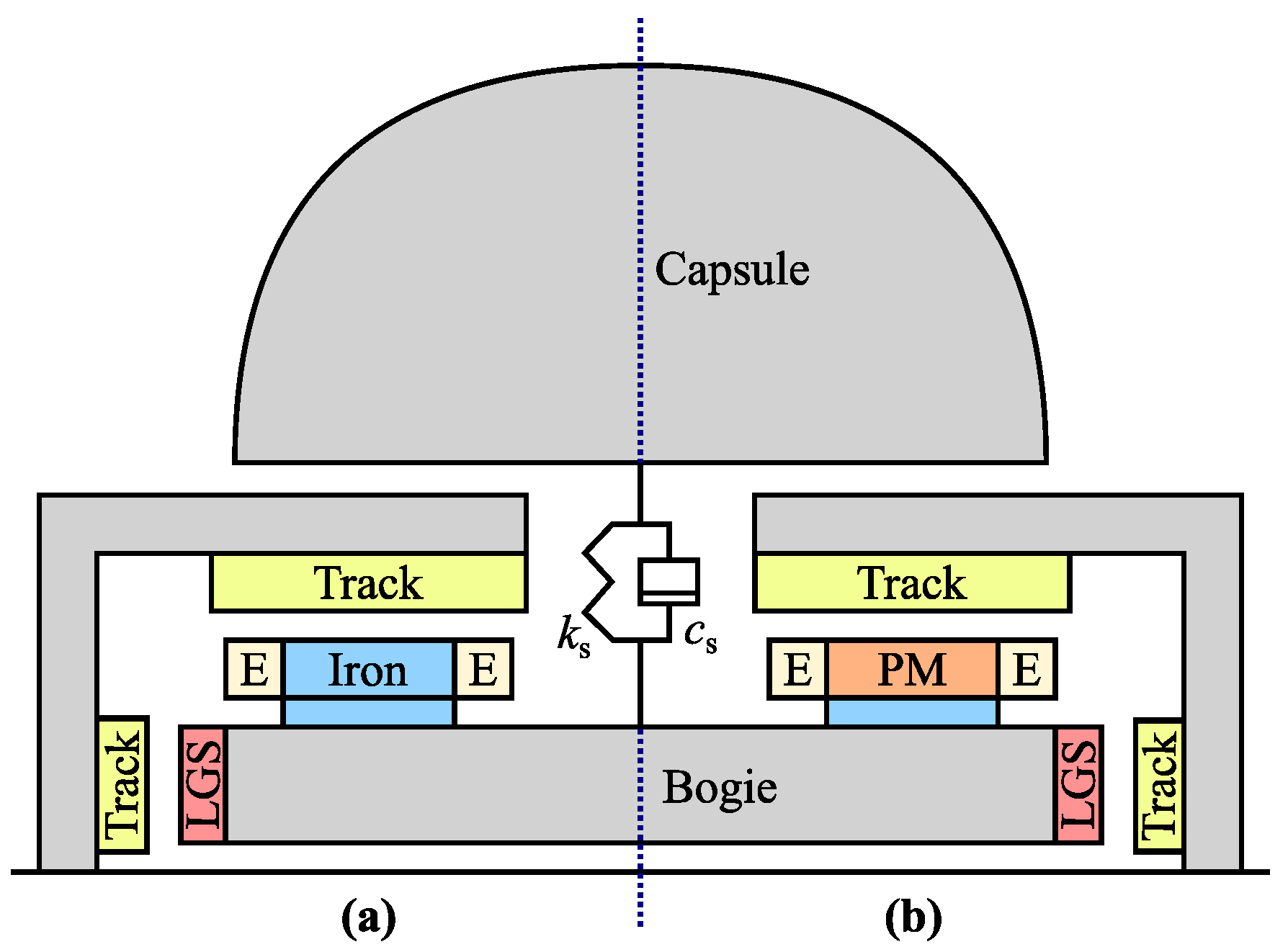
Figure 1. (a) Active maglev system consisting of an iron core, windings (not visible), and end-windings (E). (b) Hybrid maglev system consisting of permanent magnets (PM), windings (not visible), and end-windings (E). A back-iron is included. The capsule and bogie are connected with a secondary suspension characterized by stiffness k s and viscous damping c s . Lateral guidance electromagnets (LGS) ensure lateral stability. The track is laminated and longitudinal speed is out of plane. The tube is omitted for simplicity.
Applsci 15 09793 g001
Figure 2. (a) Active levitation module geometry in the x z plane consisting of iron core and coils. (b) Hybrid levitation module geometry in the x z plane. Boundaries marked in red represent periodicity conditions for the magnetic pole pair. Track height h t and back-iron height h b are selected within the optimization. Gap height h g is constant. Total coil width w c , magnet width w m , and magnet height h m are degrees of freedom in the optimization.
Applsci 15 09793 g002
Figure 3. Levitation module optimization procedure. In the active case, the core magnetic flux density must satisfy B th 1.6 T . Involved variables: magnet width w m , height h m , and out-of-plane thickness L m ; coil width w c , back-iron height h b , and track height h t ; flux densities in the track B t and back-iron B b ; and module force F mod , total bogie length L b , threshold bogie length L max , and module magnetic stiffness k mod . Cost functions: g 1 targets module force capability, g 2 represents overall module mass, and g 3 is the positive magnetic stiffness.
Applsci 15 09793 g003
Figure 4. Two-dimensional Pareto fronts for both modules. Points in blue refer to solutions for the hybrid module. Points in red refer to solutions for the active module. Cost functions relate to the inverse of the module force ( g 1 ), its mass ( g 2 ), and the inverse of its positive magnetic stiffness ( g 3 ). Selected solutions are circled for each case.
Applsci 15 09793 g004
Figure 5. (a) Hybrid module section view. Orange sections denote PMs. Grey sections denote the back-iron or track. (b) Active module section view. Blue sections denote the core (iron). Grey sections denote the back-iron or track.
Applsci 15 09793 g005
Figure 6. Magnetic flux density magnitude and distribution for hybrid case in nominal levitation conditions.
Applsci 15 09793 g006
Figure 7. Magnetic flux density magnitude and distribution for active case in nominal levitation conditions.
Applsci 15 09793 g007
Figure 8. Integration procedure of levitation and guidance modules into maglev system. Involved variables: levitation system mass m m , total number of magnets N mag , total mass m t , secondary suspension stiffness k s , capsule natural frequency f s , bogie natural frequency f u , and natural frequency upper bound f k , U and lower bound f k , L , with k = s , u ; static centrifugal force F lat , guidance system mass m g , and number of levitation magnets in the current iteration N mag , i and previous iteration N mag , i 1 ; and exit condition error N err , i and secondary suspension damping c s .
Applsci 15 09793 g008
Figure 9. Closed-loop transfer function G CL for hybrid (blue) and active (red) cases. An envelope for each transfer function is included based on a variation of ± 25 % in the capsule mass.
Applsci 15 09793 g009
Figure 10. Control logic of the maglev system. Involved variables: track displacement z tr and relative velocity z ˙ r ; bogie displacement z u , gap z gap , reference displacement z ref , displacement error z err , reference current i ref , coil current i coil , current error i err , current controller G PI , voltage V, net force on the bogie F net , low-pass filter G LPF , steady-state current i ss , null current setpoint i 0 , and steady-state current error i ss , err .
Applsci 15 09793 g010
Figure 11. Power spectral density (PSD) of track irregularities. Track irregularity profile over a 2 km length is generated by summing sinusoidal signals with amplitudes computed from the PSD.
Applsci 15 09793 g011
Figure 12. Average specific consumption (power drawn per levitated kilogram) in smooth track conditions over a speed range. An increase in specific consumption is noted for increasing speed due to increasing magnetic losses. An offset for the active case accounts for the bias coil current.
Applsci 15 09793 g012
Figure 13. Average specific consumption (power drawn per levitated kilogram) due to magnetic drag and random track irregularities over a speed range. Specific consumption increases for both modules as irregularity frequency increases. The hybrid case requires more specific consumption than the active case beyond a speed of 662 km / h .
Applsci 15 09793 g013
Figure 14. Coil current density in irregular track conditions over a speed range. Peak and RMS quantities are reported. A steeper increase in both peak and RMS current densities for the hybrid case indicates a greater control effort in managing PM negative stiffness.
Applsci 15 09793 g014
Figure 15. Specific consumption reduction for hybrid case with respect to active case over a speed range. Significant power savings shown for smooth track conditions. Savings decrease for increasing speed in irregular track conditions due to greater control effort.
Applsci 15 09793 g015
Table 1. Operating conditions for hybrid and active modules used for optimization.
Operating PointGap [mm]Current Density [ A / mm 2 ]
HybridActive *
p 1 (extremum point 1)2398
p 2 (extremum point 2)17 9 4
* Bias current density in the active module is J b = 4 A / mm 2 .
Table 2. Parameters obtained in multi-objective optimization of levitation module.
Dimension *SymbolHybridActive
LowerUpperOptimalLowerUpperOptimal
Magnet height h m 20100 39.7 20400 46.1
Magnet/tooth width w m 20100 66.4 20100 141.6
Total coil width w c 10504610200 122.4
Out-of-plane thickness L m 10300 121.7 10300147
Back-iron height h b 565237420 55.2
Track height h t 565237420 55.2
* All dimensions in mm .
Table 3. Bertotti loss model data and material coefficients for M210-35A electrical steel.
ParameterSymbolValueUnit
Hysteresis loss coefficient K h 4.7 mWskg 1 T α
Eddy current loss coefficient K e 2 mWs 2 kg 1 T 2
Anomalous loss coefficient K a 2.28 μ Ws 1.5 kg 1 T 1.5
Hysteresis loss exponent α 3.701
Number of harmonicsN10
Number of strips N s 100
Table 4. Parameters obtained during the sizing of heteropolar maglev systems.
ParameterSymbolValueUnit
HybridActive
Total number of magnets N mag 216200
Levitation system mass m m 12725578 kg
Guidance system mass m g 17112631 kg
Capsule mass m c 2020 ton
Bogie mass m b 55 ton
Capsule nat. freq. f s 1 1.45 Hz
Bogie nat. freq. f u 4.4 12.8 Hz
Capsule nat. freq. lower bound f s , L 0.85 0.85 Hz
Capsule nat. freq. upper bound f s , U 22 Hz
Bogie nat. freq. lower bound f u , L 44 Hz
Bogie nat. freq. upper bound f u , U 8.2 15 Hz
Secondary susp. stiffness k s 0.99 1.69 MN / m
Secondary susp. damping c s 150600 kNs / m
Table 5. PID gains for hybrid and active systems.
ParameterSymbolValueUnit
HybridActive
Proportional gainP 35.99 5.41 kA / m
Integral gainI5020 kA / ms
Derivative gainD900300 As / m
Closure pole factorN 10 3 10 3
Disclaimer/Publisher’s Note: The statements, opinions and data contained in all publications are solely those of the individual author(s) and contributor(s) and not of MDPI and/or the editor(s). MDPI and/or the editor(s) disclaim responsibility for any injury to people or property resulting from any ideas, methods, instructions or products referred to in the content.