Abstract
A significant aerodynamic interference effect exists between parallel bridges. In this study, a proposed long-span cable-stayed bridge, near which is an existing truss-arch bridge, was considered as the background. The wind characteristics at the proposed bridge site and the wind-induced responses of the bridge deck were investigated with and without the influence of an upstream bridge. The results showed that under aerodynamic interference of the upstream bridge, the downstream bridge site exhibited a noticeable change in the mean wind speed profile within the height range of the main girder and arch. The turbulence intensities significantly increased, especially for u and w components. The integral scales decreased remarkably, and the wind speed spectra redistributed toward higher frequencies. For the wind-induced responses, the mean displacements of the downstream bridge all decreased; in contrast, the buffeting and peak displacements all increased in both the maximum single cantilever state and the completed state, while the variation in buffeting response was much more significant and dominated the peak response. Moreover, under the interference of the upstream bridge, the buffeting displacement spectra redistributed toward high frequencies. This research acts as an effective tool for achieving secure bridge design and finding a better balance between design constraints.
1. Introduction
The span of cable-supported bridges has increased with the development of design and construction techniques. Accordingly, bridges are becoming more flexible and more sensitive to wind excitation. Owing to the high cost of demolition and rebuilding, numerous bridges have been built close to pre-existing bridges to accommodate the growth in traffic volume in recent years. However, most previous studies have focused on wind-induced vibration and control associated with single bridges. Adopting the results of these studies will cause bias in the calculation of wind resistance of downstream bridges under the aerodynamic interference of neighboring bridges, which is not conducive to the accurate assessment of structural wind-resistant stability.
The planning of parallel bridges requires a more in-depth study of the interference effects between neighboring structures than usual [1,2]. Recently, many studies have focused on the aerodynamic interference existing between two neighboring bridges. Kimura et al. [3] studied the effect of the gap distance on the wind-induced responses of parallel girders under different wind directions. The results showed that the interference between parallel bridges is significant, even when the gap distance is eight times the width of the bridge deck. The influence of the gap distance on a bridge’s wind-induced characteristics, such as flow motion, pressure distribution, force coefficients, and spanwise correlation of aerodynamic parameters, was systematically investigated by Laima and Li [4] and He et al. [5]. Several engineering examples of parallel bridges have shown that aerodynamic interference causes vortex-induced vibration and deterioration of the aerostatic performance of bridge decks [6,7,8,9,10,11]. Seo et al. [12] investigated the interference effect on vortex-induced vibration through wind tunnel tests and PIV testing techniques, establishing the first case of actual observation of the effect of a parallel cable-stayed bridge in service on vortex-induced vibration. Argentini et al. [8] examined aerodynamic interference on parallel bridges in different renovated phases. The results showed that in the cases considered, the interference effects can be depicted by marked variations in the aerodynamic coefficient, vortex-induced vibration of upstream bridges, and the force of downstream bridges, while there is no problem with stability. In addition, many researchers [7,13,14,15,16] have studied the effects of gap distance and differences in natural frequency on the vortex-induced vibrations of parallel bridges through operational field monitoring and wind tunnel tests. Sarkar [17] studied the flutter performance of parallel bridges in 1993. The results showed that the interference effect slightly affects the flutter derivative of the main girder section in uniform flow, while the effect is negligible in turbulent flow. Other studies [4,18,19,20,21,22] suggest that the parallel bridge configuration may improve the flutter stability. Miyata [18] presented a new strategy for flutter control by considering the aeroelastic relationship of the bridge with a double-box deck. Kwok and Fok [19,20] investigated the effects of gap width on the aerodynamic characteristics of a twin-deck bridge in a nominally smooth flow. The results demonstrated that the gap width has the potential to significantly affect the pressure distribution and hence the corresponding aerodynamic performance of the bridge deck. Five representative girder cross sections with various slot widths were utilized to analyze the effects of center slots on their aerodynamic performance by Yang et al. [21], based on wind-tunnel tests and theoretical analyses. It was shown that the favorable aerodynamic effects of the center slot on bridge decks depend on the aerodynamic shape of the box girders and on the slot widths rather than unconditionally improving aeroelastic stability.
It is noted that existing studies of structural wind-resistance performance considering the interference effect between parallel bridges have been conducted within a spacing distance of about 100 m and have concentrated on the performance of flutter and vortex-induced vibration, while few studies have been carried out on buffeting [23]. In engineering practice, several bridges are projected to be hundreds of meters away from existing bridges, and the relevant aerodynamic interference does not directly excite wind-induced stability problems, such as aerostatic instability, flutter, and vortex-induced vibration. In this situation, the aerodynamic interference of an upstream bridge mainly manifests as an influence on the wind environment at the downstream bridge, affecting its buffeting response. Studies [3,5,24] have found that the interference range of an existing bridge acting on a downstream wind field is much larger than 100 m, which inevitably compromises the buffeting performance of downstream bridges. Bridges are typically designed according to local basic wind speeds or wind field conditions, which come from related specifications, and do not take into account the interference of upstream bridges. The presence of an existing bridge changes the wind characteristic at the proposed bridge site, and the omission results in an unavoidably biased assessment of the aerodynamic properties of downstream bridges [25,26,27,28]. Consequently, it is important to deepen the understanding of the influence of aerodynamic interference between two neighboring bridges on the wind fields at the downstream bridge sites and the buffeting responses of the bridge decks [29,30].
The present study investigates the effect of an existing upstream truss-arch bridge on the performance of a proposed downstream cable-stayed bridge. The wind parameters at the proposed bridge and the wind-induced response of the bridge deck were measured with and without the influence of the upstream bridge using full-bridge tests at a linear scale of 1:100. Considering that a bridge in the construction state is particularly flexible due to the lack of overall stiffness, the wind-induced responses of the proposed bridge were monitored in both the completed and the maximum single cantilever states. The purpose of this investigation is to further the understanding of the effects of an upstream bridge on the aerodynamic interference and buffeting responses of a downstream bridge as well as to provide valuable references for similar bridges.
2. Test Set
2.1. Structural Background
The effect picture of the existing truss-arch bridge and proposed cable-stayed bridge is illustrated in Figure 1. The spacing distance between the midspan of the two bridges is 555.82 m, and the angle between the centerlines is 16.3 degrees.
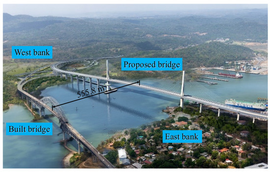
Figure 1.
Effect picture of the existing truss-arch bridge and the proposed cable-stayed bridge.
The upstream bridge, which was built in the 1960s, is a steel truss-arch bridge with fourteen spans. As shown in Figure 2, a typical steel–concrete composite girder has a main span of 343.8 m, a width of 14.05 m, and a height of 1.73 m. The heights of the deck and truss-arch vault to the mean navigable level are 61.3 m and 132 m, respectively. The preliminary design scheme of the proposed bridge is depicted in Figure 3. The bridge has nine spans with a main span of 510 m. The girder has a width of 51 m and a height of 5 m, and a train track system is installed in the center of the upper surface of the bridge deck. Two single-column pylons with a height of 212.6 m are used, and a restaurant with a flying disk shape is located outside the west pylon. The design wind speed is 43.5 m/s for the maximum single cantilever state and 54.6 m/s for the completed state of the bridge.
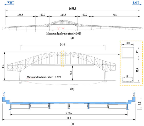
Figure 2.
Schematic description of the existing bridge (unit: m): (a) general layout; (b) layout of main span; (c) typical cross section.
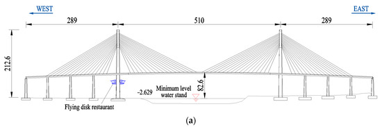
Figure 3.
Schematic description of the proposed bridge (unit: m): (a) general layout; (b) typical cross section.
2.2. Set-Up of Tests
The tests were performed in the XNJD-3 wind tunnel at Southwest Jiaotong University. The working section of the wind tunnel has a height, width, and length of 4.5 m, 22.5 m, and 36 m, respectively. The wind speed can be adjusted within 0.5~16.5 m/s, and the turbulence intensity in the empty wind tunnel is less than 1.0% when the wind speed is higher than 1.5 m/s. The wind field simulated by spires and roughness elements adhered to wind exposure category C specified in the AASHTO LRFD Bridge Design Specifications [31]. Instantaneous wind speeds were measured through a TFI Cobra probe, which has a frequency response of 0~2000 Hz; the measured wind speed range is from 2 m/s to 100 m/s, and the measuring accuracy is ±0.1 m/s.
The geometric scale of models was set as 1:100. A rigid model of the upstream bridge was manufactured from acrylonitrile butadiene styrene plastic material. To study the wind-induced responses of the downstream bridge, an aeroelastic model of the proposed cable-stayed bridge was designed following Froude similarity. The bridge deck was composed of steel core beams and acrylonitrile butadiene styrene plastic material, which were used to simulate the mechanical properties and aerodynamic shapes, respectively. The mass and mass moment of inertia were satisfied by added masses inside the model. The external covering of the deck model consisted of 43 segments. There was a 1.5 mm gap between each segment to avoid additional stiffness. Similarly, the stiffness and aerodynamic shape of the towers were simulated by the steel core beams and the external claddings manufactured by high-quality timber, respectively. Lead added masses were fixed inside the timber coat. The two full-bridge models in the wind tunnel are shown in Figure 4. The wind direction is orthogonal to the downstream bridge, and the wind attack angle was 0° in the tests. The displacement measuring was conducted by a laser sensor, whose measuring range was 200 mm, measurement precision was 40 μm, and maximal sample rate was 1000 Hz. The sampling frequency and period were 256 Hz and 64 s. The testing results of the dynamic characteristics of the aeroelastic model are listed in Table 1 and Table 2 (L, V, and T are the abbreviations for lateral, vertical, and torsional, respectively, and S and A are the abbreviations for symmetrical and antisymmetrical, respectively; the numbers represent the order of the mode shapes). Note that the mode of the first lateral symmetrical bending of the tower and bridge deck was coupled. The frequency simulation errors of the bridge deck model were all controlled within ±5%, meeting the testing requirements [32]. To ensure conservative design, the upper limit of wind speed for subsequent wind tunnel tests was set at 120% of the design wind speed. Specifically, test wind speeds were extended to 5.22 m/s for the maximum single cantilever state and 5.46 m/s for the completed state, corresponding to prototype wind speeds of 52.2 m/s and 54.6 m/s, respectively.
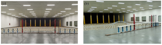
Figure 4.
Full-bridge aeroelastic models: (a) without upstream bridge; (b) with upstream bridge.

Table 1.
Tested parameters of the proposed bridge in the maximum single cantilever state.
Table 2.
Tested parameters of the proposed bridge in the completed state.
3. Effects of the Upstream Bridge on Downstream Wind Characteristics
To study the interference effect of the upstream bridge, the wind characteristics at the midspan of the proposed bridge with and without the existing upstream bridge were compared in detail, including the wind speed profiles, turbulent intensity profiles, integral scales, and wind power spectra.
3.1. Mean Wind Speed Profile
In the AASHTO [31], the wind speed profile is specified following the logarithm law, and the wind exposure category C can be written as
where H is the height above the ground, and UH is the wind speed at H.
Figure 5 illustrates the mean wind speed profiles at the midspan of the proposed bridge, where the testing results have been converted to the prototype bridge. The solid line was obtained by fitting the test data without the upstream bridge using Equation (1). The results align with the fitted profile, indicating that the mean wind speeds were accurately simulated in the wind tunnel. The mean wind speed profile is changed significantly by the influence of the upstream bridge. Owing to the wake of the upstream bridge, the wind speed within the height range of the main girder and truss arch of 40 m < H < 130 m decrease remarkably at the downstream bridge site. Simultaneously, according to the conservation of flow, the wind speed influenced by the upstream bridge is slightly higher than that without the upstream bridge when H ≤ 40 m and H ≥ 130 m. For the height of the proposed bridge deck, the mean wind speed is reduced by approximately 9.2%.
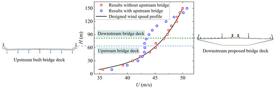
Figure 5.
Mean wind speed profiles at the midspan of the proposed bridge deck.
3.2. Turbulence Intensity
The turbulence intensity for the wind exposure category C can be written as
Figure 6 shows the total turbulence intensity profiles at the midspan of the proposed bridge deck, as well as the turbulence intensities for components u (longitudinal), v (lateral), and w (vertical). It can be seen that the turbulence intensities for component u are the largest, followed by those for component v and finally for component w. Under the interference of the upstream bridge, the turbulence intensities significantly increase, especially within the height range of 50~120 m with more structural members, which perturb the incoming flow more significantly. The turbulence intensities of components u and w increase remarkably when 60 m ≤ H ≤ 130 m under the interference of the upstream bridge, while the increase in turbulence intensities of component v is very limited. In Figure 6a, the solid line is the target values calculated using Equation (2). The measured turbulence intensities without the upstream bridge approximately align with the target values. For the height of the proposed bridge deck, the total turbulence intensity increases from 14.6% to 16.7%, with an increase rate of 14.4%.
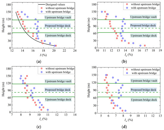
Figure 6.
Turbulence intensity profiles at the midspan of the proposed bridge deck: (a) total turbulence intensity; (b) u component; (c) v component; (d) w component.
3.3. Integral Scale
The integral scales at different heights with and without the interference of the upstream bridge are shown in Figure 7. According to the AASHTO [31], the recommended value of the integral length scale at the height of the proposed bridge deck is 183.10 m, while the testing results showed that the scale was approximately 87 m. Due to the limitations of existing wind tunnels, the simulated turbulence integral scale was remarkably lower than that in the actual atmospheric boundary layer, which may lead to the underestimation of the buffeting responses [33,34,35]. In fact, current research is still unable to quantify the impact. However, it is generally accepted in the industry that when the integral scale simulated in wind tunnels is significantly larger than the width of the bridge, the effect of this deviation of the simulation from the actual scale on the test results is negligible [36,37,38]. As shown in Figure 7, the integral length scales decrease remarkably with the influence of the upstream bridge, especially for component u. For example, at the height of the proposed bridge deck, Lu, Lv, and Lw decreases by 41.90%, 23.26%, and 29.11%, respectively. Apparently, the additional turbulence in the wake generated by the upstream bridge has a much smaller integral scale.
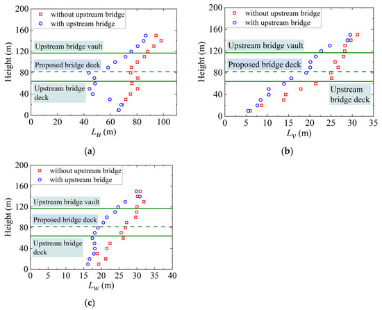
Figure 7.
Integral scales at the midspan of the proposed bridge deck: (a) u component; (b) v component; (c) w component.
3.4. Wind Speed Spectra
The von Kármán model [39] is widely used to describe fluctuating wind in wind tunnels and the atmospheric boundary layer [40,41]. The expressions of the components u, v, and w can be written as
where Su,v,w (f) denotes the wind speed spectra, f is the frequency, σu,v,w is the fluctuating root-mean-square (RMS) of wind speeds, and Lu,v,w is the turbulent integral scale.
Figure 8 shows the measured wind spectra at the height of the bridge deck with and without the upstream bridge for the three components. The fitted curves based on the von Kármán spectra are also presented. The figure shows that the wind spectra for the three components are all distributed in higher frequencies due to the changes in the turbulence integral scale, especially for component u.
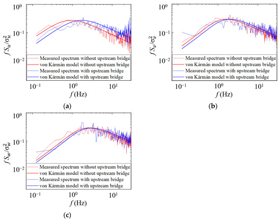
Figure 8.
Fluctuating wind speed spectra at the midspan of the proposed bridge deck: (a) u component; (b) v component; (c) w component.
4. Influence of the Upstream Bridge on Wind-Induced Vibration Responses
To investigate the influence of the upstream bridge on the wind-induced vibration of the downstream bridge, the mean and buffeting response of the cantilever end in the maximum single cantilever state and the midspan in the completed state were obtained with and without the upstream bridge. Moreover, the peak responses were calculated using the equivalent static method to evaluate the wind-induced response of the downstream bridge deck. The peak factor was given by Davenport [42] to account for the fluctuating load, and the peak response can be calculated using
where RP, RQ, and RR are the peak, mean, and buffeting responses, respectively, and gR is the peak factor.
4.1. Mean Displacement
The mean displacements of the cantilever end in the maximum single cantilever state and the midspan in the completed state are shown in Figure 9 and Figure 10, respectively. It can be seen that the vertical mean displacements are significantly lower than the lateral mean displacements under the same wind speed. With the increase in the wind speed, the vertical mean displacements increase slowly because of the small lift coefficient, and the lateral and torsional mean displacements increase in a roughly quadratic curve. Compared to those in the completed state, the lateral and torsional mean displacements of the downstream bridge deck are larger in the maximum single cantilever state due to the lack of overall structural stiffness. When the wind speed reached the maximum test speed of 52.2 m/s in the maximum single cantilever state, for the case without the upstream bridge, the maximum lateral and torsional mean displacements of the cantilever end in the maximum single cantilever state are 61.8% and 77.5% larger than those of the midspan in the completed state, and under the interference of the upstream bridge, the values are 63.8% and 81.8%, respectively. As shown in Figure 9 and Figure 10, the mean displacements of the downstream bridge deck in the three directions in both studied states all decrease with the interference of the upstream bridge. This echoes the abovementioned results in which the wind speeds decreased with the influence of the upstream bridge, leading to a decrease in the mean aerodynamic force acting on the downstream bridge. At the wind speed of 52.2 m/s, the lateral, vertical, and torsional mean displacements decrease by 10.2%, 15.9%, and 11.0%, respectively, in the maximum single cantilever state and by 9.4%, 13.9%, and 13.1%, respectively, in the completed state. It is worth noting that the structural form characteristics of the arch bridge (the significant variability of the structural strips along the span) make its influence on the downstream wind field significantly non-uniform, and the degree of influence of the upstream bridge on the mean displacement of the downstream bridge is not squared by that on the wind speed at the downstream bridge site, as the theory suggests.
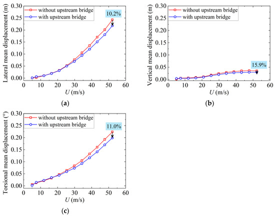
Figure 9.
Mean displacements at the cantilever end of the proposed bridge in the maximum single cantilever state: (a) lateral; (b) vertical; (c) torsional.
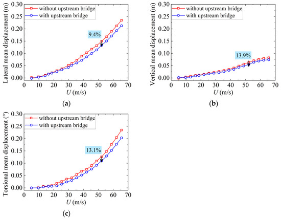
Figure 10.
Mean displacements at the midspan of the proposed bridge in the completed state: (a) lateral; (b) vertical; (c) torsional.
4.2. Buffeting Displacement
Figure 11 and Figure 12 show the RMSs of buffeting displacements of the cantilever end in the maximum single cantilever state and the midspan of the deck in the completed state under various wind speeds. The buffeting displacements of the downstream bridge deck change with the wind speeds in an approximate quadratic regardless of the upstream bridge. The variation curve of the lateral buffeting displacements with varying wind speeds is not smooth, indicating that the lateral buffeting response is more obviously random. In addition, the buffeting displacements in three directions all increase to a certain degree with the influence of the upstream bridge under the same mean wind speed. Actually, as mentioned above, the turbulence intensity at the height of the downstream bridge deck increases and the integral scale decreases in response to the interference from the upstream bridge. Theoretically, the changes in these two fluctuating wind parameters will result in an increase and decrease, respectively, in the buffeting response. Consequently, the influence of the turbulence intensity variations on the downstream bridge buffeting response is more significant compared to the integral scale in this case. In the case of U = 52.2 m/s, under the interference effect of the upstream bridge, the lateral, vertical, and torsional buffeting displacements of the downstream bridge’s cantilever end in the maximum single cantilever state increase by 24.6%, 11.3%, and 3.4%, respectively, and the growth values of the midspan in the completed state are 22.1%, 12.3%, and 14.8%, respectively. The lateral buffeting response is more sensitive to the interference of the upstream bridge.
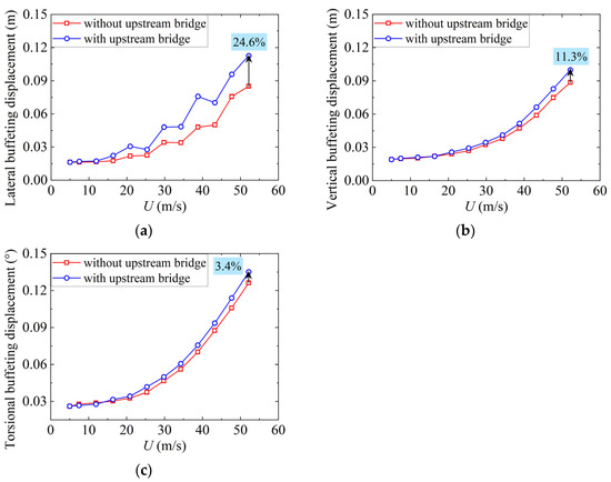
Figure 11.
Buffeting displacements at the cantilever end of the proposed bridge in the maximum single cantilever state: (a) lateral; (b) vertical; (c) torsional.
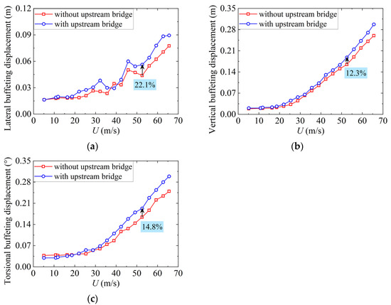
Figure 12.
Buffeting displacements at the midspan of the proposed bridge in the completed state: (a) lateral; (b) vertical; (c) torsional.
To achieve a better understanding of the buffeting, spectral analysis was conducted. The buffeting displacement spectra under the wind speed of 52.2 m/s are shown in Figure 13 and Figure 14.
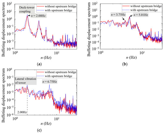
Figure 13.
Buffeting displacement spectra at the cantilever end of the proposed bridge in the maximum single cantilever state: (a) lateral; (b) vertical; (c) torsional.
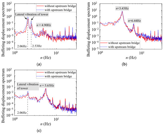
Figure 14.
Buffeting displacement spectra at the midspan of the proposed bridge in the completed state: (a) lateral; (b) vertical; (c) torsional.
For lateral buffeting displacements, as shown in Figure 13a, the lateral bending vibrations of the bridge deck and tower are obviously coupled in the maximum single cantilever state (n = 2.00 Hz), which is consistent with the mode parameters listed in Table 1 and Table 2. According to the buffeting displacement spectra at the midspan of the proposed bridge in the completed state, the lateral bending vibrations of the tower have a significant impact on the buffeting response of the bridge deck. This indicates that the lateral stiffness of the tower is lower than that of the deck, causing the lateral motion of the deck driven by the tower’s lateral bending vibration to dominate the lateral buffeting response. On the contrary, due to the relative magnitude of stiffness, even though the motion of the tower contributes varying degrees to the vertical and torsional responses, the modal contribution of the deck still dominates, as shown in Figure 13b,c and Figure 14b,c. It should be noted that for the vertical buffeting displacements, the second vibration mode is dominant in the maximum single cantilever state, while the first vibration mode is dominant in the completed state.
On the other hand, owing to the changes in frequency distribution of the wind spectra caused by the changes in the integral scales, the turbulent energy and the induced bridge buffeting displacement spectra shift overall to high frequencies with the influence of the upstream bridge. As shown in Figure 8, the migration in the longitudinal direction is most significant. In view of the large contributions of longitudinal fluctuating wind, the lateral and torsional displacements change more significantly under the interference of the upstream bridge, as shown in Figure 13 and Figure 14.
4.3. Peak Wind-Induced Response
Peak response can be adopted to evaluate the wind load for long-span bridge designs. In this study, the peak factor gR was set as 3.4 according to the AASHTO [31]. Based on the testing results, the peak displacements of the cantilever end in the maximum single cantilever state and the midspan in the completed state with varying wind speeds are shown in Figure 15 and Figure 16. The lateral peak displacement is significantly greater than the vertical displacement at a certain wind speed in the maximum single cantilever state, while the former is lower than the latter in the completed state. The peak displacements of the downstream bridge all increase under the interference of the upstream bridge. When the wind speed is 52.2 m/s, the lateral peak displacements of the cantilever end in the maximum cantilever state and the midspan in the completed state increase by 13.0% and 8.5% under the interference of the upstream bridge, respectively. In fact, the mean displacement of the downstream bridge deck decreases while the buffeting displacement increases with the interference. In other words, the variation in buffeting response is much more significant and dominates the peak response, indicating that the comfort of users caused by structural buffeting may need more attention under the interference of an upstream bridge. For the torsional direction, the peak displacements under the two states are relatively close, while the change rate in the completed state is significantly larger than that in the maximum single cantilever state under aerodynamic interference.
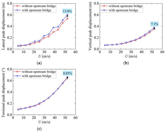
Figure 15.
Peak displacements at the cantilever end of the proposed bridge in the maximum single cantilever state: (a) lateral; (b) vertical; (c) torsional.
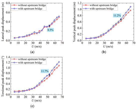
Figure 16.
Peak displacements at the midspan of the proposed bridge in the completed state: (a) lateral; (b) vertical; (c) torsional.
5. Conclusions
A detailed investigation of the influence of an upstream bridge on the aerodynamic interference and wind-induced responses of a long-span cable-stayed bridge was conducted in this study. The wind characteristics at the downstream bridge site, including the wind speed profile, turbulent intensity, integral scale, and wind power spectrum, were measured, and the mean, buffeting, and peak displacements of the downstream bridge were analyzed under the interference of the upstream arch bridge. The main conclusions can be drawn as follows:
- (1)
- The presence of the upstream bridge has a significant influence on the wind characteristics at the downstream bridge site. The mean wind speed within the height range of the main girder and truss arch decreased remarkably. The turbulence intensities significantly increased, especially for the components u and w within the height range of the main girder and truss arch. The integral length scales significantly decreased with the influence of the upstream bridge, especially for component u, resulting in redistribution of the wind speed spectra toward higher frequencies.
- (2)
- The mean displacements of the downstream bridge in the three directions all decreased with the influence of the upstream bridge in both the maximum single cantilever state and the completed state. In contrast, the peak displacements all increased, indicating that the term of the buffeting component is dominant in the analysis of the peak responses.
- (3)
- Under the interference of the upstream bridge, the influence of the turbulence intensity variations on the downstream bridge buffeting response was more significant compared to the integral scale, and the buffeting displacements in the three directions all increased. Among them, the lateral buffeting response was more sensitive to the aerodynamic interference. The buffeting displacement spectra migrated to high frequencies with the interference of the upstream bridge due to a similar change in the wind speed spectra. In addition, with the influence of the upstream bridge, the variation in buffeting response was much more significant and dominated the peak response, indicating that user comfort needs more attention for parallel bridges, even when no significant changes are generated in the static wind-induced responses.
In conclusion, the presence of an upstream bridge may significantly compromise the wind resistance performance of downstream bridges, necessitating careful evaluation in structural design. When necessary, systematic investigation should be conducted through approaches such as modifying structural aerodynamic configurations and increasing parallel bridge spacing to mitigate these aerodynamic interference effects.
Author Contributions
Conceptualization, Y.S. (Yanguo Sun) and T.Z.; methodology, Y.S. (Yi Su) and M.L.; validation, M.L. and J.D.; investigation, T.Z., J.S., Y.Q. and R.S.; resources, M.L. and J.S.; data curation, J.D., Y.S. (Yi Su) and Y.Q.; writing—original draft preparation, T.Z. and R.S.; writing—review and editing, Y.S. (Yanguo Sun); project administration, M.L. and J.S.; funding acquisition, Y.S. (Yanguo Sun) and Y.S. (Yi Su). All authors have read and agreed to the published version of the manuscript.
Funding
This research was funded by the National Natural Science Foundation of China [grant numbers 52178508 and 52208462] and the Natural Science Foundation Project of Chongqing [grant number CSTB2023NSCQ-MSX1054].
Institutional Review Board Statement
Not applicable.
Informed Consent Statement
Not applicable.
Data Availability Statement
Data will be made available on request.
Acknowledgments
The authors thank the reviewers for their great help on the article during its review process.
Conflicts of Interest
Author Tianyi Zhang was employed by the company Sichuan Road & Bridge Group Co., Ltd. Author Jiapeng Shi was employed by the company China Harbour Engineering Company Ltd. The remaining authors declare that the research was conducted in the absence of any commercial or financial relationships that could be construed as a potential conflict of interest.
References
- Li, H.; He, X. Lateral aerodynamic interference between an interior train and a flat box bridge-deck. Exp. Therm. Fluid Sci. 2020, 117, 110115. [Google Scholar] [CrossRef]
- Xia, J.; Li, K.; Ge, Y. Span-wise coherence of fluctuating forces on twin bridge decks and the turbulence effect. Adv. Struct. Eng. 2019, 22, 3207–3221. [Google Scholar] [CrossRef]
- Kimura, K.; Shima, K.; Sano, K.; Ukon, H. Effects of separation distance on wind-induced response of parallel box girders. J. Wind Eng. Ind. Aerod. 2008, 96, 954–962. [Google Scholar] [CrossRef]
- Laima, S.; Li, H. Effects of gap width on flow motions around twin-box girders and vortex-induced vibrations. J. Wind Eng. Ind. Aerod. 2015, 139, 37–49. [Google Scholar] [CrossRef]
- He, X.; Kang, X.; Yan, L.; Flay, R.G.J.; Ren, P.; Wu, T. Numerical investigation of flow structures and aerodynamic interference around stationary parallel box girders. J. Wind Eng. Ind. Aerod. 2021, 215, 104610. [Google Scholar] [CrossRef]
- Honda, A.; Shiraishi, N.; Matsumoto, M.; Fuse, Y.; Sumi, K.; Sasaki, N. Aerodynamic stability of Kansai International Airport access bridge. J. Wind Eng. Ind. Aerod. 1993, 49, 533–542. [Google Scholar] [CrossRef]
- Kim, S.J.; Kim, H.K.; Calmer, R.; Park, J.; Kim, G.S.; Lee, D.K. Operational field monitoring of interactive vortex-induced vibrations between two parallel cable-stayed bridges. J. Wind Eng. Ind. Aerod. 2013, 123, 143–154. [Google Scholar] [CrossRef]
- Argentini, T.; Rocchi, D.; Zasso, A. Aerodynamic interference and vortex-induced vibrations on parallel bridges: The Ewijk bridge during different stages of refurbishment. J. Wind Eng. Ind. Aerod. 2015, 147, 276–282. [Google Scholar] [CrossRef]
- Meng, X.; Zhu, L.; Guo, Z. Aerodynamic interference effects and mitigation measures on vortex-induced vibrations of two adjacent cable-stayed bridges. Front. Archit. Civ. Eng. China 2011, 5, 510–517. [Google Scholar] [CrossRef]
- Ishihara, T.; Li, T. Numerical study on suppression of vortex-induced vibration of circular cylinder by helical wires. J. Wind Eng. Ind. Aerod. 2020, 197, 104081. [Google Scholar] [CrossRef]
- Corriols, A.S.; Morgenthal, G. Vortex-induced vibrations on cross sections in tandem arrangement. Struct. Eng. Int. 2014, 24, 20–26. [Google Scholar] [CrossRef]
- Seo, J.W.; Kim, H.K.; Park, J.; Kim, K.T.; Kim, G.N. Interference effect on vortex-induced vibration in a parallel twin cable-stayed bridge. J. Wind Eng. Ind. Aerod. 2013, 116, 7–20. [Google Scholar] [CrossRef]
- Park, J.; Kim, S.J.; Kim, H.K. Effect of gap distance on vortex-induced vibration in two parallel cable-stayed bridges. J. Wind Eng. Ind. Aerod. 2017, 162, 35–44. [Google Scholar] [CrossRef]
- Park, J.; Kim, H.K. Effect of the relative differences in the natural frequencies of parallel cable-stayed bridges during interactive vortex-induced vibration. J. Wind Eng. Ind. Aerod. 2017, 171, 330–341. [Google Scholar] [CrossRef]
- He, H.; Li, W. Study on the effect and mechanism of aerodynamic measures for the vortex-induced vibration of separate pairs of box girders in cable-stayed bridges. Shock Vib. 2015, 1, 792957. [Google Scholar] [CrossRef]
- Sun, Y.; Liu, Q.; Shao, L.; Wang, Y.; Chang, X.; Liu, K. Experimental investigation of aerodynamic forces and vortex-induced vibrations of wavy cylinders at subcritical Reynolds numbers. Exp. Therm. Fluid Sci. 2023, 144, 110869. [Google Scholar] [CrossRef]
- Sarkar, P.P. New Identification Methods Applied to the Response of Flexible Bridges to Wind. Ph.D. Thesis, The Johns Hopkins University, Baltimore, MD, USA, 1993. [Google Scholar]
- Miyata, T. Significance of aero-elastic relationship in wind-resistant design of long-span bridges. J. Wind Eng. Ind. Aerod. 2002, 90, 1479–1492. [Google Scholar] [CrossRef]
- Fok, C.H.; Kwok, K.C.S.; Qin, X.R. Sectional pressure tests of a twin-deck bridge: Part 2: Effects of gap-width on a twin-deck configuration. In Proceedings of the 11th AWES Workshop, Darwin, Australia, 28–29 June 2004. [Google Scholar]
- Kwok, K.C.S.; Qin, X.R.; Fok, C.H.; Hitchcock, P.A. Wind-induced pressures around a sectional twin-deck bridge model: Effects of gap-width on the aerodynamic forces and vortex shedding mechanisms. J. Wind Eng. Ind. Aerod. 2012, 110, 50–61. [Google Scholar] [CrossRef]
- Yang, Y.; Wu, T.; Ge, Y.; Kareem, A. Aerodynamic stabilization mechanism of a twin box girder with various slot widths. J. Bridge Eng. 2015, 20, 04014067. [Google Scholar] [CrossRef]
- Boonyapinyo, V.; Junruang, J. Aerodynamic and aerostatic responses of two parallel cable-stayed bridges. In Proceedings of the 15th International Conference on Wind Engineering, Beijing, China, 1–6 September 2019. [Google Scholar]
- Montoya, M.C.; Nieto, F.; Hernández, S.; Fontán, A.; Jurado, J.A.; Kareem, A. Optimization of bridges with short gap streamlined twin-box decks considering structural, flutter and buffeting performance. J. Wind Eng. Ind. Aerod. 2021, 208, 104316. [Google Scholar] [CrossRef]
- Xin, J.; Zhou, C.; Jiang, Y.; Tang, Q.; Yang, X.; Zhou, J. A signal recovery method for bridge monitoring system using TVFEMD and encoder-decoder aided LSTM. Measurement 2023, 214, 112797. [Google Scholar] [CrossRef]
- Li, T.; Yang, Q.; Zhang, C.; Ren, C.; Liu, M.; Zhou, T. A novel non-Gaussian analytical wake model of yawed wind turbine. J. Wind Eng. Ind. Aerod. 2025, 259, 106040. [Google Scholar] [CrossRef]
- Shi, F.; Wang, L.; Dong, F.; Zhao, M. Probabilistic analysis on aerostatic displacement-dependent wind loads on a stream-lined box girder. KSCE J. Civ. Eng. 2023, 27, 299–312. [Google Scholar] [CrossRef]
- Tao, T.; Wang, H. Efficient buffeting analysis of long-span bridges under non-stationary winds: A 2D interpolation enhanced approach. J. Sound Vib. 2023, 559, 117754. [Google Scholar] [CrossRef]
- Wen, Q.; Hua, X.; Lei, X.; Chen, Z.; Niu, H. Experimental study of wake-induced instability of coupled parallel hanger ropes for suspension bridges. Eng. Struct. 2018, 167, 175–187. [Google Scholar] [CrossRef]
- Su, Y.; Di, J.; Zuo, T.; Li, S.; Qin, F. Buffeting response evaluation of slender linear structures considering the influence of the aspect ratio on the scale effect. J. Sound Vib. 2022, 530, 116969. [Google Scholar] [CrossRef]
- Tao, T.; Wang, H. Simulation of multivariate ergodic stochastic processes using adaptive spectral sampling and non-uniform fast Fourier transform. Probabilist. Eng. Mech. 2024, 77, 103669. [Google Scholar] [CrossRef]
- American Association of State Highway and Transportation Officials (AASHTO) LRFD. Bridge Design Specifications, 8th ed.; AASHTO: Washington, DC, USA, 2017. [Google Scholar]
- Ministry of Transport of the People’s Republic of China. Wind-Resistant Design Specification for Highway Bridges: JTG/T 3360-01-2018; China Communications Press: Beijing, China, 2018. (In Chinese) [Google Scholar]
- Acebedo, R.; Kim, S.W.; Hwang, Y.C. Effect of turbulence length scale on vortex induced vibration of twin deck bridge section. In Proceedings of the 2016 World Congress on Advances in Civil, Environmental, and Materials Research (ACEM 16), Jeju Island, Republic of Korea, 28 August–1 September 2016. [Google Scholar]
- Su, Y.; Li, M.; Di, J.; Sun, R.; Li, M.; Qin, F.; Jiang, Y.; Wang, J. Scale effects on buffeting response of long-span bridges. Eng. Struct. 2025, 341, 120862. [Google Scholar] [CrossRef]
- Su, Y.; Li, M.; Yang, Y.; Di, J.; Yang, X.; Zhao, N. Prediction method for bridge buffeting responses based on the integrated transfer function identified via segmental model vibration test. J. Wind Eng. Ind. Aerod. 2023, 242, 105578. [Google Scholar] [CrossRef]
- Holmes, J.D. Prediction of the response of a cable stayed bridge to turbulence. In Proceedings of the 4th International Conference of Wind Effects on Building and Structures, London, UK, 20–22 August 1975. [Google Scholar]
- Han, X.; Li, Q. Effects of turbulence intensity and integral length scale on wind-induced vibrations of a three-dimensional aeroelastic square cylinder. Eng. Struct. 2025, 322, 119095. [Google Scholar] [CrossRef]
- Laima, S.; Feng, H.; Li, H.; Jin, Y.; Han, F.; Xu, W. A Buffeting-Net for buffeting response prediction of full-scale bridges. Eng. Strucut. 2023, 275, 115289. [Google Scholar] [CrossRef]
- von Kármán, T. Progress in the statistical theory of turbulence. Proc. Natl. Acad. Sci. USA 1948, 34, 530–539. [Google Scholar] [CrossRef] [PubMed]
- Li, T.; Yang, Q.; Ishihara, T. Unsteady aerodynamic characteristics of long-span roofs under forced excitation. J. Wind Eng. Ind. Aerod. 2018, 181, 46–60. [Google Scholar] [CrossRef]
- Su, Y.; Li, M.; Hui, Y.; Li, S.; Jiang, Y.; Jiang, W. Fluctuating wind load encountered by linearly moving vehicles: Investigation on fluctuating wind spectral characteristics. Eng. Struct. 2024, 319, 118879. [Google Scholar] [CrossRef]
- Davenport, A.G. The response of slender line-like structures to a gusty wind. ICE Proc. 1962, 23, 389–408. [Google Scholar] [CrossRef]


Disclaimer/Publisher’s Note: The statements, opinions and data contained in all publications are solely those of the individual author(s) and contributor(s) and not of MDPI and/or the editor(s). MDPI and/or the editor(s) disclaim responsibility for any injury to people or property resulting from any ideas, methods, instructions or products referred to in the content. |
© 2025 by the authors. Licensee MDPI, Basel, Switzerland. This article is an open access article distributed under the terms and conditions of the Creative Commons Attribution (CC BY) license (https://creativecommons.org/licenses/by/4.0/).