Article

Mathematical Modelling of Throughput in Peer-Assisted Symbiotic 6G with SIC and Relays

by
Muhammed Yusuf Onay
Department of Electrical-Electronics Engineering, Hitit University, TR-19030 Çorum, Turkey
Appl. Sci. 2025, 15(17), 9504; https://doi.org/10.3390/app15179504
Submission received: 29 July 2025 / Revised: 27 August 2025 / Accepted: 28 August 2025 / Published: 29 August 2025

Abstract

Sixth-generation (6G) communication systems, with ultra-wide bands, energy-autonomous end nodes, and dense connectivity, challenge existing network designs. Optimizing time resources with energy harvesting, backscatter communication, and relays is essential to maximize the total bit rate in multi-user symbiotic radio networks (SRNs) with blocked direct paths. The literature lacks a unified optimization treatment that explicitly accounts for imperfect successive interference cancellation (SIC). This study addresses this gap by proposing the first optimization framework to maximize total bit rate for energy-harvesting TDMA/PD–NOMA-based multi-cluster and relay-assisted peer-assisted SR networks. The two-phase architecture defines a tractable constrained optimization problem that jointly adjusts cluster-specific time slots ( τ and λ ). Incorporating QoS, signal power, and reflection coefficient constraints, it provides a compact formulation and numerical solutions for both perfect and imperfect SIC. Detailed simulations performed under typical 6G power levels, bandwidths, and energy-harvesting efficiencies demonstrate graphically that imperfect SIC significantly limits total throughput due to residual interference, while perfect SIC completely eliminates this ceiling under the same conditions, providing a significant capacity advantage. Furthermore, the gap between the two scenarios rapidly closes with increasing relay time margin. The findings demonstrate that network capacity is primarily determined by the triad of base station output power, channel noise, and SIC accuracy, and that the proposed framework achieves strong performance across the explored parameter space.

1. Introduction

Sixth-generation (6G) communication networks aim to surpass previous generations with ambitious goals such as high data transfer speeds and the simultaneous connection of billions of objects [1,2]. However, realizing this vision requires a corresponding reduction in energy consumption per bit. Especially in large-scale machine-like communication scenarios, constraints such as transmitter power budgets and limited battery life are becoming logistically unsustainable, driving network design toward new multiple access and resource allocation approaches focused on energy efficiency [3,4]. In this context, wireless energy harvesting from existing radio frequency (RF) signals in the environment stands out as a critical component of 6G’s “green communication” goals [5,6]. Modern rectenna designs and multi-source RF harvesting techniques enable active communication by providing continuous power to nodes in the microwatt range.
In this context, the symbiotic radio architecture offers an innovative approach that enables the simultaneous use of spectrum and energy resources by sharing active user signals with passive backscattering internet of things (IoT) devices [7,8]. Backscattering nodes offer low-cost and long-lasting solutions thanks to their ability to harvest energy from the environment while modulating the backhaul signal without the need for external RF generators. With these features, the SR architecture is considered a strong candidate for 6G’s “green communication” goals when integrated with TDMA/power domain–NOMA multiple-access mechanisms.
However, coexistent transmission in SR networks limits the total data transmission capacity due to residual interference, especially under imperfect SIC conditions. Most existing studies in the literature focus on power-sharing optimizations or conduct their analyses under the ideal SIC assumption [9]. However, globally organizing resources in the time domain (e.g., phase windows, cluster-specific slots) remains an unsolved research problem when considering variable energy harvesting efficiencies, reflection coefficients, and different power levels and multi-user models. Based on a network model with obstacles and relays in a multi-user system, a holistic analytical framework that takes into account imperfect SIC effects and optimizes the time-domain resource allocation on a global scale is missing in the literature. Such a framework is considered to be a critical requirement in the design of high-capacity and energy-efficient symbiotic radio networks for 6G [10].
In this study, a hybrid peer-assisted sum-throughput maximization approach is proposed for SRNs, considering the presence of obstacles and relays, and analyzing both perfect and imperfect SIC scenarios. It is assumed that no direct link exists between the backscatter device (BD) and the receiver due to the presence of obstacles. Therefore, the relay is responsible for forwarding the data from BD to the receiver. Since BD assists the BS via relay transmission, the BS can achieve its target throughput in a shorter time, thereby allowing a longer transmission duration for BD to send its own data to the receiver. Furthermore, this model offers a hybrid framework that combines TDMA and PD-NOMA in a cascaded peer-assisted architecture, addressing energy causality and interference management. The TDMA phase provides a secure window for energy harvesting and backscatter communication thanks to interference-free/overlap-free timing; in the first phase, TDMA limits interference, especially at low signal strengths. Subsequently, in the second phase, PD-NOMA enables power-domain multiplexing and synchronous transmission with SIC, improving spectral efficiency and total bit rate; the speed of TDMA alone is lower than NOMA [5]. Thus, the hybrid design provides better bitrate performance by balancing the low concurrency/bitrate limitation of TDMA and the susceptibility of NOMA to energy causality and SIC residual interference.

1.1. Related Works

In recent years, a large body of literature has emerged, ranging from minimum data rate optimization in symbiotic radio, backscatter, and NOMA/TDMA-based networks to harvest then transmit (HTT)-relayed backscatter architectures and energy-efficient multilayer ambient backscatter designs. These studies offer significant advances in various aspects, such as capacity analysis, beamforming, adaptive relay selection, distributed multiple-input and multiple-output (MIMO), joint power–time allocation, and energy efficiency optimization under imperfect SIC. However, a comprehensive framework that fully analyzes closed-form joint optimization of time division in multi-user scenarios in the presence of obstacles and relays, taking into account the residual interference of imperfect SIC, and encompasses all these effects along with the energy harvesting dynamics, is still lacking. The following subsection highlights these gaps and establishes the unique position of this work in the literature.
In [11], a peer-assisted NOMA-TDMA-based hybrid transmission method is proposed that maximizes the minimum data rate to improve fairness among backscattering devices by considering energy causality and imperfect SIC cases; it is shown that the method provides improvements in terms of system data rate and fairness compared to traditional NOMA and TDMA. In [12], a relay-assisted backscatter system based on the HTT protocol is designed for situations where direct connectivity is not available; the power-splitting factor and time slots are jointly optimized to increase capacity. It is shown that the proposed low-complexity solution provides near-optimal performance and significant capacity gains compared to traditional methods. In [13], a backscatter-assisted multi-layer green system architecture for industrial IoT is proposed to improve energy efficiency and a collective deep reinforcement learning-based algorithm is developed for resource management. The method is shown to significantly reduce the total energy consumption. In another study, channel capacity analysis and beam optimization are performed in MIMO-based ambient backscatter (AmBC) systems; it is shown that the upper limit of capacity can be reached in low signal-to-noise ratio (SNR) conditions and linear power gain can be achieved with the number of antennas [14]. In [15], a method based on optimal time allocation including adaptive backscatter coefficient and relay selection is proposed for a relay-assisted backscatter network that harvests only RF energy; it is shown that the method increases the total system efficiency and provides up to 33% gain over classical systems. In [16], a novel distributed MIMO-enabled architecture is proposed for battery-free backscatter-based IoT networks, with three contributions: energy beam-bundling, distributed receiver combining, and auxiliary transmission. In particular, Rx-enabled distributed energy beam-bundling is experimentally shown to provide more than 130% power gain compared to conventional blind bundling. In another study, an optimal beamforming design is proposed that minimizes the source power by satisfying the energy constraints of the source and tags in a multi-antenna source and receiver multi-tag BackCom system; it is shown that the method converges quickly and provides significant power savings compared to existing methods [17]. It is also reported that the proposed algorithm provides savings of up to 20 dBm compared to classical maximum-eigenvalue-based methods. In [18], two resource allocation methods based on NOMA and OMA are proposed for hybrid relay-assisted wireless energy MC-IoT systems, optimizing the total data transmission. Simulations showed that the proposed methods provide higher data transmission compared to traditional approaches. In [19], a two-stage framework incorporating active/passive beamforming and resource optimization is proposed for multi-antenna backscatter-assisted collaborative NOMA IoT networks, maximizing energy efficiency by supporting multiple antennas at both transmitter and backscatter. It is shown that the proposed algorithm converges quickly with low complexity and provides significant energy efficiency gains compared to classical methods. In [20], a traditional two-user downlink NOMA system is expanded by adding an energy-constrained device that communicates via backscatter in the uplink. The device’s data transmission rate is maximized by optimizing its power and backscatter coefficients. Furthermore, a closed-form solution is derived, demonstrating that the system can integrate new IoT devices into existing networks without wasting bandwidth. In [21], a scenario is considered in multi-cell NOMA-based 6G IoT networks, where backscatter sensors transmit data by reflecting superposed signals; the source power, power sharing, and reflection coefficients are jointly optimized to maximize energy efficiency under imperfect SIC. Simulations show that the proposed backscatter-enabled NOMA network provides higher energy efficiency than the classical NOMA. In [22], a new relay selection algorithm is proposed for buffer-assisted cooperative NOMA networks with energy-harvesting relays, taking into account the data and energy buffer states; it is shown that the method reduces the probability of outages and increases the efficiency of the network, and increasing the energy buffer size significantly improves the performance. In another study, semi-closed form solutions that maximize the weighted total data rate for NOMA and TDMA in energy harvesting IoT networks are developed; it is shown that NOMA or TDMA may be more advantageous depending on the circuit power consumption [23]. In [24], a full-duplex relay-assisted and energy-harvesting NOMA-based hybrid cognitive radio network is proposed; outage probability and efficiency analysis are performed by considering self-interference and imperfect SIC effects in underlay/overlay modes, and it is shown that the method provides higher spectrum and energy efficiency compared to classical systems. In [25], the performance of 6G half-duplex relay-assisted uplink NOMA networks under co-channel interference (CCI) and imperfect SIC caused by nearby NOMA transmissions is analyzed, and it is shown that by optimizing the transmission power, power sharing coefficient and relay location, the CCI effect is reduced and the network performance is significantly improved. In [26], a backscatter-NOMA system is proposed, where cellular and IoT networks work together, while data is transmitted to two users via NOMA, a backscattered device provides additional data transfer using base station signals. Theoretical expressions are derived, analyzing the outage probability and ergodic ratios. The results showed that the system offers better performance compared to classical OMA at low SNR. In [27], a hybrid backscatter system that switches active/passive modes according to the energy harvested and uses opportunistic SIC is proposed. It is shown that the energy efficiency is increased by the adaptive reflection coefficient, resulting in lower outage probability compared to classical methods. In [28], the outage probability and ergodic capacity are analyzed for ambient backscatter systems in three different scenarios, and it is found that outage at high SNR is affected by the decoding constraint at the source terminal. In [29], a model is presented in which the backscatter device transmits information to two users in a NOMA-based system, and the relationship between the reflection coefficient and optimal power allocation is investigated. In [30], the secrecy rate in a single-ED symbiotic system under energy constraints is analyzed using SIC techniques. In [31], a new model with active/backscatter transmission and jamming support is proposed to increase secrecy in symbiotic networks with relays and barriers; it is shown that it provides higher secrecy compared to classical systems. In [32], the security is improved by increasing the secrecy rate in a jammer-supported symbiotic network with optimized time and power parameters under sensing errors. In another study [33], the authors proposed a symbiotic network with multiple users and used a time allocation method to improve the energy efficiency in the network. In [34], an energy/spectrum efficient SR architecture based on cognitive backscattering that shares spectrum and energy is proposed. In [35], spectral efficiency is increased by reducing multi-user interference in cell-free SR systems using various methods. In [36], it is shown that the system developed by combining backscattering and NOMA provides better performance than OMA in terms of outage probability and energy/data efficiency. In [37], an SR model that minimizes the transmission power of the relay is designed. In [38], an SR model based on SDMA and TDMA that maximizes the transmission rate of BDs is developed. In [39], an SIC-based SRN model with optimized power and reflection coefficients is proposed to increase the secrecy rate. In [40], a cooperation method is developed between IoT devices and BSs by taking into account the financial situation. In [41], SA and SDA methods are proposed for large-scale IoT connections. In [42], the effect of circuit sensitivity constraint on channel capacity in SR systems is analyzed. In [43], the paper builds a 3D GBSM for RSMA–IRS-assisted ISAC and uses PPO-based DRL to jointly optimize BS/IRS beamforming and rate-splitting for energy-efficiency under practical fading and QoS constraints, showing gains over Random/Greedy/SDMA baselines. In [44], the paper tackles STAR-RIS–assisted train-to-ground in SAGIN, jointly optimizing STAR-RIS phases (SDR+Gaussian randomization), UE–link association via a coalition game, and QoS-aware flow scheduling to maximize completed flows—outperforming SRAB/SRAA/RC/MFS and achieving near-exhaustive (ES) performance. Another study proposes a double-IRS auxiliary communications model for urban blockage with explicit IRS activation conditions and a virtual-Rician channel; it proves power gain scales with the fourth power of total geometric area, yet double reflection can underperform single reflection at practical IRS sizes [45].

1.2. Motivations and Contributions

Peer-assisted SRNs promise ultra-low-power mass connectivity in 6G; however, obstacles, the necessity of relays, and the residual interference of imperfect SIC limit this goal. The existing studies generally assume ideal SIC and do not jointly address time–energy allocation in TDMA/PD-NOMA-based multi-cluster networks. This critical gap highlights the need for a holistic time optimization framework that covers both perfect and imperfect SIC conditions in hybrid SRNs with obstacles and relays. This study examines a scenario in peer-assisted symbiotic networks enhanced by the backscatter technique, where direct communication links are unavailable due to obstacles, and information transmission is facilitated through relays in multi-user and multi-cell systems as in [12,24,25,31]. Relative to the closest works, ref. [11] studies a relay-free clustered TDMA/PD-NOMA setup with an iterative fairness objective, ref. [12] focuses on a single-link harvest-then-transmit relay without a symbiotic structure, and ref. [24] analyzes CR-NOMA with full-duplex relays and underlay/overlay mode switching, without symbiotic/backscatter radios or peer-assisted operation; in contrast, we model obstacle-induced mandatory relaying in multi-cluster SRNs and develop a capacity-centric, closed-form time-optimization framework under both perfect and imperfect SIC. This delivers actionable, scalable design rules for 6G-grade, energy-harvesting SRNs that existing analyses do not provide. In this model, which integrates TDMA and NOMA techniques, unlike the studies [31,32,41], the bit transmission rates of the data relayed to the receiver are analyzed under both perfect SIC and imperfect SIC conditions, and their theoretical upper bounds are determined. Additionally, the performance comparison between these two scenarios is presented graphically, and the variation in system performance with respect to different system parameters is thoroughly analyzed. In this respect, the proposed heterogeneous network model represents the first comprehensive approach in the literature specific to this topic.
This work presents a novel SRN model that is structurally and functionally different from traditional relay-based systems in [12,25,31]. Both the presence of physical obstacles [12] and the support of relay devices [25] are taken into account in the network structure, and in this respect, it is distinguished from classical SRN structures. In addition, a more flexible and high-capacity communication environment is provided by using TDMA and NOMA multiple access techniques in an integrated manner in the system as in [5]. Perfect and imperfect SIC cases are analyzed in detail, and capacity-based total system efficiency maximization problems for both cases are mathematically formulated. Owing to these aspects, the proposed model offers an innovative and optimized solution approach for the performance constraints encountered in multi-user and multi-cell SRN environments, clearly distinguished it from traditional relay systems and previous SRN models [21,30,33,35] in the literature.
To the best of our knowledge, there is no comprehensive study in the literature yet that addresses the joint optimization of time allocation parameters to maximize the system bit transmission rate under both perfect and imperfect SIC techniques in energy-harvesting based multi-user relay-assisted symbiotic radio networks. To fill this gap, a novel optimization framework is proposed to enhance the performance of power domain–NOMA-based symbiotic communication by considering the practical effects of imperfect SIC and the obstacles present in the environment.
The main contributions of this article are summarized as follows:
  • Joint time-domain framework: this is the first unified time-domain allocation framework that jointly allocates the TDMA backscatter window τ and the PD–NOMA duration λ under time normalization, energy-causality, and QoS, while consistently treating both perfect and imperfect SIC in multi-cluster SRNs with mandatory relaying.
  • Imperfect SIC (practical suitability): a parametric residual-interference factor z i is embedded into the SINR and QoS expressions of both phases, quantifying the performance degradation under imperfect cancellation and the gain under perfect SIC, thereby enhancing the practical suitability and realism of the model.
  • Scenario novelty and positioning: obstacle-induced mandatory relaying in multi-cluster SRNs with peer-assisted operation; unlike [11,12,24], our model jointly allocates time across both phases and explicitly accounts for SIC imperfections.
  • Capacity determinants: it is shown that network capacity is determined by the triad of base station power, channel noise, and SIC accuracy; the proposed scheme performs near the global optimum in this domain.
  • Actionable design rules: increasing fixed time fractional for relay is shown to rapidly close the perfect–imperfect SIC performance gap, providing clear design guidelines for 6G applications.

1.3. Paper Organization

The remainder of this paper is organized as follows. Section 2 presents the system model and describes the downlink—backscatter—relay signal flow. Section 3 formulates the mathematical framework and states tractable constrained optimization problems for both perfect and imperfect SIC scenarios. Section 4 provides a comprehensive numerical analysis to evaluate the proposed scheme under practical 6G conditions. Finally, Section 5 concludes the paper by summarizing the key findings.

2. System Model

In this study, a multi-user, energy-harvesting-based SRN is considered, consisting of a single-base station (BS), M backscatter end-devices BD n , n = 1 , 2 , , M , and a common receiver equipped with an assigned relay r n for each BD, as depicted in Figure 1. Since physical obstacles in the environment prevent direct connections between BD and receiver, the signal is carried over the BD n r n receiver path, while BS transmits its own data and provides an energy source to BDs. A list of the symbols used in this paper is provided in Table 1.
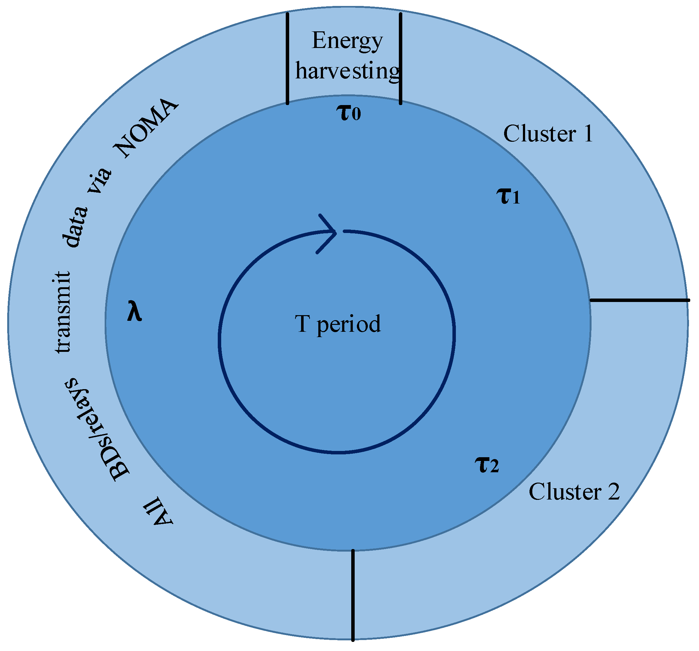
Figure 2 shows the proposed periodic structure for two-cluster peer-assisted NOMA communication. In this structure, there are three different subperiod slots, namely τ 0 , τ 1 and τ 2 during the time period T 1 . During the time interval T 1 , active communication takes place in a symbiotic relationship between the BS, BD 1 , BD 2 , r 1 and r 2 . The  τ 0 period represents the phase in which all users harvest energy from the BS, while the τ 1 and τ 2 periods represent the communication periods reserved for the first and second cluster, respectively. On the other hand, during the time interval T 2 , which covers the period λ , the BS switches to passive mode, since it is assumed that the amount of data to be transmitted by the BS to the receiver has already been satisfied. The cycle is normalized such that T 1 + T 2 = 1 s.
Figure 3 shows a general peer-assisted NOMA communication structure with clusters M. During the time period T 1 , a symbiotic communication takes place between the BS, BD n and r n . Each τ n denotes the communication period of cluster n. The structure is organized as a periodic cycle, which includes energy harvesting and data transmission stages as in the previous figure.
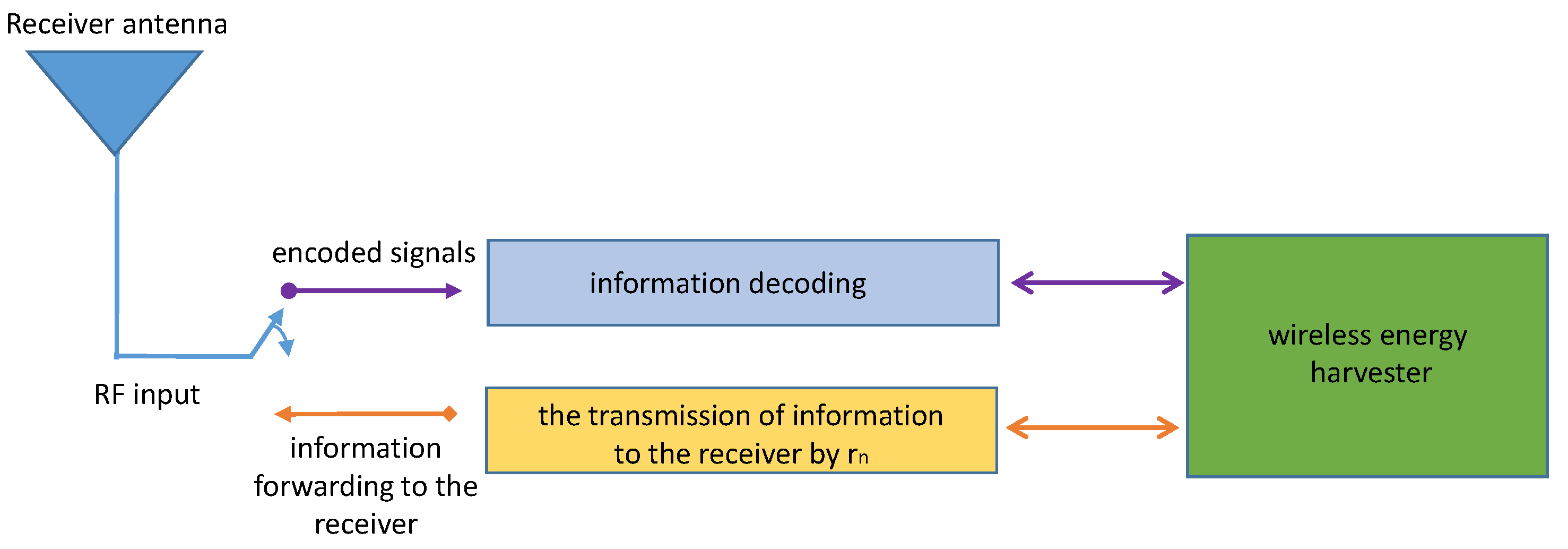
Each BD consists of power splitter-matching circuit, RF energy-harvesting module and capacitor-based storage unit, as shown in Figure 4. The incoming BS carrier is modulated and scattered back at α n rate, the remaining power at ( 1 α n ) rate is directed to energy harvesting. Figure 5 presents the block diagram of the r n relay, which performs the functions of wireless energy harvesting, signal decoding, and transmission of the decoded information to the receiver. r n is responsible for transmitting the BD’s information to the receiver.

Downlink, Backscatter, and Relay Signal Models

The signal transmitted from BS to BD n is as follows:
y n ( t ) = P H h n x ( t ) + n ( t )
where P H denotes the transmission power of the BS, x ( t ) is a known signal with unit energy, i.e.,  E [ x ( t ) 2 ] = 1 , and h n represents the channel gain between the BS and the BD n . PD-NOMA allows multiple cellular devices to communicate simultaneously over the same spectrum/time resources, significantly increasing the number of devices served. By carefully adjusting the transmission power, PD-NOMA also ensures fair resource allocation among different users sharing the same resources. In addition, n ( t ) denotes the additive white Gaussian noise (AWGN) at BD n , which is assumed to be identical across all terminals. The index n belongs to the set n = { 1 , 2 , , M } , where M denotes the total number of users. The received signal power at BD n from the BS is given by P H n = P H | h n | 2 .
BD n acts as a relay of BS and transmits the information of BS to the receiver by backscatter communication. Thus, the number of bits that BS needs to send to the receiver is reached faster.
Since there is no direct path from BD n to the receiver, information is transmitted to the receiver using r n . This means that r n acts as a relay for BD n . It is assumed that r n only decodes the data of BD n and harvests energy from the BS.
The backscattered signal from BD n is expressed as follows:
y b n ( t ) = P H α n h n x ( t ) z n ( t ) + z n ( t ) n ( t )
In this expression, z n ( t ) denotes the own signal of BD n . The parameter α n [ 0 , 1 ] is the power reflection coefficient of BD n , indicating that an α n portion of the received signal is backscattered for communication, while the remaining portion ( 1 α n ) is directed to the energy-harvesting circuit. The signal reaching r n can be written as follows:
y r n ( t ) = g n y b n ( t ) + g b s r n P H x ( t ) + n ( t )
In this equation, g n denotes the channel gain between BD n and r n , while g bs r n represents the channel gain between the BS and r n . Equation (4) is obtained by replacing the expression in Equation (2) into Equation (3).
y r n ( t ) = g n P H α n h n x ( t ) z n ( t ) The signal requested to be received by r n + g n z n ( t ) n ( t ) The noise resulting from backscatter + g bs r n P H x ( t ) BS induced interference + n ( t ) Additive noise
When the system is evaluated during T 2 , the BS is assumed to be silent. In this case, the signal transmitted from BDn to r n is realized by active data transmission technique. r n transmits the information transmitted to it to the receiver. Under the assumption that the relay accurately knows the information of the base station (BS), it has been shown in the literature that BS-induced interference can be eliminated at the receiving end y r n ( t ) using the SIC technique.

3. Mathematical Modeling

In this section, the mathematical formulation of the proposed system is developed; the relevant throughput and energy protocol expressions for the backscatter and active transmission phases are derived, and the analysis is carried out for perfect SIC scenarios in Section 3.1 and imperfect SIC scenarios in Section 3.2.

3.1. Perfect SIC Case

It is assumed that the perfect SIC technique is applied in the analysis of the received signals at the receiver side. Since the signal power of the BS is much higher than the backscattered signals, the interference originating from the BS can be effectively eliminated with the help of SIC. The SNR value at r n during T 1 is written as follows:
γ r n T 1 = P H h n 2 g n 2 α n ( g n 2 + 1 ) σ 2
where σ 2 denotes the noise power. Given that | g n | 2 1 , the equation can be approximated as follows:
γ r n T 1 = P H h n 2 g n 2 α n σ 2

3.1.1. Base Station-Plus-Peer-Assisted-Based Energy Harvesting Method for the Perfect SIC Case

Consistent with most previous studies [11,12,32], we adopt a linear energy-harvesting model to retain analytical tractability. This is justified because practical nonlinear rectifier characteristics can be well approximated by piecewise-linear segments—making linear-model results locally valid for each segment—and, in the low-input power regime typical of our setting, the nonlinear EH response is approximately linear. The energy harvested by BD 1 is written as follows:
E 1 = τ 0 P H | h 1 | 2 Previous energy harvesting τ 0 + τ 1 P H ( 1 α 1 ) | h 1 | 2 Current energy harvesting τ 1 + n = 2 M τ n P H α n | h n V n , 1 | 2 Peer assistance energy harvesting + n = 2 M τ n P H | h 1 | 2 Direct BS signal energy during others slots
Here, V n , 1 represents the channel gain between BD 1 and BD n . In this expression, the first term represents the energy harvested by BD1 from the BS during the τ 0 energy-harvesting phase. The second term describes the energy collected directly from the BS during τ 1 according to the power reflection coefficient ratio, excluding the part used for backscattering. The third term corresponds to the energy received from the backscattered signals of other BDs ( n = 2 , , M ) through their respective reflection coefficients. This mechanism is referred to as peer-assisted energy harvesting, where each BD contributes indirectly to the energy-harvesting of others by reflecting the BS’s signal during its own active slot. Lastly, the fourth term reflects the direct energy contribution from the BS during the active transmission slots of other BDs. The energy harvested by BD 2 is written as follows:
E 2 = τ 2 P H ( 1 α 2 ) h 2 2 + n = 0 , n 2 M τ n P H h 2 2 + n = 1 , n 2 M τ n P H h n V n , 2 2 α n
The energy harvested by BD n is generalized for M clusters as follows:
E n = j = 0 , j n M τ j P H h n 2 + τ n P H ( 1 α n ) h n 2 + j = 1 , j n M τ j P H α j h j V j , n 2
Here, V j , n denotes the channel gain between BD j and BD n . In this equation, the first term indicates the amount of energy harvested by BD n from the BS during the T 1 phase, excluding the time interval allocated for its own backscattering. The second term accounts for the energy acquired by BD n throughout its designated backscatter period. The third term reflects the energy collected from the signals reflected by other users during their respective backscatter durations.
The energy harvested by r 1 is written as follows:
E r 1 T 1 = η P H g b s r 1 2 τ 0 + η P H g b s r 1 2 τ 1
where η ( 0 , 1 ] represents the energy-harvesting efficiency coefficient. The period τ 1 is divided into two components according to the fixed time-fractional γ ( 0 , 1 ] .
τ 1 = γ τ 1 + ( 1 γ ) τ 1
Here, γ represents the fraction of time during which the relay operates as a receiver.
E c r 1 = P c r γ τ 1
where P c r is the circuit power consumed while the relay works as the receiver.
E c t 1 = P c t ( 1 γ ) τ 1
where P c t is denoted as the circuit power consumed while the relay works as a transmitter. Nowadays, the circuit power consumption of IoT nodes is quite low. For example, the MSP430 microcontroller, which is widely used in sensor nodes, operates with only a few hundred microwatts of power. In addition, with the advancement of semiconductor and manufacturing technologies, the circuit power consumption is further reduced. Therefore, the circuit power is quite low compared to the data transmission power. The power transmitted by r 1 during period T 1 is as follows:
P r 1 T 1 = E r 1 T 1 E c r 1 E c t 1 ( 1 γ ) τ 1
During the period T 1 , the r 1 used by BD 1 has used all its energy to serve the BS. The energy harvested after this period is aimed at serving BD 1 during the period T 2 . To find the power transmitted by r 1 during period T 2 , first the energy harvested by r 1 for period T 2 is written.
E r 1 T 2 = n = 2 M η τ n P H g b s r 1 2
The BS, which is actively working during the time T 1 , remains inactive for the time λ when it completes its duty. Therefore, there is no BS signal in the environment during the time λ . The power transmitted by r 1 during period T 2 is as follows:
P r 1 T 2 = E r 1 T 2 + E i E c λ
Here, E c represents the total energy consumed by the relay during both decoding and information forwarding operations during the time T 2 . On the other hand, E i represents the initial energy in the relay. If similar expressions are written for the relay r 2 , the following equations are obtained:
E r 2 T 1 = η P H g b s r 2 2 τ 0 + η P H g b s r 2 2 τ 1 + η P H g b s r 2 2 τ 2
P r 2 T 1 = E r 2 T 1 E c r 2 E c t 2 ( 1 γ ) τ 2
E r 2 T 2 = n = 3 M η τ n P H g b s r 2 2
P r 2 T 2 = E r 2 T 2 + E i E c λ
The harvested energy for any r n in period T 1 is written as
E r n T 1 = j = 0 n η τ j P H g b s r n 2
The power transmitted by r n during period T 1 is as follows:
P r n T 1 = E r n T 1 E c r n E c t n ( 1 γ ) τ n
where
E c r n = P c r γ τ n
E c t n = P c t ( 1 γ ) τ n
The harvested energy by r n during period T 2 is as follows:
E r n T 2 = j = n + 1 M η τ j P H g b s r n 2
The power transmitted by r n during period T 2 is as follows:
P r n T 2 = E r n T 2 + E i E c λ
During the T 1 period, the relay transmits the signal c r 1 T 1 ( t ) to the receiver, where the signal satisfies the power normalization condition E [ | c r 1 T 1 ( t ) | 2 ] = 1 . The signal obtained by the receiver is as follows:
y r 1 T 1 ( t ) = P r 1 T 1 ( g r 1 r c ) c r 1 T 1 ( t ) + P H ( h b s r c ) x ( t ) + n ( t )
Here, g r 1 r c denotes the channel gain between the relay r 1 and the receiver, while h bs r c represents the channel gain between the BS and the receiver. It is assumed to be independent of both  x ( t ) and c r 1 T 1 ( t ) . In the SRN, the receiver is required to decode both  x ( t ) and c r 1 T 1 ( t ) by employing perfect SIC. In the first step, the signal transmitted by the base station, x ( t ) , is decoded. In the second step, the signal c r 1 T 1 ( t ) , corresponding to BD 1 , is decoded. The SNR value at the receiver for the signal sent by r 1 during T 1 is found as follows:
γ r c r 1 T 1 = P r 1 T 1 g r 1 r c 2 σ 2
The SNR value at the receiver for the signal sent by r n during T 1 is found as follows:
γ r c r n T 1 = P r n T 1 g r n r c 2 σ 2
The signal received at the receiver during the T 2 period is given as follows:
y r 1 T 2 ( t ) = P r 1 T 2 g r 1 r c c r 1 T 2 ( t ) Desired signal from r 1 to receiver + j = 2 M P r j T 2 g r j r c c r j T 2 ( t ) NOMA induced interference from other relays + n ( t )
The SNR value at the receiver for the signal sent by r 1 during T 2 is found as follows:
γ r c r 1 T 2 = P r 1 T 2 g r 1 r c 2 σ 2 + j = 2 M P r j T 2 g r j r c 2
The signal received at the receiver from an arbitrary relay r n during the T 2 period is expressed as follows:
y r n T 2 ( t ) = P r n T 2 g r n r c c r n T 2 ( t ) + j = n + 1 M P r j T 2 g r j r c c r j T 2 ( t ) + n ( t )
The SNR value at the receiver for the signal sent by r n during T 2 is found as follows:
γ r c r n T 2 = P r n T 2 g r n r c 2 σ 2 + j = n + 1 M P r j T 2 g r j r c 2

3.1.2. Capacity and Throughput Analysis Under Perfect SIC

Given that the transmission rate can vary in practice, we adopt the Shannon capacity as an upper bound on the achievable system throughput, following the approach used in [30,32]. The throughput between the BD n r n link for T 1 time is written as follows:
R n a T 1 = γ τ n B log 2 1 + ϵ γ r n T 1 = γ τ n B log 2 1 + ϵ P H h n 2 g n 2 α n σ 2
In this expression, ϵ ( 0 , 1 ] denotes the performance gap factor that accounts for the impact of practical modulation schemes. B is the bandwidth. The term R n a T 1 can be interpreted as the achievable backscatter data rate during the T 1 period for the nth device. The throughput between the r n -receiver link for T 1 time is written as follows:
R n b T 1 = ( 1 γ ) τ n B log 2 1 + γ r c r n T 1 = ( 1 γ ) τ n B log 2 1 + P r n T 1 g r n r c 2 σ 2
The total number of bits reaching the receiver during T 1 by all relays in the system is written as follows:
R sum T 1 = n = 1 M R n b T 1 = n = 1 M ( 1 γ ) τ n B log 2 1 + P r n T 1 g r n r c 2 σ 2
R sum T 1 denotes the total number of bits delivered to the receiver by the BD and relay users in the symbiotic network on behalf of the BS during the T 1 period. The total number of bits transmitted from the BS to the receiver during T 1 is written as follows, considering that there is no BS signal present in the environment during the T 2 period.
R BS = τ 0 B log 2 1 + P H h b s r c 2 σ 2 + i = 1 M τ i B log 2 1 + P H h b s r c 2 σ 2 + P r i T 1 g r i r c 2
R BS denotes the total number of bits directly transmitted by the BS to the receiver. The total number of bits reaching the receiver by the relays and BS during T 1 is expressed as follows:
R sum T 1 = R BS + R sum T 1
The throughput between the BD n r n link for T 2 time is written as follows:
R n a T 2 = γ λ B log 2 1 + E n g n 2 λ σ 2
The quantity R n a T 2 represents the data rate achieved by the nth device through active transmission during the T 2 period, where the transmit power is given by P n = E n λ . The throughput between the r n -receiver link for T 2 time is written as follows:
R n b T 2 = λ B log 2 1 + P r n T 2 g r n r c 2 σ 2 + j = n + 1 M P r j T 2 g r j r c 2
The total number of bits reaching the receiver during T 2 is expressed as follows:
R sum T 2 = n = 1 M R n b T 2 = n = 1 M λ B log 2 1 + P r n T 2 g r n r c 2 σ 2 + j = n + 1 M P r j T 2 g r j r c 2
R sum T 2 represents the total number of bits transmitted by the BD users through the relay to the receiver over the symbiotic channel during the T 2 period.
The optimization problem obtained for the perfect SIC case is as follows. Our goal is to maximize the expression R sum T 2 from the variables λ and τ .
max λ , τ R sum T 2 s . t R BS + R sum T 1 = R sum T 1 R t h 1 + R n a T 1 , R n a T 2 R t h 2 + τ j 0 , j = ( 0 , 1 , . . , M ) j = 0 M τ j = T 1 T 1 + T 2 1 T 2 = λ 0 α n 1 , n = ( 1 , 2 , . . , M )
The constraints in Equation (42) collect conditions with clear implementation meaning. First, the BS-side service constraint requires the total bits delivered during T 1 by the BS (direct) and the relays to reach at least R t h 1 + , preventing degenerate allocations that overemphasize harvesting. Second, user-level QoS is enforced by requiring each BD n to achieve at least R t h 2 + both in T 1 (backscatter) and in T 2 (active), which preserves fairness and avoids starving weak users. Third, τ j 0 and j = 0 M τ j = T 1 define a physically realizable TDMA partition and the corresponding harvesting windows for each cluster. Fourth, T 1 + T 2 1 normalizes the frame so that TDMA and PD–NOMA phases do not overlap and exposes the tradeoff between harvesting time and payload time. Fifth, T 2 = λ ties the optimization variable to the implementable duration of the PD–NOMA phase. Finally, α n [ 0 , 1 ] enforces the hardware-valid range of the backscatter reflection coefficient, balancing backscattered signal strength and stored energy. These constraints are independent of the SIC assumption (perfect or imperfect); the SIC model affects only the achievable rates through residual-interference terms in the objective.

3.2. Imperfect SIC Case

Due to the weak channel gains and hardware limitations in the backscattered connections, the interference caused by the backscattered signals may not be completely eliminated with SIC in practice. Therefore, the imperfect SIC case is examined under a separate subsection. The signal y r n T 1 ( t ) represents the received signal component used to decode the information (code) transmitted by r n during the T 1 period at the receiver.
y r n T 1 ( t ) = i = 1 n 1 z i P r i T 1 g r i r c c r i T 1 ( t ) + P r n T 1 g r n r c c r n T 1 ( t ) + n ( t )
Here, z i [ 0 , 1 ] is a coefficient that models the impact of SIC at the receiver.
z i = 0 , perfect SIC interference from previous relays is fully cancelled . 1 , no SIC all interference remains and affects the reception .
Although the signal from the BS is assumed to be strong and thus removable via SIC, the main concern lies in the residual interference caused by previously backscattered signals. This residual interference cannot be completely cancelled due to practical hardware limitations; therefore, it should be properly modelled and taken into account in the performance analysis.
The throughput between the r n -receiver link for T 1 time in the imperfect SIC case is written as follows:
R n b T 1 = ( 1 γ ) τ n B log 2 1 + P r n T 1 g r n r c 2 σ 2 + i = 1 n 1 P r i T 1 z i g r i r c 2
The total number of bits reaching the receiver during T 1 by all relays for the imperfect SIC case is written as follows:
R sum T 1 = n = 1 M R n b T 1 = n = 1 M ( 1 γ ) τ n B log 2 1 + P r n T 1 g r n r c 2 σ 2 + i = 1 n 1 P r i T 1 z i g r i r c 2
The total number of bits transmitted from the BS to the receiver during T 1 for the imperfect SIC case is written as follows:
R BS = τ 0 B log 2 1 + P H h b s r c 2 σ 2 + i = 1 M τ i B log 2 1 + P H h b s r c 2 σ 2 + P r i T 1 g r i r c 2 + j = 1 i 1 P r j T 1 g r j r c 2 z j
The total number of bits reaching the receiver by the relay and the BS during T 1 for the imperfect SIC case is expressed as follows:
R sum T 1 = R BS + R sum T 1
The throughput between the r n -receiver link for T 2 time in the imperfect SIC case is written as follows:
R n b T 2 = λ B log 2 1 + P r n T 2 | g r n r c | 2 σ 2 + j = n + 1 M P r j T 2 | g r j r c | 2 + j = 1 n 1 P r j T 2 | g r j r c | 2 z j Residual interference from previous r j signals
The total number of bits reaching the receiver during T 2 for the imperfect SIC case is expressed as follows:
R sum T 2 = n = 1 M R n b T 2 = n = 1 M λ B log 2 1 + P r n T 2 g r n r c 2 σ 2 + j = n + 1 M P r j T 2 g r j r c 2 + j = 1 n 1 P r j T 2 g r j r c 2 z j
The optimization problem obtained for the imperfect SIC case is as follows. Our goal is to maximize the expression R sum T 2 from the variables λ and τ .    
max λ , τ R sum T 2 s . t R BS + R sum T 1 = R sum T 1 R t h 1 + R n a T 1 , R n a T 2 R t h 2 + τ j 0 , j = ( 0 , 1 , . . , M ) j = 0 M τ j = T 1 T 1 + T 2 1 T 2 = λ 0 α n 1 , n = ( 1 , 2 , . . , M ) 0 z i 1
In Equation (50), the additional constraint 0 z i 1 represents the imperfect SIC coefficient that parameterizes the residual interference after cancellation. In practice, z i = 0 corresponds to perfect cancellation, while larger z i indicates stronger residuals due to channel/pilot mismatch, synchronization errors, or hardware non-idealities. Limiting the value of z i keeps the interference strength within a physically meaningful range.

3.3. Solution Methodology and Computational Complexity

Problems (42) and (50) are formulated and solved in the MATLAB environment (Optimization Toolbox). We employ a Sequential Quadratic Programming (SQP) scheme via fmincon (Algorithm=’sqp’). The decision vector is the same in both problems and consists of the time-allocation variables τ = [ τ 0 , , τ M ] T and λ . The feasibility constraints stated in the problem definitions are enforced at every step (time normalization and non-negativity, energy causality, and QoS). A physically feasible initialization is used (e.g., τ j 0 , j τ j = T 1 , T 2 = λ , T 1 + T 2 1 ), and small lower bounds are placed on τ j and λ to avoid division and logarithm singularities in the rate expressions.
At each SQP iteration, fmincon builds a local quadratic model of the Lagrangian together with a linearization of the constraints, yielding a QP subproblem that drives the iterate toward the KKT conditions; a line-search globalization strategy ensures progress while maintaining feasibility. Gradients/Jacobians are provided by the modeling environment, or, when closed forms are not available, approximated by finite differences. In all tested settings, the method converges reliably, and the curves reported in Section IV are generated with this procedure.

Computational Complexity

Let M denote the number of clusters/relays. The variable dimension is N var = M + 2 in both (42) and (50), since the decision variables are ( τ , λ ) in each case. The per-iteration cost of SQP is dominated by solving the QP subproblem, which scales as O ( N var 3 ) in the worst case. Evaluating the objective and constraints involves interference and energy sums with at most quadratic dependence on M, contributing about O ( M 2 ) per iteration. Hence, the overall complexity is O K N var 3 = O K ( M + 2 ) 3 O ( K M 3 ) , where K is the SQP iteration count. For the M values considered in this work, the runtime is modest and suitable for practical parameter sweeps. In our implementation for (42) and (50), z i is treated as a fixed parameter that calibrates residual interference, so the decision variables are ( τ , λ ) in both cases ( N var = M + 2 ).

4. Numerical Analysis

In this section, the performance of the proposed multi-user energy-harvesting-based SRN model in terms of bit transmission rate is investigated through numerical simulations performed under perfect and imperfect SIC scenarios; the effects of changes in system parameters on the total bit transmission rate, as well as the comparative performance results of perfect SIC and imperfect SIC cases, are evaluated in detail. The channel power gain is modelled as g = 10 1 x d y , , where y is the path-loss exponent [12,32]. To isolate long-term effects, small-scale fading is disabled ( x = 1 ) and we set y = 2 [5]. Accordingly, we adopt a quasi-static flat channel (no small-scale fading); each link remains constant within a time block of duration T, and may change from one block to another [5,30,46]. The simulation parameters are set as follows: M = 5 , P H = 1 W , P c r = 0.1 mW , P c t = 0.1 mW , h n = 0.04 , g n = 0.2 , g b s r n = 0.04 , V j , n = 0.066 , g r n r c = 0.05 , h b s r c = 0.04 , α n = 0.5 , η = 0.8 , ϵ = 0.8 , σ 2 = 10 2 W , E c = 2 mJ , B = 10 6 Hz , γ = 0.5 , E i = 5 mJ , z i = 0.5 , R th 1 + = 0.5 kbps , R th 2 + = 0.5 kbps [32]. Unless otherwise stated, the parameters were chosen to keep them within a practical range consistent with cited references that reflect values commonly used in SR/backscatter studies.
Figure 6 shows the behaviour of the total bit transmission rate under the perfect SIC assumption when two QoS thresholds, R th 1 + and R th 2 + , are varied together. The curved surface presents a broad plateau of approximately 7.3 kbps when R th 2 + = 0 kbps ; along this plateau, increasing R th 1 + in the range 0– 5 kbps imposes almost no additional constraints on the system. In contrast, increasing R th 2 + to 2.5 kbps creates a distinct trough on the surface, pushing the total capacity to ≈ 2.3 kbps , resulting in a low-performance point. When both thresholds are increased to 5 kbps , the capacity recovers to 3.3 kbps , but cannot even reach half of the initial plateau value. These findings suggest that in a perfect SIC environment, the total throughput is dominantly determined by the R th 2 + threshold, while the R th 1 + threshold is not limited over a wide range.
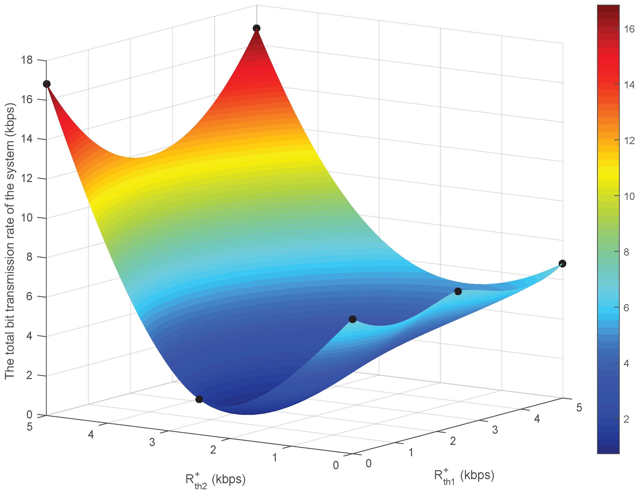
The numerical readout of Figure 7 reveals three characteristic regions. First, when R th 2 + = 0 kbps , the total capacity plateaus at 6.84 kbps ; increasing R th 1 + from 0 to 5 kbps within this range does not significantly affect the bit rate. Second, when the thresholds are set to intermediate values ( R th 1 + 2.5 kbps , R th 2 + = 2.5 kbps ), the system performance drops sharply to 1.79 kbps , creating a pronounced “U” valley; the residual interference from the defective SIC deals the heaviest blow here. Finally, when R th 2 + = 5 kbps is increased—whether R th 1 + = 0 kbps or 5 kbps —the total rate increases to 16.84 kbps , reaching its global peak. Therefore, the dominant performance determinant is the R th 2 + threshold; even high R th 1 + alone is not sufficient to accelerate the system, but when both thresholds are simultaneously high, the throughput remains around 16.84 kbps . In comparison, Figure 6 shows a gentle plateau limiting the capacity mainly to the threshold R th 2 + , while Figure 7 shows a deep “U” valley at moderate QoS demands and sharp peaks reaching 16.84 kbps when one threshold is kept high. In the imperfect SIC, optimization effectively puts the system in single-user mode by concentrating resources on a single connection that demands high QoS to avoid residual interference, thus achieving a total bit rate that exceeds the perfect SIC scenario, which has to share bandwidth and power.
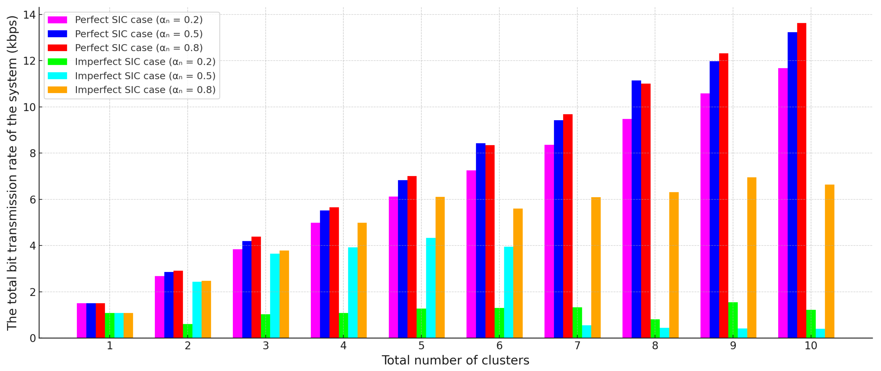
Figure 8 shows that as the number of clusters increases M, the total bit transmission rate increases steadily in the perfect SIC scenarios; however, a similar increase can be achieved in imperfect SIC only when α n 0.8 is chosen. For the same value of α n , perfect SIC offers higher performance at every point: For example, when M = 10 , the configuration of perfect SIC and α n = 0.8 reaches approximately 13.6 kbps , while imperfect SIC is only 6.6 kbps under the same power reflection coefficient. In the imperfect SIC settings running with lower α n values, the bit rate saturates or falls behind due to the increasing interference accumulation after M > 6 .
Figure 9 shows that as the output power of the base station P H decreases, the total bit transmission rate decreases logarithmically; on the other hand, as the noise power σ 2 is reduced to 10 2 , 10 3 and 10 4 W, the system performance increases at approximately the same rate. Under perfect SIC, when P H = 30 dBm, the rate is 6.5 × 10 4 bit/s, while when σ 2 = 10 4 W is selected at the same power, the value is 4.8 × 10 5 bit/s; under P H = 40 dBm and the lowest noise condition, the peak value increases to 8.7 × 10 5 bit/s. In the power-to-noise combination, the perfect SIC generally remains higher than the imperfect SIC; the difference reaches a significance level of 872 kbps vs. 638 kbps in the high-SNR region (40 dBm, σ 2 = 10 4 W), while this gap narrows to only a few kilobits/s under low transmission power and high noise conditions. These results show that the system capacity is determined by the base station power, channel noise, and SIC accuracy, respectively, and that these three parameters are of critical importance.
As seen in Figure 10, in perfect SIC scenarios, the total bit rate remains constant even if the coefficient z i changes; the rate depends on the stored energy and reaches approximately 6.83 , 7.68 , and 8.53 kbps for E i = 5 , 5.5 , and 6 mJ, respectively. In the imperfect SIC case, the initial bit rate is lower, but the performance gradually increases as z i becomes smaller (i.e., as the detection error decreases): for E i = 6 mJ, the bit rate increases from 5.16 kbps to 5.97 kbps; for E i = 5.5 mJ, it increases from 4.50 kbps to 5.26 kbps; and for E i = 5 mJ, it rises from 4.06 kbps to 4.42 kbps. However, the approximately 1.5 2.5 kbps gap between perfect and imperfect SIC remains at each energy level. In conclusion, although increasing the energy amount is the most effective way to boost total capacity, improving SIC accuracy still provides a noticeable performance gain, especially under high-energy conditions.
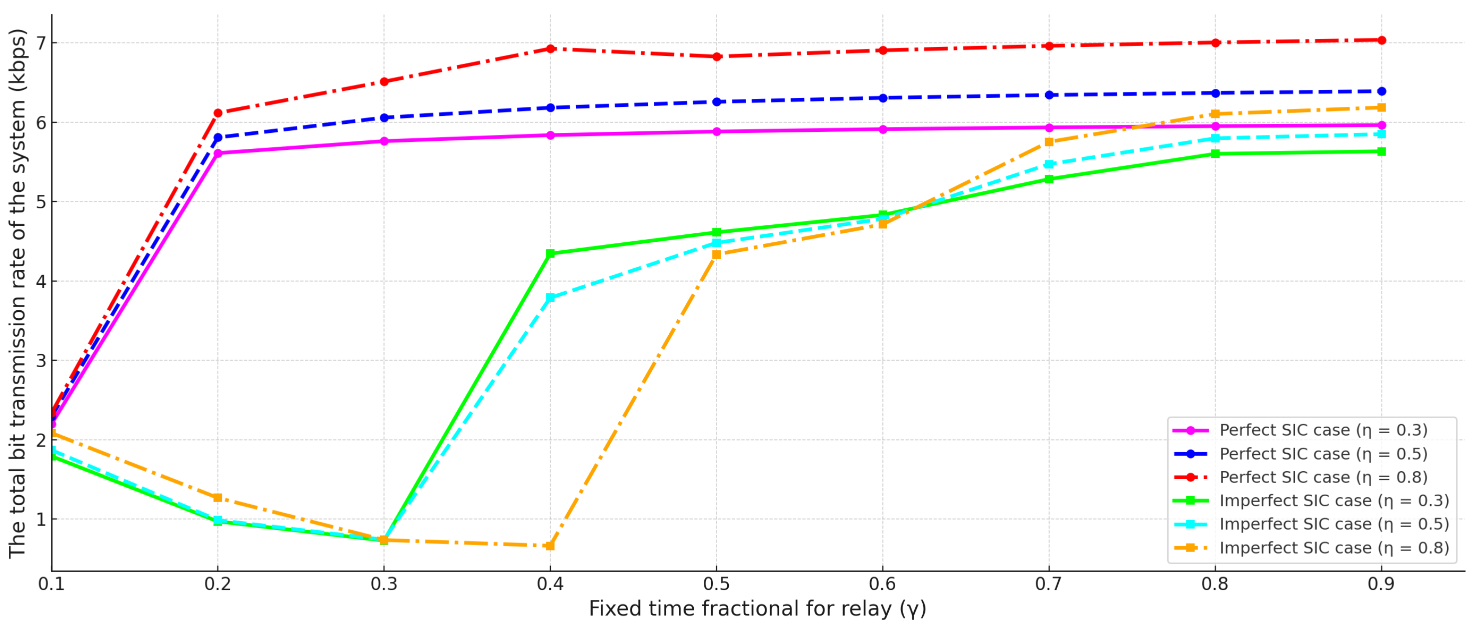
In Figure 11, when the fixed time allocated to the relay is small ( 0.1 ), the total bit transmission rate remains at around 2 kbps; when this rate increases to 0.2 , the speed suddenly jumps to the 5.5 –6 kbps band because the transmission time and energy-harvesting time are balanced. As the time margin is increased further, the increase slope slows down, and at 0.9 , the perfect SIC scenarios with 30, 50, and 80 percent energy-harvesting efficiency reach saturation at approximately 6.0 , 6.4 , and 7.0 kbps, respectively, for the 0.9 level. In the imperfect SIC scenarios, the speed decreases due to the increasing residual interference in the 0.1 0.3 range, reaching its lowest value at approximately 0.7 kbps at point 0.3 ; As the relay time margin increases, the energy flow increases, and the curve recovers rapidly, exceeding 6 kbps in the 0.8 0.9 range. These results demonstrate that keeping the relay time margin at medium–high values and improving energy-harvesting efficiency are critical for maximizing total capacity; furthermore, the performance loss due to imperfect SIC can be largely compensated for by sufficient transmission time.
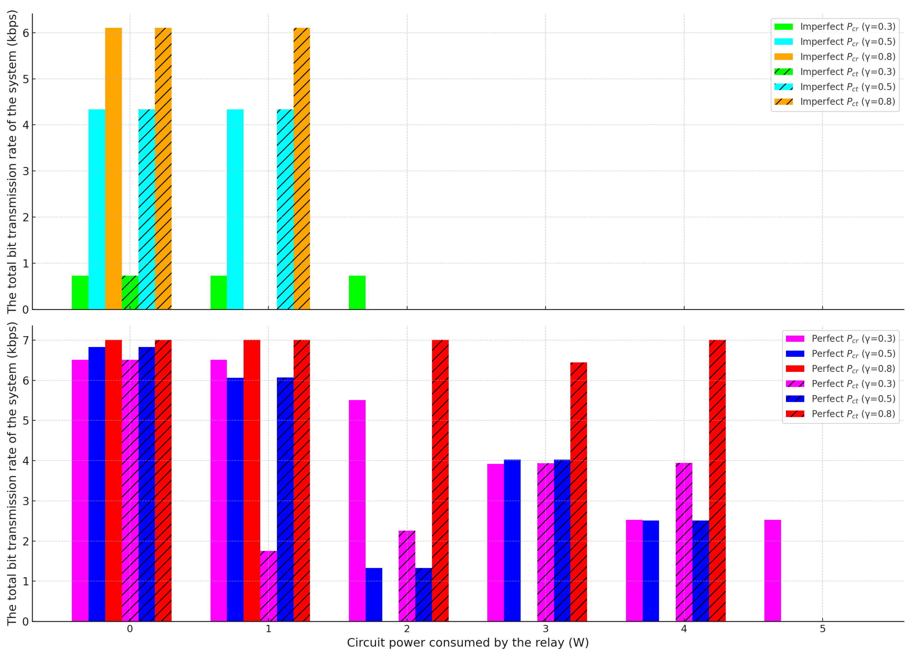
Figure 12 shows how the total bit transmission rate decreases as the power consumption of the relay’s receiver ( P cr ) and transmitter ( P ct ) circuits increases, and how this decrease varies depending on the fixed time fractional of relay margin γ and the SIC quality. In the perfect SIC scenario, circuit powers in the range of 0–1 W do not cause a significant capacity loss, while at γ = 0.8 , the speed is about 7 kbps, the γ = 0.5 configuration provides about 6.8 kbps at 0 W circuit power, and the γ = 0.3 configuration provides 6.5 kbps; when the transmitter circuit power is increased to 3 W, these speeds drop to 4.0 kbps and 3.9 kbps, respectively, and to 2.5 kbps at 4 W, and the system practically grinds to a halt at 5 W; when the same powers are applied to the receiver circuit, the γ = 0.8 configuration can still provide transmission around 2.5 kbps. With imperfect SIC, the system is much more fragile: the 6.1 kbps peak achieved with γ = 0.8 and 0–1 W circuit power rapidly drops to zero as P cr or P ct increases to 2 W; at γ = 0.5 , the critical threshold is 1 W, and at γ = 0.3 , only 0.7 kbps is initially achievable. The results show that the consumed circuit power is at a critical bottleneck, especially in the presence of residual interference, while the perfect SIC provides a tolerance window of about 3–4 W, providing a wider safety margin for the relay design.

5. Conclusions

This study presents the first optimization framework—stated as tractable constrained problems and solved numerically—for allocating time resources in multi-user, peer-assisted symbiotic radio networks based on the energy-harvesting TDMA/PD–NOMA architecture, establishing a new benchmark for 6G in the presence of obstacles and relays. Extensive simulations performed under typical 6G power levels, bandwidths, energy-harvesting efficiencies, reflection coefficients, reasonable relay time margins, and noise conditions clearly demonstrate that imperfect SIC limits the total throughput due to residual interference, while perfect SIC completely eliminates this limitation in the same environment, providing a significant capacity advantage. Furthermore, the conditions under which the performance gap between both SIC scenarios decreases are graphically illustrated.

Funding

This research received no external funding.

Institutional Review Board Statement

Not applicable.

Informed Consent Statement

Not applicable.

Data Availability Statement

The original contributions presented in this study are included in the article. Further inquiries can be directed to the corresponding author.

Conflicts of Interest

The author declares no conflicts of interest.

References

  1. Jawad, A.T.; Maaloul, R.; Chaari, L. A Comprehensive Survey on 6G and Beyond: Enabling Technologies, Opportunities of Machine Learning and Challenges. Comput. Netw. 2023, 237, 110085. [Google Scholar] [CrossRef]
  2. Ferrag, M.A.; Friha, O.; Kantarci, B.; Tihanyi, N.; Cordeiro, L.; Debbah, M.; Hamouda, D.; Al-Hawawreh, M.; Choo, K.K.R. Edge Learning for 6G-Enabled Internet of Things: A Comprehensive Survey of Vulnerabilities, Datasets, and Defenses. IEEE Commun. Surv. Tutor. 2023, 25, 2654–2713. [Google Scholar] [CrossRef]
  3. Giordani, M.; Polese, M.; Mezzavilla, M.; Rangan, S.; Zorzi, M. Toward 6G Networks: Use Cases and Technologies. IEEE Commun. Mag. 2020, 58, 55–61. [Google Scholar] [CrossRef]
  4. Pennanen, H.; Hänninen, T.; Tervo, O.; Tölli, A.; Latva-Aho, M. 6G: The Intelligent Network of Everything. IEEE Access 2025, 13, 1319–1421. [Google Scholar] [CrossRef]
  5. Onay, M.Y.; Ertug, O. Ambient Backscatter Communication Based Cooperative Relaying for Heterogeneous Cognitive Radio Networks. Radioengineering 2023, 32, 236–247. [Google Scholar] [CrossRef]
  6. Onay, M.Y.; Dulek, B. Performance Analysis of TV, FM and WiFi Signals in Backscatter Communication Networks. In Proceedings of the 27th Signal Processing and Communications Applications Conference (SIU), Sivas, Turkey, 24–26 April 2019; pp. 1–4. [Google Scholar] [CrossRef]
  7. Long, R.; Liang, Y.-C.; Guo, H.; Yang, G.; Zhang, R. Symbiotic Radio: A New Communication Paradigm for Passive Internet of Things. IEEE Internet Things J. 2020, 7, 1350–1363. [Google Scholar] [CrossRef]
  8. Onay, M.Y.; Dokmetas, B. 3D Printed Microstrip Antenna for Symbiotic Communication: WiFi Backscatter and Bit Rate Evaluation for IoT. Internet Things 2025, 32, 101643. [Google Scholar] [CrossRef]
  9. Alsabah, M.; Naser, M.A.; Mahmmod, B.M.; Abdulhussain, S.H.; Eissa, M.R.; Al-Baidhani, A.; Noordin, N.K.; Sait, S.M.; Al-Utaibi, K.A.; Hashim, F. 6G Wireless Communications Networks: A Comprehensive Survey. IEEE Access 2021, 9, 148191–148243. [Google Scholar] [CrossRef]
  10. Kim, N.; Kim, G.; Shim, S.; Jang, S.; Song, J.; Lee, B. Key Technologies for 6G-Enabled Smart Sustainable City. Electronics 2024, 13, 268. [Google Scholar] [CrossRef]
  11. Zhang, R.; Kang, X.; Liang, Y.-C. Minimum Throughput Maximization for Peer-Assisted NOMA-Plus-TDMA Symbiotic Radio Networks. IEEE Wirel. Commun. Lett. 2021, 10, 1847–1851. [Google Scholar] [CrossRef]
  12. Li, D. Backscatter Communication via Harvest-Then-Transmit Relaying. IEEE Trans. Veh. Technol. 2020, 69, 6843–6847. [Google Scholar] [CrossRef]
  13. Li, M.; Huang, Y.; Yu, F.R.; Si, P.; Zhang, H. Ambient Backscatter Communication-Assisted Intelligent Resource Management for Green Industrial IoT. IEEE Wirel. Commun. 2025, 32, 174–181. [Google Scholar] [CrossRef]
  14. Liu, W.; Shen, S.; Tsang, D.H.K.; Murch, R. MIMO Ambient Backscatter Communications: Capacity Maximization and Beamforming Optimization. IEEE Trans. Veh. Technol. 2023, 72, 15829–15843. [Google Scholar] [CrossRef]
  15. Wang, W.-J.; Xu, K.; Yan, Y.; Chen, L. Relay Selection-Based Cooperative Backscatter Transmission With Energy Harvesting: Throughput Maximization. IEEE Wirel. Commun. Lett. 2022, 11, 1533–1537. [Google Scholar] [CrossRef]
  16. Zhang, Y.; Peng, M.; Liu, Y.; Jiang, T. Distributed MIMO Assisted Battery-Free Backscatter Communications for Ambient Internet of Things. IEEE Internet Things Mag. 2025, 8, 40–46. [Google Scholar] [CrossRef]
  17. Fang, Z.; Li, Q.; Liu, J.; Zhou, J.; Shen, S. Beamforming Design for Multi-Antenna Multi-Tag Symbiotic Radio Backscatter Systems. AEU Int. J. Electron. Commun. 2023, 170, 154820. [Google Scholar] [CrossRef]
  18. Chen, X.; Xu, D.; Zhu, H. Cooperative Resource Allocation for Hybrid NOMA-OMA-Based Wireless Powered MC-IoT Systems with Hybrid Relays. Electronics 2024, 13, 99. [Google Scholar] [CrossRef]
  19. Asif, M.; Ihsan, A.; Khan, W.U.; Ranjha, A.; Zhang, S.; Wu, S.X. Energy-Efficient Beamforming and Resource Optimization for AmBSC-Assisted Cooperative NOMA IoT Networks. IEEE Internet Things J. 2023, 10, 12434–12448. [Google Scholar] [CrossRef]
  20. Xie, X.; Ding, Z. Backscatter-Assisted Non-Orthogonal Multiple Access Network for Next Generation Communication. IET Signal Process. 2023, e12211. [Google Scholar] [CrossRef]
  21. Ahmed, M.; Khan, W.U.; Ihsan, A.; Li, X.; Li, J.; Tsiftsis, T.A. Backscatter Sensors Communication for 6G Low-Powered NOMA-Enabled IoT Networks Under Imperfect SIC. IEEE Syst. J. 2022, 16, 5883–5893. [Google Scholar] [CrossRef]
  22. Alkhawatrah, M. Energy-Harvesting Cooperative NOMA in IoT Networks. Model. Simul. Eng. 2024, 1043973. [Google Scholar] [CrossRef]
  23. Khavari-Moghaddam, S.; Farahmand, S.; Razavizadeh, S.M.; Lee, I. Optimum Solutions for Weighted Sum-Rate of NOMA and TDMA in Wireless-Powered IoT Networks. IEEE Internet Things J. 2024, 11, 3302–3315. [Google Scholar] [CrossRef]
  24. Samanta, D.; De, C.K.; Chandra, A. Performance Analysis of NOMA Based Hybrid Cognitive Radio Network Assist by Full-Duplex Relay. Telecommun. Syst. 2025, 88, 37. [Google Scholar] [CrossRef]
  25. Özduran, V.; Nomikos, N.; Nasab, E.S.; Ansari, I.S.; Trakadas, P. Relay-Aided Uplink NOMA Under Non-Orthogonal CCI and Imperfect SIC in 6G Networks. IEEE Open J. Veh. Technol. 2024, 5, 658–680. [Google Scholar] [CrossRef]
  26. Zhang, Q.; Zhang, L.; Liang, Y.-C.; Kam, P.-Y. Backscatter-NOMA: A Symbiotic System of Cellular and Internet-of-Things Networks. IEEE Access 2019, 7, 20000–20013. [Google Scholar] [CrossRef]
  27. Zhao, W.; Zhu, J.; Yang, B.; She, X.; Wang, G.; Tellambura, C. Outage Analysis of Hybrid Backscatter Communication Systems With Opportunistic SIC. IEEE Wirel. Commun. Lett. 2023, 12, 2163–2167. [Google Scholar] [CrossRef]
  28. Ding, H.; Alouini, M.-S.; Xin, K.; Li, H.; Xu, S. Symbiotic Ambient Backscatter Systems: Outage Behavior and Ergodic Capacity. IEEE Internet Things J. 2022, 9, 23670–23690. [Google Scholar] [CrossRef]
  29. Yang, H.; Ding, H.; Elkashlan, M.; Li, H.; Xin, K. A Novel Symbiotic Backscatter-NOMA System. IEEE Trans. Veh. Technol. 2023, 72, 11006–11011. [Google Scholar] [CrossRef]
  30. Onay, M.Y. Dynamic Time Allocation Based Physical Layer Security for Jammer-Aided Symbiotic Radio Networks. Radioengineering 2024, 33, 442–451. [Google Scholar] [CrossRef]
  31. Onay, M.Y. Secrecy Rate Maximization for Symbiotic Radio Network with Relay-Obstacle. Int. J. Comput. Exp. Sci. Eng. 2024, 10, 381–387. [Google Scholar] [CrossRef]
  32. Onay, M.Y. Secrecy Rate Performance Analysis of Jammer-Aided Symbiotic Radio with Sensing Errors for Fifth Generation Wireless Networks. Appl. Sci. 2025, 15, 289. [Google Scholar] [CrossRef]
  33. Yeganeh, R.S.; Omidi, M.J.; Ghavami, M. Multi-BD Symbiotic Radio-Aided 6G IoT Network: Energy Consumption Optimization with QoS Constraint Approach. IEEE Trans. Green Commun. Netw. 2023, 7, 2067–2080. [Google Scholar] [CrossRef]
  34. Liang, Y.-C.; Zhang, Q.; Larsson, E.G.; Li, G.Y. Symbiotic Radio: Cognitive Backscattering Communications for Future Wireless Networks. IEEE Trans. Cogn. Commun. Netw. 2020, 6, 1242–1255. [Google Scholar] [CrossRef]
  35. Li, F.; Sun, Q.; Chen, X.; Dang, S.; Zhang, J.; Wong, K.-K. Rate-Splitting Assisted Cell-Free Symbiotic Radio: Channel Estimation and Transmission Scheme. IEEE Trans. Commun. 2025, 73, 5313–5327. [Google Scholar] [CrossRef]
  36. Bisen, S.; Jose, J.; Ding, Z.; Choi, K.; Bhatia, V. On Performance of Backscatter-NOMA Systems: Symbiotic Communication for IoT Devices. IEEE Trans. Veh. Technol. 2024, 73, 15854–15859. [Google Scholar] [CrossRef]
  37. Fang, Z.; Wu, Z.; Ni, W.; Wang, X.; Hossain, E. Beamforming Design for Novel Relay-Assisted Multi-User Multi-Tag Symbiotic Radios. IEEE Wirel. Commun. Lett. 2023, 12, 2253–2257. [Google Scholar] [CrossRef]
  38. Jin, N.; Yang, G.; Liang, Y.C.; Fu, S.; Chen, X. Joint Beamforming and Backscatter Communication Design for Symbiotic Radio Networks. IEEE Internet Things J. 2023, 10, 19441–19453. [Google Scholar] [CrossRef]
  39. Al-Nahari, A.; Jäntti, R.; Zheng, G.; Mishra, D.; Nie, M. Ergodic Secrecy Rate Analysis and Optimal Power Allocation for Symbiotic Radio Networks. IEEE Access 2023, 11, 82327–82337. [Google Scholar] [CrossRef]
  40. Liang, W.; Wen, S.; Ng, S.X.; Zhang, J. Utility-Based Cooperative Resource Sharing in Symbiotic-Radio-Aided Internet of Things Networks. IEEE Internet Things J. 2022, 10, 19368–19384. [Google Scholar] [CrossRef]
  41. Wang, J.; Ding, X.; Zhang, Q.; Liang, Y.C. Multiple Access Design for Symbiotic Radios: Facilitating Massive IoT Connections with Cellular Networks. IEEE Trans. Wirel. Commun. 2023, 23, 201–216. [Google Scholar] [CrossRef]
  42. Guo, Y.; Wang, G.; Xu, R.; He, R.; Wei, X.; Tellambura, C. Capacity Analysis for Wireless Symbiotic Communication Systems with BPSK Tags Under Sensitivity Constraint. IEEE Commun. Lett. 2022, 26, 44–48. [Google Scholar] [CrossRef]
  43. Ma, Z.; Zhang, R.; Ai, B.; Lian, Z.; Zeng, L.; Niyato, D.; Peng, Y. Deep Reinforcement Learning for Energy Efficiency Maximization in RSMA-IRS-Assisted ISAC System. IEEE Trans. Veh. Technol. 2025, 1–6. [Google Scholar] [CrossRef]
  44. Liu, L.; Ai, B.; Niu, Y.; Han, Z.; Wang, N.; Ma, Z.; Xiong, L. STAR-RIS Assisted Train-to-Ground Communications in Space-Air-Ground Integrated Networks. IEEE Trans. Commun. 2025, 1. [Google Scholar] [CrossRef]
  45. Dong, E.; Lian, Z.; Wang, Y.; Ma, Z.; Ling, L.; Luo, C. Double-IRS Auxiliary Communications: Models and Performance Prediction. IEEE Wirel. Commun. Lett. 2024, 13, 2571–2575. [Google Scholar] [CrossRef]
  46. Lyu, B.; Yang, Z.; Gui, G.; Sari, H. Optimal Time Allocation in Backscatter Assisted Wireless Powered Communication Networks. Sensors 2017, 17, 1258. [Google Scholar] [CrossRef]
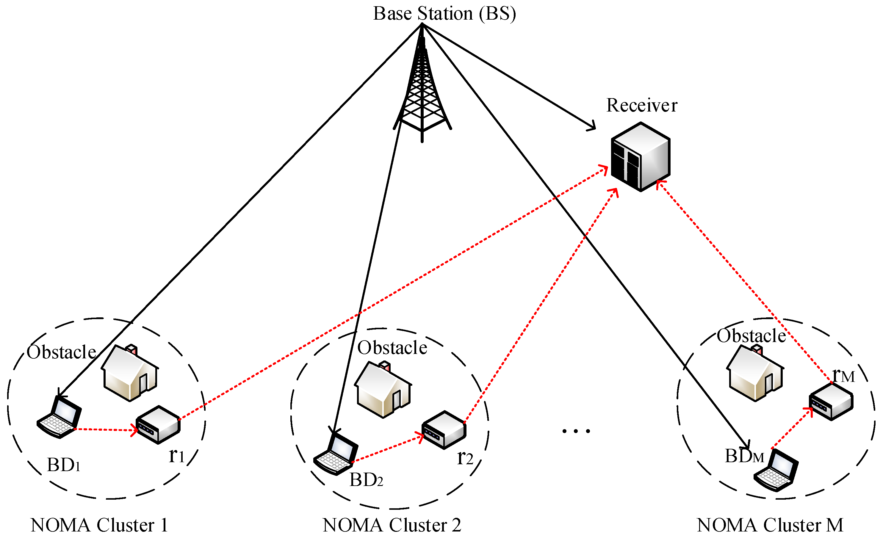
Figure 1. System architecture of the NOMA network comprising multiple user clusters, dedicated relays, and obstacles.
Applsci 15 09504 g001
Figure 2. Periodic structure for two-cluster peer-assisted NOMA communication.
Applsci 15 09504 g002
Figure 3. Periodic structure for multi-cluster peer-assisted NOMA communication.
Applsci 15 09504 g003
Figure 4. Block diagram of the BDn terminal with energy-harvesting and power management components.
Applsci 15 09504 g004
Figure 5. Block diagram of the r n terminal with signal-decoding, information-forwarding, and energy-harvesting functionalities.
Applsci 15 09504 g005
Figure 6. Relationship between R sum T 2 (total bits in T 2 ) and the QoS thresholds R th 1 + (minimum bits in T 1 ) and R th 2 + (per-BD) under perfect SIC. A broad 7.3 kbps plateau appears at R th 2 + = 0 , with R th 1 + non-binding over 0–5 kbps; increasing R th 2 + (e.g., to 2.5 kbps) induces a marked capacity drop—hence, throughput is dominantly governed by R th 2 + .
Applsci 15 09504 g006
Figure 7. R sum T 2 versus R th 1 + and R th 2 + under imperfect SIC. A plateau appears at R th 2 + = 0 ; at moderate thresholds residual interference forms a pronounced `U’ valley; at high R th 2 + a global peak emerges largely independent of R th 1 + . R th 2 + dominates; the optimizer concentrates resources on a single high-QoS link.
Applsci 15 09504 g007
Figure 8. Total bit rate R sum T 2 versus the number of clusters M for different power reflection coefficients α n under perfect vs. imperfect SIC. With perfect SIC, the rate increases steadily; with imperfect SIC, similar growth appears only when α n 0.8 , while for smaller α n the rate saturates or degrades after M > 6 due to residual-interference accumulation.
Applsci 15 09504 g008
Figure 9. R sum T 2 versus BS power P H and noise power σ 2 under perfect vs. imperfect SIC. Lower P H causes a logarithmic drop, while reducing σ 2 from 10 2 to 10 4 W yields a comparable gain. Perfect SIC dominates at high SNR; the gap narrows at low power/high noise.
Applsci 15 09504 g009
Figure 10. R sum T 2 versus initial energy E i and imperfect-SIC coefficient z i . With perfect SIC, the rate is z i -insensitive and grows with E i ; with imperfect SIC, it increases as z i decreases. Across all E i , perfect SIC remains consistently higher. Capacity is primarily driven by E i ; improving SIC accuracy yields additional gains, especially at high E i .
Applsci 15 09504 g010
Figure 11. Performance variation in the system with respect to the relays’ fixed time fractional parameter under different energy-harvesting efficiencies: keeping the relay time share at medium–high levels and improving energy-harvesting efficiency are critical to maximize total capacity; moreover, the performance loss due to imperfect SIC can be largely mitigated by sufficient transmission time.
Applsci 15 09504 g011
Figure 12. Variation in the system’s total bit transmission rate with respect to the relay’s circuit power consumption under perfect and imperfect SIC conditions: as the relay receiver/transmitter circuit powers P C r and P C t increase, the total bit rate R sum T 2 declines, with the slope governed by the time margin γ and SIC quality. Perfect SIC offers a tolerance window of about 3 4 W (wider safety margin), whereas imperfect SIC is fragile and can collapse at much lower circuit powers. Therefore, it is wise to limit the circuit power and keep γ at medium–high levels to preserve capacity.
Applsci 15 09504 g012
Table 1. List of symbols.
SymbolMeaning
T 1 TDMA phase duration; T 1 = j = 0 M τ j .
T 2 PD–NOMA data-phase duration; T 2 = λ .
TFrame duration; T = T 1 + T 2 = 1 .
τ j jth time slot within T 1 ( j = 0 , , M ).
τ Time slot vector within T 1 : τ = τ 0 , τ 1 , , τ M T .
λ Time duration of T 2 .
MNumber of clusters/relays/BDs.
nCluster/relay/BD index ( 1 n M ).
η Energy-harvesting efficiency.
γ Fixed time fractional.
α n Power reflection coefficient of BD n .
z i Imperfect-SIC coefficient (residual-interference factor).
P H BS transmit power.
P C r , P C t Relay receiver/transmitter circuit powers.
E i , E c Initial energy/total energy consumed by the relay.
σ 2 Noise power.
BBandwidth.
h bs rc BS → receiver channel gain.
g bs r n BS → relay n ( r n ) channel gain.
g r n rc Relay n receiver channel gain.
h n BS BD n channel gain.
g n BD n   r n channel gain.
ϵ Performance gap factor.
V j , n The channel gain between B D n and B D j .
R th 1 + Minimum bit target over T 1 (QoS).
R th 2 + Per-BD QoS threshold.
Disclaimer/Publisher’s Note: The statements, opinions and data contained in all publications are solely those of the individual author(s) and contributor(s) and not of MDPI and/or the editor(s). MDPI and/or the editor(s) disclaim responsibility for any injury to people or property resulting from any ideas, methods, instructions or products referred to in the content.