1. Introduction
Permanent magnet synchronous motors (PMSMs) are widely used in high-performance servo drive systems—including power transmission, electric vehicles, CNC machine tools, and aerospace applications—due to their compact size, high efficiency, and high power density [
1]. However, PMSMs inherently experience various disturbances stemming from their internal structure and external driving sources, which limit their overall performance. These disturbances can be broadly categorized into non-periodic and periodic types [
2]. Non-periodic disturbances mainly arise from dq-axis coupling, parameter changes, and fluctuations in external loads. The extent of cross-coupling depends on factors such as motor speed, dq-axis currents, and inductance. Under conditions of heavy load and high speed, changes in the magnetic circuit characteristics cause inductance to vary over time, leading to significant uncertainties in the cross-coupling terms [
3]. Periodic disturbances, conversely, are largely caused by imperfections in motor structural design and nonlinearities in the inverter [
4,
5]. For instance, the commonly used tile-shaped permanent magnet configuration [
6] produces 6n ± 1 spatial harmonics in the air-gap flux density, which in turn generate corresponding current harmonics and torque ripple at the 6n order. Likewise, inverter dead-time effects introduce odd-order harmonics such as the 5th, 7th, 11th, and 13th. Experimental results show that harmonic amplitudes decrease as frequency increases, with the 5th and 7th harmonics having the most significant impact (10.1% and 4.13%, respectively), while the 11th and 13th harmonics contribute 1.0% and 0.3%, respectively [
7]. Consequently, it is crucial to develop a PMSM control approach that effectively mitigates both non-periodic and periodic disturbances.
Methods for suppressing non-periodic disturbances primarily include sliding mode control, disturbance observer control, and active disturbance rejection control. In [
8], a fractional-order PID controller utilizing a multi-objective optimization algorithm was presented, enhancing the system′s dynamic response and improving disturbance rejection. Reference [
9] developed a combined framework featuring a robust speed controller and a load observer, integrating composite nonlinear feedback and integral sliding mode techniques to boost transient response and robustness, respectively. A sliding mode observer was employed to mitigate unknown disturbances, while feedforward compensation was used to cancel disturbances. In [
10], improvements to the extended state observer were made and applied to current loop decoupling, effectively suppressing both DC and AC disturbances. Reference [
11] introduced a cascaded disturbance observer structure to estimate disturbances in quadrotor systems experiencing multiple time-varying delays, simultaneously eliminating delay effects. Reference [
12] concentrated on theoretical progress in anti-disturbance control by designing an adaptive switching gain observer that dynamically adjusts gain parameters, significantly enhancing robustness against time-varying disturbances. In [
13], a novel cascaded extended state observer framework was created to estimate disturbance uncertainties, accompanied by a control law based on state error feedback, overcoming the traditional trade-off between control performance and noise immunity associated with large gain bandwidth ESOs. Finally, in [
14], an extended state observer based on a generalized integrator was proposed for grid-connected systems, demonstrating excellent performance in detecting periodic disturbances.
Methods for suppressing periodic disturbances primarily include harmonic voltage compensation, multi-rotational PI control, repetitive control, proportional–resonant control, and iterative learning control. In reference [
15], a passivity-based control approach utilizing interconnection and damping assignment was introduced to handle time-varying external disturbances. Reference [
16] used a three-parameter notch filter to extract harmonic currents in open-winding PMSM systems sharing a common DC bus, combined with feedforward voltage compensation. Reference [
17] applied repetitive control to reduce harmonics at specific frequencies; however, the controller must be redesigned if the harmonic frequency changes. In [
18], a proportional–resonant controller was implemented in parallel with a PI controller to reduce harmonics. This approach is simple and easy to tune, but has limited disturbance rejection capability and generally requires combination with other methods for improved performance. Reference [
19] proposed an adaptive-frequency harmonic suppression technique based on vector reconstruction to minimize current measurement errors; however, its computational complexity limits practical use. Reference [
20] presented a method combining an iterative learning disturbance observer with second-order sliding mode control to enhance robustness and reduce torque ripple in PMSM speed regulation systems. Reference [
21] introduced a current control strategy based on a linear extended state observer with measurement delay compensation, accounting for parameter variations, dead-time effects, and unmodeled dynamics to improve current loop dynamic performance. Reference [
22] proposed a parallel structure integrating vector resonant control with active disturbance rejection control for linear PMSM systems, effectively suppressing current harmonics and enhancing disturbance rejection. Reference [
23] developed an improved predictive fractional-order iterative learning control method to mitigate disturbances in linear PMSM by enhancing amplitude and phase compensation, thereby broadening the learnable frequency range and further optimizing disturbance rejection. Reference [
24] devised a voltage feedforward compensation strategy for sensorless control, employing iterative learning control (ILC) to calculate harmonic compensation caused by inverter nonlinearities and current bias online, combined with a lookup-table storage mechanism, effectively eliminating back-EMF estimation errors. Regarding the problem of common-mode voltage generation in voltage inverters, reference [
25] presents a new active common-mode elimination (ACME) modulation method for three-level midpoint clamped (3L-NPC) inverters. This method is based on the improved space vector modulation (MSVM), and a new power circuit system is designed between the inverter and the induction motor. This power circuit system completely eliminates the common-mode voltage, improves the utilization rate of the DC bus voltage, and reduces voltage harmonics.
The article is organized as follows: To effectively suppress both non-periodic and periodic disturbances in PMSM drive systems, this paper introduces a current disturbance rejection approach based on a resonant control periodic disturbance observer (RC-PDOB). First, all dq-axis coupling terms and parameter uncertainties are combined into a single lumped disturbance, allowing for an observer-based decoupled model that inherently cancels flux–current interactions and reduces the effects of electrical parameter variations on non-periodic disturbances. Next, to address the limitation of traditional disturbance observers (DOB) in handling periodic components, resonant compensators are integrated directly into the observer design, enabling accurate suppression of periodic disturbances across multiple harmonic frequencies. Finally, the effectiveness of the proposed method is demonstrated through experimental validation.
The novelty of the RC-PDOB is threefold:
(1) Integrated resonant control and disturbance observer approach: This method incorporates a proportional–resonant (PR) controller within the low-pass filter stage of the disturbance observer to selectively reduce periodic harmonics (like the 6th and 12th), effectively addressing the bandwidth constraints of traditional disturbance observers. While cascaded disturbance observers can broaden bandwidth and enhance disturbance estimation, they still struggle to effectively detect medium- and high-frequency disturbances. In comparison to iterative learning control, resonant control features a simpler design, is less sensitive to system delays, streamlines the control algorithm, and offers better suppression of disturbances at specific harmonic frequencies.
(2) Simultaneous management of multiple harmonic components: The proposed approach uses cascaded resonant terms to include both the 6th and 12th harmonic frequencies within a single observer structure, addressing the drawback of repetitive control methods that need controller redesign for each specific frequency. While the vector-reconstruction-based adaptive frequency harmonic suppression algorithm can eliminate disturbances at unknown frequencies, its high computational demands restrict its practical use.
(3) Improved parameter robustness: The proposed approach considers coupling effects and parameter variations as components of an overall disturbance and compensates for them using a disturbance observer. This eliminates the heavy reliance on precise inductance parameters that traditional decoupling methods, like feedback decoupling, demand for accurate parameter matching.
2. Disturbance Observer Model for dq-Axis Current Decoupling in Permanent Magnet Synchronous Motors
2.1. Mathematical Model of the PMSM Current Loop Under Disturbances
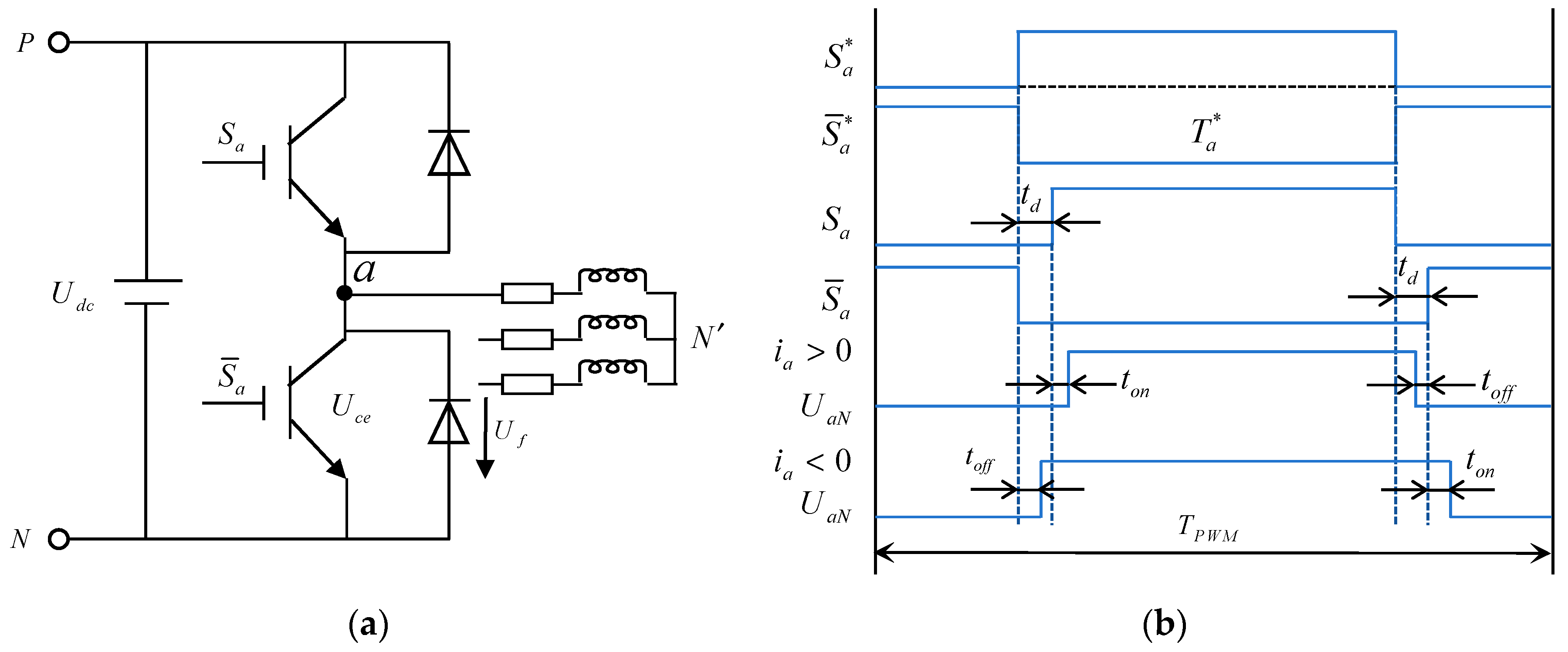
Figure 1a shows the equivalent schematic diagram of the three-phase permanent magnet synchronous motor.
Figure 1b shows the schematic diagram of the inverter′s dead zone effect including the ideal and actual drive signals for the upper and lower bridge arms of phase A, as well as the voltage of phase A.
In
Figure 1a,
Udc represents the DC bus voltage,
Uce represents the IGBT conduction voltage drop, and
Uf represents the voltage drop across the freewheeling diode.
Figure 1b illustrates the ideal and actual gate drive signals for the upper and lower switches of Phase A, as well as the corresponding Phase-A output voltage waveform. Here,
TPWM denotes the carrier period,
td is the dead time,
ton and
toff represent the turn-on and turn-off durations of the switching devices, and
indicates the ideal conduction time of the Phase-A switch after pulse-width modulation (PWM).
Within a single PWM period, the Phase-A voltage error caused by the inverter dead-time effect can be expressed as:
By performing a Fourier series expansion of Equation (1), the following expression is obtained:
Therefore, it can be concluded that the error voltage caused by the inverter′s nonlinear behavior results in distortion of the output voltage waveform, mainly appearing as a series of odd-order harmonics of the form 6n ± 1. To simplify calculations, the mathematical model of the inverter output voltage is further converted into the synchronous rotating reference frame.
where Δ
ud and Δ
uq represent the voltage distortions along the d-axis and q-axis, respectively;
ud0 and
uq0 represent the DC components of the dq-axis voltage errors;
ud6,
ud12,
uq6,
uq12 are the amplitudes of the 6th and 12th harmonic components in the d-q-axes, respectively;
θd6,
θd12,
θq6,
θq12 are the corresponding phase angles of these harmonics. Since harmonic amplitudes decrease with increasing harmonic order, only the prominent 6th and 12th harmonics are considered in the dq frame. These voltage distortions can lead to discrepancies between the inverter-applied voltage and the output voltage of the current control loop, resulting in current harmonics and degraded system performance.
Figure 2 illustrates the PMSM system structure with disturbances.
KPWM denotes the equivalent gain of the inverter, and
TPWM indicates the equivalent delay time of the inverter.
During the operation of a permanent magnet synchronous motor (PMSM), the current control loop is subject to two main types of disturbances: non-periodic and periodic disturbances. Non-periodic disturbances primarily include uncertainties in electrical parameters, external disturbances, and coupling between the dq-axis currents. Periodic disturbances mainly arise from flux linkage harmonics and inverter dead-time effects. In the rotor reference frame, the current loop equations of the PMSM can be expressed as:
where
ud,
uq represent the d-axis and q-axis voltages,
id,
iq are the d-axis and q-axis currents,
Rs is the stator resistance,
Ψf is the rotor permanent magnet flux linkage,
Ld,
Lq are the d-axis and q-axis inductances, and
ωe is the electrical angular speed of the rotor.
fid and
fiq, respectively, represent the total disturbance within the dq-axis of the current loop.
dddead,
dqdead represent the periodic current disturbances in the dq-axis caused by inverter dead-time voltage distortion,
ddflux,
dqflux represent the periodic disturbances caused by air-gap flux linkage harmonics,
ddp,
dqp are disturbances resulting from variations in electrical parameters,
dd,
dq are unmodeled system disturbances.
Because of the motor′s structural design, the permanent magnet flux linkage produces odd-order harmonics, which in turn create 6n-order harmonics in the dq-axis. Additionally, the inverter′s dead-time effect introduces voltage distortion in the dq-axis. These voltage distortions can cause a discrepancy between the inverter′s applied voltage and the output voltage from the current control loop, resulting in 6n-order current harmonics in the dq-axis and reducing overall system performance. As mentioned in [
6], the amplitudes of harmonics from these two sources decrease as their order increases, being inversely proportional to harmonic order. Therefore, only the primary 6th and 12th harmonics are taken into account in the dq reference frame.
2.2. dq-Axis Decoupling Model of the PMSM Current Loop Based on a Disturbance Observer
In the synchronous rotating reference frame, the voltage equations of the PMSM along the d- and q-axes can be expressed as:
The dq-axis voltage equations contain coupling terms that are proportional to the inductance, current, and rotational speed, as well as disturbance terms related to the flux linkage and speed. These coupling terms intensify fluctuations in the dq-axis currents. In this study, such coupling terms are regarded as non-periodic disturbances within the current control loop.
To reduce the impact of parameter variations that cause non-periodic disturbances in the system, this study investigates a decoupling method for the PMSM current loop control model based on a disturbance observer. In Equation (6), the coupling terms, flux linkage terms, parameter uncertainties, external disturbances, and unmodeled dynamics are all considered as non-ideal and unmeasurable external disturbances. By aggregating these effects into a single total disturbance, Equation (6) can be rewritten as:
where
fd(
t),
fq(
t) represent the total disturbances in the d-axis and q-axis,
R′s and
L′s represent the nominal Resistance and nominal Inductance, the formulation can be expressed as:
where ∆
Rs =
Rs −
R′s, ∆
Ls =
Ls =
L′s represent the uncertainties in resistance and inductance.
The ideal DOB models for the d-axis and q-axis of the PMSM can be expressed as:
In practical applications, considering system protection requirements and the limited capacity of the inverter, the dq-axis currents id(t), iq(t), as well as the output voltages ud(t), uq(t) are all bounded. Consequently, the derivatives of id(t), iq(t) are bounded, the total disturbances fdDOB(t), fqDOB(t), and their derivatives are also bounded. This implies that the outputs of the disturbance observer are bounded, satisfying the convergence condition of the DOB.
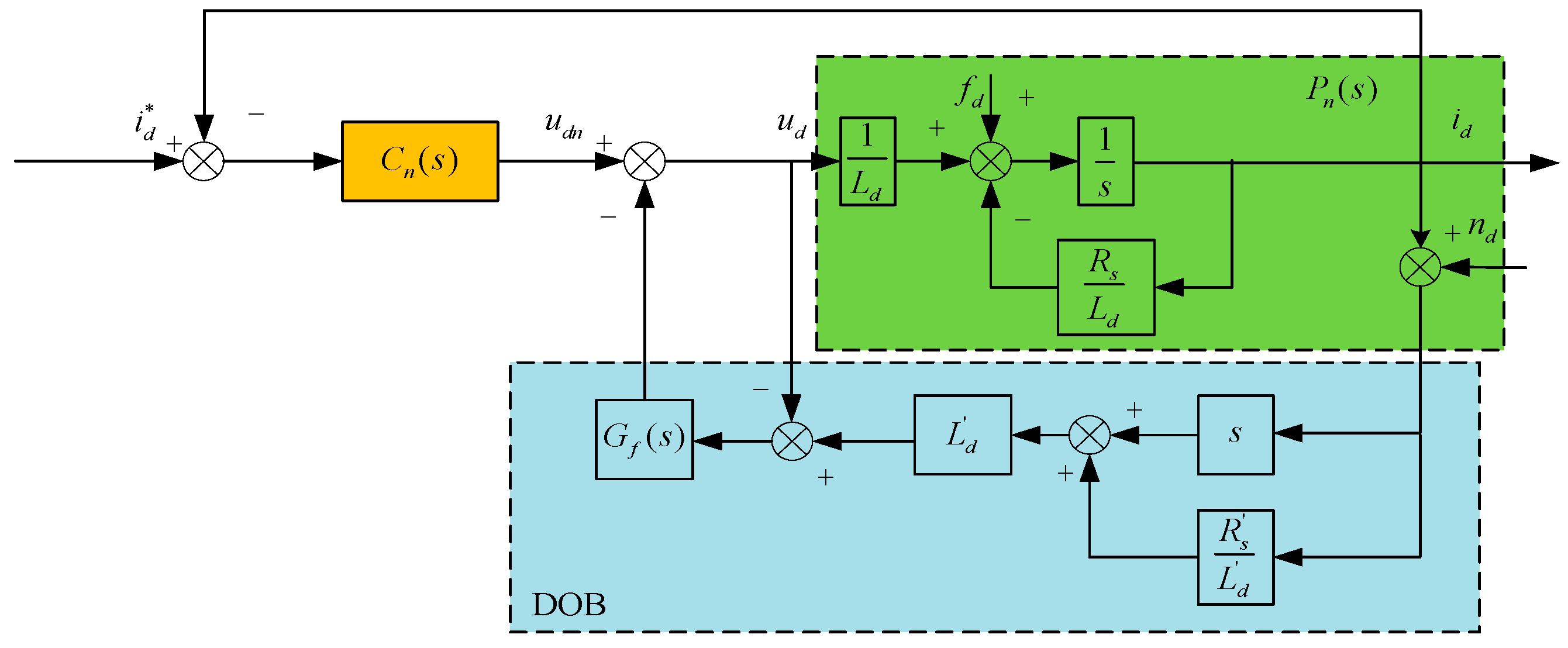
From the above analysis, it can be seen that a disturbance-observer-based control system consists of two control loops: an outer loop formed by current feedback and an inner loop based on disturbance estimation and compensation via the DOB. The outer loop is primarily responsible for system tracking and stabilization, while the inner loop is dedicated to disturbance observation and compensation. Accordingly, a current loop control structure for the PMSM can be designed. Taking
id as an example, a two-degree-of-freedom control system is illustrated in
Figure 3.
To ensure proper matching in disturbance compensation, a gain
Ld′ is introduced.
Gf(
s) represents a first-order Butterworth filter, where
Gf(
s) =
ωc/s +
ωc,
ωc is the cutoff frequency of the filter.
nd represents the system measurement noise. Then, the disturbance estimate obtained by the DOB is expressed as:
Taking the d-axis as an example, the residual disturbance after compensation can be calculated as:
From the above equation, it can be seen that when the cutoff frequency ωc of the filter Gf(s) approaches zero (ωc→0), the residual disturbance ∆fd→fd, meaning no disturbance compensation is applied, and the system operates in open-loop mode. When the cutoff frequency approaches infinity (ωc→+∞), ∆fd→0, indicating that the disturbance is completely suppressed. The above analysis shows that the disturbance observation performance of the ideal DOB does not depend on the accuracy of the system model parameters, but rather on the cutoff frequency of the low-pass filter.
2.3. Simulink-Based Analysis of Decoupling Capability and Non-Periodic Disturbance Rejection
To verify the effectiveness of the proposed DOB-based decoupling method and its capacity to suppress non-periodic disturbances, three distinct current loop decoupling control systems were developed: PI linear feedback decoupling, ESO-based decoupling, and DOB-based decoupling. The disturbance rejection performance of these three algorithms was evaluated under both matched and mismatched inductance parameter scenarios. The motor simulation parameters, corresponding to a surface-mounted PMSM, are provided in
Table 1.
Set the simulation step size to 10−6 s, and the operating frequency of the current loop to 10 kHz. Since both the motor and the inverter in the simulation are ideal models, to enhance the comparability, the dead time of the three-phase inverter is increased to 2 us. The PI control parameters are set as Kp = 50 rad/s and Ki = 1000 rad/s. The ESO adopted a linear extended state observer with gain coefficients β1 = 4000 rad/s and β2 = 20002 rad/s. The DOB bandwidth parameter is set to ωc = 1000 rad/s.
First, the case of matched inductance parameters is considered (
L =
Ls). When a 5 N·m load is suddenly applied at 0.2 s, the dq-axis current responses under three decoupling strategies are obtained, as shown in
Figure 4. Under PI linear decoupling (
Figure 4a), a step change in the q-axis current causes a 0.4 A fluctuation in the d-axis current lasting 34 ms, with a q-axis overshoot of 1.1 A and a steady-state error of 0.32 A. With ESO decoupling (
Figure 4b), the d-axis fluctuation is reduced to 0.35 A for 27 ms, while the q-axis overshoot and steady-state error decrease to 0.81 A and 0.30 A, respectively. In contrast, DOB decoupling (
Figure 4c) achieves the best performance, with only a 0.25 A fluctuation lasting 26 ms, a q-axis overshoot of 0.40 A, and a steady-state error of 0.28 A. These results demonstrate that the DOB method provides superior decoupling capability, yielding smaller steady-state errors and faster response.
Next, the case of parameter mismatch is considered (
L = 0.7
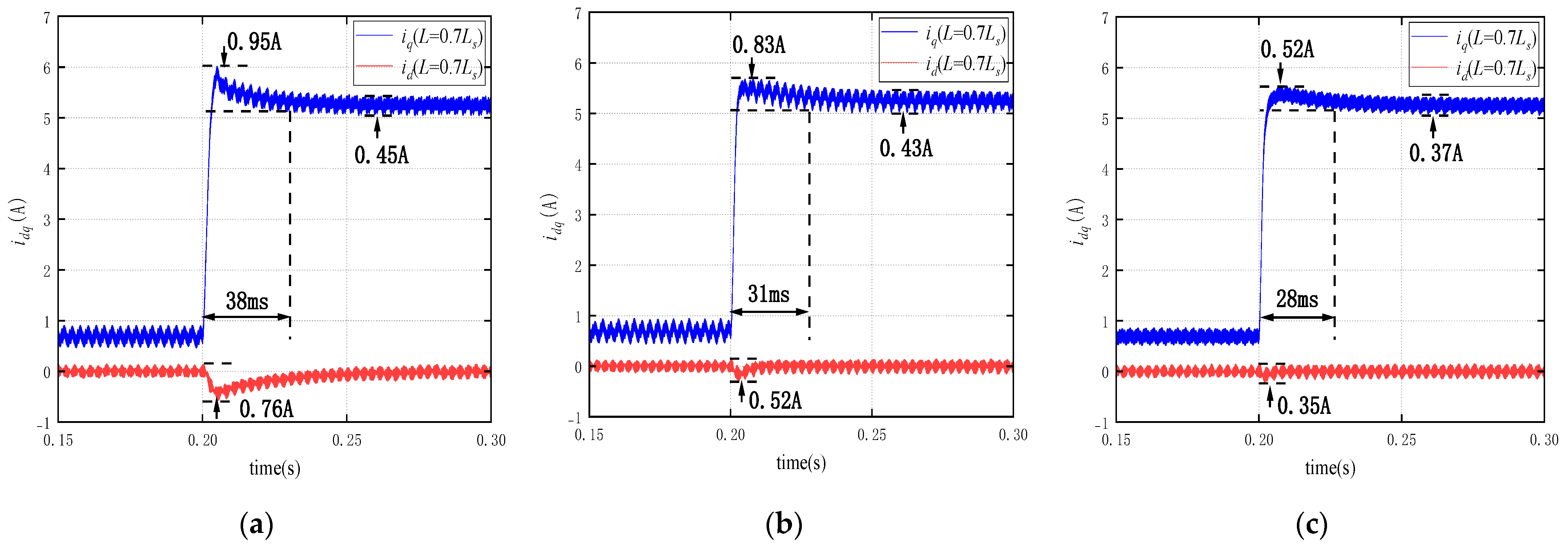
Ls), where the inductance is set to 0.7 times its nominal value. When a 5 N·m load is suddenly applied at 0.2 s, the dq-axis current responses under three decoupling strategies are obtained, as shown in
Figure 5. Under PI linear decoupling (
Figure 5a), the q-axis step change induces a d-axis fluctuation of 0.76 A lasting 38 ms, with a q-axis overshoot of 0.95 A and a steady-state error of 0.45 A. With ESO decoupling (
Figure 5b), the d-axis fluctuation is reduced to 0.52 A for 31 ms, while the q-axis overshoot and steady-state error are 0.83 A and 0.43 A, respectively. In contrast, DOB decoupling (
Figure 5c) achieves the best performance, with only a 0.35 A fluctuation lasting 28 ms, a q-axis overshoot of 0.52 A, and a steady-state error of 0.37 A. These results demonstrate that DOB maintains a shorter settling time and smaller steady-state error even under parameter variations, highlighting its strong robustness and non-periodic disturbance suppression capability.
However, the simulation results above indicate that periodic fluctuations still exist in the dq-axis currents. Consistent with previously reported findings, these fluctuations arise because the disturbance observer has limited bandwidth and cannot effectively capture the medium- and high-frequency components of disturbances. As a result, periodic oscillations persist in the dq-axis currents, including high-order harmonics induced by inverter dead-time effects and stator current harmonics caused by air-gap flux harmonics of the motor. All these factors degrade the performance of DOB, making it necessary to adopt additional current harmonic suppression strategies to further enhance the overall system performance.
3. Design of a Resonance Control Periodic Disturbance Observer
3.1. Improved Disturbance Observer Design Using Resonant Filters
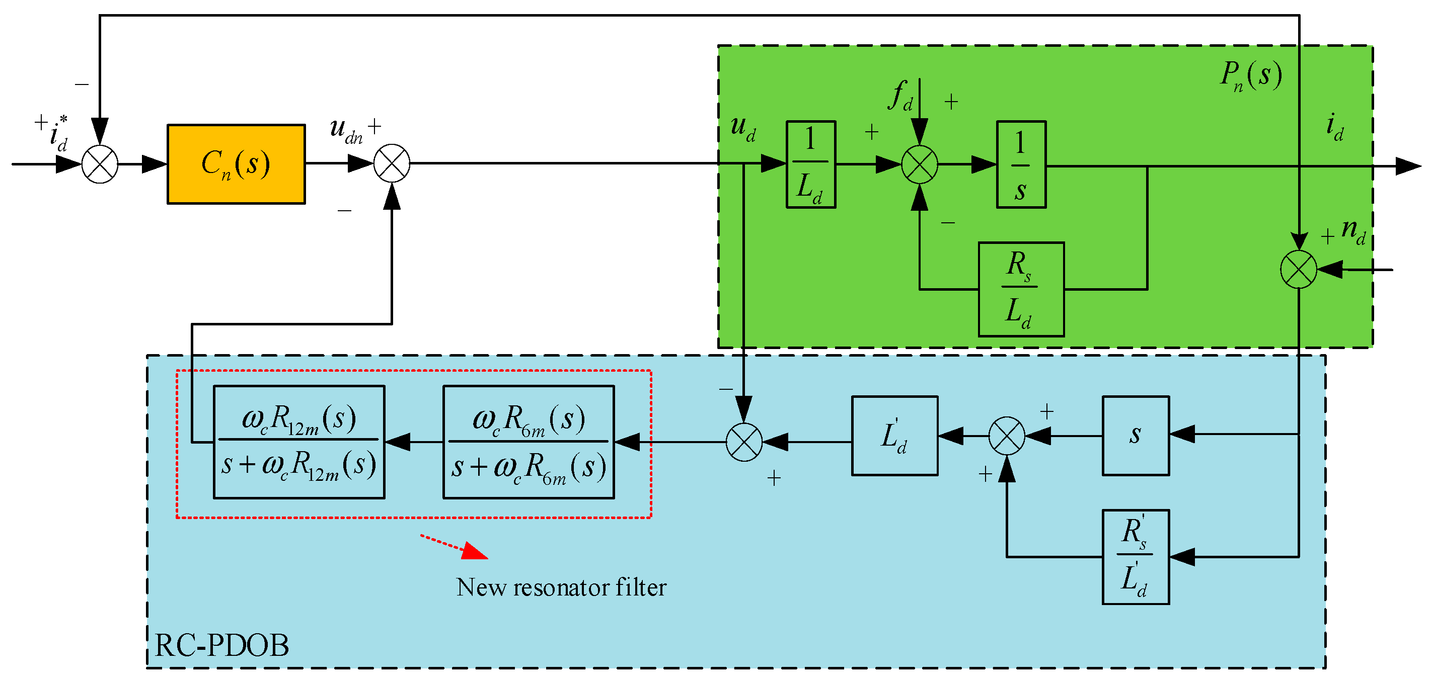
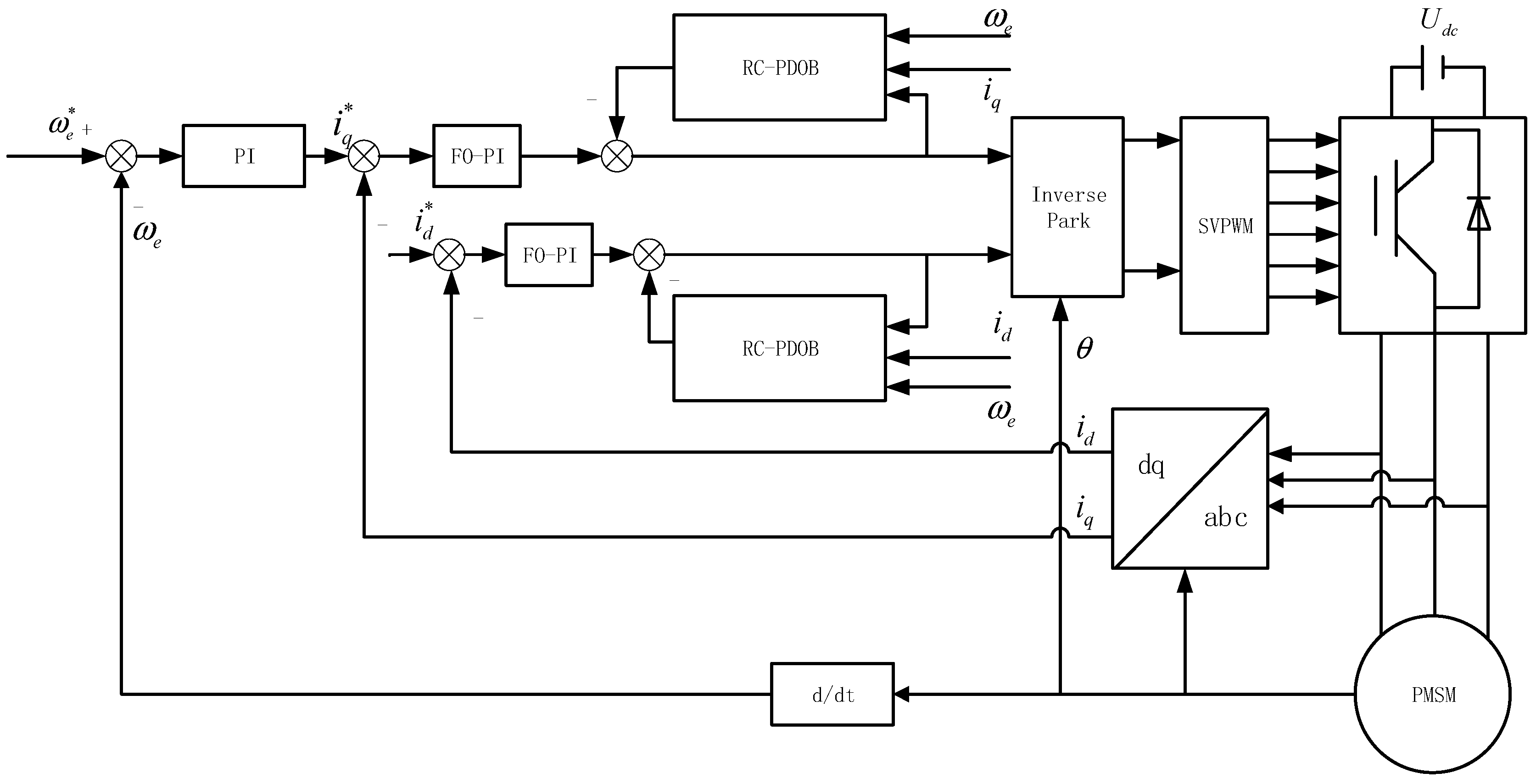
To further suppress current harmonic fluctuations, this paper proposes a Resonant Control Periodic Disturbance Observer (RC-PDOB). Taking the d-axis as an example, the structural block diagram is shown in
Figure 6.
The design of the Resonant Control Periodic Disturbance Observe (RC-PDOB) for the current loop is structurally similar in structure to that shown in
Figure 3. The only modification required is to replace the low-pass filter
Gf(
s) in
Figure 3 with an improved filter that incorporates resonant terms, forming a low-pass resonant filter capable of observing periodic disturbances. Since the higher-order harmonics in the inverter output voltage are negligible, only the 6th and 12th harmonic voltage components are considered in this work. Given that the PMSM current loop is a first-order system, a first-order Butterworth filter is sufficient for the low-pass component.
In control systems, increasing the control bandwidth generally reduces observation error. To effectively track disturbances in the mid-frequency range, the observer bandwidth must be increased. However, expanding the bandwidth also amplifies system noise, which can lead to instability. Therefore, it is necessary to design an observer that selectively detects harmonic frequencies at specific points while remaining unaffected at other frequency bands.
The classical reconstructed resonant term is constructed, whose expression and frequency response characteristics are shown as follows:
where
ω0 represents the fundamental frequency of the system.
kω0 represents the
k-th harmonic of the fundamental frequency
ω0.
To extract the 6th and 12th harmonic components, the reconstructed resonant terms of different orders can be connected in series to form the composite resonant term
R(
s), expressed as:
Let
A = 1,
B = 2, the fundamental frequency
ω0 = 40, the resonant gain coefficient
Kr = 20, and the harmonic order
k = 6 and
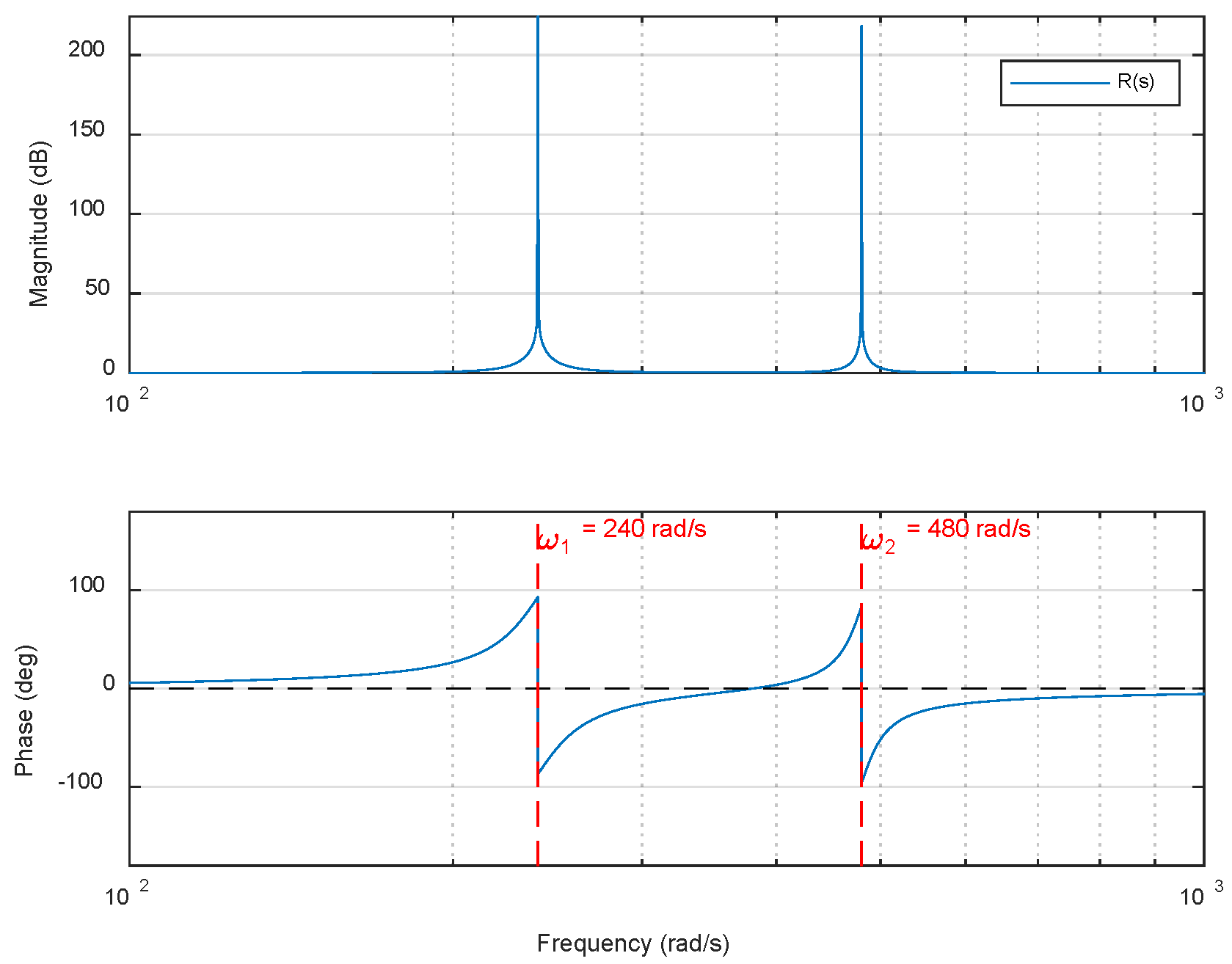
k = 12. The Bode plot of the series reconstructed resonant term is shown in
Figure 7. It can be observed that at the frequencies
ω1 =
6ω0 = 240,
ω2 = 12
ω0 = 480, the magnitude of
Rk(
s) tends to infinity, indicating that the reconstructed resonant term has excellent frequency-selective characteristics.
By incorporating the series resonant term
R(
s) into the low-pass filter
Gf(
s), the resulting expression is given as follows:
The above low-pass resonant filter, incorporating the reconstructed resonant term, closely approximates the ideal filter described. It enables effective observation of periodic disturbance signals at specific frequency points ω = kω0. At other frequency points, the magnitude gain of the resonant term remains 1, allowing the filter to retain its original low-pass characteristics without affecting its fundamental behavior.
In practical engineering applications, in order to maintain high resonant gain while ensuring the stability of the closed-loop system during operation, a quasi-resonant term
Qkm(
s) is often used in place of the standard resonant term
Qk(
s). The expressions for the quasi-resonant term
Qkm(
s) and the reconstructed quasi-resonant term
Rkm(
s) are given as follows:
where
K =
Kr + 1,
K ≫
ωb > 0. The magnitude–frequency characteristics at the resonant frequency are as follows:
By incorporating the reconstructed resonant term shown in Equation (17) into the low-pass filter, the resulting expression of the series reconstructed resonant low-pass filter is obtained, as shown in Equation (19).
The transfer function of the series resonant low-pass filter
Gmf(
s) is given as:
The resonantly enhanced low-pass filter is analyzed in more detail below.
To investigate the influence of the coefficients
K and
ωb on the reconstructed resonant term,
ωb is first fixed while varying the value of
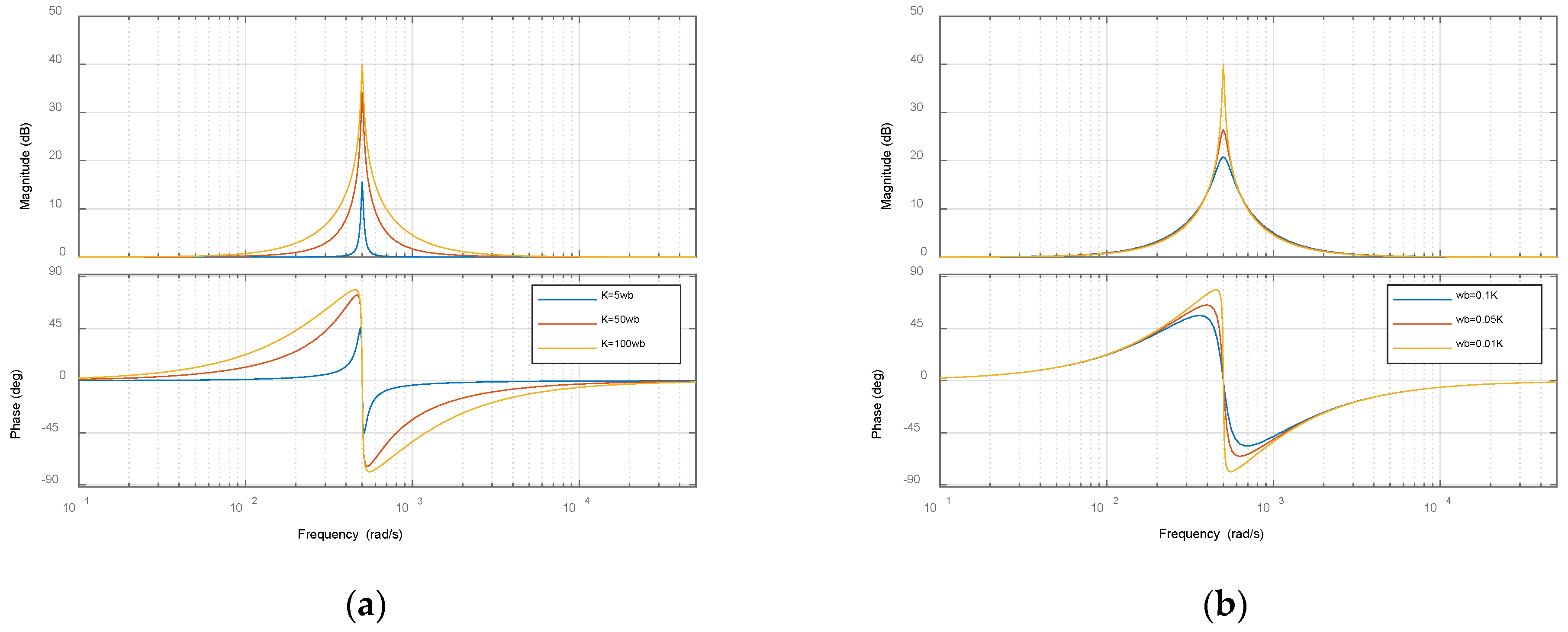
K. The corresponding Bode plots are shown in
Figure 8a. Then,
K is fixed while varying
ωb, and the resulting Bode plots are shown in
Figure 8b. From the plots, it can be observed that when
ωb is fixed, increasing
K leads to a higher magnitude gain at the resonant frequency. However, it also increases the gain in the surrounding frequency range. The phase shift at the resonant point remains approximately the same, while phase variation in other frequency regions is relatively smooth. Conversely, when
K is held constant and
ωb is reduced, the gain at the resonant frequency increases, and the phase shift at the resonant point becomes more abrupt.
The design of the RC-PDOB for the current loop involves three key parameters: the cutoff frequency ωc of the low-pass filter Gmf(s), and the parameters K and ωb of the reconstructed resonant term Rkm(s). The design must comprehensively consider both frequency-domain characteristics and closed-loop stability requirements. System performance objectives are achieved through coordinated tuning of these parameters. The tuning strategy is analyzed as follows:
To avoid instability introduced by the inverse of the nominal plant transfer function, the cutoff frequency
ωc should satisfy
ωc ≤
ωcn, where
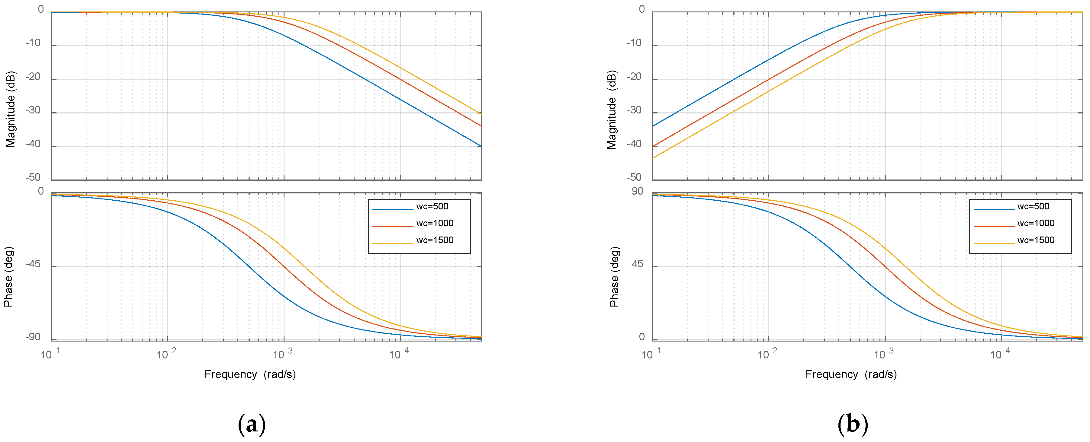
ωcn is the upper limit of the current controller bandwidth. Meanwhile, the phase lag caused by the low-pass filter must be evaluated to ensure system stability. A sufficient phase margin should be reserved to maintain the desired dynamic performance. To investigate the influence of different cutoff frequencies on the system, Bode plots of the low-pass filter function and the sensitivity function are compared for
ωc = 500,
ωc = 1000, and
ωc = 1500, as shown in the
Figure 9.
From the Bode plot analysis, it can be observed that when the electrical parameter is set to ωc = 1000, the filter function Gmf(s) achieves unit gain in the low-frequency range while effectively attenuating high-frequency signals. The magnitude of the sensitivity function 1 − Gmf(s) remains significantly below zero in the low-frequency region, indicating excellent suppression capability against low-frequency disturbances. In addition, the magnitude plots of Gmf(s) and 1 − Gmf(s) exhibit a symmetrical characteristic, further confirming that the designed filter effectively balances the dual objectives of low-frequency disturbance rejection and high-frequency noise attenuation.
- 2.
Matching of Resonant Term Parameters K and ωb.
The parameter K determines the frequency range over which the resonant control is effective, and it directly affects the bandwidth characteristics of Rkm(s). Once K is selected, ωb is used to adjust the resonant peak. A smaller ωb results in a higher resonant gain for the corresponding frequency band, while a larger ωb reduces the gain. This characteristic can be utilized to suppress or enhance the response intensity of specific frequency components.
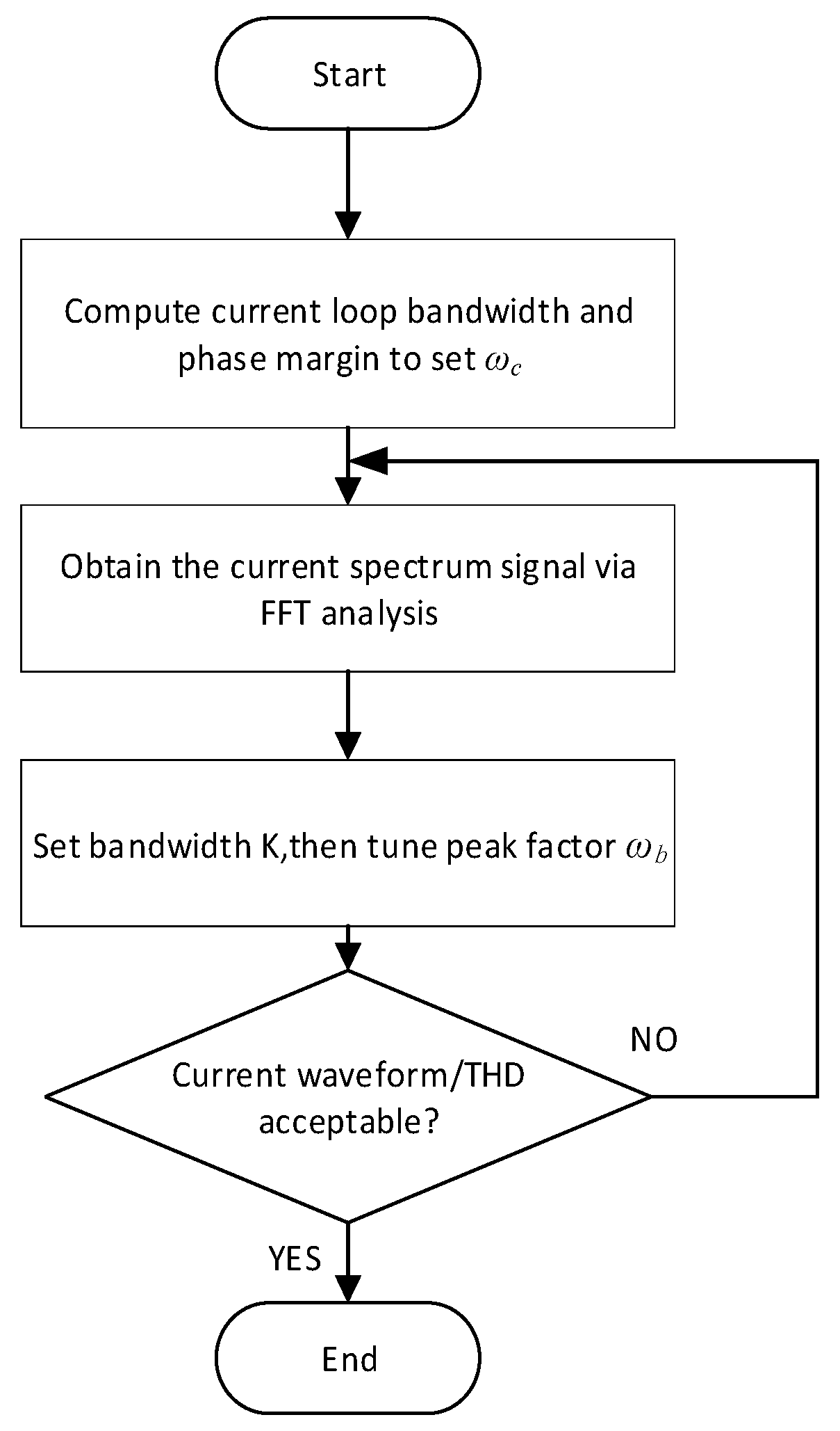
Based on the above analysis, a general tuning procedure for the RC-PDOB can be established. The process is illustrated in
Figure 10.
Based on the above analysis, the disturbance sensitivity function can be expressed as:
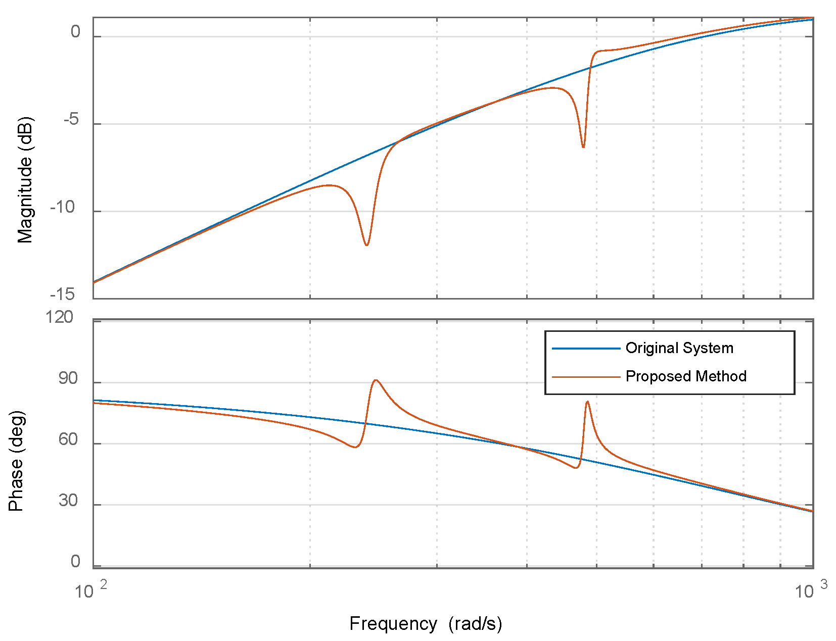
Figure 11 shows the frequency response curves of the decoupling disturbance observer and the resonant-enhanced periodic disturbance observer when the fundamental frequency
ω0 is 40 rad/s, with parameters
ωc = 1000,
K = 10,
ωb = 1. As illustrated in the figure, at six and twelve times the fundamental frequency, the magnitude of the disturbance sensitivity function in the proposed method is significantly reduced compared to the original system, indicating that the total disturbance is effectively suppressed within these frequency bands.
3.2. Stability Analysis of the Resonant Control Periodic Disturbance Observer
For the RC-PDOB control system shown in
Figure 6, the closed-loop transfer function from the reference input to the output, neglecting external disturbances and measurement noise, is given by:
The model error can be expressed in a multiplicative form as:
. Let the zero-pole expressions of the nominal plant model and the filter function be defined as follows:
Substituting Equation (23) into Equation (22) yields:
The characteristic equation of the closed-loop system is then given by:
Then the closed-loop characteristic equation of this system is:
Equation (26) indicates that, in the absence of external disturbances and noise, the stability of the RC-PDOB control system is determined by the pole distribution of the nominal plant model
Pn(
s) and the zero-pole distribution of the filter function
Gmf(
s). In the decoupling control of the PMSM, the nominal model of the controlled plant is inherently stable and can therefore be used directly. The pole part of the filter function
DG(
s) must satisfy stability conditions during the design process; otherwise, the filter will not converge. Therefore, Equation (26) can be further expressed as:
Equation (27) imposes specific requirements on the cutoff frequency and structure of
Gmf(
s). However, due to the unpredictability of the model variation Δ
m(
s), any predetermined cutoff frequency of the DOB may lead to system instability when significant parameter changes occur. Equation (27) can be transformed as:
Then the open-loop gain of the system is
L(
s) = Δ
p(
s)
Gmf(
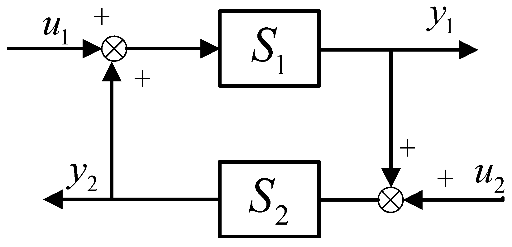
s). Regarding the system shown in
Figure 12:
S1 and
S2 are input-output stable. If condition
γ2(1)γ2(2) < 1 is met(where
γ2(1) and
γ2(2) are the
L2 norms of
S1 and
S2, respectively), then this system is also input-output stable. The proof is as follows:
where
e1 =
u1 +
S2(
y1 +
y2), and follows:
If the condition is satisfied:
The system is asymptotically stable.
According to the small gain theorem,
S1 = Δ
p(
s),
S2 =
Gmf(
s), the robustness condition of the system, ensuring bounded input-output behavior, is given by:
The designed filter function can ensure the stability of the RC-PDOB system as long as it satisfies the condition specified in Equation (34).
5. Conclusions
This paper proposes a current decoupling and harmonic suppression strategy for a permanent magnet synchronous motor (PMSM), based on a resonant control periodic disturbance observer (RC-PDOB). The method effectively decouples the dq-axis current loop and suppresses the 6th and 12th current harmonics present. Through theoretical analysis and experimental validation, the following conclusions are drawn:
Significant Improvement in Current Decoupling Capability: The dq-axis decoupling model based on the disturbance observer (DOB) can effectively eliminate the cross-coupling terms in the current loop. When the q-axis current changes, compared with the traditional linear feedback decoupling method, the DOB decoupling estimates the coupling terms as the total disturbance and eliminates their influence through a feedforward compensation method, resulting in the duration of d-axis current fluctuations being shortened from 34 ms to 26 ms, and reducing the q-axis steady-state error from 0.32 A to 0.28 A, thereby improving the dynamic performance and steady-state performance of the system. In the case of changes in inductance parameters, when using the DOB method, the duration of d-axis current fluctuations is 28 ms, and the q-axis steady-state error is 0.37 A. In terms of dynamic and steady-state performance, it is superior to the traditional method, effectively reducing the non-periodic interference caused by electrical parameter changes. This enhances the parameter robustness of the system and provides a more excellent dynamic response in situations such as sudden load changes and parameter mismatches.
Outstanding Harmonic Suppression Capability: The proposed RC-PDOB achieves targeted observation and compensation of specific frequency disturbances (6th and 12th harmonics) by embedding a proportional-resonant controller into the filtering stage of the disturbance observer and incorporating a series resonant structure. This enables coordinated suppression of higher-order current harmonics, significantly enhancing the system′s harmonic rejection performance.
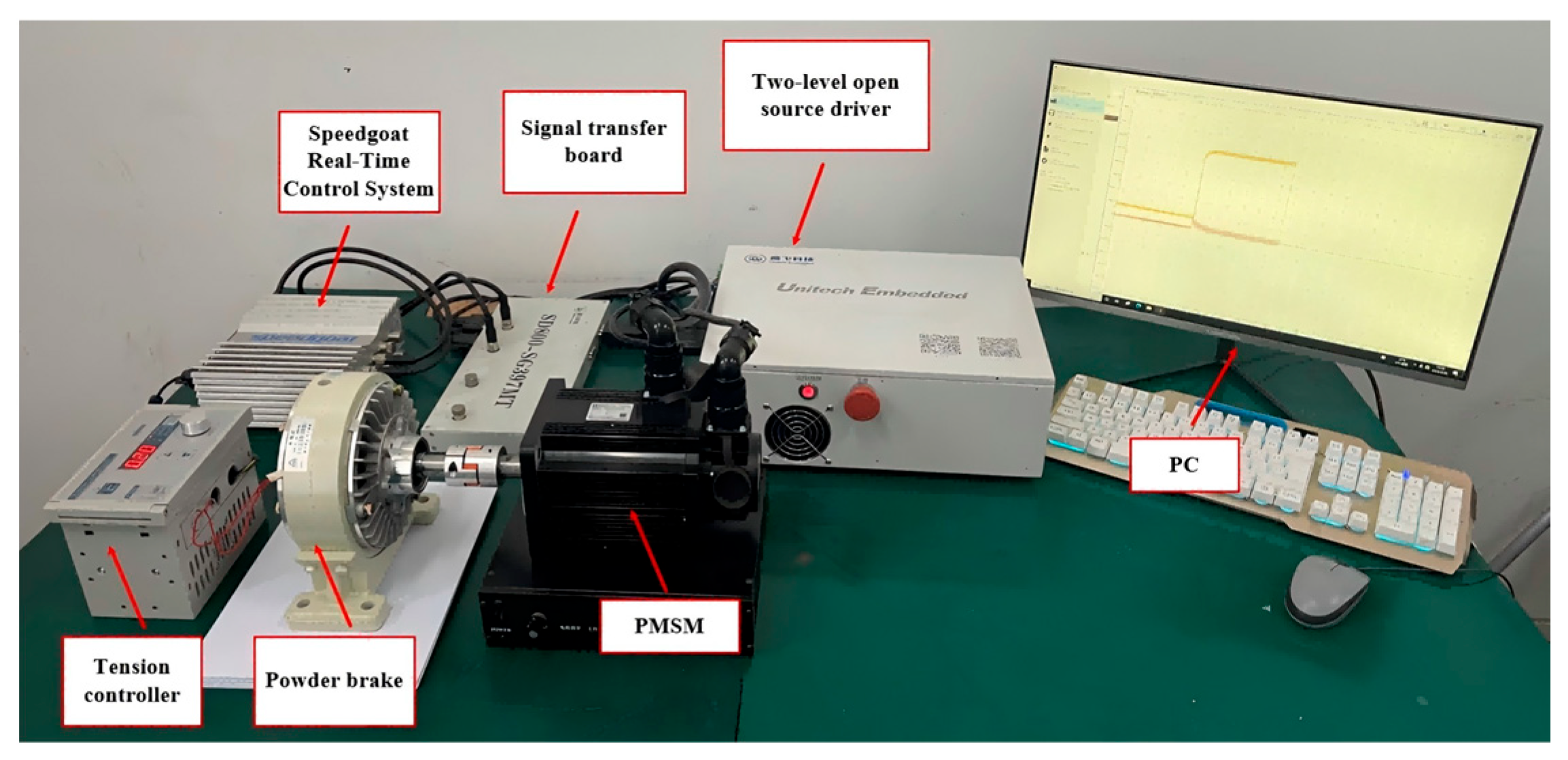
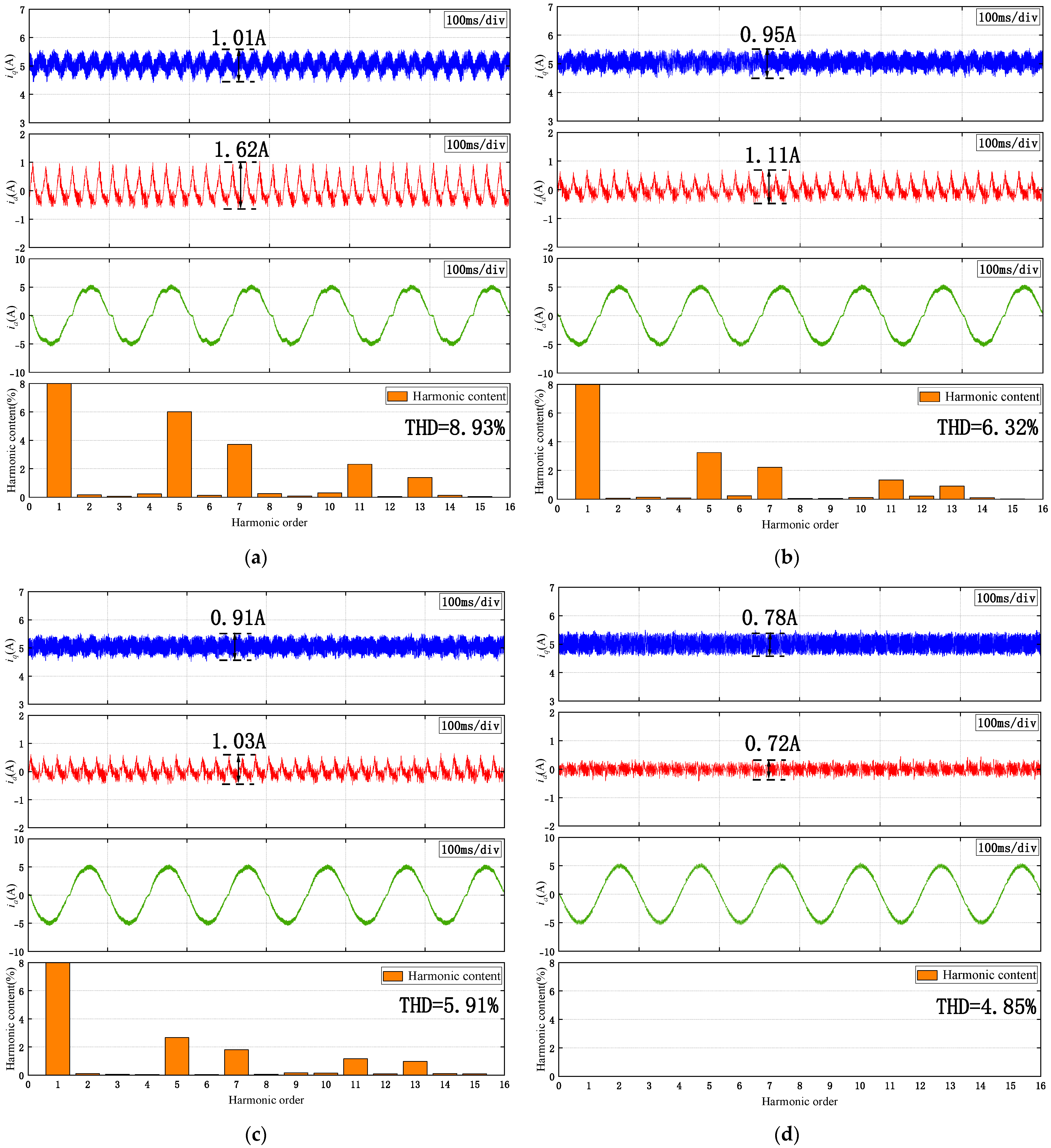
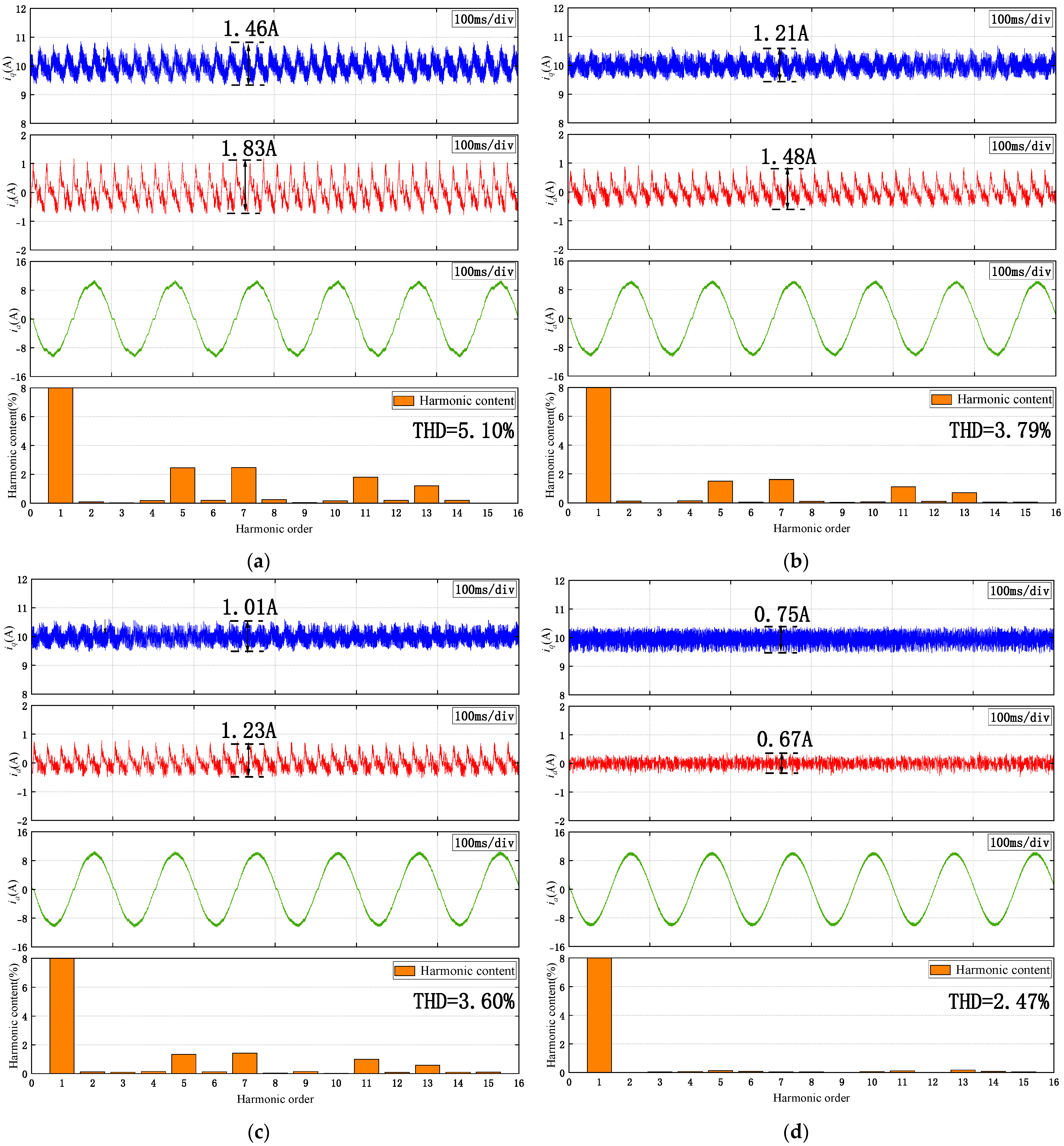
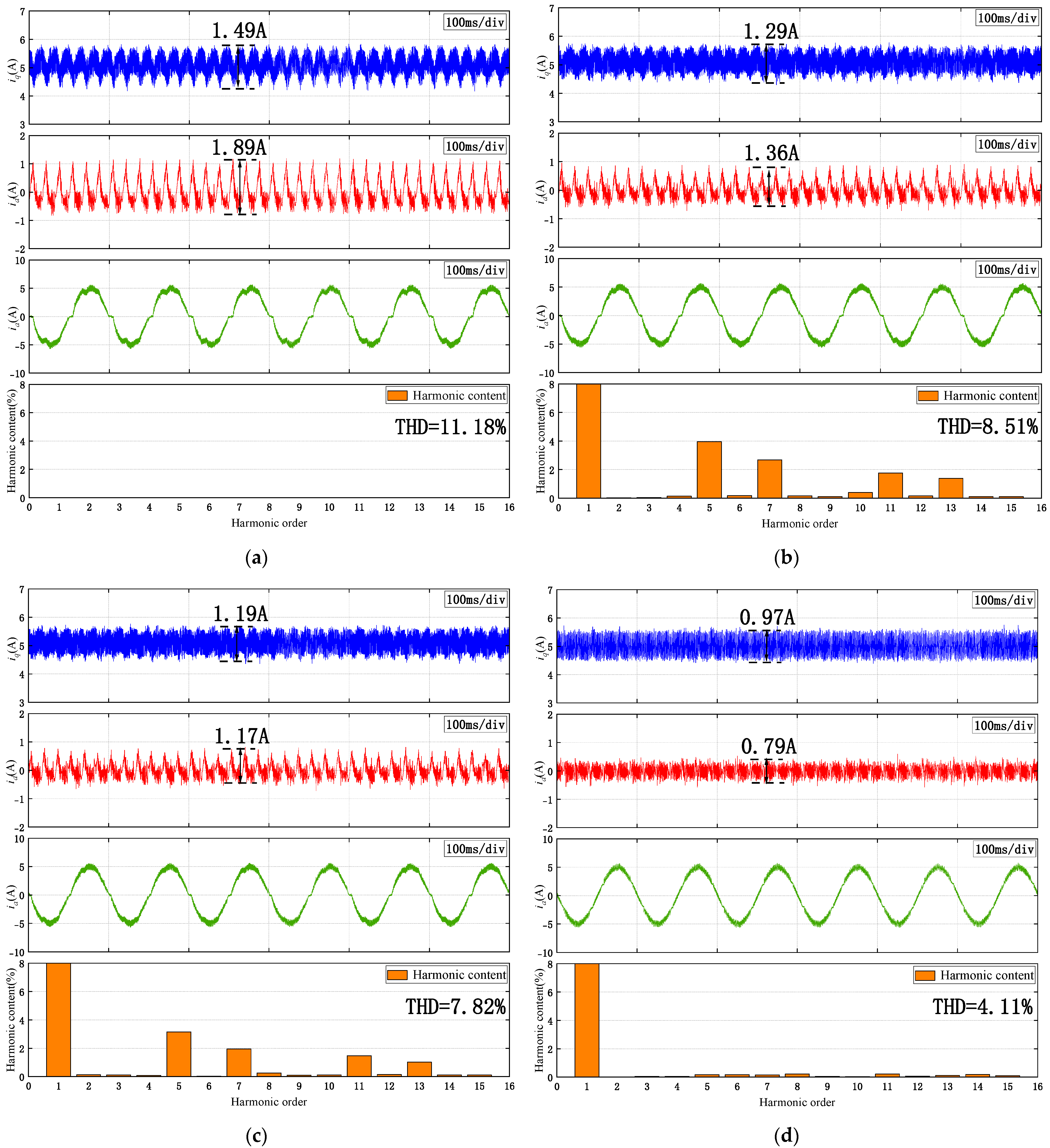
The excellent control performance was verified through experiments: The steady-state and dynamic experiments conducted on the Speedgoat hardware-in-the-loop (HIL) simulation platform demonstrated that the performance of the RC-PDOB controller was superior to the FO-PI, FO-ADRC, and FO-DOB control strategies. Specifically, at a constant load of 5 N.m and a constant speed of 150 r/min, it reduced the 5th, 7th, 11th, and 13th harmonic components to 0.32%, 0.27%, 0.21%, and 0.14% respectively. It achieved the lowest total harmonic distortion (THD) in the steady-state current, reducing it from 8.93% to 4.85%. The effectiveness of the proposed method was also demonstrated during operation at the rated load. Moreover, in the case of parameter variations, the RC-PDOB still maintained good steady-state results, indicating its good parameter robustness. Finally, under load variations, it exhibited a faster response time and smaller speed fluctuations. These results highlight the strong applicability of this controller in engineering applications and its significant potential in practical applications.
