Article

Mechanical Characterization and Azithromycin Coating of Melt Electrowritten Polycaprolactone Mesh Implants for Prolapse Repair

by
Joana Pinheiro Martins
1,
Ana Sofia Sousa
2,
Sofia Costa de Oliveira
3,
António Augusto Fernandes
1,2 and
Elisabete Silva
1,*
1
Associate Laboratory of Energy, Transports and Aerospace, Institute of Science and Innovation in Mechanical and Industrial Engineering, 4200-465 Porto, Portugal
2
Faculty of Engineering, University of Porto, 4200-465 Porto, Portugal
3
Rede de Investigação em Saude (RISE)-Health, Department of Pathology, Faculty of Medicine, University of Porto, 4200-319 Porto, Portugal
*
Author to whom correspondence should be addressed.
Appl. Sci. 2025, 15(17), 9436; https://doi.org/10.3390/app15179436
Submission received: 4 July 2025 / Revised: 20 August 2025 / Accepted: 23 August 2025 / Published: 28 August 2025

Abstract

Pelvic organ prolapse (POP) cases have been rising, affecting women’s quality of life. Severe cases often require surgical mesh implants, which can cause complications like tissue erosion and infection, leading the FDA to ban transvaginal meshes for POP. To address this, polycaprolactone (PCL) mesh implants, produced via melt electrowriting (MEW), were evaluated mechanically and coated with azithromycin, an antibiotic for genitourinary infections. Uniaxial tensile and cyclic tests assessed the long-term behavior of the meshes over 100 cycles. The results show that while all PCL meshes had similar behavior, those with 1 mm pores sustained higher stress, whereas 1.5 mm pore size meshes had mechanical properties closer to vaginal tissue but remained stiffer. Cyclic tests revealed initial damage and hardening during plastic deformation, with tensile tests confirming increased stiffness, as Young’s modulus rose between 19.2% and 29.3%. Zone inhibition and biofilm assays evaluated azithromycin’s effectiveness against bacterial infection. Even though FTIR analysis could not confirm antibiotic incorporation, the drug coated meshes show inhibitory activity against E. coli biofilm formation and MSSA in its planktonic state. Scanning Electron Microscopy supported these findings. These results suggest that MEW-fabricated PCL meshes coated with azithromycin hold promise as improved implants for POP treatment.

1. Introduction

Pelvic organ prolapse (POP) is one of the most common pelvic floor dysfunctions (PFDs) characterized by the descent of pelvic organs through the vaginal walls and pelvic floor due to weakened or damaged ligaments, connective tissues, or muscles [1]. POP can be caused by different factors, such as age and mass index, the most common being pregnancy. Depending on the anatomical region or organ that is affected, there are different types of POP: in the case of cystocele (anterior vaginal wall prolapse), there is a bladder prolapse; in enterocele and urethrocele, there is a small-intestine and urethra prolapse into the vagina, respectively; in rectocele (posterior vaginal wall prolapse), there is a prolapse of the rectum, and in vaginal vault prolapse, the top part of the vagina falls into the vaginal canal [2].
Management strategies for POP depend on the patient’s individual characteristics and the severity of the condition, encompassing both non-surgical and surgical approaches. Non-surgical options include pelvic floor physical therapy, hormonal therapy, weight loss and vaginal pessaries [3]. When these are not enough to treat the prolapse, or it is too severe, doctors will suggest performing surgery, which can be of two types: obliterative and reconstructive. The former has a high success rate, while the latter has a re-operation rate of 30% since the surgery does not repair the underlying weakened tissues, leading to recurrent prolapse [4,5,6]. The surgeries using native tissues to restore the prolapsed organs are also an option, but they still present a high failure rate of 29% [7]. Another option for POP treatment is synthetic surgical meshes, which can be classified based on density, structure, mechanical properties, porosity, filament type, and absorption capacity as these factors can influence cell attachment and tissue regeneration [8]. The materials used to produce the meshes can be non-absorbable (e.g., polypropylene (PP), polyethylene terephthalate (PET)), absorbable (e.g., polycaprolactone (PCL), polylactic acid (PLA), polyurethane (PU)) and a combination of both. The former produce meshes that maintain their mechanical properties but are stiffer, which causes the weakening of the surrounding tissues due to stress shielding, and can cause infection after the implantation, while the absorbable meshes degrade during the healing process, leading to the loss of tensile strength once absorbed [9,10]. Transvaginal prolapse repair meshes were classified as high-risk products in 2016. Subsequently, in 2019, their production and distribution were banned by the FDA, on the basis that the potential harms exceed the potential advantages. Reported complications, often necessitating additional surgery for mesh removal [11], are mainly attributed to limited biocompatibility and inadequate biomechanical features of the meshes [12]. An ideal mesh should be biocompatible, nontoxic, and have antibacterial properties and appropriate mechanical properties. The design should provide support without creating excessive strength, and the shape and size of the mesh should be specific to the patient [13]. Also, although relatively rare, mesh-related infections are serious complications that can arise after pelvic floor repair, occurring in up to 8% of cases and can hinder proper integration into host tissues, sometimes resulting in mesh exposure [14]. The research indicates that 77% of vaginal meshes removed contained pathogenic bacteria [14,15]. Mesh infection can result from contamination of the implant itself or occur during the surgical procedure. Variations in the composition and diversity of the vaginal microbiota may increase individual susceptibility to pelvic mesh infections following implantation. Azithromycin (Az), an antibiotic with broad-spectrum activity, is frequently used in the treatment of pelvic infections and UTIs [16]. It has shown antimicrobial efficacy against bacteria associated with surgical mesh infections, particularly when employed as a coating on implants [17].
Electrospinning (ES) is a fiber fabrication procedure that utilizes an electric field between a spinneret and a collector to produce continuous polymer fibers from a solution or melt, enabling the generation of ultra-fine, nanoscale fibers. However, given the influence of the electrical field on the polymer solution, it is not possible to have a controlled deposition of fibers [18,19]. By combining electrospinning and additive manufacturing technologies, melt electrospinning writing (MEW) emerged, enabling the printing of intricate 3D architectures with high precision and reduced costs using melted polymers. This relatively recent technique has mostly been studied for tissue engineering and biomedical applications. MEW makes it possible to build structures with mechanical strength at micrometer and nanometer diameter range without solvents, avoiding toxicity, biodegradability, and biocompatibility issues. Moreover, it facilitates the replication of native tissue properties while supporting cell attachment, growth, and proliferation [12]. In the POP context particularly, MEW has already been studied as a method of producing biocompatible and biodegradable meshes [20,21,22]. Cunha et al. printed PCL mesh implants with different filament diameters and layers. The mechanical properties of these printed filaments were compared to those of the PP Restorelle® mesh and vaginal tissue. Their findings indicated that the PCL-printed meshes exhibited biomechanical properties more closely resembling vaginal tissue than the Restorelle® mesh [20,23]. Furthermore, the effectiveness of producing MEW implants incorporating antimicrobial agents has been demonstrated, offering a promising strategy to enhance the resistance of implants against infection [24].
This study aims to develop PCL mesh implants with reduced stiffness compared to conventional synthetic meshes, exhibiting mechanical properties similar to vaginal tissue. Additionally, the incorporation of antibiotics aims to prevent complications commonly associated with pelvic meshes that often lead to implant removal.

2. Materials and Methods

The objective of this study is to create biodegradable square-shaped mesh implants in response to the issues associated with synthetic meshes and mesh-related complications, which have recently been banned from the market. Figure 1 presents a schematic flowchart of this study, regarding printing and the mechanical characterization of meshes for POP treatment.

2.1. Biodegradable PCL Mesh Implants Production

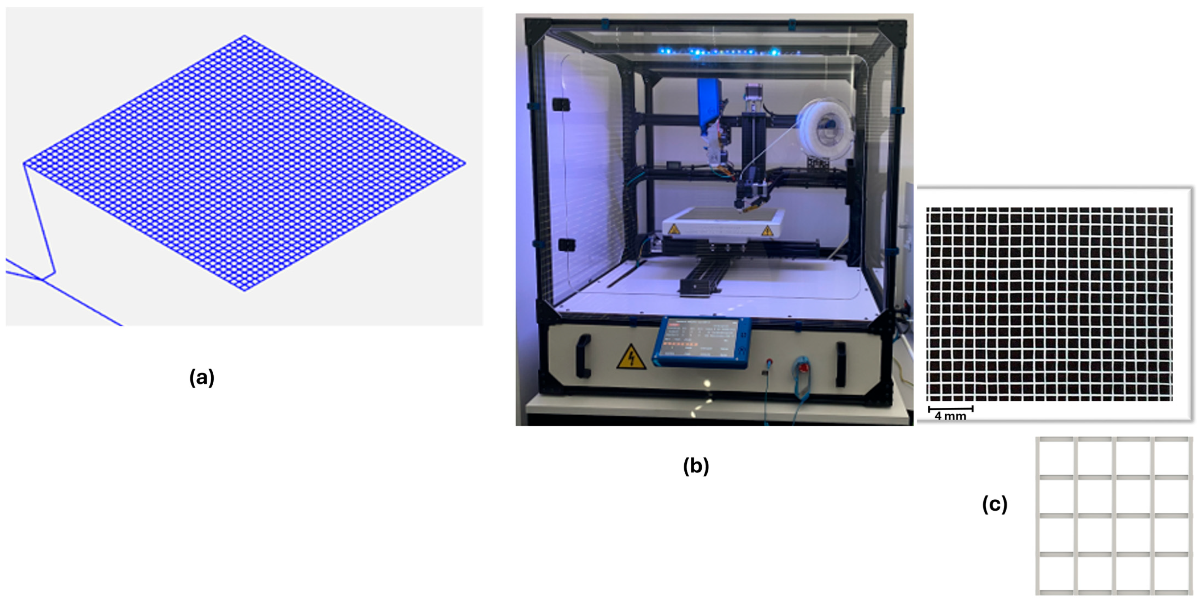
To print the square-shaped mesh implants through MEW, technical-grade PCL with a density of 1.1 g/cm3 (ISO 1183 [25]) was used. This material, obtained as a commercial product named Facilan™PCL 100 (3D4Makers, Haarlem, The Netherlands), was provided in the form of a 1.75 mm diameter filament. This material is advantageous for MEW due to its low melting temperature and fast solidification [26]. The PCL meshes were printed with a MEW machine (Figure 2b). The square-shaped mesh implants (Figure 2a,c) were designed using the FullControl G-code Designer software (version 3) [23].
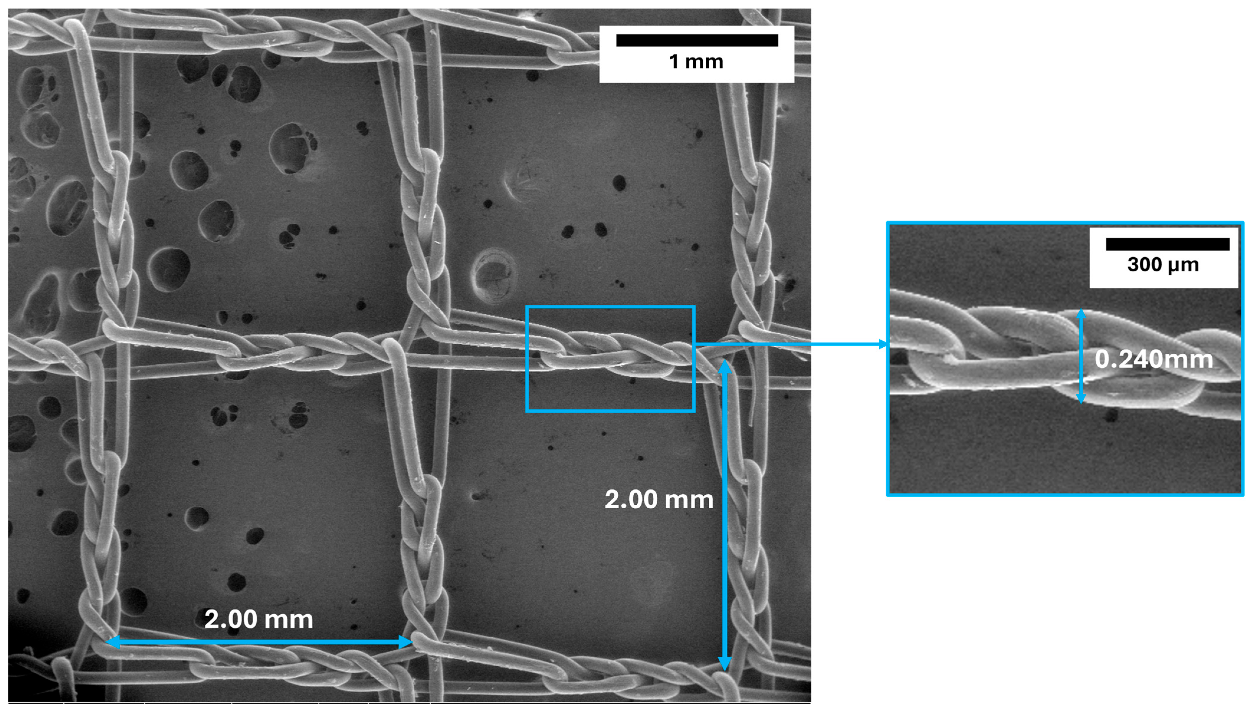
The characteristics of the meshes were introduced in the software, specifically square-shaped geometry with 240 µm fiber diameter of two different pore sizes, 1 and 1.5 mm (240_Q1.0 and 240_Q1.5), allowing the printing of 84 × 84 mm meshes. The diameter selected for the meshes was based on the literature and is associated with the fact that the Restorelle® mesh features three filaments of 80 µm that culminate in 240 µm [12,22]. That way the produced meshes will have a similar thickness to the Restorelle® ones (Figure 3). After calibrating the printing parameters, the values in Table 1 are the ones that allowed printing a stable continuous filament, without elongation.
The extrusion rate of the polymer applied to the G-code was obtained through Equation (1). E is the extrusion rate, Dfiber the diameter of the intended fiber (240 µm), lfiber is the length of the printed fiber (84 mm), and Dfilament is the filament diameter (1.75 mm).
E = D F i b e r 2 × l f i b e r D F i l a m e n t 2

2.2. Mechanical Tests

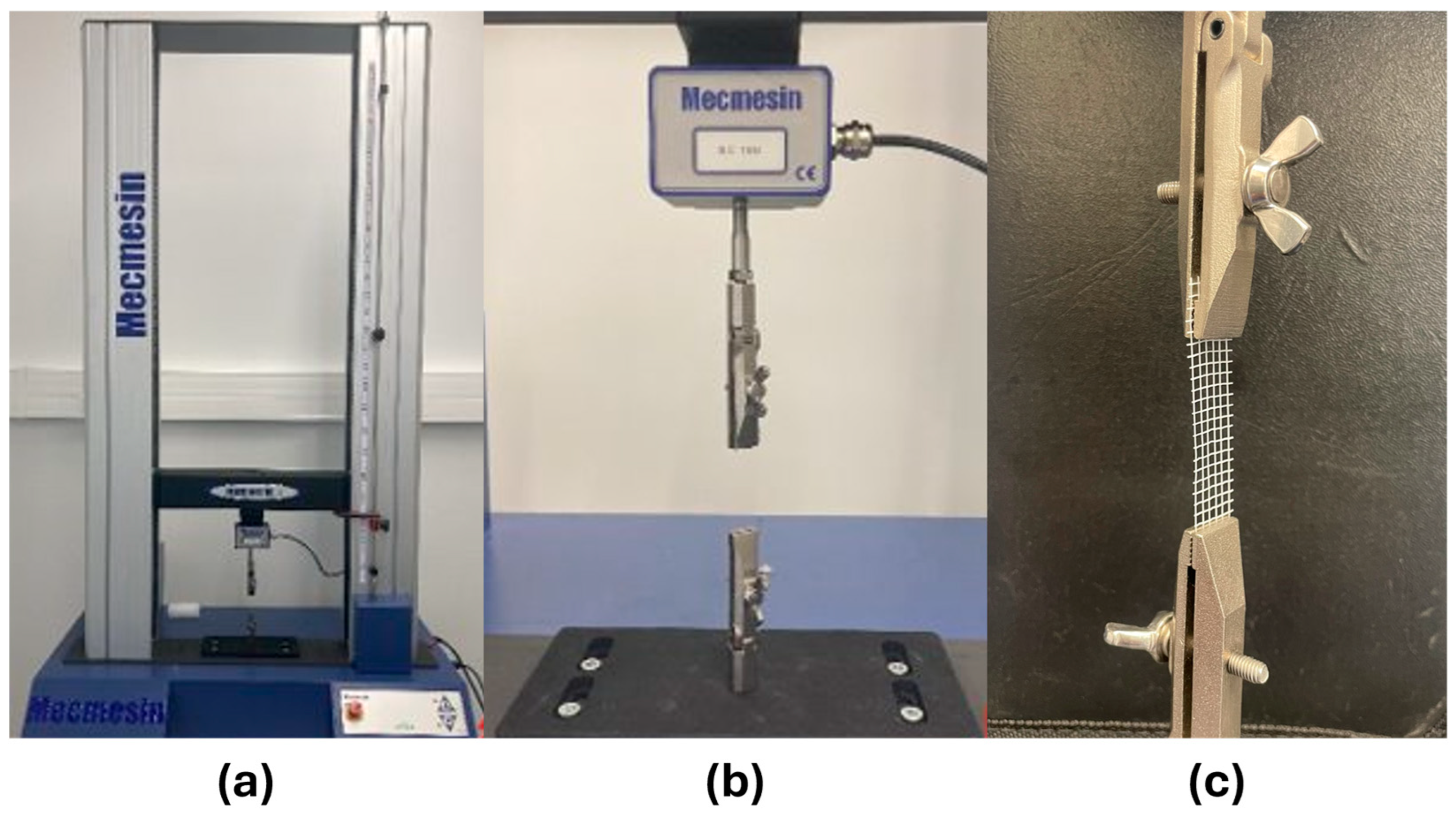
Uniaxial tensile and cyclic tests on the printed meshes were conducted using a Mecmesin Multitest 10-i system (Mecmesin GmbH, Freiburg, Germany) and the EmperorForce Testing System software (version 1.17). The equipment was fitted with a 500 N load cell, and the experiments were conducted at a crosshead speed of 10 mm/min (Figure 4). Samples measuring 50 × 10 mm were tested, and force–displacement curves were acquired for three specimens per group. These were used to calculate average stress–strain curves, with strain and stress obtained using Equations (2) and (3), respectively. Nominal stress was considered apparent, as the cross-sectional area was estimated by multiplying the filament diameter (given that the meshes consisted of a single layer) by the sample width (10 mm).
σ = F A
σ: stress (MPa).
F: applied force (N).
A: cross-sectional area (mm2).
ε = L L 0
ε: strain.
ΔL: displacement (mm).
L0: initial gauge length (mm).
From the stress–strain curve, the Young’s modulus E (elastic modulus) can be determined as the slope of the linear region, calculated as the ratio of stress to strain (Equation (4)). This modulus represents the stiffness of the material and quantifies its resistance to elastic deformation under mechanical loading.
E = σ ε
After the tensile tests, cyclic tests were performed to evaluate the behavior of the meshes when subjected to cyclic loading conditions. The samples were continuously compressed and distended for 100 cycles [27]. The maximum load applied was an 80% load that caused sample rupture in the uniaxial tensile tests, as described in previous studies [28]. After the cyclic tests, the samples were stored and subjected to uniaxial tensile testing to evaluate their performance after cyclic loading conditions and how these altered the stress–strain curves obtained previously.

2.3. Preparation of Azithromycin-Loaded PCL Meshes

The antimicrobial incorporation was achieved through azithromycin coating of the meshes [24]. To ensure sterility, samples and materials were exposed to UV-C light for 30 min inside a Class II biological safety cabinet (Thermo Scientific MSC-Advantage, Thermo Fisher Scientific, Waltham, MA, USA). Two azithromycin solutions (Sigma-Aldrich, Burlington, MA, USA) were prepared in pure ethanol: one containing 0.1% (w/v) Az and the other 0.15% (w/v) Az.
Meshes were immersed in the respective solutions for 24 h, followed by rinsing in pure ethanol to remove excess antibiotic and eliminate potential solvent interference. Samples were then air-dried in the cabinet for an additional 24 h.

2.4. FTIR Spectral Analysis of PCL Meshes Before and After UV-C Sterilization

FTIR (Fourier Transform Infrared) spectra were acquired using a Cary 360 spectrometer (Agilent Technologies, Santa Clara, CA, USA) with a diamond ATR (attenuated total reflectance) accessory. FTIR spectra were obtained for PCL meshes before and after UV-C light sterilization, as well as for Az-loaded PCL meshes (PCL-Az), to assess possible structural changes and confirm azithromycin incorporation. Six groups were analyzed: unsterilized PCL, sterilized PCL, PCL treated with ethanol (control), and PCL treated with Az at 0.1% and 0.15%. Spectra were collected in the 750–4000 cm−1 range with a resolution of 4 cm−1.

2.5. In Vitro Assessment of Microbial Growth

Three bacterial strains were used to test the antimicrobial properties of the meshes: methicillin-susceptible Staphylococcus aureus (MSSA, ATCC 29213), methicillin-resistant Staphylococcus aureus (MRSA, ATCC 43300), and Escherichia coli (E. coli, ATCC 25922). All strains were obtained from the American Type Culture Collection (ATCC, Manassas, VA, USA) and cultured in Brain Heart Infusion (BHI) broth.

2.5.1. Agar Diffusion Assay for Antibacterial Activity

The agar diffusion assay was performed to evaluate the antibacterial activity of the meshes. A bacterial suspension was spread in triplicate onto Mueller–Hinton agar plates, and 1 cm2 mesh samples were placed on the surface. Prior to incubation at 37 °C for 24 h, the samples were sterilized by exposing both sides to UV-C light for 30 min. The diameters of the inhibition zones were measured after 24 and 48 h to assess the antibacterial performance of the azithromycin-coated meshes. PCL meshes without azithromycin served as the control.

2.5.2. Assessment of Biofilm Formation on Coated Meshes

A 1:10 dilution of the bacterial suspension was prepared in BHI medium, and 1 mL was added to each well of a 12-well plate containing the mesh samples. Plates were incubated at 37 °C for 24 h under static conditions. To assess the impact of azithromycin incorporation, biofilm metabolic activity was evaluated using the XTT (tetrazolium salt) assay and biomass formation was evaluated through crystal violet (CV) assays.
During the XTT assay, the supernatant was discarded, and the samples were rinsed three times with (PBS) phosphate-buffered saline. Then, 2 mL of tetrazolium salt solution was added to each well, followed by incubation for 3 h in the dark with agitation. The optical density (OD) of the surrounding solution was measured at 492 nm using a spectrophotometer (SHIMADZU UV-160A (SHIMADZU, Kyoto, Japan)), in triplicate. Unloaded PCL meshes served as the negative control.
For the CV assay, samples were washed three times with PBS and treated with 0.5 mL of methanol per well. After 30 min of incubation, the methanol was removed and allowed to evaporate at room temperature for another 30 min. Then, 1 mL of 0.5% CV solution was added and incubated for 20 min. Following staining, samples were rinsed in triplicate with water. Subsequently, each well received 1.5 mL of 33% (v/v) acetic acid, which was allowed to react for 15 min. The optical density was then determined three times at 590 nm, with the control group serving as a reference.

2.6. SEM Analysis of Mesh Morphology and Bacterial Colonization

Scanning Electron Microscopy (SEM) was employed to evaluate the surface morphology of the coated meshes and to assess the presence of bacterial colonization. Analyses were conducted using a high-resolution (Schottky) environmental SEM equipped with X-ray microanalysis and Electron Backscattered Diffraction (EBSD) capabilities (FEI Quanta 400 FEG ESEM (FEI Company, Hillsboro, OR, USA)/EDAX Genesis X4M (Gatan Inc., Pleasanton, CA, USA). Prior to imaging, samples were coated with a thin Au/Pd film using the SPI Module Sputter Coater (Structure Probe, Inc., West Chester, PA, USA).

3. Results

3.1. Uniaxial Tensile Tests

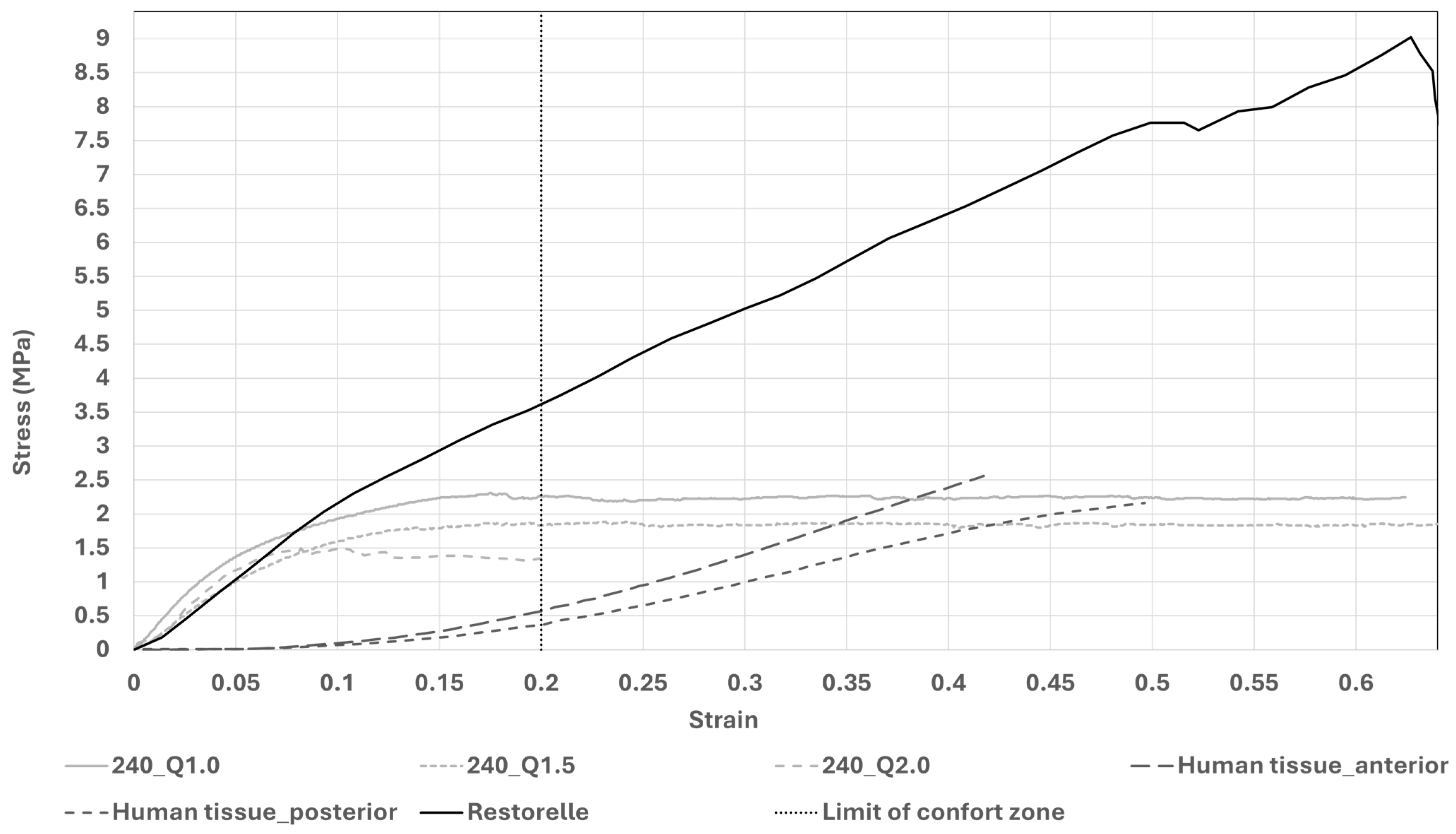
The acquired load–displacement data were used to generate mean stress–strain curves, shown in Figure 5. These curves include data for a 240 µm diameter mesh featuring 2.0 mm pores (240_Q2.0), obtained from previous work [21]; the stress–strain curve of the commercial Restorelle® mesh [20]; and curves derived from human vaginal tissue affected by anterior and posterior prolapse [28,29]. The graph also highlights the “comfort zone,” which refers to the typical stress levels experienced during daily activities, generally corresponding to strains of up to 20% [30].
Although the meshes exhibit similar mechanical behavior, they differ in the maximum stress values achieved, as shown in Table 2. This table also includes the maximum stress values for prolapsed human vaginal tissue and the commercial Restorelle® mesh, as well as the stresses measured within the comfort zone.

3.2. Cyclic Tests

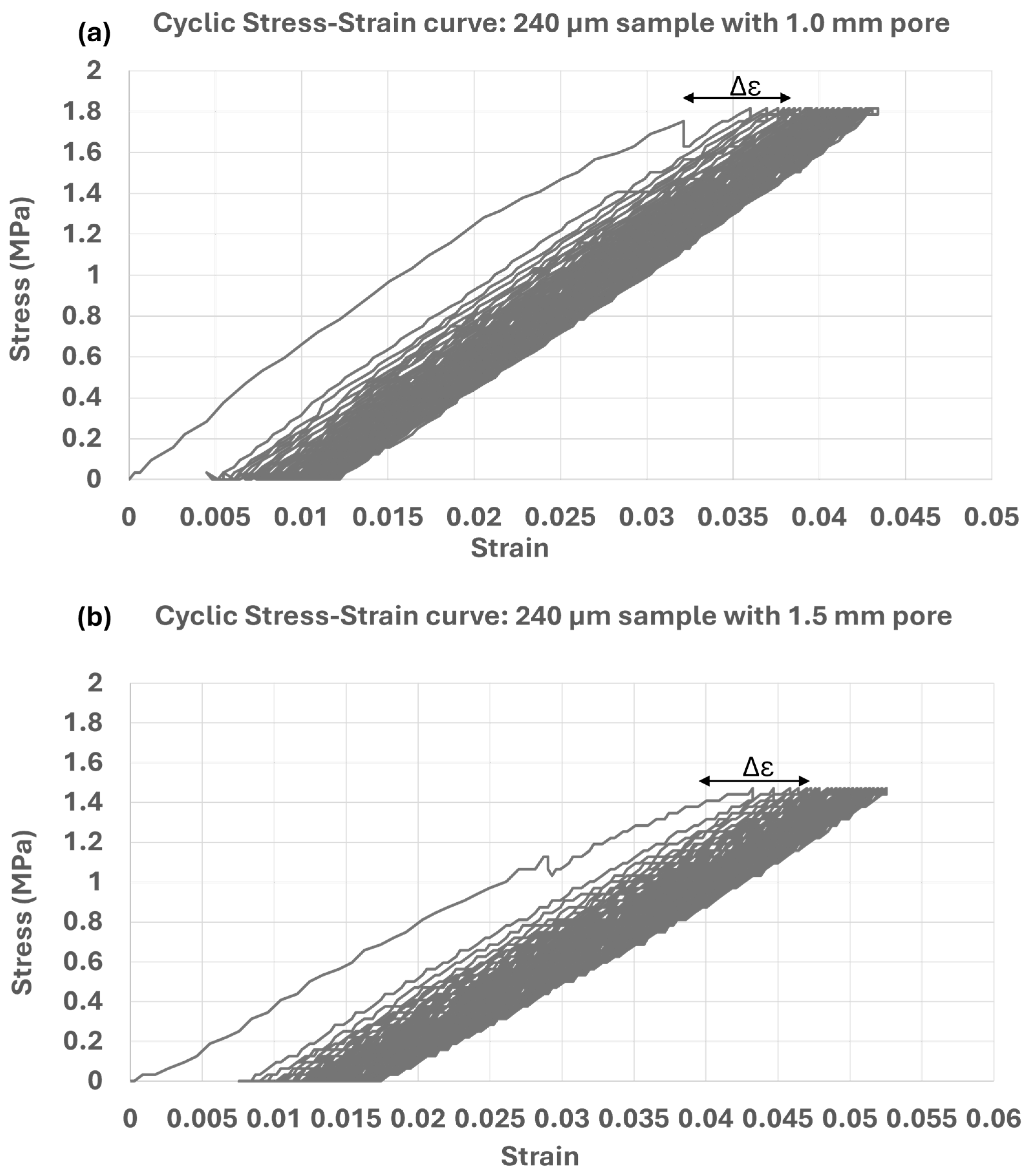
The cyclic tests were performed to evaluate the performance of the meshes to repeated loads, mimicking the expected in vivo loads. Figure 6 depicts the results of one sample representative of each tested group, namely a 240 μm filament, and pore sizes of 1 and 1.5 mm. The graphs show that the samples withstand the loads they are subjected to for 100 cycles without significant failure. The strain variation (Δε) in the sample is determined by calculating the difference between the strain at the maximum stress in the 100th cycle and that in the 1st cycle. Table 3 summarizes the average strain variation for each mesh type.
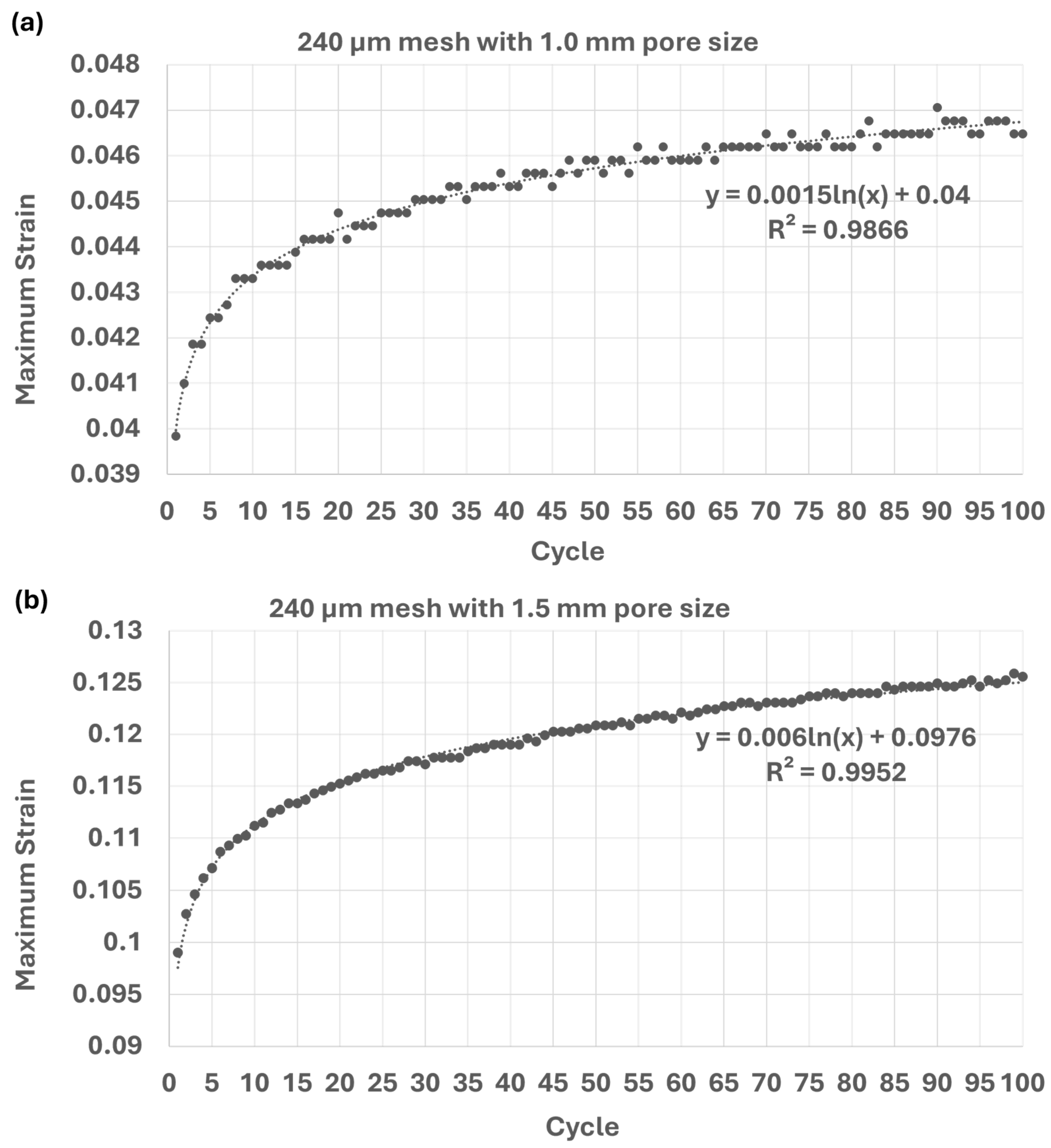
Figure 7 presents the evolution of maximum strain over the 100 loading cycles for two mesh configurations: both with 240 µm fiber diameter but differing in pore size (1.0 mm and 1.5 mm). The plotted values represent the strain recorded at the point of maximum applied stress in each cycle. This analysis provides an insight into the cumulative deformation behavior of the meshes under repeated loading. A logarithmic trend line was fitted to the data, allowing the extrapolation of strain behavior over time and offering a preliminary indication of the mesh’s fatigue response.

3.3. Tensile Tests After Cyclic Loading Conditions

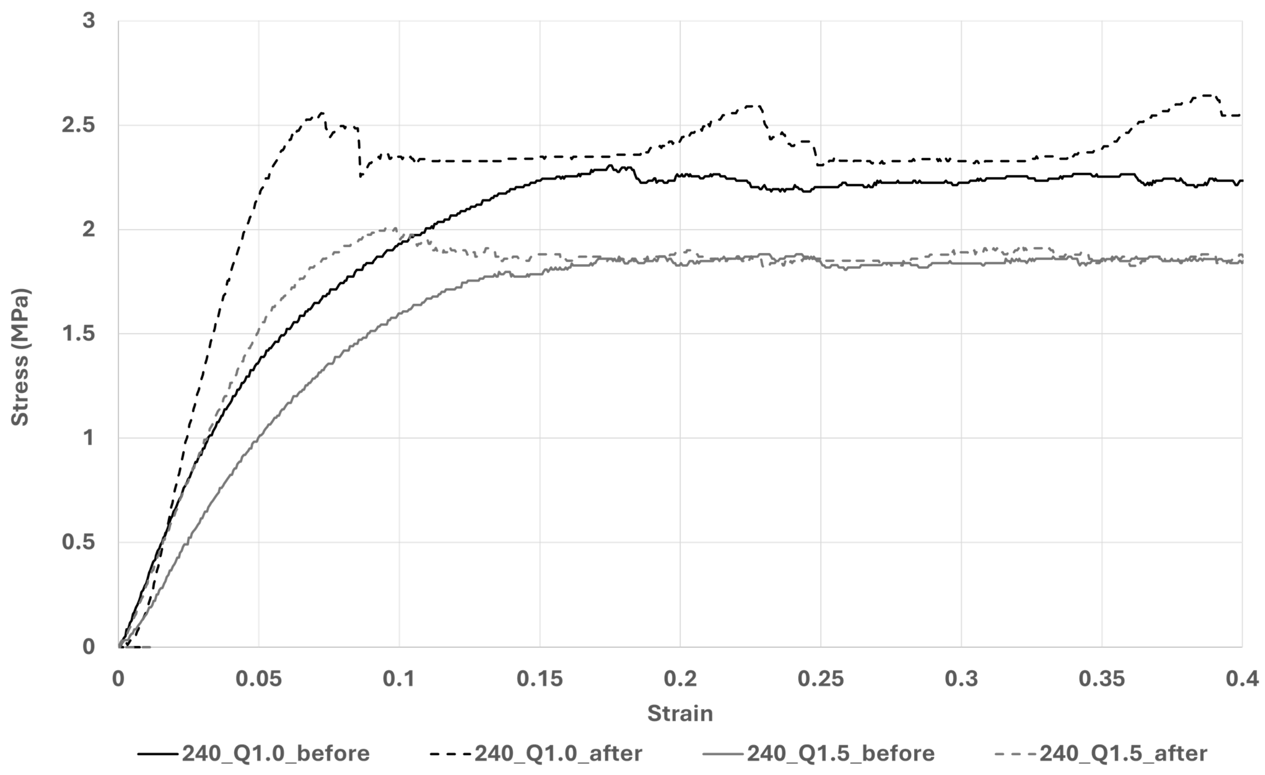
After undergoing cyclic testing, the 240 μm samples were subjected to a uniaxial tensile test to assess the material’s damage. This is to infer how much of the material’s original strength remains after it has been subjected to cyclic loading. Figure 8 shows the stress-strain curves of the 240 μm filament diameter meshes of both 1.5 and 1 mm pore sizes before and after performing cyclic testing.
The maximum stress values and Young’s modulus calculated before and after the cyclic tests are presented in Table 4 for each pore size, as well as the variation, in percentage, for each of these measures. The results indicate an increase in both the maximum stress and Young’s modulus following cyclic loading.

3.4. Preparation of PCL Meshes Loaded with Az

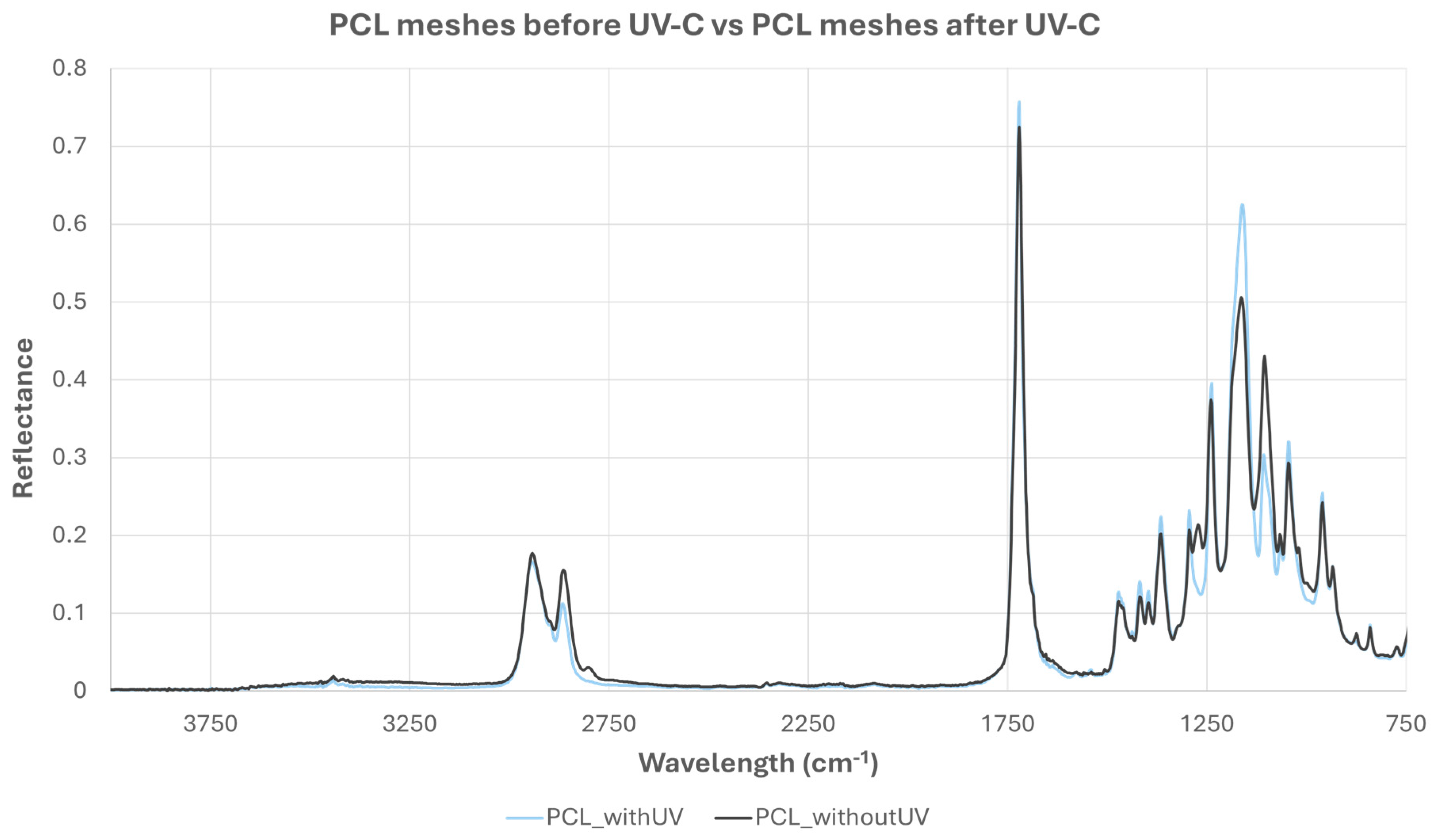
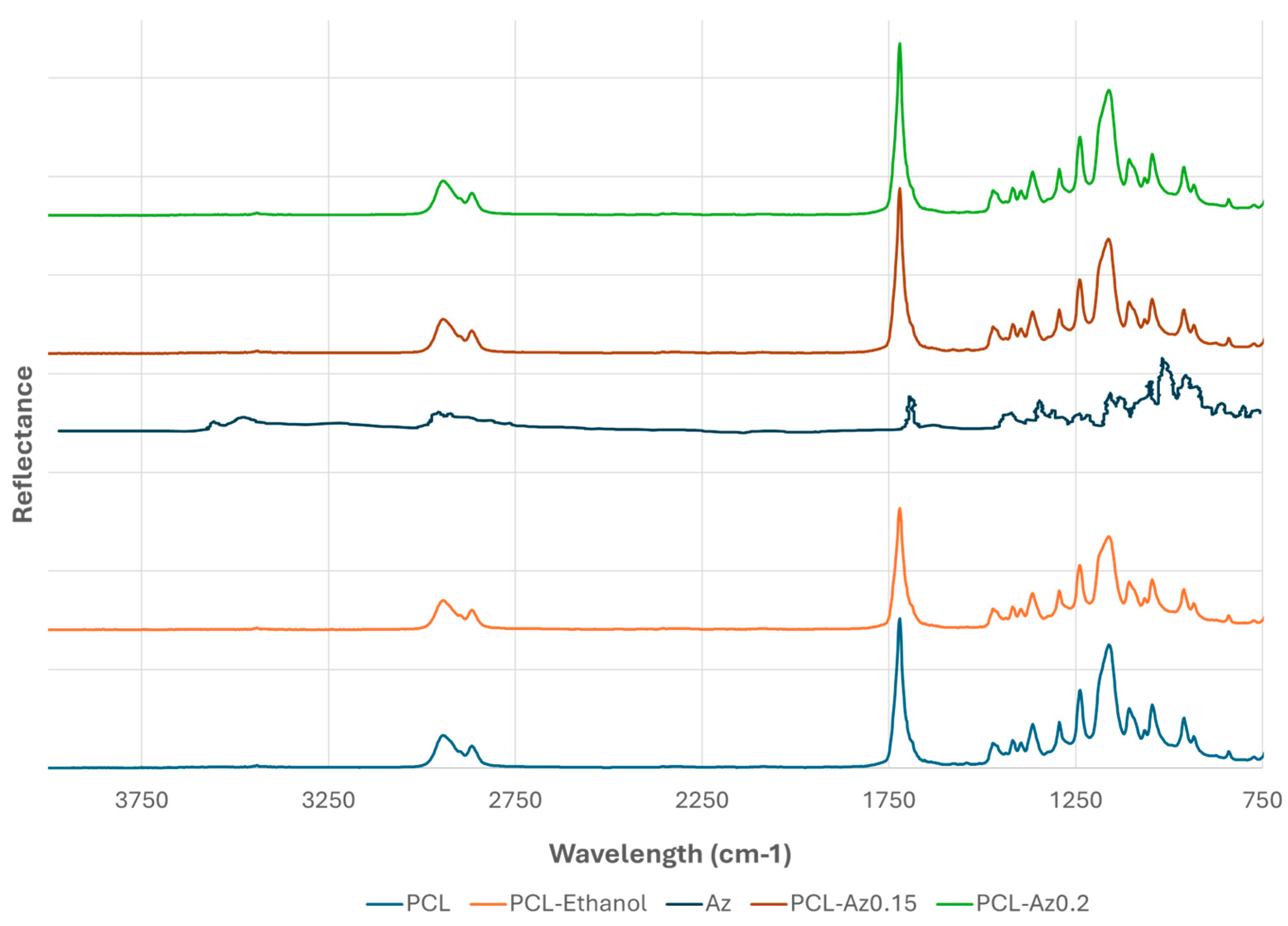
FTIR spectra were obtained for both the PCL meshes sterilized under UV-C light and for PCL meshes that did not go through this stage. This was performed to infer if UV-C exposure affected PCL’s chemical structure. In Figure 9, it can be observed that the PCL spectrum after UV-C sterilization presents slight alterations compared to the spectrum before sterilization. However, it was not drastically altered. However, it was not drastically altered. Since the samples with azithromycin also went through this process, the control spectrum for PCL-Az meshes was therefore obtained from UV-C-sterilized PCL samples to ensure consistency. Azithromycin’s FTIR spectrum is represented in Figure 10 alongside the spectra for PCL and PCL-Az.
The FTIR spectrum shows characteristic peaks at 2943 cm−1 (asymmetric CH3 stretching), 2866 cm−1 (symmetric CH2 stretching), 1721 cm−1 (C=O stretching), and in the range of 1471 to 732 cm−1 (combination of bending, wagging, twisting, and stretching vibrations of CH2 groups; C–O and C–C bonds) [31]. Regarding the Az spectrum, obtained from the literature [32], it is possible to observe that the main difference to PCL’s spectrum, regarding peaks location, is the peak present around a 3500 cm−1 wavelength, related to O−H and N–H stretching [33]. However, in both PCL-Az0.15 and PCL-Az0.2 spectra, only the PCL peaks are consistent, not being possible to identify this characteristic azithromycin peak, and there are no relevant differences between the two concentrations. Therefore, the peaks of the FTIR spectrum obtained for PCL-Az samples matched those of the control.

3.5. Assessment of the Antimicrobial Effect Through the Zone of Inhibition

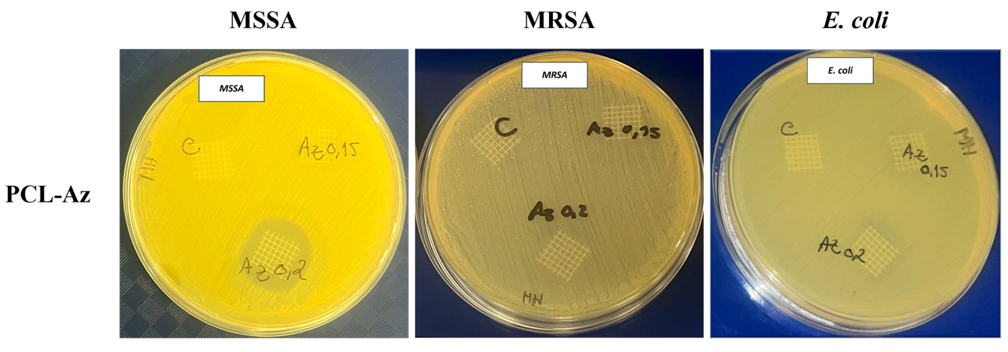
PCL-Az meshes’ antibacterial activity was assessed through evaluating the diameter of the inhibition zones formed around the samples, and the results were compared with the unloaded PCL mesh used as the control. Table 5 summarizes the inhibition zone diameters obtained for each bacterial strain tested. As shown in Figure 11, the PCL-Az0.15 mesh only exhibited inhibition against MSSA ATCC 29213, while the PCL-Az0.2 mesh demonstrated a broader antimicrobial effect, with inhibition zones also observed against E. coli ATCC 25922 and MSSA ATCC 29213. No inhibition was detected against MRSA ATCC 43300 for either concentration.

3.6. Evaluation of Biofilm Metabolic Activity and Biomass Reduction

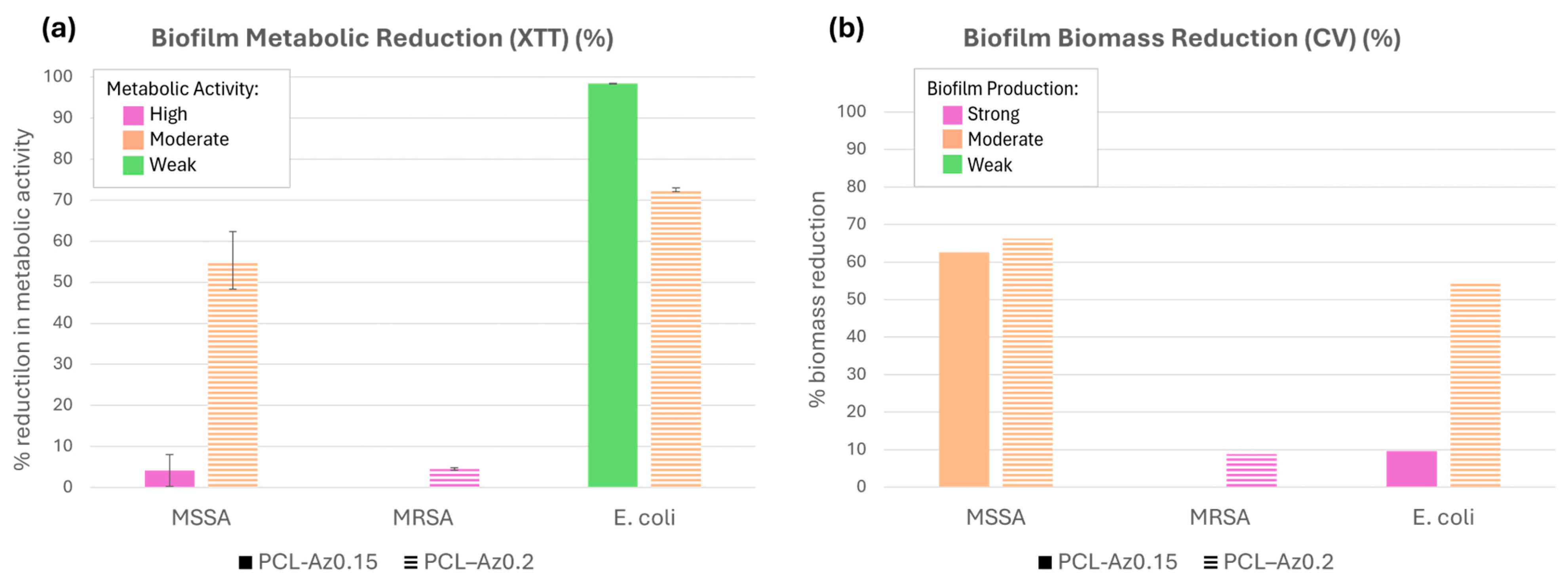
The outcomes of the tetrazolium salt and crystal violet assays are shown in Figure 12. Due to the absence of an inhibition zone for MRSA ATCC 43300 with the lower azithromycin concentration (0.15% w/w), biofilm assays were only performed using the higher concentration (0.20% w/w).
As classified by Lade et al. [34], the azithromycin concentration of 0.15% w/w resulted in a slight reduction in metabolic activity and a moderate decrease in biofilm biomass for MSSA. Conversely, this concentration promoted a significant reduction in E. coli biofilms, both in terms of metabolic activity and biomass. Regarding the 0.20% w/w concentration, moderate reductions were observed in both parameters for MSSA and E. coli, but the reduction was lower when compared to the 0.15% w/w results in E. coli.
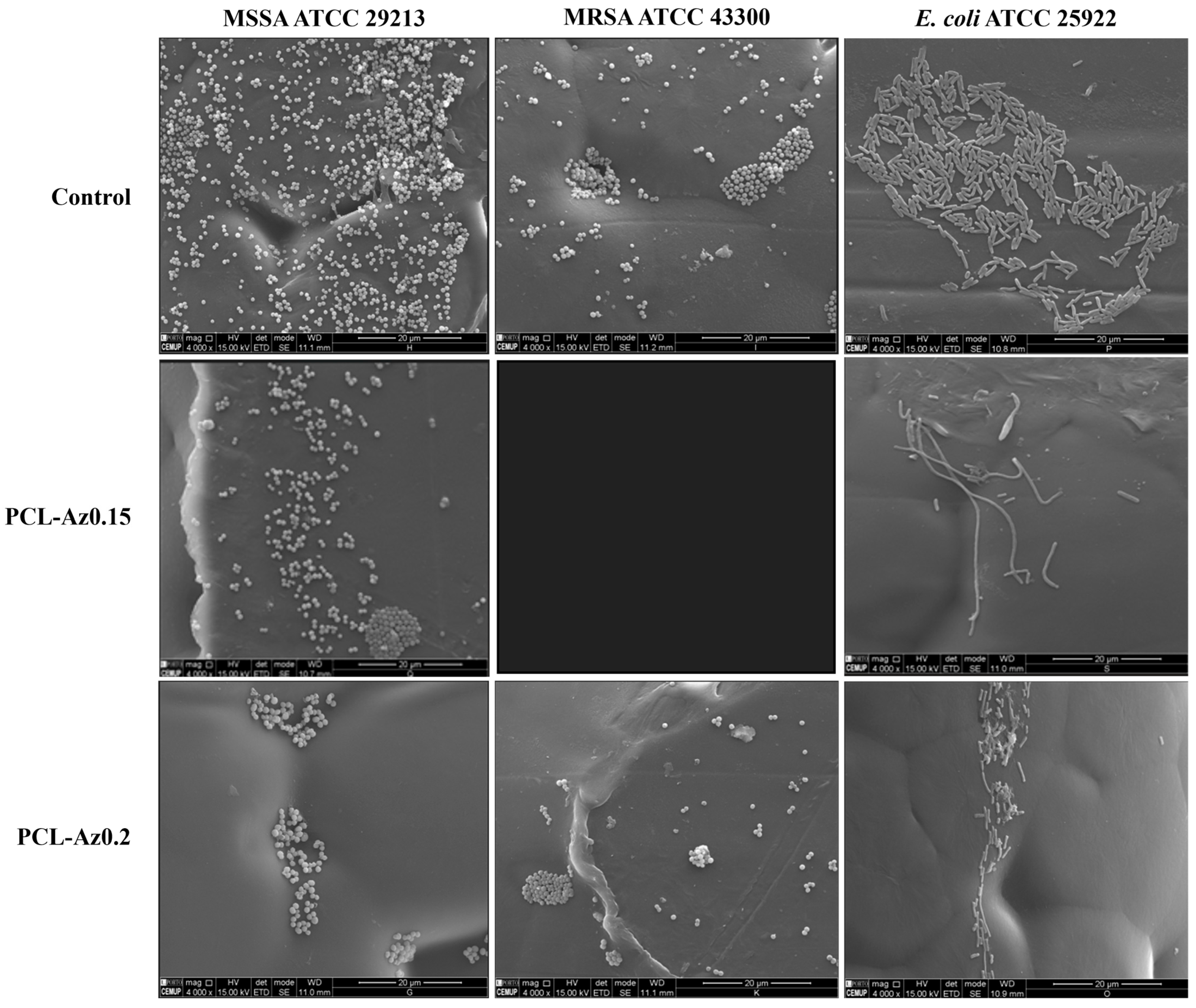
Figure 13 presents Scanning Electron Microscopy images showing that meshes incorporating azithromycin have visibly reduced bacterial presence, in agreement with the biofilm assays.

4. Discussion

Synthetic meshes often present challenges due to their limited biocompatibility and suboptimal biomechanical behavior, which can promote bacterial colonization and subsequent infections. To address these limitations, biodegradable meshes have emerged as promising alternatives for POP repair. Their fabrication via 3D printing enables the development of more compliant and less rigid structures, potentially reducing adverse outcomes [12,21,22]. In this study, we analyzed the performance of biodegradable meshes fabricated through melt electrowriting using 240 µm PCL filaments and two different pore sizes (1.0 mm and 1.5 mm). Mechanical behavior was assessed by uniaxial tensile testing to determine whether the stiffness of the meshes was appropriate, and cyclic loading tests were performed to evaluate their durability under physiological conditions. This analysis aimed to identify which configuration exhibits more favorable long-term mechanical performance. These were also compared to the Restorelle® meshes’ mechanical properties. The results obtained for the uniaxial tensile tests display the initially elastic region, where the mesh can still return to its original position despite being deformed, where the stress–strain relationship is approximately linear, with the slope representing the Young’s modulus. Once the yield stress is reached, the material behavior switches from elastic to plastic, from which the deformation becomes permanent, and the stress–strain curve starts to form a curve-like shape until it reaches a maximum stress value, stabilizing. Similar behavior is observed in the PCL meshes, suggesting that plastic properties are governed mainly by the material and sample geometry, not by pore size.
The maximum stresses obtained from uniaxial tensile tests indicate that the 240 µm diameter mesh with 1.0 mm pores resisted plastic deformation better than the 1.5 mm mesh, sustaining about 19% higher stress. This trend was consistent with the previous results for 2.0 mm pore meshes [21]. When analyzing the commercial Restorelle® mesh, a significantly higher stiffness was observed, with a stress value of 3.62 MPa at 20% strain—corresponding to the upper limit of the comfort zone. In contrast, the 240 µm PCL meshes with 1.0 mm and 1.5 mm pores reached 2.26 MPa and 1.84 MPa, respectively, at the same strain. Although these values are lower than those of Restorelle®, they are closer to the stress levels reported for vaginal tissues under similar strain, which are approximately 0.56 MPa for anterior and 0.36 MPa for posterior prolapse [13]. The stiffness mismatch between Restorelle® and human vaginal tissue exceeds 85–90%, which may contribute to mechanical incompatibility and increase the likelihood of tissue erosion. Conversely, smaller pores improved the load-bearing capacity of the samples before failure, suggesting that pore geometry plays a crucial role in adjusting mechanical behavior to better match the target tissue. This observation supports previous reports indicating that decreasing fiber diameter also reduces the stiffness of the structure [21]. These findings may guide future work on optimizing mesh architecture, including fiber diameter and pore size, to improve biomechanical compatibility for POP treatment. Additionally, new geometries, such as sinusoidal patterns that better replicate the behavior of vaginal tissue, are under investigation [22]. It is important to note, however, that uniaxial testing does not fully replicate the complex, multiaxial loading environment of the pelvic floor. Future research should incorporate biaxial mechanical testing and finite element simulations to better mimic in vivo loading conditions and validate mesh performance under physiologically relevant scenarios.
Concerning the cyclic tests, it can be seen that the material has a cyclic creep behavior, a time-dependent and permanent deformation of a material under a constant load, since the plastic deformation accumulates, and the curves do not go back to the same displacement [35,36]. This is a common result in polymers due to their viscous material behavior [37]. In the first cycle, the behavior is not linear, due to the polymer’s chain alignment, and possibly plastic deformation. The results obtained show that the first cycle is the one that causes more damage to the mesh since the area of the loop gradually decreases with the number of cycles, suggesting that the material undergoes hardening when plastic deformation occurs [38]. While the loads experienced by materials in the pelvic floor have not been extensively studied, Roman et al. established that vaginal tissues can tolerate a strain rate of up to 25% without sustaining damage. Based on the calculated average strain variations, all samples show strain variations below 2%, which is significantly lower. This indicates that the mesh deformations are well-suited for their intended purpose [28]. Calculating the strain the samples were subjected to in each cycle shows a trend towards strain stabilization with low strain increase. Even though the meshes underwent significant strain in the first cycles, the material response to cyclic loading becomes more stable and predictable through time. For each cycle of the cyclic loading, it is possible to observe that at the same maximum stress, the maximum strain reached increases, for both types of meshes. These results also can be an indication of the creep behavior mentioned before. The meshes with 1.0 mm pore size at a higher maximum stress suffer less strain than the meshes with 1.5 mm pore size, once again showing that the smaller the pore size, the stiffer the mesh. Because, in the cyclic tests, the meshes presented plastic deformation, tensile tests were performed to check the material’s damage. These tests showed increases in maximum stress (13% and 6.5%) and Young’s modulus (19.2% and 29.3%) for meshes with 1.0 mm and 1.5 mm pore sizes, respectively, when subjected to cyclic loading conditions.
These tensile tests reveal that they presented greater rigidity, compared to before the cyclic loading conditions. In another study, Barriere et al. verified this same behavior for solid polymers, where after cyclic loading, the material exhibited apparent strain hardening, derived from cyclic creep [39]. Although cyclic loading was limited to 100 cycles at 80% of the maximum stress in this study—consistent with previous work in the field [28]—future investigations should extend testing to higher cycle counts and more physiologically realistic loading scenarios. This is essential to assess the long-term mechanical durability and performance of the developed meshes under in vivo conditions.
FTIR analysis of the PCL meshes before and after the sterilization process was conducted to confirm whether the material maintained the biochemical characteristics after exposure to UV-C light. The peaks identified in the PCL meshes that underwent UV-C light are similar to those of the PCL meshes that did not go through this process. The minor variations in peak intensity suggest slight degradation in the PCL structure due to UV-C exposure, but the overall chemical structure of the polymer remains intact. The absence of new peaks or significant shifts indicates minimal chemical changes due to UV-C exposure.
In azithromycin-loaded meshes, a reduction in PCL-related peak intensity was observed, which may indicate the presence of additional compounds, although no distinct new peaks or functional group shifts were identified. This aligns with the spectra of both PCL-Az0.15 and PCL-Az0.2 samples, where no definitive azithromycin peaks were detected. These spectral variations alone are insufficient to confirm drug incorporation [40]. According to the literature, the main spectral feature of azithromycin is a broad band near the range of 3500–3000 cm−1, corresponding to O–H and N–H stretching [32,33]. This band was absent in our FTIR results, possibly due to low drug content or peak overlap. Therefore, while FTIR suggests no major disruption to the PCL structure, it may not be sensitive enough to confirm the presence of azithromycin in this context.
The XTT and CV assays provided complementary insights into biofilm formation. Regarding MSSA, SEM analysis revealed a significant reduction in biofilm content in the two azithromycin-loaded PCL-Az samples, when compared to the control group, which is consistent with the zone of inhibition data confirming antimicrobial effectiveness in both tested concentrations.
The XTT and CV data show an agreement for the PCL-Az0.2 meshes. However, with the 0.15% azithromycin formulation, a greater number of viable cells were detected, although with weaker biofilm strength. This may be due to the bacteria being in an early growth phase, leading to reduced extracellular matrix formation and diminished biofilm structure [41]. The PCL-Az0.2 formulation demonstrated higher effectiveness against MSSA, as shown by moderate biofilm formation and strong metabolic activity, corroborated by SEM images. These findings indicate that azithromycin may be more effective against planktonic bacteria. However, as bacteria transition into mature biofilm structures, the resistance increases, reducing drug efficacy [42]. MRSA, known for its strong multidrug resistance [43], demonstrated high metabolic activity and robust biofilm production, even in the presence of 0.2% azithromycin. SEM analysis confirmed its resilience, highlighting the need for higher drug concentrations to achieve significant antimicrobial effects. Finally, the SEM images of E. coli confirmed a decrease in biofilm content when exposed to azithromycin. Notably, the 0.2% formulation showed greater efficacy than the 0.15% one. This aligns with the zone of inhibition data, but not with the CV assay, which may be due to bacterial aggregation or reduced matrix visibility. XTT data reveal high metabolic activity, even at lower concentrations, suggesting that E. coli remained metabolically active despite reduced visible biofilm. This discrepancy may be explained by limitations in the detection of less structured biofilms through CV analysis [41]. Notably, the highest azithromycin concentration resulted in lower metabolic activity in the XTT assay than the lowest, which may suggest a potential sample swap or experimental variation. At 0.2% azithromycin, E. coli exhibited reduced biofilm and metabolic activity, corroborated by SEM images, although the effect was moderate. The narrow inhibition zones observed suggest that Az has only a slight antibacterial effect on E. coli 25922. Furthermore, the 0.15% concentration showed high biofilm production but low metabolic activity. This might be due to persistent extracellular material or the presence of non-dividing cells, which are often harder to detect via SEM imaging. These cells can form elongated, filamentous structures—commonly observed when bacteria are under stress—resulting in atypical cell division patterns known as “filamentation.” This process may be induced by unfavorable conditions, such as temperature shifts, antibiotic pressure, or genetic mutations [44]. The lack of inhibition at lower drug concentrations indicates insufficient antibacterial activity against resistant bacteria, such as azithromycin-resistant strains [45]. Nevertheless, the findings suggest that some antibacterial activity may still be present even at low concentrations. While azithromycin-loaded PCL meshes showed antimicrobial effects, the amount of drug incorporated was not quantified in this study. Therefore, further investigation is necessary, particularly involving immersion-based release studies and a comparison with the final drug content to assess drug loading accuracy. In future work, analytical techniques, such as UV-Vis spectrophotometry or HPLC, should be used to evaluate drug incorporation, given the limited sensitivity of FTIR for this purpose. These techniques would allow researchers to differentiate between surface and embedded drugs, determine total concentrations, and correlate these findings with antimicrobial activity [46,47]. Such data will provide a clearer understanding of drug content and delivery, helping to establish stronger links between material design and therapeutic effectiveness.
Overall, the results demonstrate that incorporating azithromycin into PCL meshes was successfully achieved. Considering the complications often associated with mesh-based POP repair, particularly those related to infection, the prevention of biofilm formation is essential to minimize the risk of mesh failure and reduce the likelihood of mesh removal procedures.

5. Conclusions

This work demonstrated the potential in applying MEW for the fabrication of surgical meshes, with better biocompatibility with vaginal tissues, and more similar mechanical characteristics. It is possible to conclude that meshes with higher pore sizes are the closest to the vaginal tissue’s behavior, being less stiff than the commercial mesh. Also, the meshes were able to sustain cyclic loading, only suffering deformation and resisting failure, with an increase in stiffness afterward.
However, the square geometry of the meshes limits their mechanical behavior, being important to test new geometries, until it is possible to closely match the vaginal tissue behavior. Another important evaluation to perform in the future is cyclic fatigue tests to understand the fatigue properties of the meshes.
Finally, coating these mesh implants with antimicrobial agents, in this case azithromycin, can inhibit and prevent biofilm formation against some bacteria strains, preventing mesh infection. Drug incorporation allied with meshes with appropriate mechanical characteristics can allow a better outcome in surgical mesh implantation for treatment of POP. However, further studies are needed, including drug release kinetics and the quantitative analysis of drug incorporation, to better validate the effectiveness of this approach.

Author Contributions

Conceptualization, S.C.d.O., A.A.F. and E.S.; methodology, J.P.M., A.S.S., S.C.d.O. and E.S.; software, J.P.M. and A.S.S.; investigation, J.P.M., A.S.S., S.C.d.O. and E.S.; resources, S.C.d.O., A.A.F. and E.S.; writing—original draft preparation, J.P.M.; writing—review and editing, S.C.d.O., A.A.F. and E.S.; visualization, J.P.M.; supervision, S.C.d.O., A.A.F. and E.S.; funding acquisition, S.C.d.O., A.A.F. and E.S. All authors have read and agreed to the published version of the manuscript.

Funding

This work was funded by the Stimulus of Scientific Employment 2021.00077.CEECIND and the project PRECOGFIL-PTDC/EMD-EMD/2229/2020, financed through FCT. This work was supported by FCT, through INEGI, under LAETA, projects UIDB/50022/2020 and UIDP/50022/2020, LA/P/0079/2020 and CINTESIS, R&D Unit, project UIDP/4255/2020.

Institutional Review Board Statement

Not applicable.

Informed Consent Statement

Not applicable.

Acknowledgments

The authors would like to acknowledge and thank the Faculties of Engineering and Medicine of the University of Porto and INEGI for allowing the development of this work and the Materials Center of the University of Porto for their contribution.

Conflicts of Interest

The authors declare no conflicts of interest.

Abbreviations

The following abbreviations are used in this manuscript:
POPPelvic Organ Prolapse
PFDPelvic Floor Dysfunction
PPPolypropylene
PETPolyethylene Terephthalate
PCLPolycaprolactone
PLAPolylactic Acid
PUPolyurethane
ESElectrospinning
MEWMelt Electrospinning Writing
SEMScanning Electron Microscopy
AZAzithromycin
FTIRFourier Transform Infrared Spectroscopy
ATRAttenuated Total Reflectance
MSSAMethicillin Susceptible Staphylococcus Aureus
MRSAMethicillin Resistant Staphylococcus Aureus
BHBrain Heart
XTTTetrazolium Salt
CVCrystal Violet
PBSPhosphate-Buffered Saline
OPOptical Density

References

  1. Weintraub, A.Y.; Glinter, H.; Marcus-Braun, N. Narrative review of the epidemiology, diagnosis and pathophysiology of pelvic organ prolapse. Int. Braz. J. Urol. 2020, 46, 5–14. [Google Scholar] [CrossRef]
  2. Deng, Z.; Zhu, L.; Hu, X.; Fu, C.-W.; Xu, X.; Zhang, Q.; Qin, J.; Heng, P.-A. An international urogynecological association (IUGA)/international continence society (ICS) joint report on the terminology for female pelvic floor dysfunction. Neurourol. Urodyn. 2010, 29, 4–20. [Google Scholar] [CrossRef]
  3. Clinic, M. Pelvic Organ Prolapse. Available online: https://www.mayoclinic.org/diseases-conditions/pelvic-organ-prolapse/symptoms-causes/syc-20360557 (accessed on 4 June 2024).
  4. Ko, K.J.; Lee, K.-S. Current surgical management of pelvic organ prolapse: Strategies for the improvement of surgical outcomes. Investig. Clin. Urol. 2019, 60, 413–424. [Google Scholar] [CrossRef]
  5. Pelvic Organ Prolapse: Learn More—Surgery for Pelvic Organ Prolapse. In InformedHealth.org, Institute for Quality and Efficiency in Health Care (IQWiG): Cologne, Germany. 2006. Available online: https://www.ncbi.nlm.nih.gov/books/NBK525780/ (accessed on 22 August 2025).
  6. Dessie, S.G.; Shapiro, A.; Haviland, M.J.; Hacker, M.R.; Elkadry, E.A. Obliterative Versus Reconstructive Prolapse Repair for Women Older than 70: Is There an Optimal Approach? Female Pelvic Med. Reconstr. Surg. 2017, 23, 23–26. [Google Scholar] [CrossRef]
  7. Houman, J.; Weinberger, J.M.; Eilber, K.S. Native Tissue Repairs for Pelvic Organ Prolapse. Curr. Urol. Rep. 2017, 18, 6. [Google Scholar] [CrossRef] [PubMed]
  8. Yuan, M.; Hu, M.; Dai, F.; Fan, Y.; Deng, Z.; Deng, H.; Cheng, Y. Application of synthetic and natural polymers in surgical mesh for pelvic floor reconstruction. Mater. Des. 2021, 209, 109984. [Google Scholar] [CrossRef]
  9. Mancuso, E.; Downey, C.; Doxford-Hook, E.; Bryant, M.G.; Culmer, P. The use of polymeric meshes for pelvic organ prolapse: Current concepts, challenges, and future perspectives. J. Biomed. Mater. Res. Part B Appl. Biomater. 2019, 108, 771–789. [Google Scholar] [CrossRef] [PubMed]
  10. Baylón, K.; Rodríguez-Camarillo, P.; Elías-Zúñiga, A.; Díaz-Elizondo, J.A.; Gilkerson, R.; Lozano, K. Past, Present and Future of Surgical Meshes: A Review. Membranes 2017, 7, 47. [Google Scholar] [CrossRef]
  11. Food and Drug Administration. Urogynecologic Surgical Mesh Implants. Available online: https://www.fda.gov/medical-devices/implants-and-prosthetics/urogynecologic-surgical-mesh-implants (accessed on 10 May 2025).
  12. Rynkevic, R.; Silva, M.; Martins, P.; Mascarenhas, T.; Alves, J.; Fernandes, A. Characterisation of polycaprolactone scaffolds made by melt electrospinning writing for pelvic organ prolapse correction—A pilot study. Mater. Today Commun. 2022, 32, 104101. [Google Scholar] [CrossRef]
  13. Seifalian, A.; Basma, Z.; Digesu, A.; Khullar, V. Polypropylene Pelvic Mesh: What Went Wrong and What Will Be of the Future? Biomedicines 2023, 11, 741. [Google Scholar] [CrossRef]
  14. Mangir, N.; Roman, S.; Chapple, C.R.; MacNeil, S. Complications related to use of mesh implants in surgical treatment of stress urinary incontinence and pelvic organ prolapse: Infection or inflammation? World J. Urol. 2019, 38, 73–80. [Google Scholar] [CrossRef]
  15. Mellano, E.M.; Nakamura, L.Y.; Choi, J.M.; Kang, D.C.; Grisales, T.; Raz, S.; Rodriguez, L.V. The Role of Chronic Mesh Infection in Delayed-Onset Vaginal Mesh Complications or Recurrent Urinary Tract Infections. Female Pelvic Med. Reconstr. Surg. 2016, 22, 166–171. [Google Scholar] [CrossRef]
  16. Pfizer Labs. Zithromax® (Azithromycin) for Injection, for Intravenoususe. U.S. Food and Drug Administration. 2022. Available online: https://www.accessdata.fda.gov/drugsatfda_docs/label/2022/050733Orig1s049lbl.pdf (accessed on 17 May 2024).
  17. Ren, J.; Murray, R.; Wong, C.S.; Qin, J.; Chen, M.; Totsika, M.; Riddell, A.D.; Warwick, A.; Rukin, N.; Woodruff, M.A. Development of 3D Printed Biodegradable Mesh with Antimicrobial Properties for Pelvic Organ Prolapse. Polymers 2022, 14, 763. [Google Scholar] [CrossRef]
  18. Bhardwaj, N.; Kundu, S.C. Electrospinning: A fascinating fiber fabrication technique. Biotechnol. Adv. 2010, 28, 325–347. [Google Scholar] [CrossRef] [PubMed]
  19. Xue, J.; Wu, T.; Dai, Y.; Xia, Y. Electrospinning and Electrospun Nanofibers: Methods, Materials, and Applications. Chem. Rev. 2019, 119, 5298–5415. [Google Scholar] [CrossRef] [PubMed]
  20. Vaz, M.F.R.; Martins, J.A.P.; Pinheiro, F.; Ferreira, N.M.; Brandão, S.; Alves, J.L.; Fernandes, A.A.; Parente, M.P.L.; Silva, M.E.T. Medical- and Non-Medical-Grade Polycaprolactone Mesh Printing for Prolapse Repair: Establishment of Melt Electrowriting Prototype Parameters. Appl. Sci. 2024, 14, 9670. [Google Scholar] [CrossRef]
  21. Vaz, M.F.; Martins, J.A.P.; Pinheiro, F.; Ferreira, N.M.; Brandão, S.; Alves, J.L.; Fernandes, A.A.; Parente, M.P.L.; Silva, M.E. Optimizing melt electrowriting prototypes for printing non-medical and medical grade polycaprolactone meshes in prolapse repair. J. Appl. Polym. Sci. 2024. [Google Scholar] [CrossRef]
  22. Sterk, S.; Silva, M.E.T.; Fernandes, A.A.; Huß, A.; Wittek, A. Development of new surgical mesh geometries with different mechanical properties using the design freedom of 3D printing. J. Appl. Polym. Sci. 2024, 142, e56408. [Google Scholar] [CrossRef]
  23. da Cunha, M.N.B.; Rynkevic, R.; da Silva, M.E.T.; Brandão, A.F.M.d.S.; Alves, J.L.; Fernandes, A.A. Melt Electrospinning Writing of Mesh Implants for Pelvic Organ Prolapse Repair. 3D Print. Addit. Manuf. 2022, 9, 389–398. [Google Scholar] [CrossRef]
  24. Martins, J.P.; da Silva, E.T.; Fernandes, A.A.; de Oliveira, S.C. Three-Dimensional Melted Electrowriting Drug Coating Fibers for the Prevention of Device-Associated Infections: A Pilot Study. Bioengineering 2024, 11, 636. [Google Scholar] [CrossRef]
  25. ISO 1183-1:2025; Plastics—Methods for Determining the Density of Non-Cellular Plastics—Part 1: Immersion Method, Liquid Pycnometer Method and Titration Method. International Organization for Standardization: Geneva, Switzerland, 2025.
  26. Kade, J.C.; Dalton, P.D. Polymers for Melt Electrowriting. Adv. Healthc. Mater. 2020, 10, e2001232. [Google Scholar] [CrossRef]
  27. Qin, J.; Chen, Y.; Guo, X.; Huang, Y.; Chen, G.; Zhang, Q.; He, G.; Zhu, S.; Ruan, X.; Zhu, H. Regulation of Hard Segment Cluster Structures for High-performance Poly(urethane-urea) Elastomers. Adv. Sci. 2024, 11, e2400255. [Google Scholar] [CrossRef]
  28. Roman, S.; Mangir, N.; Hympanova, L.; Chapple, C.R.; Deprest, J.; MacNeil, S. Use of a simple in vitro fatigue test to assess materials used in the surgical treatment of stress urinary incontinence and pelvic organ prolapse. Neurourol. Urodyn. 2018, 38, 107–115. [Google Scholar] [CrossRef]
  29. de Sousa Martins, P.A.L. Experimental and Numerical Studies of Soft Biological Tissues. Ph.D. Thesis, Faculty of Engineering of the University of Porto, Porto, Portugal, 2010. [Google Scholar]
  30. Klinge, U.; Otto, J.; Mühl, T. High Structural Stability of Textile Implants Prevents Pore Collapse and Preserves Effective Porosity at Strain. BioMed Res. Int. 2015, 2015, 1–7. [Google Scholar] [CrossRef]
  31. Elzein, T.; Nasser-Eddine, M.; Delaite, C.; Bistac, S.; Dumas, P. FTIR study of polycaprolactone chain organization at interfaces. J. Colloid Interface Sci. 2004, 273, 381–387. [Google Scholar] [CrossRef]
  32. Robaina, N.F.; de Paula, C.E.R.; Brum, D.M.; de la Guardia, M.; Garrigues, S.; Cassella, R.J. Novel approach for the determination of azithromycin in pharmaceutical formulations by Fourier transform infrared spectroscopy in film-through transmission mode. Microchem. J. 2013, 110, 301–307. [Google Scholar] [CrossRef]
  33. Bhadra, S. Formulation & process development of azithromycin ophthalmic nanosuspension. Int. J. Pharm. Pharm. Sci. 2013, 5, 490–497. [Google Scholar]
  34. Lade, H.; Park, J.H.; Chung, S.H.; Kim, I.H.; Kim, J.-M.; Joo, H.-S.; Kim, J.-S. Biofilm Formation by Staphylococcus aureus Clinical Isolates is Differentially Affected by Glucose and Sodium Chloride Supplemented Culture Media. J. Clin. Med. 2019, 8, 1853. [Google Scholar] [CrossRef] [PubMed]
  35. Głuchowski, A.; Sas, W. Long-Term Cyclic Loading Impact on the Creep Deformation Mechanism in Cohesive Materials. Materials 2020, 13, 3907. [Google Scholar] [CrossRef]
  36. Callister, W.D.; Rethwisch, D.G. Materials Science and Engineering: An Introduction, 10th ed.; Wiley: Hoboken, NJ, USA, 2018. [Google Scholar]
  37. Vinogradov, A.M.; Schumacher, S. Cyclic Creep of Polymers and Polymer-Matrix Composites. Mech. Compos. Mater. 2001, 37, 29–34. [Google Scholar] [CrossRef]
  38. Liu, H.; Zhang, L.; Lu, K.; Gao, B. Study of Cyclic Plasticity and Creep Ratchet Behavior of PTFE. Appl. Sci. 2023, 13, 10039. [Google Scholar] [CrossRef]
  39. Barriere, T.; Gabrion, X.; Holopainen, S.; Jokinen, J. Testing and analysis of solid polymers under large monotonic and long-term cyclic deformation. Int. J. Plast. 2020, 135, 102781. [Google Scholar] [CrossRef]
  40. Bradley, M.; Izzia, F.; Nunn, S. Analysis of Mixtures by FT-IR: Spatial and Spectral Separation of Complex Samples. Available online: https://www.spectroscopyonline.com/view/analysis-mixtures-ft-ir-spatial-and-spectral-separation-complex-samples (accessed on 22 August 2025).
  41. Xu, Z.; Liang, Y.; Lin, S.; Chen, D.; Li, B.; Li, L.; Deng, Y. Crystal Violet and XTT Assays on Staphylococcus aureus Biofilm Quantification. Curr. Microbiol. 2016, 73, 474–482. [Google Scholar] [CrossRef] [PubMed]
  42. Høiby, N.; Henneberg, K.; Wang, H.; Stavnsbjerg, C.; Bjarnsholt, T.; Ciofu, O.; Johansen, U.R.; Sams, T. Formation of Pseudomonas aeruginosa inhibition zone during tobramycin disk diffusion is due to transition from planktonic to biofilm mode of growth. Int. J. Antimicrob. Agents 2019, 53, 564–573. [Google Scholar] [CrossRef] [PubMed]
  43. Bhattacharya, S.; Bir, R.; Majumdar, T. Evaluation of Multidrug Resistant Staphylococcus aureus and their Association with Biofilm Production in a Tertiary Care Hospital, Tripura, Northeast India. J. Clin. Diagn. Res. 2015, 9, DC01-4. [Google Scholar] [CrossRef]
  44. Cayron, J.; Dedieu-Berne, A.; Lesterlin, C. Bacterial filaments recover by successive and accelerated asymmetric divisions that allow rapid post-stress cell proliferation. Mol. Microbiol. 2023, 119, 237–251. [Google Scholar] [CrossRef]
  45. Bizot, E.; Cointe, A.; Bidet, P.; Mariani-Kurkdjian, P.; Hobson, C.A.; Courroux, C.; Liguori, S.; Bridier-Nahmias, A.; Magnan, M.; Merimèche, M.; et al. Azithromycin Resistance in Shiga Toxin-Producing Escherichia coli in France between 2004 and 2020 and Detection of mef (C)- mph (G) Genes. Antimicrob. Agents Chemother. 2022, 66, e0194921. [Google Scholar] [CrossRef]
  46. Yassin, A.E.; Albekairy, A.M.; Omer, M.; Almutairi, A.; Alotaibi, Y.; Althuwaini, S.; Alaql, O.A.; Almozaai, S.S.; Almutiri, N.M.; Alluhaim, W.; et al. Chitosan-Coated Azithromycin/Ciprofloxacin-Loaded Polycaprolactone Nanoparticles: A Characterization and Potency Study. Nanotechnol. Sci. Appl. 2023, 16, 59–72. [Google Scholar] [CrossRef]
  47. Hamzehloo, M.; Karimi, J.; Eghbali, N.; Mirzakhani, M.; Aghapoor, K.; Darabi, H.R. A new blend of polymeric encapsulation of azithromycin by spray-drying with a pH responsive in drug release. Dry. Technol. 2017, 35, 1688–1695. [Google Scholar] [CrossRef]
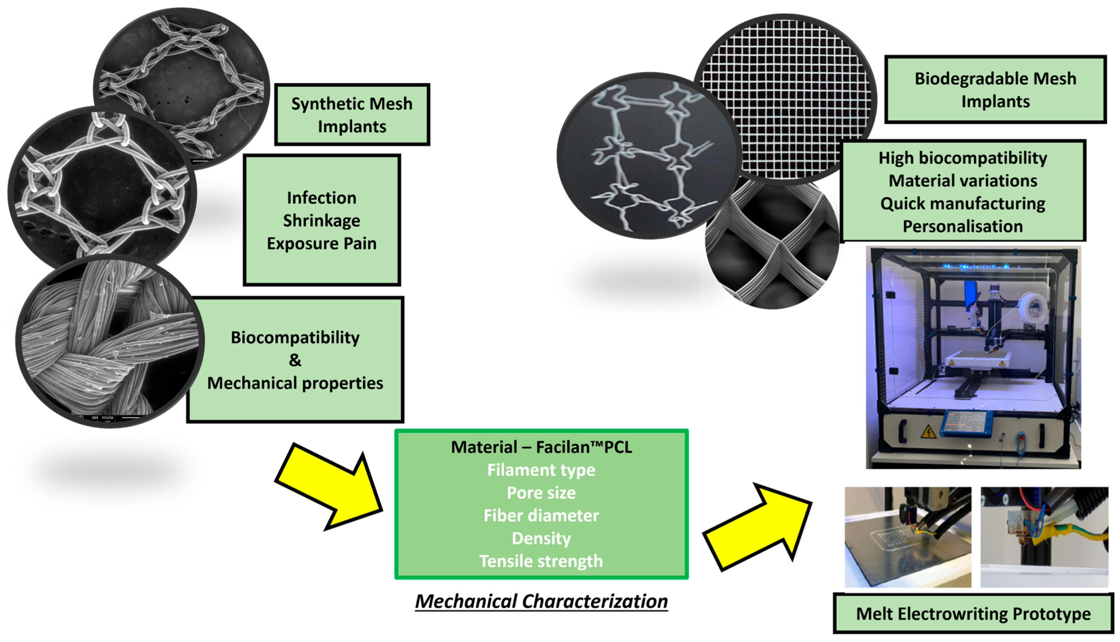
Figure 1. Schematic objective of this study.
Applsci 15 09436 g001
Figure 2. (a) Representation of the G-Code mesh (square-shaped geometry); (b) MEW device; (c) square-shaped geometry.
Applsci 15 09436 g002
Figure 3. Scanning Electron Microscopy (SEM) image of Restorelle® mesh.
Applsci 15 09436 g003
Figure 4. Uniaxial test set up for single fibers: (a) MultiTest-I, Mecmesin GmbH, Germany; (b) ILC 10N, Mecmesin GmbH, Germany; and clamp system (c) mesh sample fixed between clamps.
Applsci 15 09436 g004
Figure 5. Stress–strain responses from tensile tests on 240 µm meshes with pore sizes of 1.0, 1.5, and 2.0 mm (240_Q1.0, 240_Q1.5, 240_Q2.0), compared to anterior and posterior human vaginal tissue and the commercial Restorelle® mesh. The “comfort zone” is also indicated, representing typical strain levels during daily activities.
Applsci 15 09436 g005
Figure 6. Stress–strain curve obtained from cyclic tests of (a) 240 µm samples with 1.0 mm pores; (b) 240 µm samples with 1.5 mm pores.
Applsci 15 09436 g006
Figure 7. Maximum strain reached under maximum stress conditions for each cycle in the (a) 240 µm mesh with 1.0 mm pores and (b) 240 µm mesh with 1.5 mm pores. These values correspond to the strain observed at the peak load in each of the 100 loading cycles.
Applsci 15 09436 g007
Figure 8. Effect of cyclic loading conditions on 240 µm samples with 1.5 and 1.0 mm pores.
Applsci 15 09436 g008
Figure 9. FTIR spectrum of PCL meshes that were sterilized under UV-C light and PCL meshes that were not subjected to this process.
Applsci 15 09436 g009
Figure 10. PCL, PCL-Ethanol, Az, and PCL-Az meshes’ FTIR spectra.
Applsci 15 09436 g010
Figure 11. Inhibition zones of PCL-Az meshes against three bacterial strains.
Applsci 15 09436 g011
Figure 12. (a) Metabolic activity reduction (%) assessed by XTT assay for biofilm formation of MSSA, MRSA, and E. coli; (b) biomass reduction (%) assessed by CV assay for the same bacterial strains.
Applsci 15 09436 g012
Figure 13. SEM images of control, PCL-Az0.15, and PCL-Az0.2 meshes against MSSA ATCC 29213, MRSA ATCC 43300, and E. coli ATCC 25922.
Applsci 15 09436 g013
Table 1. Optimized MEW printing parameters for the fabrication of 240 µm meshes.
ParameterValue
Temperature195 °C
Voltage3.23 kV
Speed825 mm/min
Height3 mm
Table 2. Maximum stress values within and outside the comfort zone, obtained from uniaxial tensile tests. PCL meshes with varying pore sizes, the Restorelle® mesh, and human anterior and posterior vaginal tissue [28,29]. The comfort zone corresponds to strains up to 20%.
VariablesPore Size (mm)σmax (MPa)σmax comfort zone (MPa)
240 µm diameter meshes1.02.312.26
1.51.881.84
Restorelle®2.09.023.62
Anterior Human Tissue_________5.300.56
Posterior Human Tissue_________3.200.36
Table 3. Average strain variation calculated between the 1st and the 100th in cyclic tests.
Filament Diameter (µm)Pore Size (mm)∆ε (%)
2401.00.73
1.51.79
Table 4. Maximum stress values and Young’s modulus obtained before and after cyclic loading and their variation.
Pore Size (mm)σmax (MPa)E (MPa)
Before Cyclic Loading1.02.3132.47
1.51.8823.43
After Cyclic Loading1.02.6540.19
1.52.0133.16
∆ (%)1.012.819.2
1.56.529.3
Table 5. Inhibition zone diameters (in mm) measured for PCL and PCL-Az mesh implants against (ATCC 29213), MRSA (ATCC 43300), and Escherichia coli (ATCC 25922).
MSSA 29213MRSA 43300E. coli 25922
Control group0 mm0 mm0 mm
PCL-Az0.1511 mm0 mm0 mm
PCL-Az0.235 mm0 mm22 mm
Disclaimer/Publisher’s Note: The statements, opinions and data contained in all publications are solely those of the individual author(s) and contributor(s) and not of MDPI and/or the editor(s). MDPI and/or the editor(s) disclaim responsibility for any injury to people or property resulting from any ideas, methods, instructions or products referred to in the content.