1. Introduction
A basic classification of primary shell structures for space applications may include three main categories: (1) heavily-loaded interstages for space launchers, (2) load-carrying spacecraft tubular bodies (central tubes) and cone adapters for medium-large satellites, and (3) thin-walled beam elements for the assembly of generic payloads. Proceeding from the first to the third category, the emphasis on the design progressively changes from strength and buckling issues to high stiffness-to-weight ratios and thermal stability requirements. On top of this classification, there are thin-walled beams used to assemble lightweight space structures, such as the articulated deployment booms for large antennas. In this case, stiffness and thermal stability requirements are dominating with respect to the load-carrying capability, leading to solutions in which the structural mass is minimized to the extreme.
The main design issue concerning this kind of application is the fact that the payload, equipment, flanges, and mechanisms may adversely affect the natural frequencies of the bare structure according to their size, position, and distribution. To counteract this fact, it is often necessary to increase the stiffness of the structure, that is, its mass. In the framework of preliminary design, most of these elements are conveniently simplified and simulated with the aid of rigid bodies and rigid connections. Rigid bodies, in turn, may be reduced to concentrated masses and moments of inertia. Essentially, this means that several variables and parameters are in principle involved in the preliminary design phase, which includes both structural and non-structural elements. To simulate and study all these options, separately or in conjunction, it is favorable to have good analytical predictions of the relative effects on the resulting natural frequencies. These predictions are also the basis for efficiently addressing minimum mass solutions of the shell-beam structure.
Although CFRP-layered shells and beams are commonly used in space applications, a competitive option is represented by CFRP Anisogrid structures, as demonstrated in [
1,
2]. Nevertheless, the majority of the research activities developed on this topic in the last two decades have been devoted to the first category of structures, i.e., aiming at buckling and strength issues. However, the inclusion of global stiffness requirements of the shell can significantly modify the optimal design with respect to the solution based on the loading capability only. This modification is apparent in the different helical angle of ribs, which represents the fundamental design variable, as shown in [
3] with reference to the axial stiffness effect. The axial, transverse, and bending deformability of Anisogrid cylindrical shells subjected to inertia loads have been analytically and numerically (FEM) addressed in [
4,
5,
6]. An optimization method based on FEM and genetic algorithms, aimed at handling multiple external loading and stiffness constraints of Anisogrid cylindrical shells, is reported in [
7]. The importance of the transverse stiffness requirement in determining the optimal design of the Anisogrid central tube prototype is demonstrated in [
8].
Overall, few studies have been devoted to the natural frequencies of Anisogrid lattice cylindrical shells, such as the works developed in [
9,
10], for a cantilever structure with a rigid disk attached to its free end, and for a structure clamped at both sides. The free vibration characteristics of grid-stiffened (i.e., including a skin) conical shells are investigated in [
11], whereas the fundamental frequency of Anisogrid lattice conical shells under arbitrary boundary conditions is studied in [
12].
Therefore, in order to contribute to this essential topic in lightweight applications, not necessarily limited to space, the natural frequencies of Anisogrid lattice cylindrical shell-beams carrying rigid bodies are investigated (1) for pure bending modes, in light of free-free, clamped–free, and clamped–clamped boundary conditions and (2) for two coupled modes, i.e., axial–bending and torsional-bending, in light of the clamped–free boundary condition.
In order to approach the analytical models in the simplest way, smeared elastic properties equivalent to the system of ribs are conveniently introduced along with the classical differential equations of the so-called “Timoshenko beam” that has inspired a number of papers over decades, such as the works reported in [
13,
14,
15,
16,
17,
18,
19,
20] to mention only a few. In fact, the regular and reasonably dense system of ribs that normally characterizes properly designed Anisogrid structures provides a nearly continuous behavior, which is reflected in representative global stiffness properties. This means that, from this point of view, the discrete nature of the Anisogrid structure can be effectively reduced to an equivalent orthotropic homogeneous skin, similarly to any balanced symmetric laminate. But on the contrary, this reduction may provide unsatisfactory results whenever the structure features a rather coarse system of ribs that actually emphasizes its discrete nature. The more or less close correspondence with the expected analytical results will be evaluated with the aid of FEM.
An example of an Anisogrid shell-beam segment is shown in the pictures of
Figure 1. This prototype was produced by means of interlaced high-modulus dry carbon fiber tows, supported by a “parallel winding” deposition strategy, followed by resin infusion under vacuum bag, and oven curing [
21].
2. Natural Frequencies and the Smeared Approach
The Anisogrid structure is characterized by a certain number of hoop and helical ribs regularly arranged along the axial direction and around the cross-section of the shell. For given values of the radius and the length of the cylindrical shell, each configuration is uniquely identified by the pair of integers n
h and n
se, which correspond to half the total number of helical ribs and the number of hoop sections, respectively, given that each hoop section is delimited by two consecutive hoop ribs. The angle formed by the helical ribs with the meridian of the shell is denoted with φ and represents the fundamental design variable, as follows:
The other variables are b
c, b
h, and t, which denote the width of hoop and helical ribs, and the radial thickness of ribs. When the configuration features a reasonably dense system of ribs, the structural behavior can be approximated with the aid of orthotropic equivalent smeared properties [
22]. In a simplified analytical modelling, however, only the equivalent axial modulus of elasticity E
x, the equivalent in-plane shear modulus G
xy, and the smeared mass density ρ are necessary, as follows:
in which E
h and E
c denote the modulus of elasticity of helical and hoop ribs in the fiber direction, and ρ
h and ρ
c the mass densities of such ribs. In fact, hoop and helical ribs could theoretically be made by interlacing two different kinds of fibers.
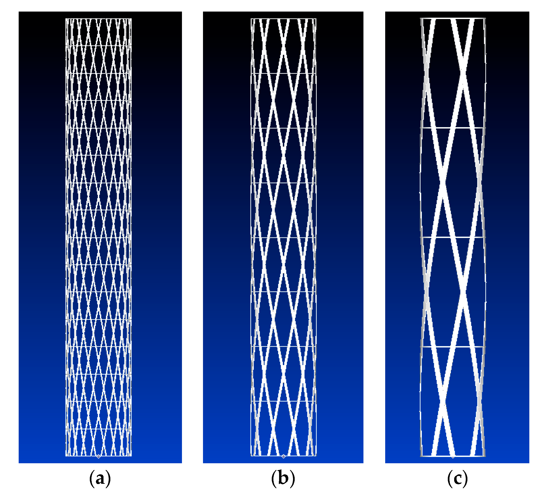
It is important to underline that the reduction in smeared properties can homogenize and make identical configurations with rather different spatial density of ribs which, as a consequence, may feature different structural behaviors. For example, the structures that are represented in
Figure 2 are identical in light of the smeared properties but not the same in terms of the natural frequencies, as will be shown in the later section. The point is that the smeared approach, by definition, cannot properly cover configurations that are clearly rough. On the contrary, this approach suggests moving toward configurations that are reasonably dense with ribs.
It is assumed that the shell-beams are equipped and support some rigid bodies that can be reduced to a concentrated mass m and a bending moment of inertia I about the axis orthogonal to the plane of deflection of the beam. The concentrated mass is positioned along the axis of the beam and is further characterized by the axial offset d from the edge section through a rigid link. This axial offset can assume both positive and negative values. In the former case, the concentrated mass is external to the beam; in the latter case it is internal. In addition to these schemes, a less common one foresees the mass m positioned with a transverse (radial) offset from the axis of the beam, denoted with r, thus providing a total torsional inertia term about the axis of the beam, denoted with It.
Therefore, according to the schemes reported in
Figure 3, four boundary conditions are actually developed: (1) clamped–free with mass, axial offset, and bending inertia at the free edge, (2) free–free with masses, axial offsets, and bending inertias at the free edges, (3) clamped–clamped with mass and bending inertia at the midspan section, and (4) clamped–free with mass, transverse offset, bending, and torsional inertias at the free-edge.
As a general rule, the presence of mass/inertia/offset may significantly reduce the natural frequencies of lightweight beams, particularly the fundamental one to which we are usually concerned for design purposes, and can also induce coupled modes, as mentioned. To simulate and study all these effects, it is necessary to enforce the proper boundary conditions, which lead to linear systems with the unknowns corresponding to the relative amplitudes of the various mode shapes. In order to obtain solutions different from the trivial ones, the determinant of the characteristic matrix, which is a function of the circular frequency, must be set to zero. The natural frequencies are the roots of the determinant function.
2.1. Bending Frequencies
The equations that describe the transverse vibrations of CFRP beams with a symmetric cross-section (a cylindrical shell in this case) can be presented in the following form [
23]:
in which v = v(x,t), θ = θ(x,t), and ψ = ψ(x,t) denote the beam deflection, the cross-sectional rotation and the shear strain, respectively, as function of the coordinate x, counted along the axis of the shell, and the time variable t. The symbols D, D
ρ, K, and B
ρ denote the bending stiffness, the bending inertia per unit length, the shear stiffness, and the mass per unit length of the beam, respectively. These values, which depend on specific geometrical and material properties, will be characterized in the successive examples. Such equations can be manipulated and reduced to a single fourth order partial differential equation in the variable v, as follows:
The function v(x,t) that solves this differential equation can be expressed as
in which ω
m represents the circular frequency corresponding to the m-th vibrational mode. By introducing the partial derivatives that follow from Equation (7) into Equation (6), the following is obtained:
whose solution can be presented as
in which the parameters η and λ are expressed as
being
Note that the solution reported in Equation (9) is valid up to a threshold value of the circular frequency, corresponding to the square root of K/D
ρ, which fully covers the range of interest. For higher frequencies, Equation (9) must be replaced with a combination of sine and cosine functions. Once the deflection of the beam is identified, the rotation and the shear strain can be calculated as follows:
and
By substituting the integral and derivative following from Equation (9) into Equations (12) and (13), the curvature, the rotation and the shear strain functions along the axis of the beam are calculated, respectively, as
where the coefficients A and B correspond to
Equations (9) and (14)–(16) will be used to set the proper boundary conditions at the edges of the shell-beam in terms of geometric or natural boundary conditions.
2.1.1. Clamped–Free
On the clamped edge, zero deflection and rotation are enforced: v(0,t) = 0; θ(0,t) = 0. This corresponds to set the following values: v
m(0) = Λ
m(0) = 0, from which we find the following:
The first boundary condition equation at the free edge is related to the shear force that is generated by the concentrated mass m as a consequence of the transverse and angular accelerations of the same section. If the concentrated mass is positioned with an offset from the free edge (through a rigid link), the angular acceleration of this section is transferred to the mass as an additional transverse acceleration and force. Therefore, the first equation can be written as
By developing the two members of Equation (19) and eliminating the sine functions, we arrive at
By introducing the terms Ψ
m(L),Λ
m(L),v
m(L) in the foregoing equation, we obtain
The second boundary condition equation at the free edge is related to the bending moments generated by the inertia I and the concentrated mass itself in conjunction with the axial offset. Therefore, the second equation can be presented as
Proceeding similarly with this equation, we arrive at
and
By elaborating upon these equations in light of the two constants already specified in Equation (18), a homogeneous system is obtained, for which the nontrivial solution exists if the determinant of the matrix of the coefficients is equal to zero.
The coefficients of the matrix are defined in
Appendix A.
2.1.2. Free-Free
This case is related to a shell-beam in a free–free boundary condition with non-structural masses and inertias concentrated at both the edges. This could be the case of a lightweight boom segment with integrated end rings to provide attach fittings, as shown in
Figure 1. The free–free boundary condition is useful to implement experimental campaigns based on the hammer test, for example, in order to evaluate the natural frequencies of the structure and validate the design and simulation models.
The concentrated masses, inertias, and offsets can take different values from one edge to the other. As earlier, the shear force results from the transverse accelerations of the attached mass. If there is an axial offset, the transverse acceleration is augmented because of this, and the inertia term adds another contribution. Thus, Equations (21) and (24) are applied at x = L with the notation represented in
Figure 3 (second scheme), whereas the boundary equations at x = 0 can be written as
Considering that
the two final equations are
The homogeneous system has the following form:
The coefficients of the matrix are defined in
Appendix B.
2.1.3. Clamped–Clamped
The clamped–clamped shell-beam with non-structural mass and inertia concentrated in the midspan section can be modeled as a clamped–free beam evaluated with modified inputs. In fact, the mode shapes can be dived into symmetric and antisymmetric ones.
Symmetric mode shapes experience the shear load induced by the mass m at the midspan section but are not sensitive to the presence of I because the rotation of this section is equal to zero. This condition is equivalent to a clamped–free beam with half length, in conjunction with rotation equal to zero at the free edge and half mass at the free edge. As a consequence, Equation (18) is applicable at the clamped edge, whereas at the free edge, it is necessary to set Equation (15) equal to zero and use Equation (21) with d = 0.
Similarly, antisymmetric mode shapes experience deflection equal to zero at the midspan section and bending stress induced by the inertia term. As a consequence, Equation (18) is still applicable at the clamped edge, whereas at the free edge of the beam with half-length, it is necessary to set Equation (9) equal to zero and use Equation (24) with d = 0.
In the featured application, the clamped–clamped boundary condition is useful to evaluate the strength of the deployment boom subject to dynamic loads during the launch phase (stowed configuration). This dynamic stress condition is ideally replicated in experimental testing campaigns based on the shaker table.
Thus, repeating the same procedure as earlier developed, two matrices are generated for symmetric and antisymmetric mode shapes whose coefficients are reported in
Appendix C, as follows:
2.2. Coupled Frequencies
Based on the foregoing models for pure bending modes, the coupled natural frequencies of axial–bending and torsional-bending modes are analyzed. Both modes may derive from the transverse offset r of the mass m with respect to the axis of the shell. This means that the coupling occurs due to the specific boundary condition and is not the consequence of some kind of asymmetry or unbalancing of the shell-beam structure. In this case, the model is referred to the forth scheme reported in
Figure 3. In the featured application, this scheme is interesting for the preliminary design of the articulated boom.
2.2.1. Axial–Bending Coupling
In this case, the equation for the free axial vibration of the beam is considered as follows:
in which u = u(x,t) is the axial displacement of the beam cross-section as the function of x and time t, and S is the cross-sectional area, so that ρS = B
ρ. Considering that the function u(x,t) can be expressed as:
the function U
m(x) is obtained as follows:
In the clamped–free configuration, this equation is specified using the condition: U
m(0) = 0, from which we have
Due to the transverse offset r of the mass at the free edge, a coupled axial–bending mode can be activated. In fact, the boundary condition representing the balance of the axial forces can be written as
in which it is evident that the effect of the angular acceleration of the edge section determines a contribution of axial force proportional to r. By developing the two members and eliminating the sine functions we obtain
It is convenient to rename the constant c
1 as C
3, so that
With respect to the beam deflection (occurring in the plane including the beam and the concentrated mass), Equation (19) is adopted with d = 0, which gives:
The other boundary condition for the beam deflection corresponds to Equation (22), with d = 0, and the addition of the coupling terms caused by the axial and angular accelerations of the tip section in conjunction with the transverse offset, i.e.,
Substituting the proper terms, the following equation is obtained:
The final system has the following form:
The coefficients of the matrix are reported in
Appendix D.
2.2.2. Torsional-Bending Coupling
In contrast with the foregoing modes, the beam deflection in this case is presumed to occur in the plane orthogonal to that including the beam and the concentrated mass. As a consequence, the relevant bending inertia term of the non-structural mass is referred to the vertical axis of the forth scheme of
Figure 3 and is denoted with I
y.
The equation that describes the free torsional vibration of the beam can be written as follows:
in which θ
t = θ
t(x,t) is the cross-sectional rotation about the axis of the beam as the function of x and time t, and G
xyJ
t and I
p are the torsional stiffness and the polar moment of inertia of the beam cross-section, respectively. In this case, we can take J
t = I
p. By imposing the following solution for θ
t:
and considering that T
m(0) = 0, the function T
m(x) can be expressed as
The boundary condition equation at the free edge represents the balance of torsional moments and also includes a term linked to the tip acceleration, as follows:
in which I
t = I
x + mr
2, and I
x is the moment of inertia of the non-structural mass about its principal axis (aligned with the axis of the beam). Developing the terms, we arrive at
The second boundary equation is related to the balance of the shear forces at the tip, in which there is the contribution of the torsional acceleration, as follows:
The last boundary equation is the same as Equation (24), with d = 0 and I
y in place of I. The final system is the following:
The coefficients of the matrix are reported in
Appendix E.
3. FEM Verification
In this section, several virtual test cases are provided in order to compare the analytical results with simple FE models based on 1D “bar” elements reproducing the pattern of the Anisogrid structure and the rectangular cross-section of the ribs (in the nomenclature of the Nastran solver, these elements are referred to as “CBAR”). We remark that the adoption of an isotropic material, which is implicit in these elements, is common, practical, and compatible with a preliminary design phase. Generally speaking, in a more refined analysis phase, the unidirectional CFRP ribs could be better approximated with the aid of 3D “brick” elements with properties corresponding to a transversely isotropic material.
The cylindrical shell adopted in these examples has the radius R = 150 mm and the length L = 2.0 m, except for the clamped–clamped case where L = 4.0 m. This beam experiences bending modes under the three boundary conditions and various combinations of non-structural masses, offsets, and moments of inertia. In the free–free case, the same mass and inertia values are used at both the edges. In the successive paragraph, the coupled modes are checked in light of a CFRP laminated skin. Indeed, assessing the accuracy of a homogeneous model is equivalent to providing the same information for the smeared counterpart of the Anisogrid structure. To calculate the natural frequencies of the beam for each case, it is necessary to find the roots of the specific determinant function. This can be performed directly by changing the frequency values with small increments from zero to the upper bound of the range of interest. Plotting the determinant values as the function of the frequency, the natural frequencies are those ones that intersect the axis.
3.1. Bending Modes
In the following examples, the modulus of elasticity of ribs is E
h = E
c = 170 GPa, and the mass density of ribs is ρ
h = ρ
c =1400 kg/m
3. This Anisogrid structure is characterized by the following parameters: n
se = 16, n
h = 20, b
c =1.0 mm, b
h = 6.0 mm, and t = 4.3 mm. The corresponding smeared stiffness and mass parameters of the shell are calculated with the aid of Equations (1) and (2), as follows:
in which χ = 0.5 is related to the specific shear correction factor of the circular cross-section. The values are reported in
Table 1. The comparison between the first frequencies derived by analytical and FE models for the three boundary conditions is presented in
Table 2,
Table 3 and
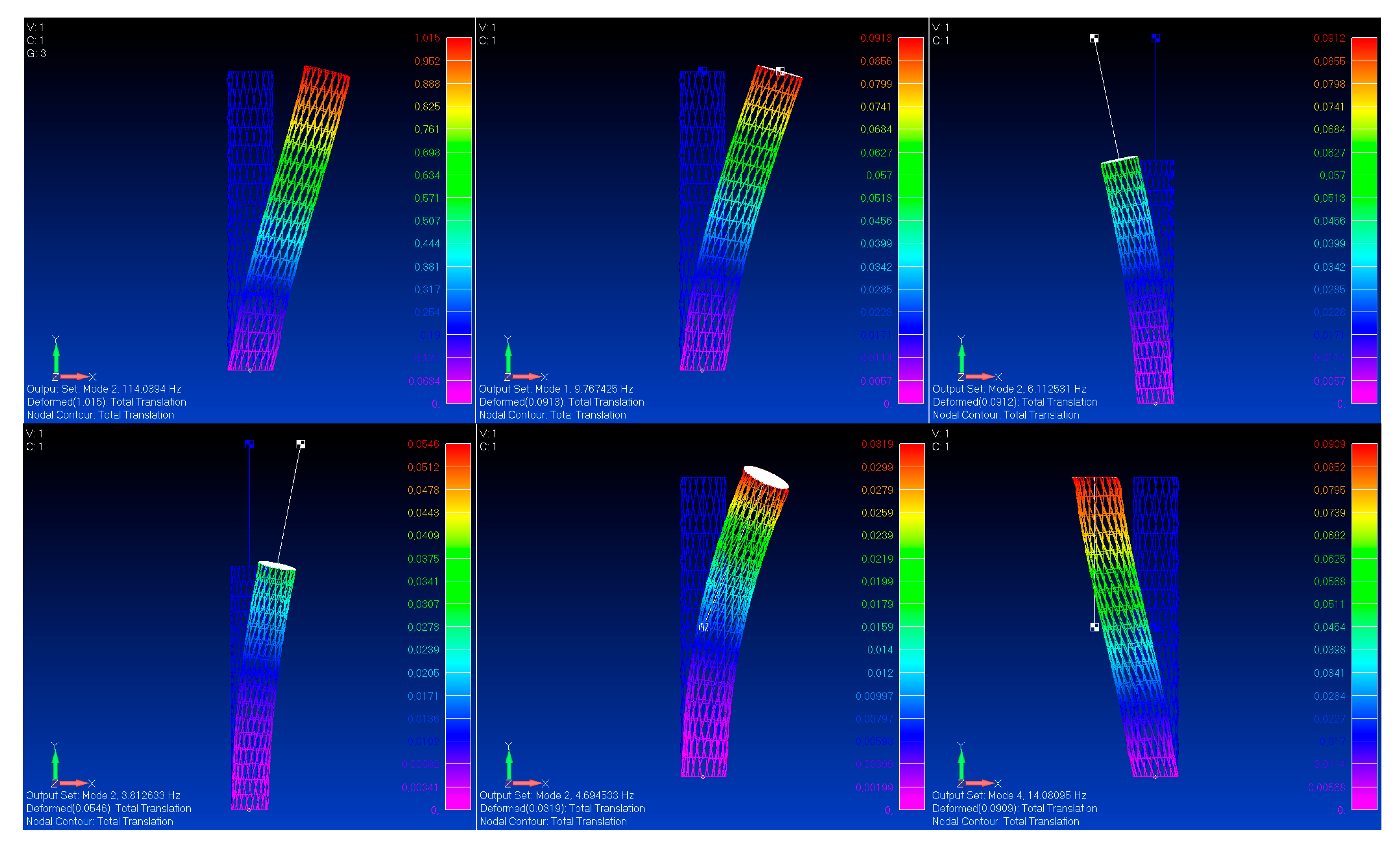
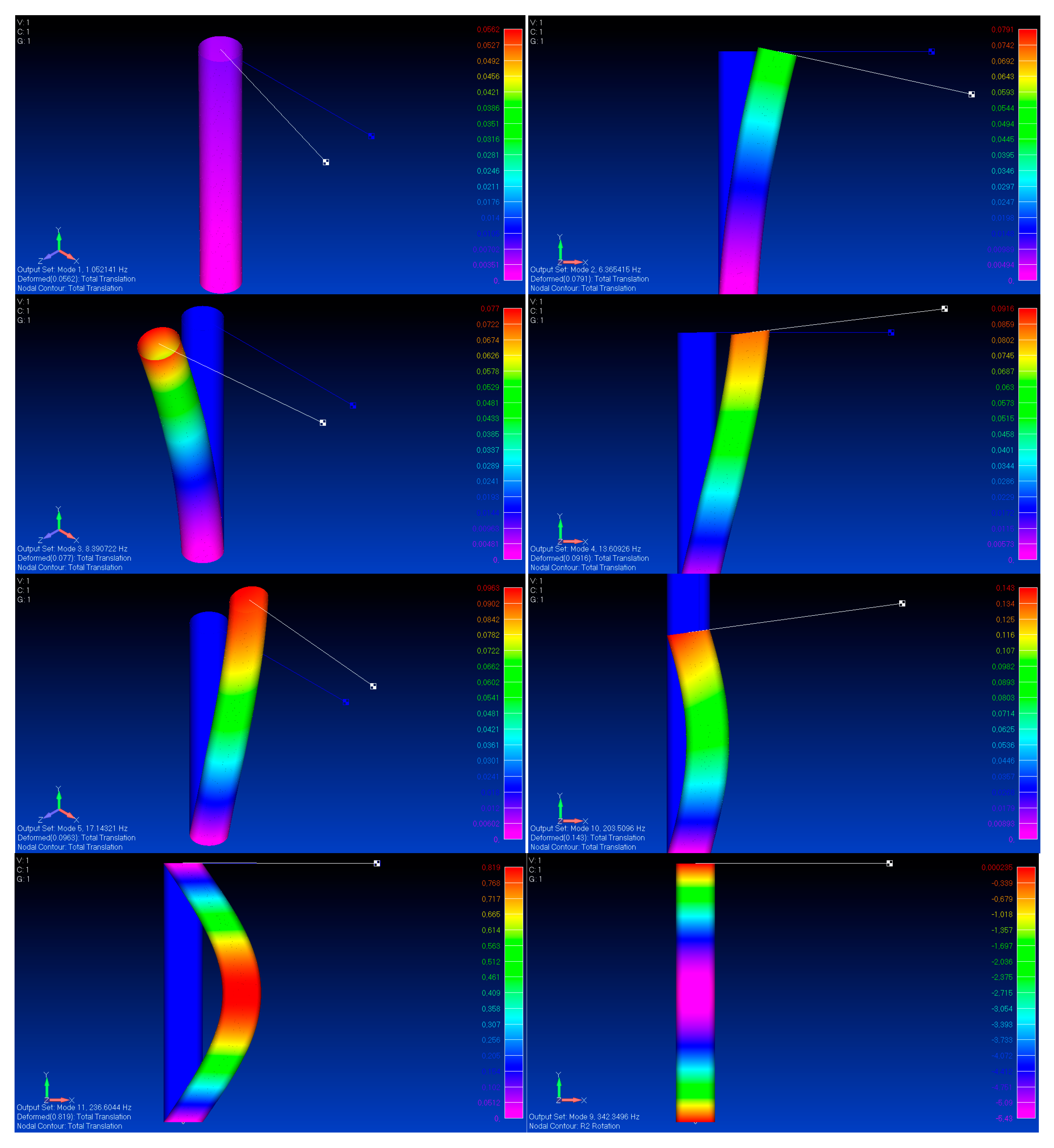
Table 4. All the identified mode shapes are shown in
Figure 4,
Figure 5 and
Figure 6.
As can be seen, the correlation between analytical and FE models is excellent. This demonstrates that an Anisogrid structure with a reasonably dense system of ribs is well simulated by the smeared counterpart, or, on the contrary, an excellent correlation is the proof that the specific Anisogrid configuration is reasonably dense. Indeed, coarser systems of ribs are expected to provide a lower performance due to the occurrence of local effects, which becomes more and more dominating. As a consequence, the smeared modelling could be no longer representative enough of the mechanical behavior. To demonstrate this fact, consider two alternative Anisogrid structures that are identical in terms of smeared elastic and mass density properties—that is, they should have the same natural frequencies—but are characterized by a less dense systems of ribs. To generate these alternative structures, it is sufficient to scale the number of hoop sections and helical ribs in order to keep the same helical angle, as per Equation (1), and to adjust the cross-section widths accordingly. Thus, starting from the solution adopted in the example, the number of hoop sections and helical ribs can be halved, that is, nse = 8, nh = 10. The spacing of hoop and helical ribs is doubled. Then, to achieve the same smeared properties, it is necessary to double the widths of ribs, that is bc = 2.0 mm and bh = 12 mm. An even coarser configuration can be obtained with nse = 4, nh = 5, bc = 4.0 mm, and bh = 24 mm.
These three configurations were already anticipated in
Figure 1. To test the effect of such different systems, consider, for example, the clamped–free beam case as a reference (
Table 2). The FE results of the baseline and the two alternative structures are reported in
Table 5. This comparison shows limited reductions in the natural frequencies for the first alternative (Freq. 1), that is, in the range of 6–12%, and rather drastic reductions for the second alternative (Freq. 2), that is, in the range of 40–55%.
3.2. Coupled Modes
To check the accuracy of the developed coupled models, first consider a CFRP shell made of a balanced symmetric laminated skin. The following lamina properties are are introduced: E
11 = 245 GPa, E
22 = 7.7 GPa, G
12 = 3.9 GPa, ν
12 = 0.24, ply thickness = 0.125 mm, and mass density ρ = 1600 kg/m
3. Without loss of generality, it is assumed that the skin is made of a simple stacking sequence including 6 plies oriented at 0° (the axis direction of the beam) and two plies oriented at 90°, that is [90/(0)
6/90]. The overall thickness of the shell is t = 1.0 mm. The corresponding stiffness and mass parameters are reported in
Table 6. These values are calculated according to Equation (54), introducing the equivalent axial modulus of elasticity, E
x, and the equivalent in-plane shear modulus, G
xy, of the laminate (see, for example, [
24]). The non-structural mass corresponds to m = 100 kg located with the transverse offset r = 1.5 m and I
x = 500 kgm
2, so that the total torsional moment of inertia about the axis of the shell is I
t = 725 kgm
2. The moments of inertia at bending are assumed to be the same in the principal directions, that is, I = I
y = 250 kgm
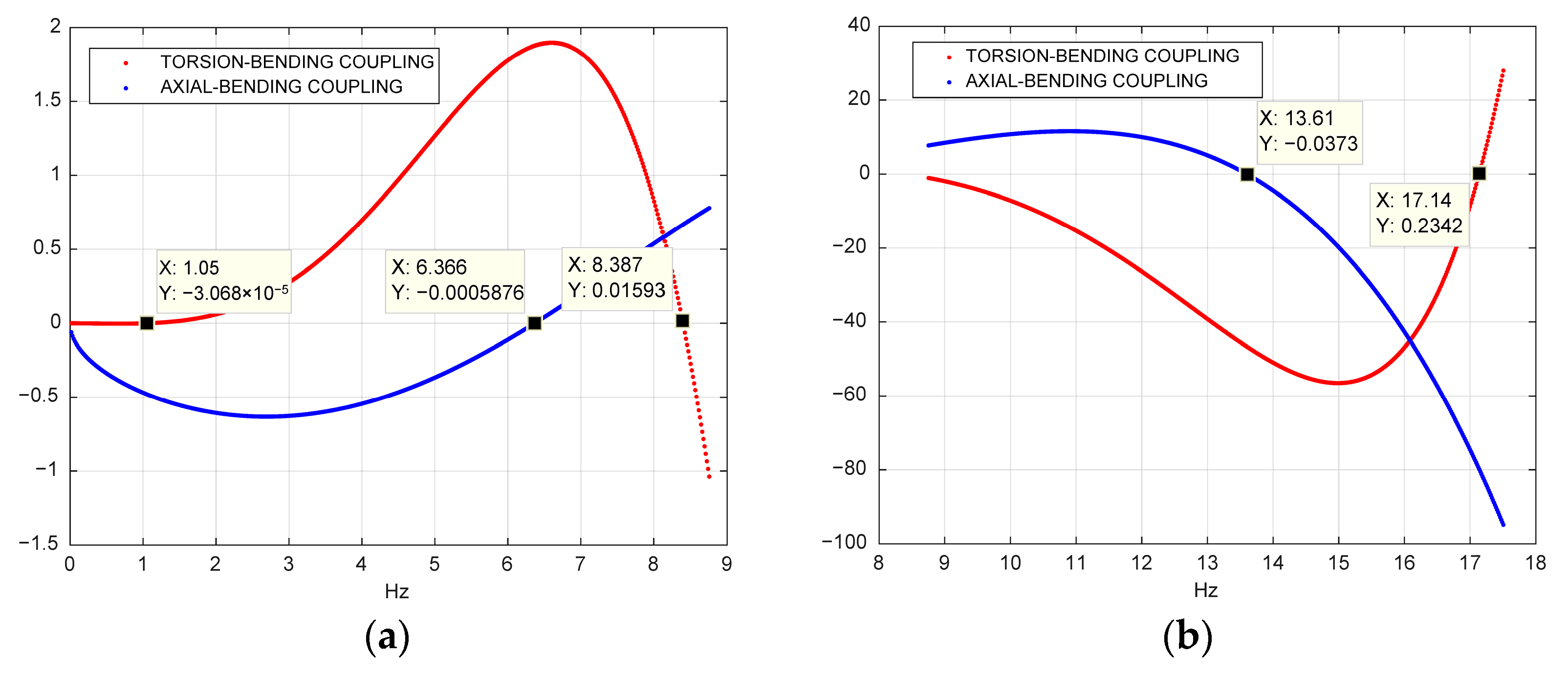
2. The coupled modes are obtained exploring the respective determinant functions, an example of which is reported in
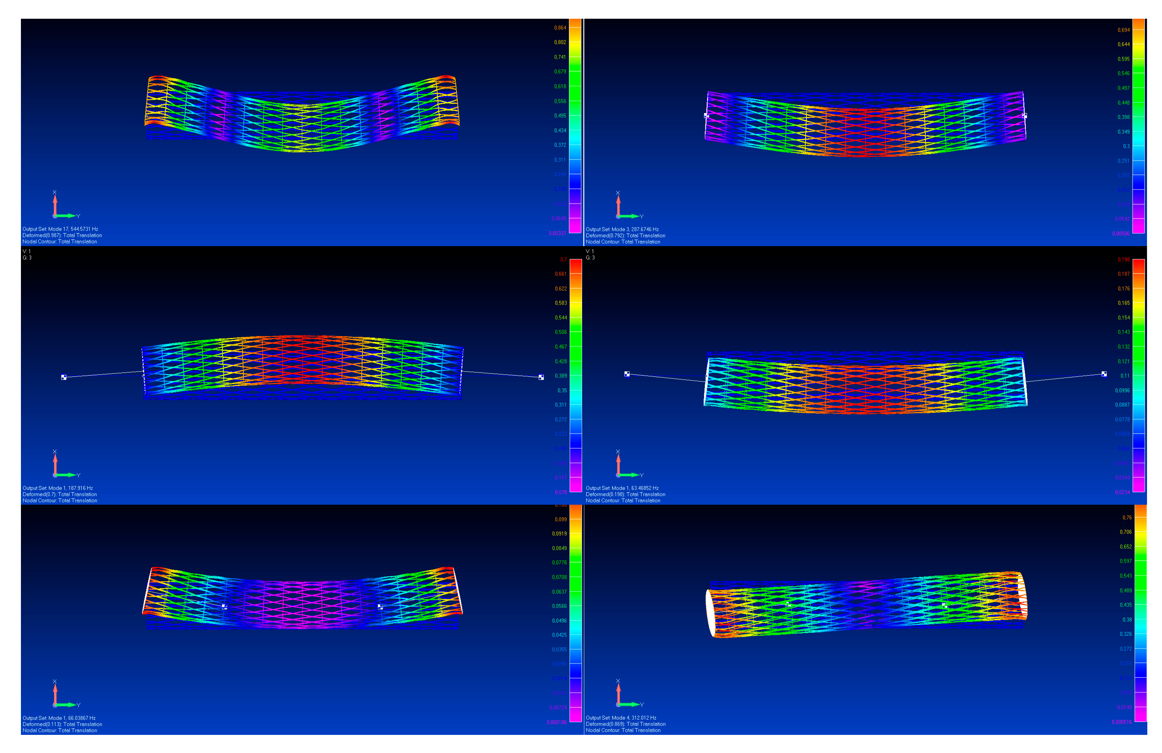
Figure 7. The coupled frequencies (the first eight modes) are compared with FE models and reported in
Table 7. The results are coincident. The coupled modes are illustrated in
Figure 8.
4. Minimum Mass Solution with a Constraint on the Fundamental Frequency
As shown in the foregoing examples, to calculate the natural frequencies of the shell-beam, it is sufficient to explore the roots of the determinant function. This approach is simple to verify or modify a certain structure that is already sized. It is less efficient when the shell-beam has to be optimized in order to reach a specific frequency requirement with the minimum mass, considering that four variables and several parameters are, in principle, involved. To this aim, an optimization routine based on a non-linear constrained minimization algorithm, referred to as “fmincon”, included in the MATLAB Optimization Toolbox, has been constructed. In this routine, the objective function is given by the mass of the shell to be minimized. An “equality constraint” corresponding to the determinant of the characteristic matrix is set equal to zero. With this approach, the natural frequencies are identified by the algorithm. The only warning is to check that the routine, which is capable of capturing local minima through the algorithm, has actually identified the lowest natural frequency. This can be performed, as earlier, by just exploring the first natural frequencies of the obtained solution. If the identified frequency is not the lowest, it is necessary to increase the lower bound of the shell thickness variable and run a new simulation.
In this example, the last simulation of the clamped–free Anisogrid beam is adopted as a reference, specifically, the case # 6 of
Table 2. As a typical design issue, assume that we want to reach the fundamental frequency of 14 Hz with the minimum structural mass. The baseline solution already exists and corresponds to the mass per unit length B
ρ = 1.51 kg/m. The point is to find out whether the mass can be reduced with a more efficient design. This means exploring other configurations by setting the number of hoop sections and changing the number of helical ribs. For each configuration that corresponds to a certain helical angle, the minimum mass solution is found by the routine acting on the remaining variables. In this case, n
se = 24 and n
h is changed between 10 and 30.
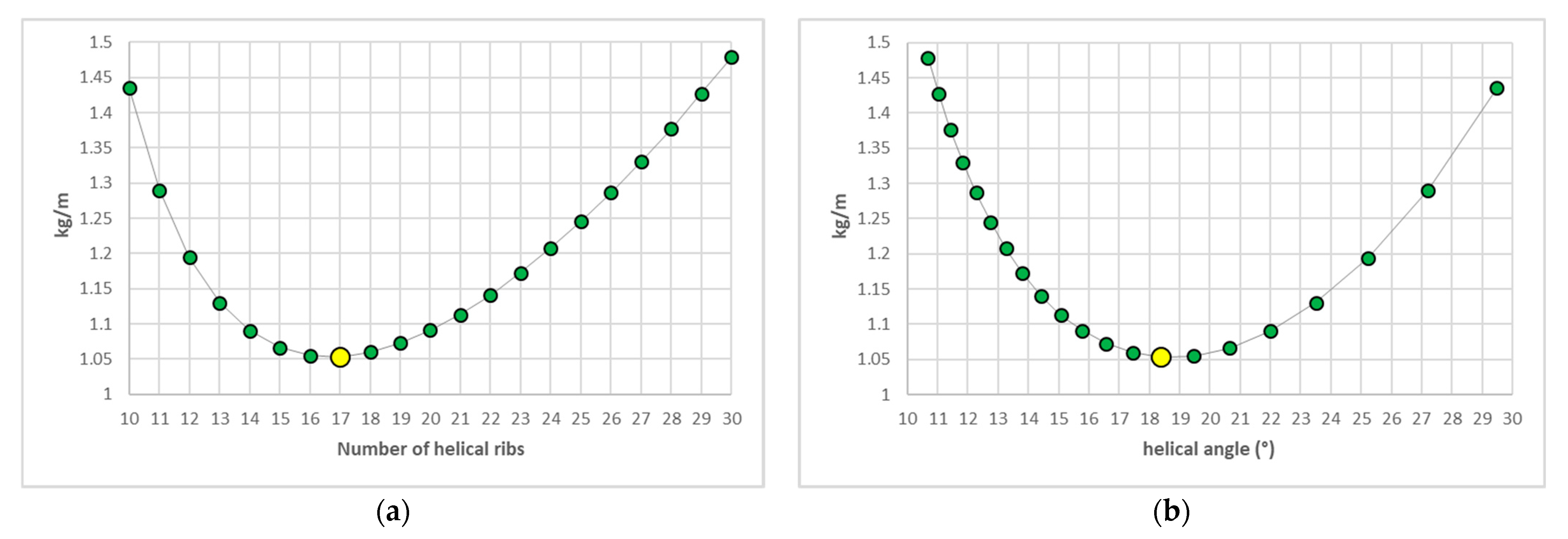
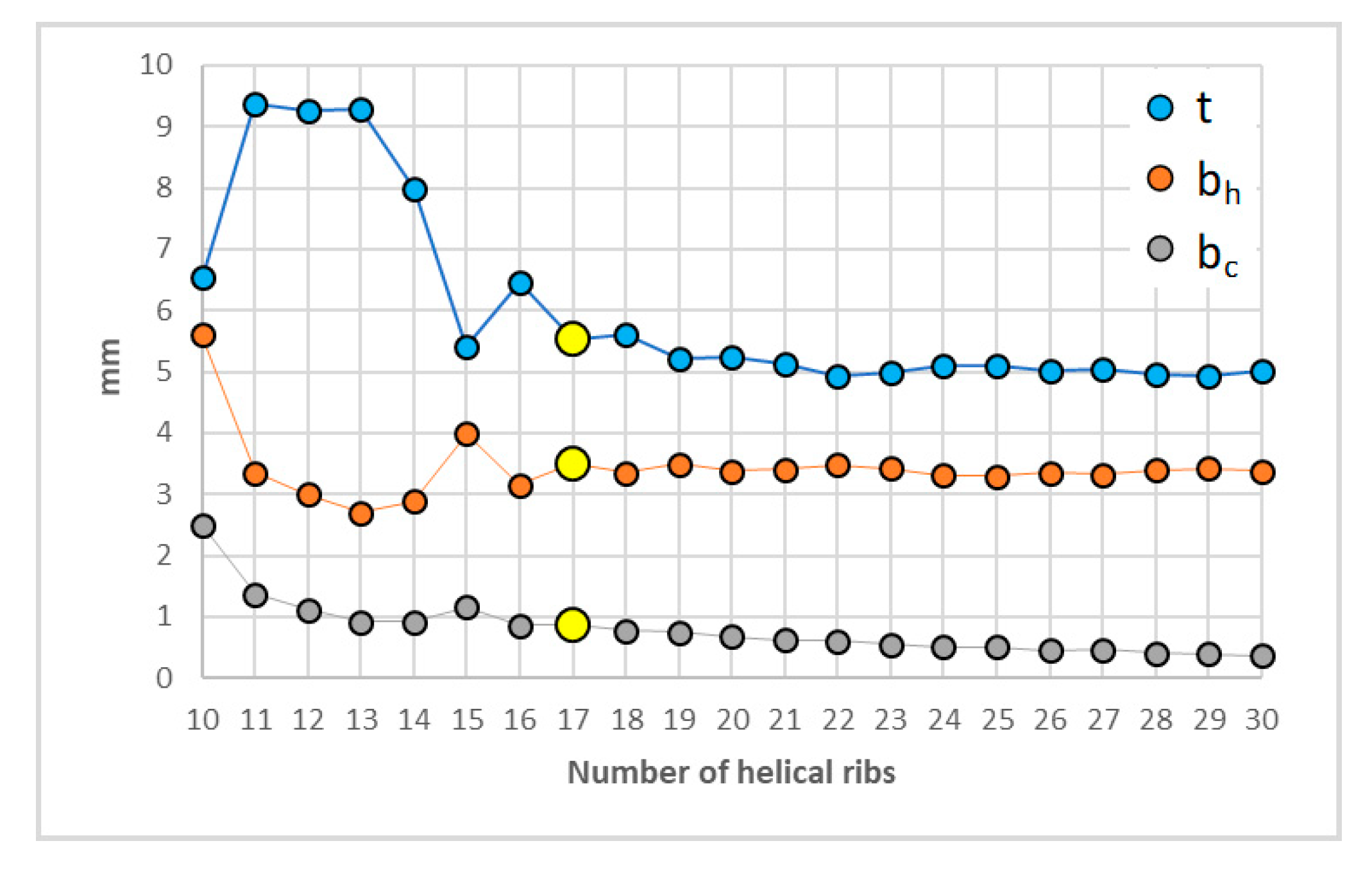
The results of the optimization routine are reported in the plots of
Figure 9 and
Figure 10, showing the minimum B
ρ against n
h and against φ, and the corresponding optimal cross-section values of the ribs. Incidentally, all these solutions are more efficient than the baseline. In particular, a minimum mass solution (yellow point) exists that corresponds to B
ρ = 1.05 kg/m and is obtained in conjunction with φ = 18.4° (n
h = 17), t = 5.5 mm, b
h = 3.5 mm, and b
c = 1.0 mm. This means that an important mass saving of 30% could be achieved in this example.
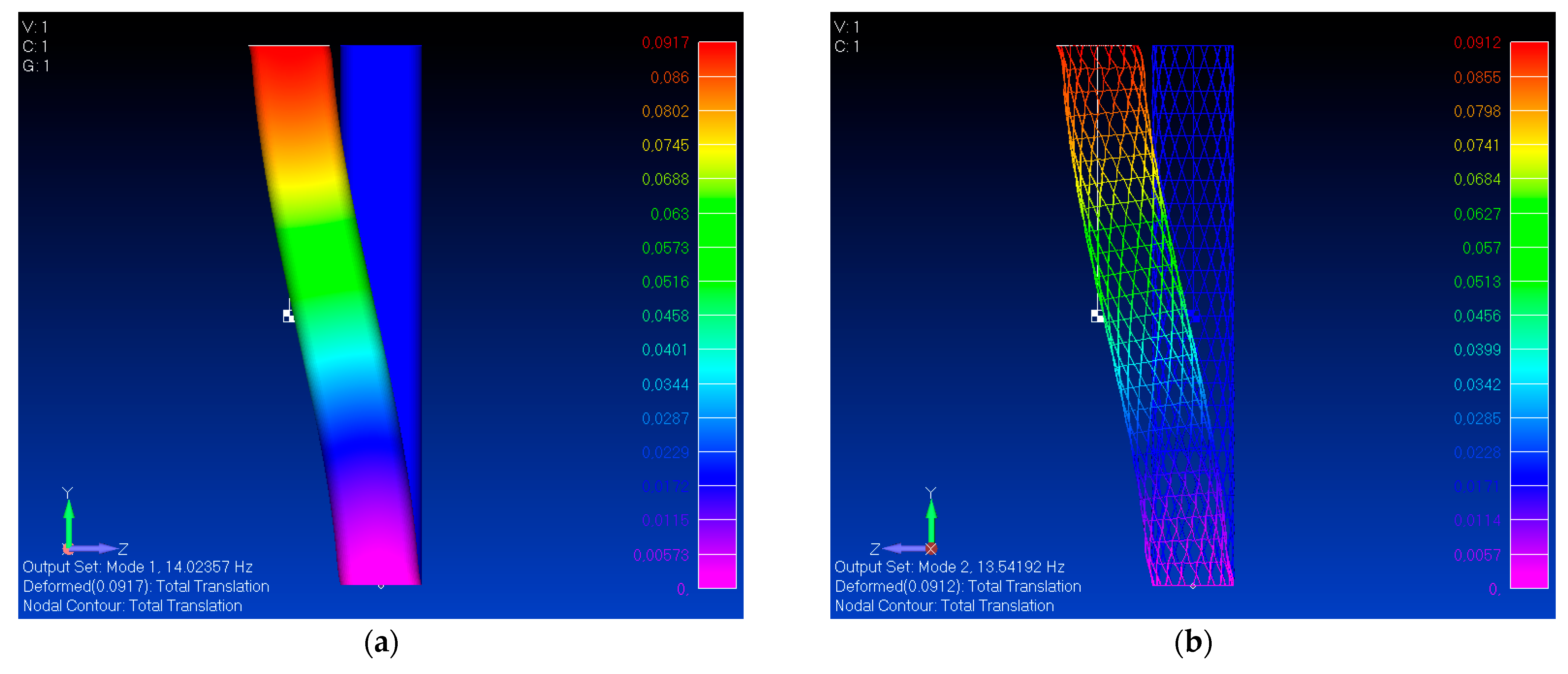
However, we presume that the frequency value addressed by the analytical smeared model is an upper bound of the actual value. To check the consistency between the Anisogrid and the smeared counterpart, the respective FE models are constructed and verified. The smeared FE model is based on 2D “shell” elements (“CQUAD4” in the nomenclature of the Nastran solver) and uses four equivalent elastic properties, similarly to a laminated orthotropic skin. As can be seen from
Figure 11, this model confirms the exact frequency value of the analytical solution, whereas the discrete FE model based on 1D elements demonstrates only a slight reduction of 3.3%, thus confirming an excellent agreement in this case.
5. Conclusions
The pure bending and the coupled axial–bending and torsional-bending natural frequencies of Anisogrid cylindrical shell-beams carrying rigid bodies at the boundaries have been investigated. The Anisogrid structure is reduced to an equivalent continuous model through smeared elastic properties and considered as any homogeneous orthotropic shell (or any symmetric balanced laminated skin) for which the correlation between the analytical models and corresponding FE models is perfect. This coherence, in a preliminary design phase, indicates that the effect of the main variables and parameters has been correctly set, which is rather encouraging in view of the detailed design, manufacturing, and test of real components.
The smeared approximation normally provides the upper bounds of the frequencies of the real discrete FE model, according to the more or less dense system of ribs. In particular, Anisogrid configurations with dense systems of ribs—usually preferred in the general design—are closer to the theoretical values.
Overall, the smeared modelling suggests the existence of ideal solutions that confirm the expected theoretical values and can be approached by the optimal design. To this aim, a simple and effective optimization method has been proposed, which helps to identify the minimum mass solution with a constraint on the fundamental frequency. In the reported example, a potential weight saving of about 30% was obtained, with respect to the initial solution, by properly changing the helical angle and the other variables.
Clearly, a similar approach for preliminary design could be applied to laminated skins, as well, adopting the same formulation and introducing the proper variables.
Finally, additional analytical models could be tailored and implemented to explore further possible residual margins of weight saving according to the specific case, for example, by considering two-beams systems separated by flanges or multi-span sections optimized in conjunction.

