Abstract
Marine noise pollution is a significant threat to global marine ecosystems and human activities. Most underwater sound-absorbing materials operate in the mid-to high-frequency bands (typically 1–10 kHz for mid-frequency and above 10 kHz for high-frequency), and current underwater low-frequency sound absorption performance remains unsatisfactory, with large structural sizes. To address these issues, a novel metasurface composed of a hexagonal Helmholtz resonator structure made of rubber and metal, combined with an embedded rough neck, is proposed. By introducing roughness into the neck of the Helmholtz resonator, this structure effectively provides the necessary acoustic impedance for low-frequency sound absorption without changing the overall size, thus lowering the resonance frequency. The finite element method is used for simulation, and theoretical validation is performed. The results show that the Helmholtz resonator with the rough neck achieves near-perfect acoustic absorption at a deep subwavelength scale at 81 Hz. At the absorption peak, the wavelength of the sound wave is 370 times the thickness of the resonator. By coupling seven absorption units and optimizing the parameters using a genetic algorithm, the metasurface achieves an average absorption coefficient greater than 0.9 in the 60 Hz to 260 Hz range. The complementary sound absorption coefficients of the unit cells at different frequency bands effectively broaden the absorption bandwidth.
1. Introduction
Underwater acoustic materials are essential for achieving acoustic stealth and enhancing sonar detection capabilities in underwater vehicles such as submarines [1]. Scattered sonar waves can be absorbed, reducing the likelihood of detection, while transducer performance can be optimized to improve the efficiency of acoustic wave transmission and reception, thereby supporting deep-sea concealment and accurate detection [2]. Due to their longer wavelengths and lower propagation losses, underwater sound waves are significantly more difficult to control than airborne sound waves at the same frequency [3]. The design and performance prediction of underwater acoustic metamaterials present more complex challenges [4,5,6]. In recent years, the field of acoustic metamaterials has undergone rapid development, with numerous underwater variants emerging continuously. To achieve lighter and thinner acoustic materials, increasing attention has been directed toward the use of metasurfaces for sound manipulation. Metasurfaces, a type of acoustic metamaterial with subwavelength thickness, offer a compact and efficient solution for acoustic wave manipulation. Metasurfaces are generally classified into reflective, absorptive, and transmissive types [7,8,9]. Among these, absorptive metasurfaces—commonly used in noise reduction—can be further categorized into membrane-type and cavity-type structures. However, membrane-type metasurfaces exhibit several limitations, primarily relying on membrane vibration for sound absorption, which necessitates uniform and controllable tension, thereby imposing high manufacturing constraints. Additionally, they tend to have short operational lifespans and narrow absorption bandwidths, which limit their effectiveness in practical applications.
Due to the limitations of membrane-type metasurfaces, cavity-type metasurfaces have increasingly attracted researchers’ attention [10]. These structures primarily operate based on strong resonance and viscous friction within cavities, enabling simpler fabrication and improved durability. Hu et al. derived an analytical expression that can theoretically model the sound absorption effect and concluded that when the cavity size is much smaller than the wavelength, folding the cavity does not affect the absorption performance [11,12]. The folded cavity structure they designed had a thickness of only 7/100 of the central frequency wavelength. In 2017, Yang et al. optimized the absorptive metasurface unit based on causality constraints, achieving quasi-perfect sound absorption above 400 Hz, with a structural thickness less than one-seventh of the wavelength [13]. Song et al. demonstrated a liquid-metal metasurface enabling 51.1% central-frequency shift and wide-angle absorption (up to 60°) via microfluidics, offering a versatile platform for terahertz shielding and stealth applications [14]. In 2018, Long et al. designed a labyrinthine structure based on dual-channel Mie resonances [15]. This metasurface could achieve multi-order sound absorption with nearly equal peak values, the lowest of which reached 0.952. The ratio of the corresponding wavelength to the structural thickness was 30.6. In 2020, Duan et al. introduced surface roughness in the neck of embedded Helmholtz resonators to tune the acoustic impedance, resulting in a 16.0% downward shift in the absorption peak frequency and a 19.6% increase in peak absorption [16]. In 2021, Duan et al. further developed a multilayer Helmholtz resonator-based acoustic metamaterial that could absorb multiple sets of noise at specific frequencies by adjusting the structural parameters of the resonators [17]. In 2022, Zhang et al. proposed a fully rough-neck embedded Helmholtz resonator. By tailoring the wall geometry of the embedded neck, they enhanced low-frequency absorption [18]. The results showed that when both axial and radial roughness were present in the neck, acoustic energy dissipation increased not only within the neck but also inside the cavity. In 2023, Li et al. experimentally demonstrated a graphene-based absorbing metasurface that enables independent, dynamic tuning of the reflection amplitude in one polarization and the resonance frequency in the orthogonal polarization, offering a new degree of freedom for tunable microwave metasurfaces with potential applications in communications, wireless transmission, and sensing [19]. In 2024, Zoe introduced an acoustic metasurface composed of rough-necked and non-uniformly sliced substructures, achieving both low-frequency narrowband and broadband absorption. This provided a viable solution for the development of ultrathin low-frequency noise barrier [20]. In 2025, Li et al. developed a 3MSPR device combining MXene-enhanced metasurface biosensors with microfluidics for real-time, multifunctional antibody monitoring, boosting label-free IgG detection sensitivity over 250-fold to a 2.56 ng/mL detection limit, with potential in precision diagnostics, drug development, and bioprocess monitoring [21].
Although extensive optimization and structural innovation have been conducted on Helmholtz resonators—significantly enhancing their acoustic performance—a critical limitation remains: their resonant frequency is strongly dependent on the geometric parameters of the cavity and neck. In practical underwater applications such as sonar detection and submarine anechoic tile design, achieving low-frequency sound absorption and noise reduction typically requires increasing the cavity volume or neck length of the resonator. However, underwater equipment is typically subject to stringent spatial constraints. For instance, the interior of a submarine must accommodate the installation of various equipment and allow for crew movement, while maintaining hydrodynamic performance. These constraints make it highly impractical to lower the absorption frequency solely by increasing the physical dimensions of Helmholtz resonators. Consequently, achieving low-frequency sound absorption and noise mitigation remains a significant challenge in underwater environments.
In this study, the foundational structure consisted of a Helmholtz resonator with a rubber lining cavity and an embedded roughened neck. Surface roughness was incorporated into the neck of the resonator. The inner wall of the resonant cavity was coated with rubber, which, due to its elasticity and damping characteristics, facilitated Helmholtz resonance by providing acoustic compliance and energy dissipation. The embedded roughened neck contributed to the acoustic mass and impedance, thereby lowering the resonant frequency. The resonator’s behavior was analyzed using a combination of analytical and numerical methods. The influence of varying roughness parameters in the neck tube on sound absorption performance was examined in detail, including an analysis of how each parameter affected the reduction in peak absorption frequency and improvement in absorption efficiency. To achieve broadband low-frequency absorption, multiple rough-neck Helmholtz resonator units were arranged in parallel to construct a metamaterial surface. By integrating a genetic algorithm with the finite element method (FEM), the sound absorption coefficient was computed using FEM, while the genetic algorithm was utilized to optimize performance across the complex structural parameter space.
2. Materials and Methods
2.1. Theoretical Model
The cavity of the Helmholtz resonator consists of a rubber lining and a water-filled chamber. In the rough-neck Helmholtz resonator, both the bottom surface of the cavity and the inner wall of the embedded neck are assumed to be acoustically rigid. According to the electro-acoustic analogy method, the acoustic impedance of the water chamber and that of the rubber lining are in a parallel relationship. Therefore, the total acoustic impedance of the resonator cavity can be expressed as
Because the wavelength of low-frequency sound waves is relatively long, the sound pressure within the water chamber can be assumed to be approximately uniform. Under this condition, the compression vibration of the rubber lining is also spatially uniform. Given that wave propagation in rubber is predominantly longitudinal, the acoustic impedance of the rubber lining can be expressed as
where is the volume velocity of the rubber, is the density of the rubber, is the longitudinal wave speed, is the sound pressure, is the imaginary unit, and is the angular frequency. is the volume of the rubber, where is the cross-sectional area of the hexagonal cavity. Similarly, the acoustic impedance of the water cavity can be expressed as
where and are the density and sound speed of water, respectively. is the volume of the water cavity after subtracting the rough-neck region, and is approximately the cross-sectional area of the embedded neck.
The inner wall of the embedded rough neck follows an idealized cosine curve, with its radius varying periodically along the x-axis. The function can be expressed as [22,23,24]
where is the coordinate along the axial direction of the embedded rough neck, is the relative roughness, which quantifies the amplitude of the cosine-shaped roughness. is the wavenumber of the cosine-shaped roughness in the axial direction. The curvature of the rough neck with axial cosine roughness can be expressed as [25]
where is the modified Bessel function of the first kind of order n. When the relative roughness , the curvature corresponds to that of a smooth neck tube.
According to the model proposed by Pride et al. [25], the acoustic impedance of the rough neck can be expressed as
where is the kinematic viscosity, is the dynamic viscosity in still air, is the viscous permeability, is the static flow resistivity of the rough neck tube, is the viscous characteristic length, and is the torsion ratio for an axisymmetric neck. Considering the end effect of the rough neck on the acoustic mass and resistance, should be modified as [26]
where is the ratio of the end radius of the rough neck to the thickness of the viscous boundary layer, and is the end diameter of the rough neck.
Therefore, the surface acoustic impedance of the embedded rough-neck Helmholtz resonator absorption unit can be expressed as
In the experiment, to simplify the analysis, it is assumed that the backing condition of the metasurface is rigid. Therefore, the sound absorption coefficient of the metasurface with embedded rough-neck resonators can be calculated using the following formula.
where R is the reflection coefficient, and is the surface acoustic impedance of the absorption unit.
2.2. Finite Element Simulation
The overall structure of the rough-neck Helmholtz resonator absorption unit comprises three primary components: a rough neck embedded in the back cavity of the resonator, a rubber lining, and a metal shell that defines the cavity. These components are interconnected through a top linking aperture. Figure 1a,b illustrate the structural comparison and dimensional parameters of the rough-neck tube and its smooth-neck counterpart, respectively.
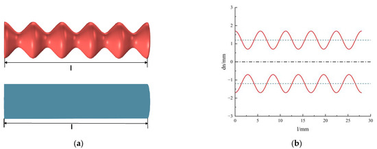
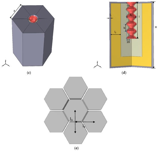
Figure 1.
(a) Comparison between the rough-neck tube and the smooth-neck tube; (b) comparison of the rough and smooth-neck tubes in a Cartesian coordinate system; (c) embedded rough-neck Helmholtz resonator absorption unit; (d) cross-sectional view of a unit cell; (e) the horizontal and vertical distances of the unit cell with respect to its neighboring unit cells.
Figure 1c,d illustrate the schematic diagram and cross-sectional view, respectively, of the designed low-frequency sound-absorbing unit composed of a rubber lining and an embedded roughened neck. In the geometry, denotes the side length of the regular hexagonal Helmholtz resonator, H is the cavity height, is the thickness of the panel, and is the thickness of the rubber lining. is the average diameter of the embedded rough neck, is the length of the embedded rough neck, is the wavelength of the roughness on the embedded neck, is the amplitude of the embedded rough neck, and is the wall thickness of the embedded rough neck. The detailed geometric parameters used in this study are listed in Table 1.

Table 1.
Geometric parameters of the embedded rough-neck Helmholtz resonator (unit: mm).
To validate the sound absorption performance predicted by the theoretical model, a numerical model was developed in COMSOL Multiphysics 6.2 using the finite element method (FEM) [27,28,29]. COMSOL Multiphysics offers powerful multiphysics coupling, a user-friendly graphical interface, modular extensibility, CAD 2021 integration, and MATLAB 2021a compatibility, making it highly suitable for complex acoustic–structure interaction simulations. Its main limitations include high computational resource requirements for large-scale models, a learning curve for advanced features compared to other FEA software. For a clearer comparison with other simulation tools, please refer to Table 2 for details [30,31]. Considering the periodic arrangement of unit cells within the metasurface, the simulation was conducted on a single absorption unit. To incorporate thermoviscous losses and improve the accuracy of the results, a multiphysics coupling approach was adopted. Specifically, the pressure acoustics module, solid mechanics module, and thermoviscous Acoustics Module were employed to simulate the incident sound field, the rubber domain, and the water domain, respectively. The corresponding finite element model is illustrated in Figure 2. Given the significantly higher acoustic impedance of the steel outer structure compared to water, the inner wall of the rough neck embedded in the back cavity was treated as acoustically rigid in the thermoviscous Acoustics Module. The water–steel interface was modeled as a hard acoustic boundary. A background acoustic field was applied at the top surface of the model, where a normally incident plane wave with an amplitude of 1 Pa was used to simulate underwater acoustic excitation. To emulate an infinite water domain, three pairs of periodic continuity boundary conditions were imposed on the lateral surfaces of the background field. In the calculation of oblique wave incidence, the incident angle θ was set in COMSOL within the range of 0–90° and . By assigning arbitrary values of θ in this range, the direction of the incident plane wave can be flexibly controlled. The periodic boundary condition was modified to the Floquet periodicity type, which ensures the correct phase relationship of the acoustic field across unit cell boundaries and thereby satisfies the requirements for simulating oblique incidence. For mesh generation, free tetrahedral elements were applied throughout the entire model. The frequency–domain study was performed in the range of 0–200 Hz, with a frequency step size of 1 Hz.

Table 2.
Comparison of COMSOL Multiphysics with other common FEA software.
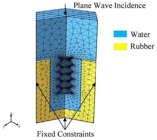
Figure 2.
Finite element model setup of the absorption unit. The blue region and the light yellow region represent water and rubber, respectively.
3. Results and Discussion
3.1. Acoustic Properties of the Metasurface
The sound absorption coefficients of Helmholtz resonators with smooth and rough-neck tubes were calculated using finite element simulation software COMSOL Multiphysics 6.2, and the results are shown in Figure 3a. The Helmholtz resonator with a smooth neck exhibited a peak absorption coefficient of 0.86 at 121 Hz. In contrast, the resonator with a rough neck achieved a peak absorption coefficient of 0.99 at 81 Hz. The resonance frequency shifted from 121 Hz to 81 Hz, corresponding to a reduction of approximately 33%. At the absorption peak, the wavelength of the incident sound wave was about 370 times larger than the total size of the absorption unit, indicating that near-perfect absorption was achieved at a deep subwavelength thickness.
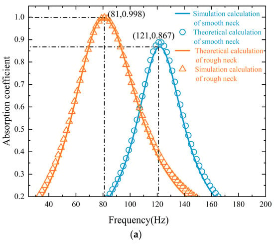
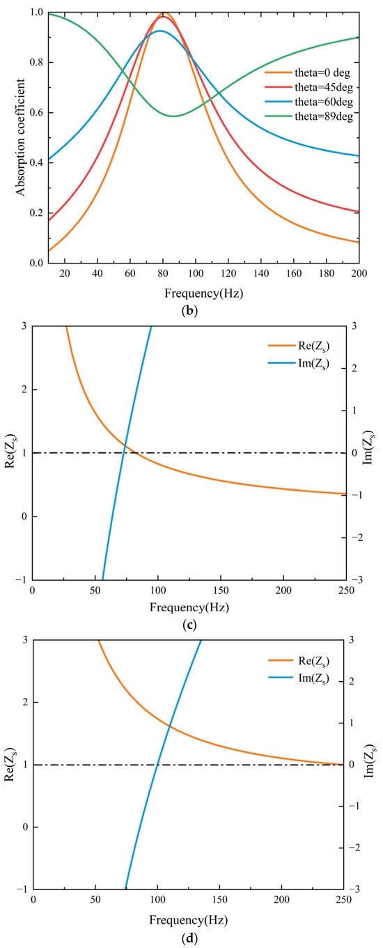
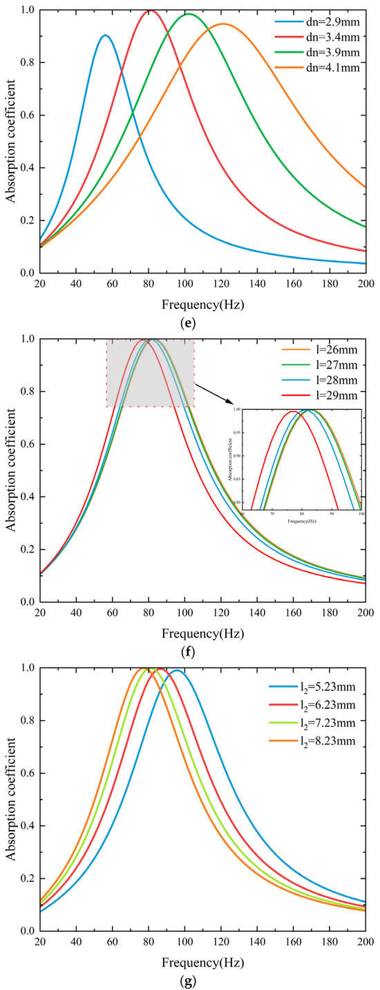
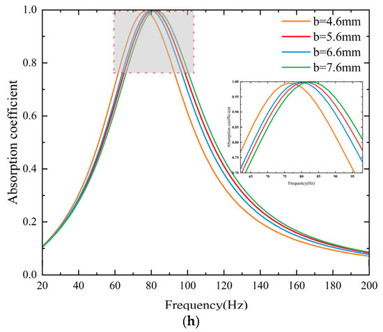
Figure 3.
(a) Comparison of theoretical and simulated sound absorption coefficients for the two structures. (b) Influence of varying incident angles on the sound absorption coefficient. (c) Surface acoustic impedance of the resonator with a rough neck. (d) Influence of average diameter on the sound absorption coefficient. (e) Surface acoustic impedance of the resonator with a smooth neck. (f) Influence of rough neck length on the sound absorption coefficient. (g) Influence of rubber lining thickness on the sound absorption coefficient. (h) Influence of roughness wavelength on the sound absorption coefficient.
In practical underwater environments, incident sound waves rarely remain strictly normal to the surface but instead arrive from various directions. Consequently, absorbers optimized solely for normal incidence may exhibit limited applicability. Examining oblique incidence is therefore essential, as it allows for a comprehensive assessment of the material’s angular stability and effectiveness, while also elucidating how incidence angle influences interfacial acoustic impedance and resonance-based absorption mechanisms. These insights provide a solid theoretical basis and design guidance for the development of underwater acoustic metamaterials with broadband and wide-angle absorption, as well as potential directional control functionalities. Figure 3b presents the absorption coefficients of the proposed structure under different incident angles. As the incident angle increases from 0° to 60°, the absorption peak consistently remains around 81 Hz, indicating that the resonant frequency is nearly independent of the incidence direction and thus exhibits good angular stability. Nevertheless, the maximum absorption coefficient gradually decreases with increasing angle, which can be attributed to the weakened coupling between the incident wave and the structure. At an extreme grazing incidence (θ = 89°), the absorption spectrum evolves from a sharp single peak into a relatively broad distribution, while maintaining high absorption in both low- and high-frequency regions, thereby revealing a certain degree of broadband absorption capability. These findings demonstrate that the proposed structure not only enables efficient low-frequency sound absorption but also maintains strong robustness against variations in the incidence angle, ensuring reliable performance in complex acoustic environments.
According to Equation (9), perfect sound absorption () is achieved when the real part of the acoustic resistance satisfies , and acoustic reactance satisfies , that is, when . As shown in Figure 3c,d, the acoustic resistance of both the smooth neck and rough neck approaches 1 at the resonance point, while the acoustic reactance approaches 0.
However, due to the inherent coupling between acoustic resistance and reactance, it is generally difficult to independently and precisely tune them. A more in-depth analysis of the resonance mechanism reveals that the resonance frequency of the low-frequency absorption unit is primarily determined by the acoustic resistance, while the absorption coefficient is governed by the acoustic reactance. Within the resonance region, the acoustic reactance varies significantly with frequency, whereas the acoustic resistance remains relatively stable and less sensitive to frequency changes. Minor discrepancies between the simulation and theoretical results may arise from several factors, such as the assumption of a rigid backing condition in the theoretical model or insufficient boundary layer mesh resolution in the simulation of the rough-neck geometry.
To further investigate the influence of geometric parameters on the sound absorption performance while keeping the external structure unchanged, a series of numerical simulations was conducted. The parameters studied include the average diameter of the embedded rough neck, the length of the rough neck, the wavelength of the roughness pattern, and the thickness of the rubber lining. Simulations were performed over a frequency range of 20–200 Hz using selected materials. Optimal structural dimensions were identified within this range to achieve superior low-frequency underwater sound absorption.
As shown in Figure 3e, an increase in the average diameter of the rough neck reduces the acoustic mass per unit length of the neck, resulting in a shift of the absorption peak toward higher frequencies. When increases from 2.9 mm to 4.1 mm, the corresponding peak frequency rises from 56 Hz to 122 Hz.
According to , where is inversely proportional to the relative roughness , an increase in leads to a decrease in relative roughness, resulting in a rise in the resonance frequency. This result also demonstrates that transitioning from a smooth to a rough neck can enable ultra-low-frequency sound absorption. Moreover, changes in the average diameter of the rough neck affect the half-power bandwidth of the absorption peak. An increase in diameter enhances viscous losses within the neck, thereby broadening the frequency range over which energy dissipation occurs. Conversely, reducing the diameter may narrow the bandwidth.
As shown in Figure 3f, when the neck length increases from 26 mm to 29 mm, the peak absorption frequency shifts from 84 Hz to 78 Hz. Although the increase in enhances the acoustic resistance and promotes energy dissipation, the overall variation is relatively small. Near-perfect absorption can still be achieved without significantly modifying the neck length.
Figure 3g shows that increasing the rubber lining thickness leads to a larger rubber volume and thus greater acoustic compliance. This results in a downward shift in the absorption peak frequency. When increases from 5.23 mm to 8.23 mm, the peak frequency drops from 96 Hz to 78 Hz. A properly tuned rubber lining can match the surface acoustic impedance of the resonator more closely to the characteristic impedance of water, enabling a higher peak absorption coefficient. When the impedance matching condition is satisfied—i.e., the acoustic resistance approaches 1 and the acoustic reactance approaches 0—the absorption coefficient can exceed 99%.
As shown in Figure 3h, when the roughness wavelength increases from 4.6 mm to 7.6 mm, the corresponding peak frequency rises from 76 Hz to 82 Hz—an increase of only 7%. According to , with fixed, increasing reduces the wavenumber of the cosine-shaped roughness. However, the shift in the absorption coefficient peak caused by changes in is not as pronounced as that induced by changes in the relative roughness . In summary, the average diameter of the rough neck must be optimized in coordination with other parameters such as the rubber layer thickness and the wavelength of the rough neck in order to achieve a peak absorption at the target frequency.
Matching the acoustic impedance with that of the surrounding medium allows sound waves to fully enter the absorption unit without reflection. For an absorption unit, impedance matching is a key condition for achieving good sound absorption performance. However, in order to achieve a high absorption coefficient, it is also necessary to have sufficient capability to dissipate acoustic energy. To further investigate the working mechanism of the absorption unit, the sound pressure distribution and power dissipation density within the unit were plotted, as shown in Figure 4.
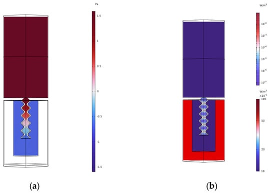
Figure 4.
(a) Acoustic pressure distribution within the absorption unit, extracted from the central cross-sectional plane. (b) Energy dissipation density within the absorption unit, extracted from the central cross-sectional plane. The upper region represents the surrounding water domain, the outer wall is composed of rubber material, and the inner cavity is filled with water.
As shown in Figure 4a, the sound pressure at both the upper and lower ends of the embedded neck is continuous, with a noticeable gradient in sound pressure. This indicates a pressure drop between the incident acoustic field region and the internal cavity, resulting in a phase difference between them. This phase difference is a key factor in the cancellation of the incident and reflected sound waves. In the water region inside the cavity, the sound pressure is uniformly distributed due to the relatively long wavelength of low-frequency sound waves. Figure 4b shows the dissipation distribution within the cavity. After the sound waves enter the cavity, the rubber coating undergoes compressive vibrations driven by the incident waves, which is one of the main sources of energy dissipation. Additionally, the highlighted areas are concentrated around the embedded neck, indicating that another major source of energy loss comes from the viscous and thermal losses in the embedded neck region.
3.2. Multi-Unit Parallel Configuration and Optimization Method
To achieve enhanced sound absorption performance, seven low-frequency absorbing units with different diameters are arranged periodically to form a low-frequency broadband acoustic metasurface. The unit structure maintains a deep subwavelength thickness, and the cavity height of all seven units is kept uniform at , while the aperture parameters of the internal cavities are adjustable. Due to the variation in structural parameters, each unit exhibits a distinct resonant frequency. When combined in parallel, these units produce multiple overlapping absorption peaks, enabling continuous broadband absorption over a wider frequency range. The geometric model of the metasurface is shown in Figure 5. The normalized surface acoustic impedance of the parallel structure can be expressed as
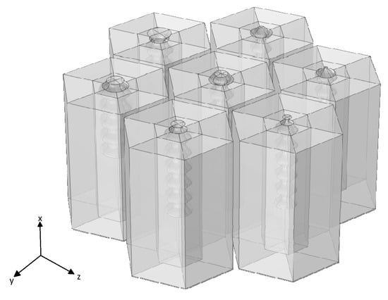
Figure 5.
Broadband coupling model of low-frequency sound absorbing units.
The variation of has a particularly significant effect on the sound absorption coefficient. To achieve a balance between excellent low-frequency absorption and broadband performance, a genetic algorithm (GA) was employed to globally optimize the parameters of the metamaterial surface [32,33,34]. GA is an optimization algorithm that mimics natural selection and genetic mechanisms, and is widely used to solve complex search and optimization problems. The algorithm flowchart is shown in Figure 6a.
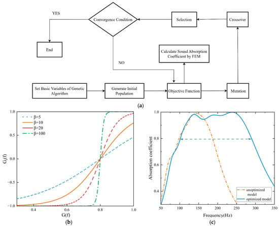
Figure 6.
(a) Optimization process of the embedded rough neck diameter ; (b) curves of the function under different values when ; (c) sound absorption coefficient curves before and after optimization.
The optimization objective was set as the average sound absorption coefficient over the target frequency band. A suitable penalty mechanism was introduced to calculate the objective function based on the absorption coefficients. A frequency-dependent function was designed using a unit step function, which transforms a sigmoid function and scales it to the range of [−1, 1], with its steepness controlled by the slope parameter . As shown in Figure 6b, When , the function curve is close to linear, and the penalty is weak. When , the curve flattens, and the optimization results show limited improvement in the low-frequency bandwidth. When and , the curve becomes steep, requiring a significant increase in the penalty. At the same time, the performance in the high-frequency range is preserved. When , the curve approaches a step function, resulting in faster convergence to low-frequency issues during early iterations, but potentially leading to local optima. The specific optimization objective function is defined as follows:
In this case, , , and is the sound absorption coefficient corresponding to the frequency . is the absorption coefficient defined by the optimization target. is the penalty function controlled by the adjustment parameter , which adjusts the steepness of the function to achieve the maximum feasible value for the sound absorption coefficient. In this optimization process, , , the frequency range is from 0 to 350 Hz, with a step size of 1 Hz. The population size of the genetic algorithm is set to 13, the number of generations is 20, the crossover method is uniform random crossover, and the mutation probability is 0.2. The detailed parameters and their descriptions for Equations (1)–(12) can be found in the Supplementary Materials.
The genetic algorithm is combined with the finite element method to simulate and calculate the sound absorption performance of each design. FEM allows for the precise calculation of the sound absorption coefficient of the metasurface, while the GA adjusts the design parameters to identify the optimal combination. To avoid excessive computational load and long processing times, the thermoviscous acoustics module in the FEM simulation can be replaced with a narrow-region acoustics module, which shortens the calculation time while ensuring accuracy. The population evolution of the genetic algorithm converged at the 13th generation, with the optimal individual from this generation selected as the reference solution. Figure 6c illustrates the comparison of the absorption coefficients before and after optimization of the metamaterial surface model, while Table 3 presents the optimization results for the average diameters of the metamaterial units. As shown, the optimized model achieves high sound absorption in the low-frequency range while simultaneously improving absorption at higher frequencies. The seven unit cells possess distinct geometric parameters, each influencing structural vibrations and wave conversion efficiency, which in turn affects the absorption coefficient. Prior to optimization, the model maintained absorption coefficients above 0.8 only within the 99–185 Hz range. After optimization, the absorption coefficient exceeds 0.8 across a broader frequency band from 102 Hz to 290 Hz, with an average coefficient above 0.93. Notably, in the range of 227–249 Hz, the absorption coefficient approaches 1, indicating near-perfect absorption. Compared to the pre-optimization model, the bandwidth with absorption coefficients above 0.8 increased by 118%. The optimized coupled multi-unit structure demonstrates superior acoustic absorption performance across both low and broad frequency ranges underwater, validating the effectiveness and applicability of the genetic algorithm in enhancing the acoustic characteristics of the structure.

Table 3.
Optimized average diameters of the metasurface structure (unit: mm).
For clarity, we reviewed the related literature and compared it with the model proposed in this study. The comparison is summarized in Table 4.

Table 4.
Comparison of key characteristics among three acoustic absorption structures.
4. Conclusions
This paper proposes a metasurface composed of a hexagonal Helmholtz resonator structure made of rubber and metal, combined with an embedded rough neck, aimed at achieving perfect sound absorption at the subwavelength scale by adjusting the geometric parameters inside the absorption unit. A parametric study was conducted using COMSOL to analyze the effect of various parameters on sound absorption performance within the 0–200 Hz frequency range. The results show that the designed metasurface achieves near-perfect absorption at 81 Hz with subwavelength thickness—up to 1/370 of the incident wavelength. Based on the sound pressure distribution and power dissipation density maps of the absorption unit, the sound absorption mechanism and characteristics were analyzed, and the mechanism for achieving perfect absorption was explained through equivalent acoustic impedance. In addition, the metasurface demonstrates good angular stability: the resonant frequency remains nearly unchanged as the incidence angle increases up to 60°, while maintaining high absorption levels, and even at grazing incidence, the structure exhibits broadband absorption characteristics. By coupling seven unit cells together and optimizing the average diameter using GA and FEM, the sound absorption coefficients at different frequency bands complement each other, and the absorption remains above 0.90, thereby broadening the effective bandwidth to 60–260 Hz.
The combination of FEM and GA can assist researchers in designing underwater sound-absorbing materials with excellent performance, thereby enhancing the safety and reliability of marine engineering equipment. Future studies will focus on further broadening the absorption bandwidth, enhancing the robustness of the structure under high-pressure marine environments, and developing scalable fabrication methods for practical deployment.
Supplementary Materials
The following supporting information can be downloaded at: https://www.mdpi.com/article/10.3390/app15179306/s1.
Author Contributions
Software, N.L.; investigation, Z.B.; writing—original draft preparation, D.X.; writing—review and editing, S.W.; funding acquisition, Y.Z. All authors have read and agreed to the published version of the manuscript.
Funding
This work is supported by the National Key Research and Development Program of China (2024YFB4710803) and the National Natural Science Foundation of China (12404528).
Data Availability Statement
The original contributions presented in this study are included in the article/Supplementary Materials. Further inquiries can be directed to the corresponding author.
Conflicts of Interest
The authors declare no conflicts of interest.
Correction Statement
This article has been republished with a minor correction to the Data Availability Statement. This change does not affect the scientific content of the article.
References
- Tang, Y.; Wang, X.; Miao, X.; Gao, S.; Li, B.; Peng, Z. Optimum design of acoustic stealth shape of underwater vehicle model with conning tower. Front. Phys. 2023, 11, 1105787. [Google Scholar] [CrossRef]
- Hao, S.; Zhong, C.; Zhang, Y.; Chen, Y.; Wang, L.; Qin, L. Flexible 1-3 piezoelectric composites with soft embedded conductive interconnects for underwater acoustic transducers. ACS Appl. Electron. Mater. 2023, 5, 2686–2695. [Google Scholar] [CrossRef]
- Tian, Y.; Wei, Q.; Cheng, Y.; Xu, Z.; Liu, X. Broadband manipulation of acoustic wavefronts by pentamode metasurface. Appl. Phys. Lett. 2015, 107, 221906. [Google Scholar] [CrossRef]
- Sun, Z.; Jia, H.; Chen, Y.; Wang, Z. Design of an underwater acoustic bend by pentamode metafluid. J. Acoust. Soc. Am. 2018, 143, 1029–1034. [Google Scholar] [CrossRef] [PubMed]
- Chen, H.; Zhai, S.; Ding, C.; Luo, C.; Zhao, X. Acoustic metamaterial with negative mass density in water. J. Appl. Phys. 2015, 118, 094901. [Google Scholar] [CrossRef]
- Chen, H.; Li, H.; Zhai, S.; Ding, C.; Li, J.; Luo, C.; Zhao, X. Ultrasound acoustic metamaterials with double-negative parameters. Appl. Phys. 2016, 119, 204902–204908. [Google Scholar] [CrossRef]
- Zhao, H.; Liu, Y.; Wen, J.; Yu, D.; Wen, X. Tri-component phononic crystals for underwater anechoic coatings. Phys. Lett. A 2007, 367, 224–232. [Google Scholar] [CrossRef]
- Zhao, H.; Wen, J.; Yang, H.; Lv, L.; Wen, X. Backing effects on the underwater acoustic absorption of a viscoelastic slab with locally resonant scatterers. Appl. Acoust. 2014, 76, 48–51. [Google Scholar] [CrossRef]
- Ma, Z.; Chen, M.; Yang, W.; Xie, X.; Cai, X.; Jiao, W.; Yang, M. Low-frequency impedance modulation via grid-based Helmholtz resonator cavities. Appl. Acoust. 2025, 239, 110822. [Google Scholar] [CrossRef]
- Duan, Y.; Luo, J.; Wang, G.; Hang, Z.H.; Hou, B.; Li, J.; Sheng, P. Theoretical requirements for broadband perfect absorption of acoustic waves by ultra-thin elastic meta-films. Sci. Rep. 2015, 5, 12139. [Google Scholar] [CrossRef]
- Zhang, C.; Hu, X. Three-dimensional single-port labyrinthine acoustic metamaterial: Perfect absorption with large bandwidth and tunability. Phys. Rev. Appl. 2016, 6, 064025. [Google Scholar] [CrossRef]
- Liu, L.; Chang, H.; Zhang, C.; Hu, X. Single-channel labyrinthine metasurfaces as perfect sound absorbers with tunable bandwidth. Appl. Phys. Lett. 2017, 111, 083503. [Google Scholar] [CrossRef]
- Yang, M.; Chen, S.; Fu, C.; Sheng, P. Optimal sound-absorbing structures. Mater. Horiz. 2017, 4, 673–680. [Google Scholar] [CrossRef]
- Song, Q.H.; Zhu, W.; Wu, P.; Zhang, W.; Wu, Q.; Teng, J.; Shen, Z.; Chong, P.; Liang, Q. Liquid-metal-based metasurface for terahertz absorption material: Frequency-agile and wide-angle. APL Mater. 2017, 5, 066103–066109. [Google Scholar] [CrossRef]
- Long, H.; Gao, S.; Cheng, Y.; Liu, X. Multiband quasi-perfect low-frequency sound absorber based on double-channel Mie resonator. Appl. Phys. Lett. 2018, 112, 033507. [Google Scholar] [CrossRef]
- Duan, M.; Yu, C.; Xu, Z.; Xin, F.; Lu, T.J. Acoustic impedance regulation of Helmholtz resonators for perfect sound absorption via roughened embedded necks. Appl. Phys. Lett. 2020, 117, 151904. [Google Scholar] [CrossRef]
- Duan, H.; Shen, X.; Wang, E.; Yang, F.; Zhang, X.; Yin, Q. Acoustic multi-layer Helmholtz resonance metamaterials with multiple adjustable absorption peaks. Appl. Phys. Lett. 2021, 118, 241904. [Google Scholar] [CrossRef]
- Zhang, L.; Xin, F. Perfect low-frequency sound absorption of rough neck embedded Helmholtz resonators. J. Acoust. Soc. Am. 2022, 151, 1191–1199. [Google Scholar] [CrossRef]
- Li, Q.; Zhang, J.; Rukhlenko, I.D. Graphene-enabled metasurface with independent amplitude and frequency controls in orthogonal polarization channels. Carbon 2023, 206, 260–267. [Google Scholar] [CrossRef]
- Yaw, Z.; Lai, S.-K.; Gulzari, M. Acoustic resonant metasurfaces with roughened necks for effective low-frequency sound absorption. Mech. Adv. Mater. Struct. 2024, 1–13. [Google Scholar] [CrossRef]
- Li, R.; Zhou, Y.; Chen, Y.; Zhou, L.; Yang, Y.; Xiao, J.; Liu, G.L.; Wang, J.; Huang, L. High-Electron-Mobility MXene-Enhanced Metasurface Biosensors Integrated with Microfluidics for Real-Time Multifunctional Monitoring. ACS Nano 2025, 19, 12007–12020. [Google Scholar] [CrossRef]
- Xu, Z.; He, W.; Xin, F.; Lu, T.J. Sound propagation in porous materials containing rough tubes. Phys. Fluids 2020, 32, 093604. [Google Scholar] [CrossRef]
- Song, S.; Yang, X.; Xin, F.; Lu, T.J. Modeling of surface roughness effects on Stokes flow in circular pipes. Phys. Fluids 2018, 30, 023604. [Google Scholar] [CrossRef]
- Liu, M.; Wang, X.; Xin, F. Sound absorption of acoustic resonant absorbers with rough oblique perforations. Appl. Acoust. 2024, 217, 109828. [Google Scholar] [CrossRef]
- Pride, S.R.; Morgan, F.D.; Gangi, A.F. Drag forces of porous-medium acoustics. Phys. Rev. B 1993, 47, 4964–4978. [Google Scholar] [CrossRef]
- Maa, D. Theory and design of microperforated panel sound-absorbing constructions. Sci. China Ser. A 1975, 1, 55–71. [Google Scholar]
- Liang, M.; Wu, H.; Ibarias, M.; Sánchez-Dehesa, J. Subwavelength metasurfaces for quasi-omnidirectional broadband sound absorption at low frequencies. Thin-Walled Struct. 2025, 215, 113591. [Google Scholar] [CrossRef]
- Zhao, L.; Xiong, Z.; Zhuang, X.; Liu, Q.; Wang, J. An Ultra-Broadband Sound Insulation Based on Helmholtz Resonator Acoustic Metamaterial. Phys. Lett. A 2025, 553, 130721. [Google Scholar] [CrossRef]
- Wei, X.; Lyu, H.; Zhou, J.; Peng, Z.; Qiu, H.; Qi, W.; Gong, S.; Shao, L.; Zhang, W. Vibration enhancement for fiber-optic acoustic sensors via Helmholtz resonator-membrane synergy. J. Sound Vib. 2025, 608, 119063. [Google Scholar] [CrossRef]
- Magomedov, I.; Sebaeva, Z. Comparative study of finite element analysis software packages. J. Phys. Conf. Ser. 2020, 1515, 032073. [Google Scholar] [CrossRef]
- Perić, M.; Stamenković, D.; Milković, V. Comparison of residual stresses in butt-welded plates using software packages Abaqus and Ansys. Sci.-Tech. Rev. 2010, 60, 22–26. [Google Scholar]
- Zhang, Y.; Zhao, J.; Jia, Y.; Shen, X. An improved adaptive quantum genetic algorithm as classical optimizer for the quantum approximate optimization algorithm on MaxCut problem. Quantum Inf. Process. 2025, 24, 1–30. [Google Scholar] [CrossRef]
- Feng, F.; He, C.; Cui, Z.; Ying, T.; Cai, J.; Tao, M. Topology optimization of multi-material underwater broadband sound absorption metamaterial based on genetic algorithm. J. Acoust. Soc. Am. 2025, 157, 3482–3496. [Google Scholar] [CrossRef] [PubMed]
- Ren, X.; Wei, L.; Chen, S.; Sun, X.; Li, P.; Sun, Y.; Xu, J. Prediction of separation performance and optimization of preparation parameters for reverse osmosis membranes using BPNN coupled with genetic algorithm. Desalination 2025, 614, 119149. [Google Scholar] [CrossRef]
- Duan, M.; Yu, C.; Xin, F.; Lu, T.J. Tunable underwater acoustic metamaterials via quasi-Helmholtz resonance: From low-frequency to ultra-broadband. Appl. Phys. Lett. 2021, 118, 071904. [Google Scholar] [CrossRef]
Disclaimer/Publisher’s Note: The statements, opinions and data contained in all publications are solely those of the individual author(s) and contributor(s) and not of MDPI and/or the editor(s). MDPI and/or the editor(s) disclaim responsibility for any injury to people or property resulting from any ideas, methods, instructions or products referred to in the content. |
© 2025 by the authors. Licensee MDPI, Basel, Switzerland. This article is an open access article distributed under the terms and conditions of the Creative Commons Attribution (CC BY) license (https://creativecommons.org/licenses/by/4.0/).