Article

Experimental and Numerical Research on Non-Coaxial Conical Disk Magnetorheological Fluid Transmission Device

1
School of Mechanical and Electrical Engineering, Xuzhou University of Technology, Xuzhou 221018, China
2
School of Mechanical and Electrical Engineering, China University of Mining and Technology, Xuzhou 221116, China
3
State Key Laboratory of Intelligent Mining Equipment Technology, Xuzhou 221116, China
*
Author to whom correspondence should be addressed.
Appl. Sci. 2025, 15(17), 9262; https://doi.org/10.3390/app15179262
Submission received: 27 May 2025 / Revised: 16 July 2025 / Accepted: 22 July 2025 / Published: 22 August 2025
(This article belongs to the Section Fluid Science and Technology)

Abstract

Aiming at the drawback of unstable torque output caused by heat generation due to slip in magnetorheological fluid transmission devices, this paper proposes a new type of non-coaxial conical disk magnetorheological fluid transmission structure and deduces its mathematical model of output torque. The magnetic circuit design was carried out based on the conical disk configuration. The electromagnetic field analysis of the transmission device was conducted by the finite element method, and the influence laws of parameters such as the coil current, magnetic conductive material, the conical angle of the disk, and the working gap on the distribution of the magnetic induction intensity in the working area were obtained. The test system for the non-coaxial conical disk type magnetorheological fluid transmission device was established, and experiments on electromagnetic fields, transmission performance, torque response, etc., were carried out. Research results show that the magnetic induction intensity in the working area increases with the increase of the current in the excitation coil, decreases with the increase of the working gap between the two conical disks, and is positively correlated with the magnetic permeability of the conical disk and the magnetic conducting ring materials. The effective working area range and magnetic induction intensity of the governor both decrease as the conical angle of the disk increases. The magnitude of the magnetic induction intensity on the center line is basically the same, but the effective working area range corresponding to different angles shows significant differences.

1. Introduction

Magnetorheological fluid (MRF) is an intelligent fluid material with excellent magnetic control performance, mainly composed of soft magnetic particles, base carrier fluid and additives [1,2,3]. MRF can produce significant rheological effects under the action of the magnetic field. Its basic characteristics are: when there is no external magnetic field action, it shows a free-flowing state [4,5,6]. Under the influence of an external magnetic field, it changes from a free-flowing state to a solid-like state instantaneously (in milliseconds), and this transformation is reversible [7]. Due to the characteristics of rapid reaction, reversible change and easy control of MRF, it is regarded as one of the most promising new types of intelligent materials.
Magnetorheological fluid transmission device (MRFTD) is a novel type of power transmission device developed by using the controllable rheology technology of MRF [8,9,10]. It utilizes the principle that MRF generates rheological properties under the action of an external magnetic field to achieve rapid and precise control of the speed, torque or damping of mechanical systems [11,12,13,14]. It features fast response speed (millisecond level), less wear of transmission components, simple control and low energy consumption for control. It offers significant advantages in soft starting, soft braking, precise torque regulation, and stepless speed regulation for a wide range of electromechanical devices, including clutches, soft starters, conveyors, fans, water pumps, on-board power generation systems, and more. Thus, it is a relatively ideal power transmission device.
However, most of the existing MRFTD have the structural form of the main and driven components being on the same axis. When regulating the speed, heat generation due to slip is inevitable. Under the condition of a large slip power, the heat generation is severe. When the temperature is too high, it will cause phenomena such as the expansion and evaporation of the base load liquid volume and the intensification of the sedimentation of the MRF, thereby affecting the stability of its long-term operation [15,16,17]. Moreover, the heat generated by slip causes a large amount of energy waste, which seriously restricts the practical application and rapid promotion of MRF transmission technology. For this reason, scholars at home and abroad have carried out numerous studies.
Wang et al. proposed a water-cooling heat dissipation scheme. By introducing circulating cooling water into the transmission structure, the temperature rise was effectively suppressed [18]. Chen et al. processed arc-shaped grooves on the transmission disc. Through the effect of centrifugal force, it drove the cooling water to circulate within the transmission device, effectively solving the problem that the cooling water was difficult to cool the central area of the device [19]. Xiao et al. proposed a multi-cylinder magnetorheological transmission structure with water-cooled channels. Compared with natural cooling, the temperature rise decreased by 32.7% [20]. Wu et al. introduced forced air cooling into the magnetorheological transmission device. The results showed that the magnetorheological clutch had better heat dissipation performance under the forced air cooling condition [21]. Wang et al. studied the influence of temperature on the braking characteristics of magnetorheological transmission devices. Temperature rise will lead to a decrease in braking torque. Effective cooling measures are crucial for the stable operation of the device [22]. Zhang et al. designed a multi-disc magnetorheological brake with internal water cooling. The experimental results show that the cooling water can effectively suppress the decrease of torque, and the cooling structure has a positive impact on improving the braking performance [23]. Ji et al. proposed a double-roller configuration, which to some extent solved the problem of temperature rise. However, this structure is complex and the magnetic field regulation is difficult [24]. Chen and Zhang et al. adopted shape memory alloy extrusion drive discs to compensate for the decrease in output torque caused by temperature rise, but to consider the heat dissipation issue [25,26].
Summarizing the aforementioned research findings, some researchers have enhanced the stability of power transmission in MRFTDs to a certain extent by designing various water-cooling configurations aimed at suppressing the temperature rise of MRF. However, under long-term operating conditions, the coolant’s temperature gradually increases, leading to a weakened cooling efficiency and eventual failure of the cooling system. Additionally, while some researchers attempt to compensate for the power transmission loss caused by temperature rise through a squeezing mechanism, this approach fails to address the issue of sustained temperature increase effectively. Therefore, it is still necessary to develop the new type of MRF transmission configuration. For this purpose, this paper proposes a novel type of non-coaxial conical disk transmission structure. And, the heat generation of MRF is suppressed by reducing or even eliminating the rotational speed difference. Meanwhile, by taking advantage of the controllable curing property of MRF, the position of the magnetic field on the conical disk is changed to cure the MRF in different areas. Furthermore, the transmission ratio between the driving and driven components is adjusted to achieve speed-regulating without slip. The thesis conducts research from four aspects: structural design, torque analysis, electromagnetic simulation analysis and experimental testing. The research results are of great significance for promoting the development of magnetorheological transmission technology.

2. Establishment of Transmission Model

Based on the basic principle of conical disk transmission, this paper designs a non-coaxial cone-disk type MRFTD. As shown in Figure 1, the MRFTD is mainly composed of the driving shaft, driven shaft, driving conical disk, driven conical disk, MRF, etc. Its working principle is: By adjusting the input of the excitation current, magnetic fields are applied at different positions to solidify the MRF in the corresponding working gap, thereby achieving stepless regulation of the MRFTD’s rotational speed and torque.

3. Transmission Torque of MRFTD

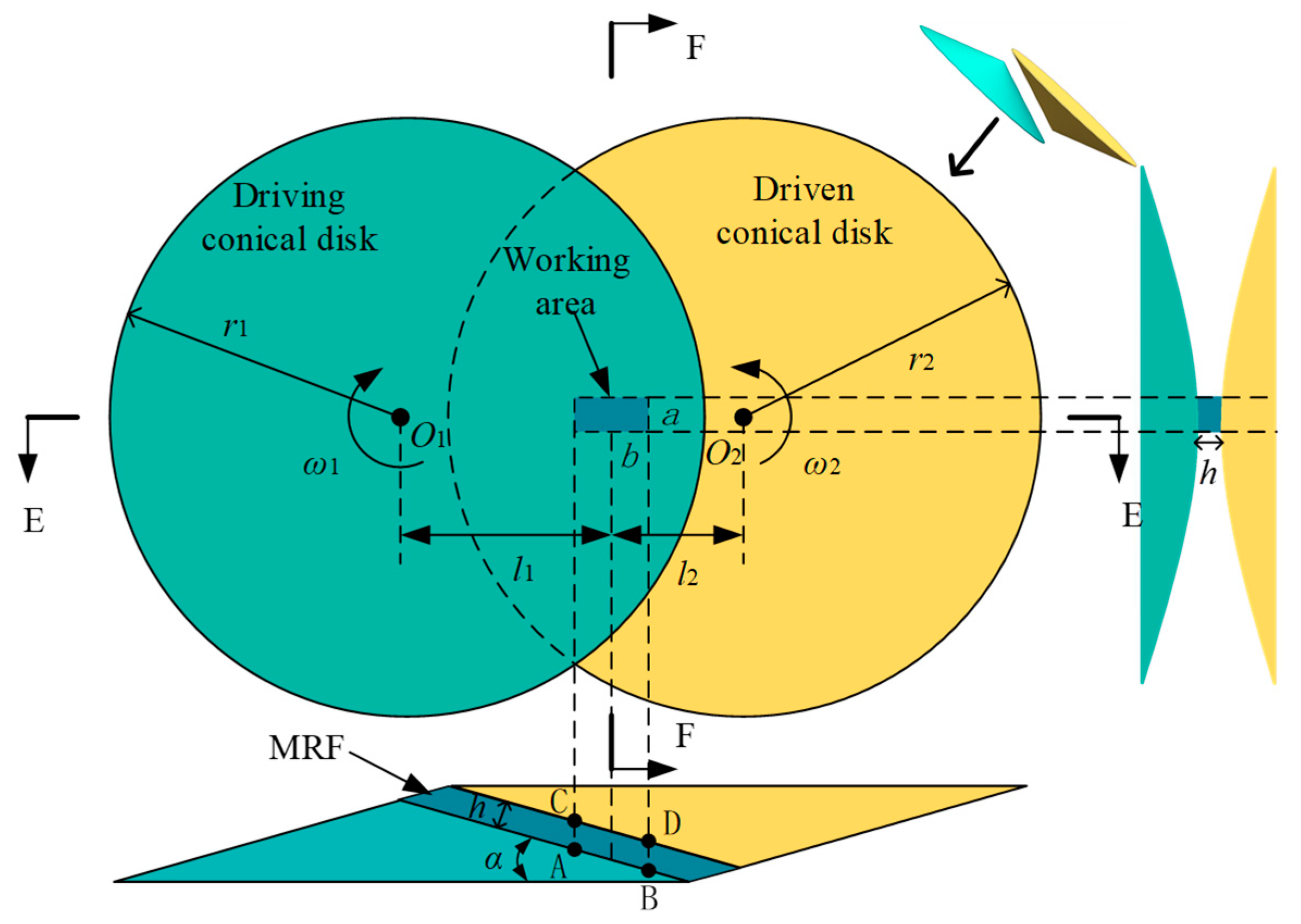
The torque output characteristic is the core feature of the MRFTD. The distribution of MRF between non-coaxial conical surfaces is more complex, and the cross-section of its working area is approximately a hyperbola, as shown in Figure 2. Taking the transmission between a single set of conical surfaces as an example, torque analysis is conducted and several ideal settings are made: (1) Soft magnetic particles are uniformly dispersed in the magnetorheological fluid; (2) The MRF in the working range is fully solidified. (3) Ignore the influence of gravity and hysteresis effect.
As shown in Figure 2, the green area represents the driving conical disk, the yellow area represents the driven conical disk, and the blue area represents the MRF. The length and width of the working area of the MRF are a and b, respectively, and its size is affected by the bottom angle of the conical disk.
(1) Calculation of the sizes of a and b
When the conical angle disk is very small, it can be seen from Figure 2 that the profile in the F-F direction is approximately a set of hyperbolas. The maximum effective height distance h of the MRF working gap is 2 mm, and its hyperbolic equation can be expressed as:
x 2 / a 2 y 2 / b 2 = 1
Substituting the two points on the hyperbola gives the expression of the equation. By substituting the effective height into the equation, the value of a can be determined. The value of b is determined by the arrangement of the coils and the structural dimensions of the conical disk.
(2) Torque calculation
When the MRF in the working area is excited by a magnetic field, it will change from a liquid state to a state similar to that of a Bingham fluid. According to the viscoplastic composition equation of the Bingham fluid, the shear yield stress of the MRF at this time is shown in Equation (2):
τ = τ 0 ( B ) sgn ( γ ˙ ) + η γ ˙
where τ 0 ( B ) represents the magnetoinduced shear stress; γ ˙ is the shear rate, and η is the dynamic viscosity of the MRF. The Sign function (abbreviated as sgn) is a mathematical function. When the shear rate is greater than 0, its value is 1; when the shear rate is 0, its value is 0.
The rotation centers of the driving and driven conical disks are O1 and O2, respectively. And the distances from the rotation centers to the MRF working area are l1 and l2. The rotational speeds of the driving and driven conical disks are ω1 and ω2, respectively. The rotational speed is inversely proportional to the distance, and thus it can be obtained:
ω 1 ω 2 = l 2 l 1
As shown in Figure 2, the horizontal velocities of points A, B, C, and D are respectively Va, Vb, Vc, and Vd. And the minimum vertical distance between the two conical discs is h. Then, it can be obtained that:
V A = ω 1 l 1 b 2 V B = ω 1 l 1 + b 2 V C = ω 1 l 2 + b 2 V D = ω 1 l 2 b 2
The equation for shear rate is:
γ ˙ = V 1 V 2 h  
The maximum shear rate is:
γ ˙ max = max γ ˙ AC , γ ˙ BD
After sorting, it can be obtained:
γ ˙ max = γ ˙ AC = b ω 1 2 1 + l 1 l 2
If the torque on the A–C section is dT, then we can obtain:
d T = a l 1 τ d b
Substituting Equation (2) into Equation (8), the total torque Ttotal of the magnetorheological conical disk drive can be obtained as:
T total = 0 b a l 1 ( τ 0 ( B ) + η γ ˙ ) d b = 0 b a l 1 τ 0 ( B ) d b + 0 b a l 1 η γ ˙ d b
It can be known from Equation (9) that the torque of the magnetorheological conical disk drive can be composed of:
T m = 0 b a l 1 τ 0 ( B ) d b T η = 0 b a l 1 η γ ˙ d b
Among them is the viscous torque of the MRF, which is not affected by the magnetic field and can be ignored compared with. Finally, it can be obtained that:
T total = T m = 0 b a l 1 τ 0 ( B ) d b
Among them, the magnitude of the magnetoshear stress is related to the MRF. For the structure designed in this paper, a is 19.66 mm and b is 21 mm. Since the structure designed in this paper has two sets of transmission conical surfaces, it can be calculated that the stably transmitted torque is 7.36 N·m. The torque values obtained from theoretical analysis are those under completely ideal conditions. The torque values in actual situations will be slightly lower than this value.

4. Research on Electromagnetic Field of Non-Coaxial Conical Disk MRFTD

4.1. Magnetic Circuit Design of MRFTD

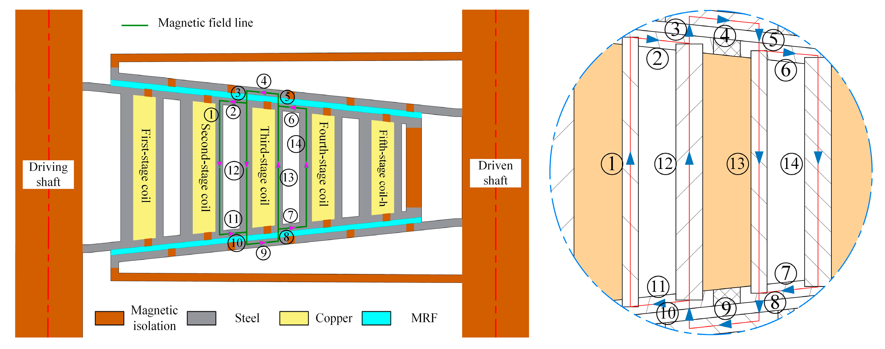
By rationally arranging the magnetic isolation and magnetic conduction materials and optimizing the magnetic field distribution path, the magnetic field can be concentrated as much as possible and pass through the working area of the MRF efficiently. One of the first-stage coil drive groups was taken as an example to calculate the magnetic circuit. In order to simplify the calculation, the following assumptions will be made: ① Assume that the magnetic field lines are completely closed and all pass through the working area of the MRF. ② Suppose the magnetic permeability of the same material is of the same magnitude everywhere and is a constant value. ③ Ignore the magnetic resistance between each component. ④ Suppose the magnetic fluxes in each part of the magnetic circuit are equal. The magnetic circuit structure of the final non-coaxial conical disk MRFTD is shown in Figure 3.
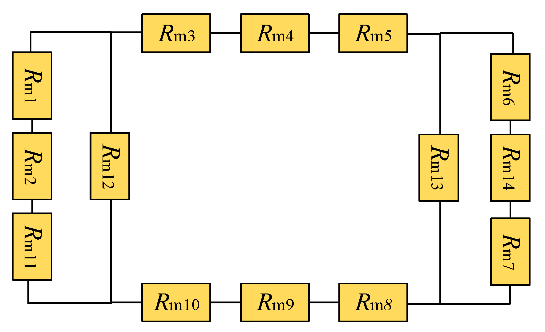
As shown in Figure 3, the magnetic circuit of the non-coaxial conical disk MRFTD forms a closed loop in the entire magnetic conductive material, passing through the magnetic conductive ring, the conical surface of the driving disk, the MRF and the conical surface of the driven disk in sequence. The magnetic circuit comprises three parts: the main magnetic circuits (③, ④, ⑤, ⑧, ⑨, and ⑩), the first branch magnetic circuits (①, ②, ⑫, and ⑪), and the second branch magnetic circuits (⑥, ⑭, ⑦, and ⑬). After being connected in parallel, these branch circuits are then connected in series with the main magnetic circuit to form a complete closed magnetic loop. After clarifying the magnetic circuit, the magnetic resistance in the magnetic circuit needs to be calculated. According to the magnetic circuit structure diagram, the equivalent magnetic resistance in the magnetic circuit can be divided, and the relationship between each magnetic resistance is shown in Figure 4.
According to Ohm’s law of magnetic circuits, the calculation equation of magnetic resistance is:
R m k = l k μ k A m k
In the equation, k represents the magnetic resistance in the magnetic circuit, Rmk is the Kth magnetic resistance, lk is the length of the magnetic circuit, μk is the magnetic permeability of the material, and Amk is the cross-sectional area perpendicular to the direction of the magnetic circuit.
The calculation equation for series and parallel magnetic resistance can be expressed as follows:
R m k , k + 1 = R m k + R m k + 1 1 R m k , k + 1 = 1 R m k + 1 R m k + 1
According to the calculation Equation (14), the magnetoresistance of each part can be obtained as follows:
  R m 1 = l 1 μ 1 π ( R 2 2 R 1 2 )   R m 12 = l 2 μ 12 π ( R 4 2 R 3 2 )   R m 13 = l 3 μ 13 π ( R 6 2 R 5 2 )     R m 14 = l 4 μ 14 π ( R 8 2 R 7 2 )   R m 2 = R m 6 = R m 7 = R m 11 = R 4 R 1 μ 2 π a l 7   R m 3 = R m 5 = R m 8 = R m 10 = 2 l 6 μ 3 a b   R m 4 = R m 9 = R 10 R 9 μ 4 a l 5
In the equation, R1 to R8 represent the radii of each magnetic conducting ring, l1 to l4 represent the heights of each magnetic conducting ring, l5 is the thickness of the driven cone disk, l6 is the working gap width of the MRF, l7 is the thickness of the driving cone disk, and μk (k = 1 to 15) is the magnetic permeability of each material.
Then, according to the series-parallel formula of magnetic resistance (13), the total magnetic resistance of the magnetic circuit can be obtained.
R m = R m 1 , 2 , 11 , 12 + R m 3 + R m 4 + R m 5 + R m 6 , 7 , 13 , 14 + R m 8 + R m 9 + R m 10
The magnetic flux is obtained by Ohm’s law of magnetic circuits.
ϕ = N I R m
Then the magnetic flux in the entire magnetic circuit can be obtained as follows:
ϕ = ϕ 3 = B 3 S 3 = B 3 a b 2
where S3 represents the effective area of the MRF working region, and B3 represents the magnitude of the magnetic induction intensity at the MRF working region.
The required number of coil ampere-turns is calculated as:
N I = R m ϕ = R m B 3 a b 2

4.2. Electromagnetic Field Analysis

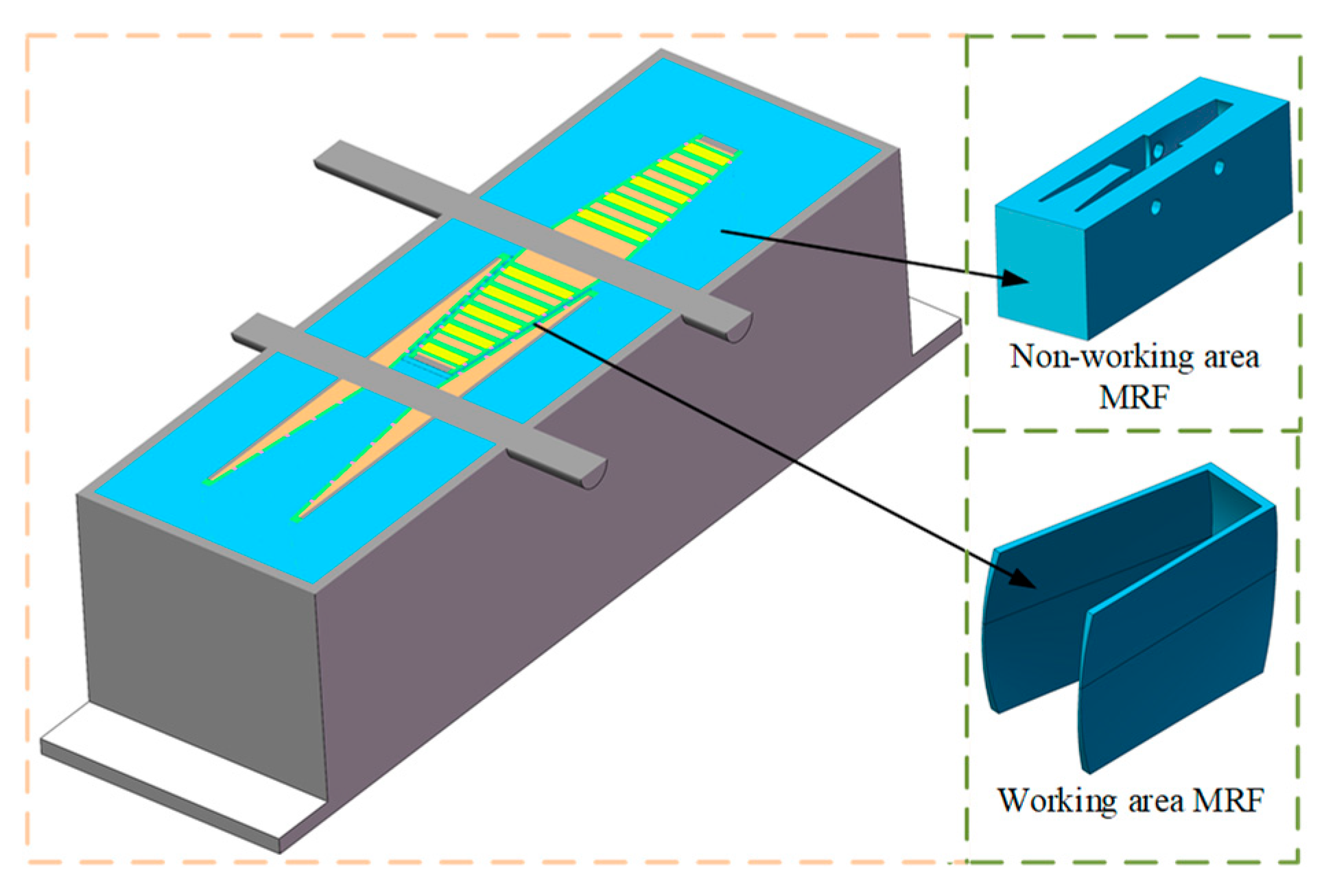
Due to the complex and asymmetric structure of the non-coaxial conical disk MRFTD, 3D electromagnetic simulation analysis of the MRFTD was carried out in COMSOL Multiphysics 6.1 to obtain the distribution of its magnetic induction intensity. The structure of the non-coaxial conical disk MRFTD is complex. To improve the computational efficiency, the model should be simplified before the simulation. Under the premise of not affecting the magnetic circuit of the speed governor, the standard parts, bearing end covers, and holes on the structure, as well as other features and parts, were ignored. The final simplified model is shown in Figure 5.
After the model is imported, materials need to be added to each part. Add materials to the model according to the materials used for each part of the governor, as shown in Figure 6.
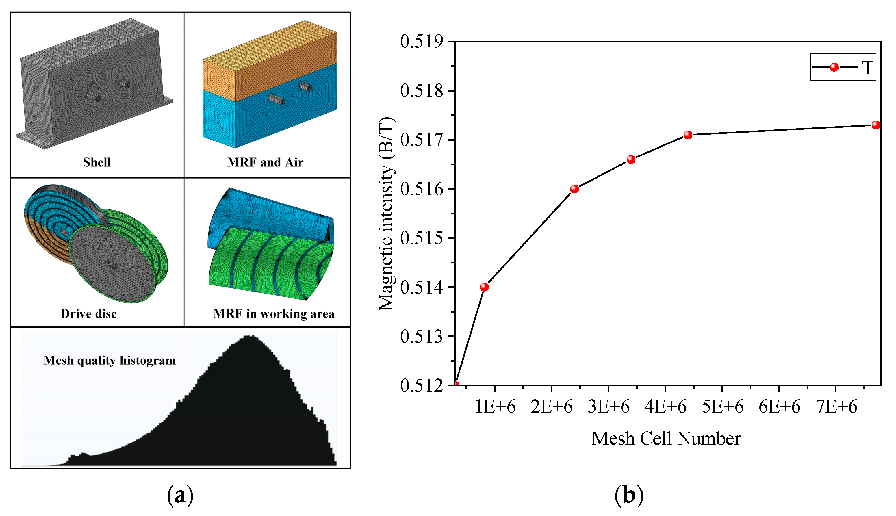
To reduce the computational cost, the simulation model needs to be manually meshed. The mesh density of the MRF in the working area was increased, and the geometrically regular driving shaft and driven shaft adopted the sweeping meshing method. The meshing results are shown in Figure 7 and Table 1.
Mesh quality plays a critical role in determining the calculation accuracy of the entire model. The histogram of the mesh division unit quality and the division results are presented in Figure 7a. Figure 7b shows the maximum magnetic induction intensity when number of mesh cells are 7,707,533, 4,401,015, 3,397,902, 2,402,675, 817,989, and 303,289, which are 0.512 T, 0.514 T, 0.516 T, 0.5166 T, 0.5171 T, and 0.5173 T, respectively. As can be seen, when the number of mesh cells exceeds 2,402,675, the maximum magnetic induction intensity remains nearly constant. Considering the computational capacity of the computer, the simulation employs a total of 3,397,902 mesh cells, achieving an average mesh quality of 0.6307. Detailed information is provided in Table 1.
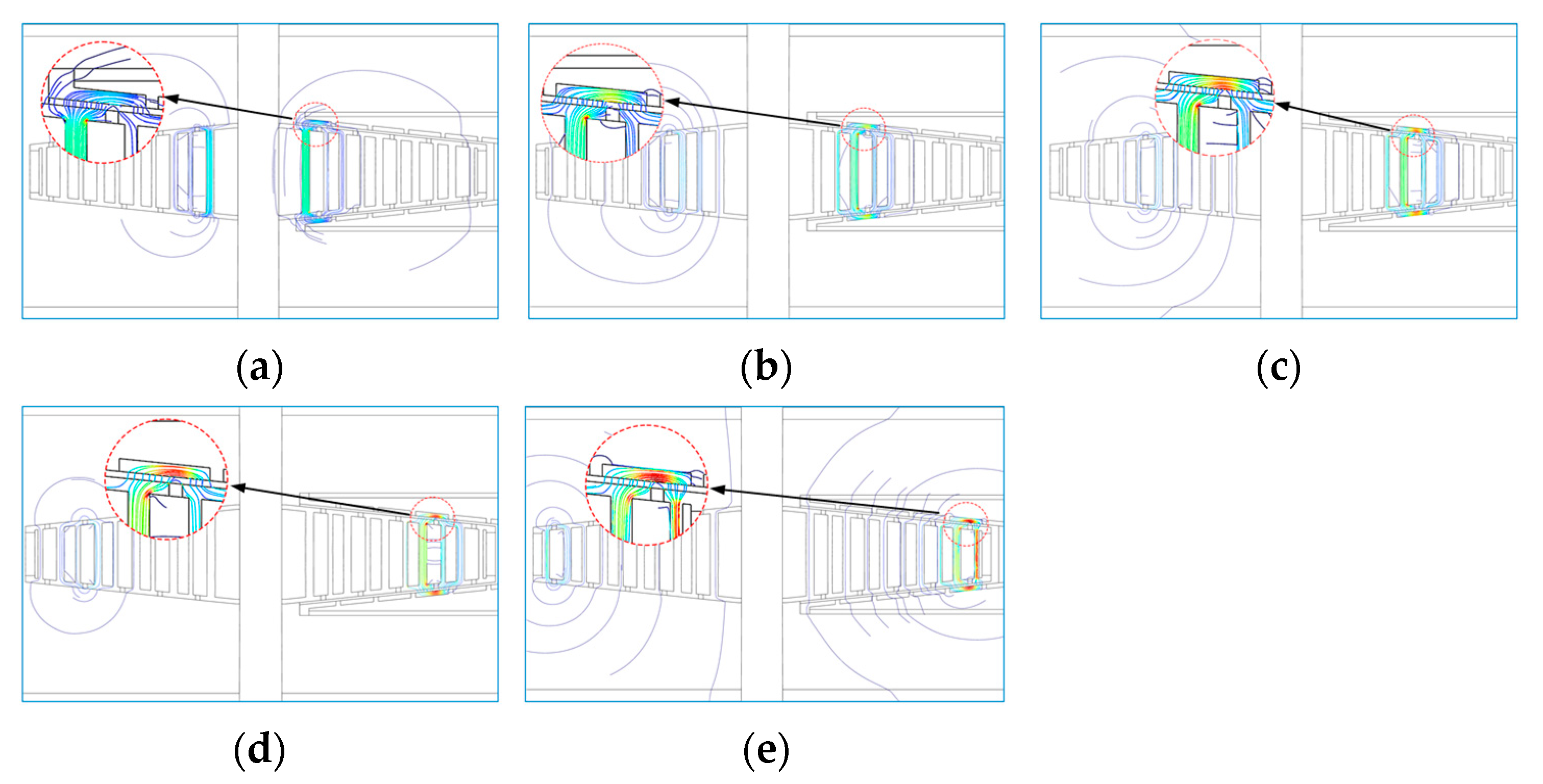
To accurately characterize the distribution features of magnetic field lines, the plane where the axes of the two transmission shafts lie is selected as the observation section. The distribution map of magnetic field lines is shown in Figure 8.
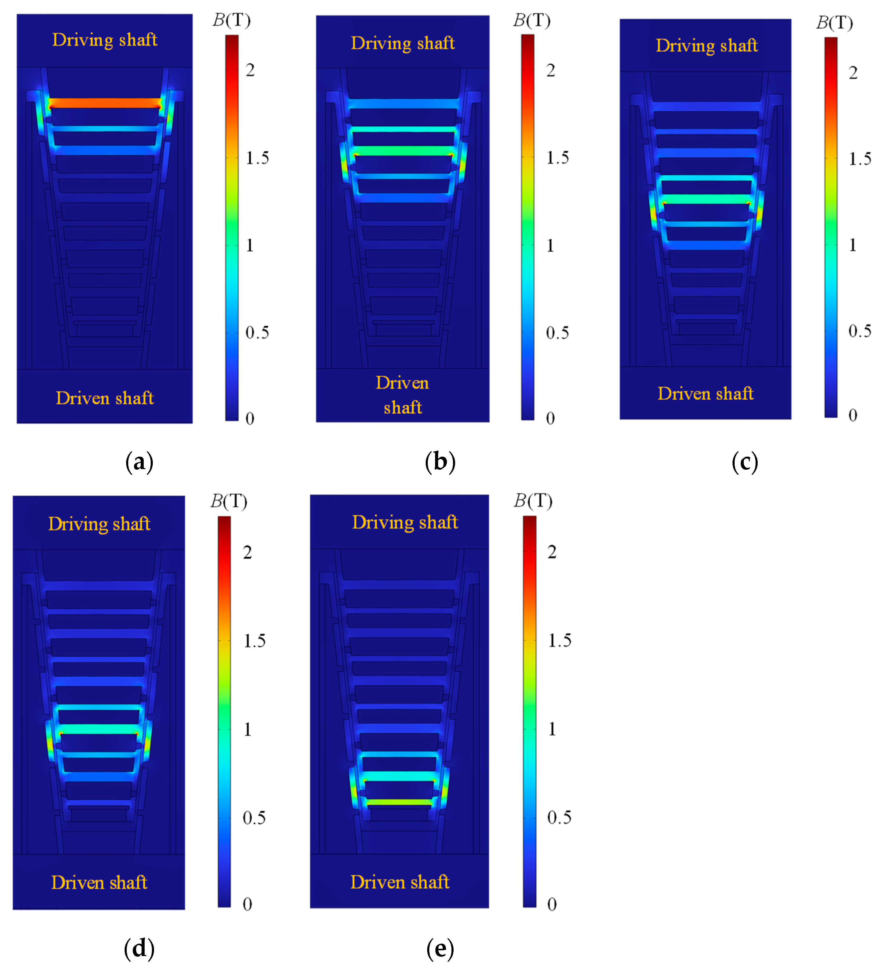
As shown in Figure 8, the magnetic field lines form a closed loop in the magnetic flux guide ring, the conical surface of the driving conical disk, the MRF, and the conical surface of the driven conical disk. Most of the magnetic field lines pass vertically through the working area of the MRF. The distribution cloud chart of the magnetic induction intensity of the transmission part on the selected cross-section is taken as the observation object, as shown in Figure 9. The results show that the magnetic fields generated by each coil are concentrated in the corresponding working area of the MRF. The guiding effect of the magnetic rubber and the magnetic flux guide ring on the magnetic field is obvious. The average magnetic induction intensity in the magnetic flux guide ring is the highest, and in the working area of the MRF, the magnetic induction intensity is generally higher than 0.5 T, meeting the working requirements of the MRF.
The 3D distribution model of the magnetic induction intensity in the working area of the MRF is constructed, as shown in Figure 10. Under the effect of each stage of coil, the magnetic saturation area of the MRF is highly consistent with the transmission area of the MRF, while the magnetic induction intensity in other areas of the MRF is significantly lower than that in the transmission area.
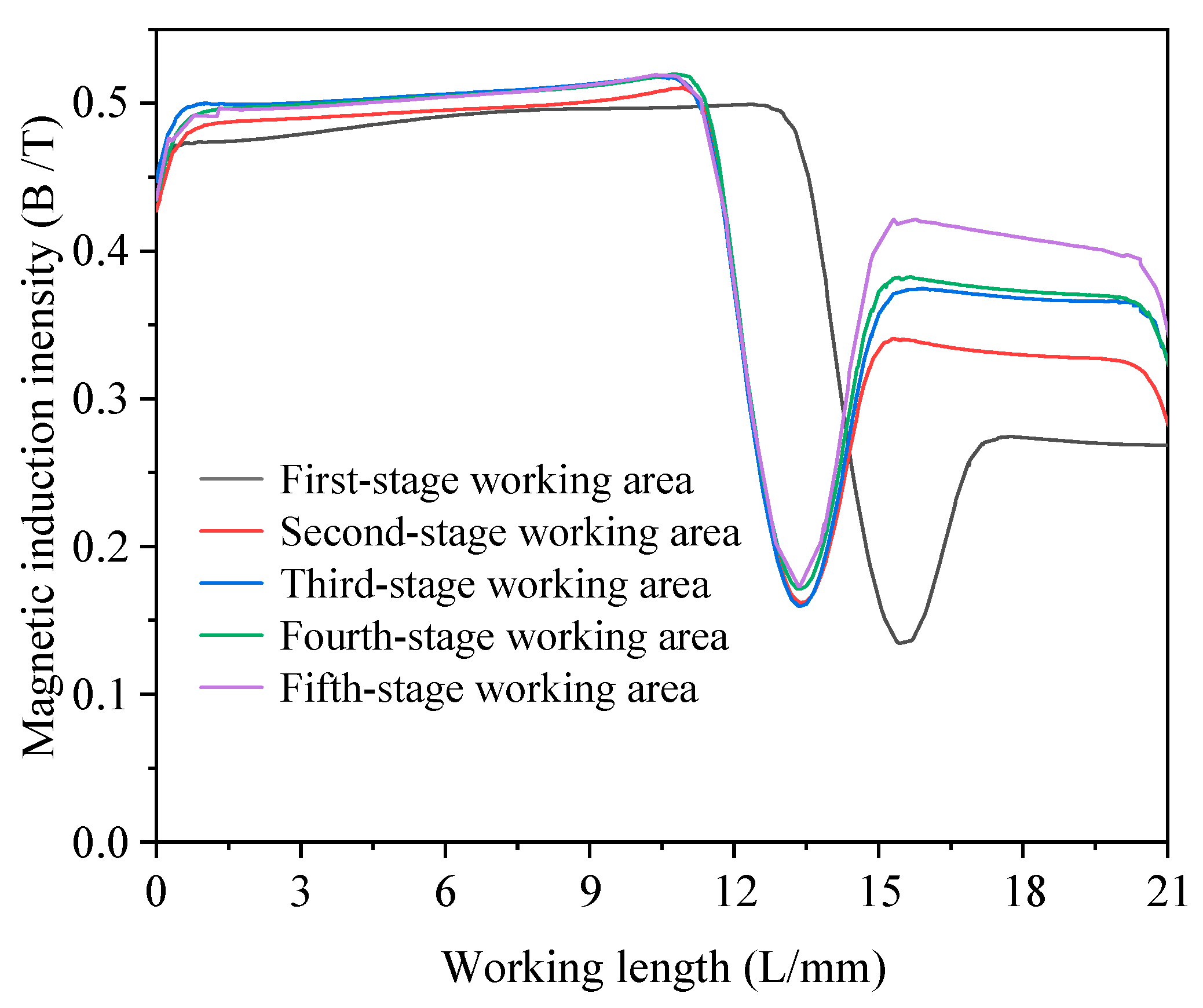
To quantitatively analyze the magnetic induction intensity in the working area, the magnetic induction intensity on the centerline of the working area of each stage of the coil was selected as the research object. The magnetic induction intensity on the centerline is shown in Figure 11. It is clearly observed that the magnetic induction intensity within the working gap is divided into two parts. The magnetic induction intensity before 10 mm is generally above 0.5 T, and the magnetic induction intensity after 15 mm is above 0.3 T. The magnetic field lines generated by the coil are closed around the coil and are more concentrated in the center area of the coil. Therefore, the closer to the center of the coil, the greater the magnetic induction intensity. At the same time, the maximum magnetic induction intensity on the centerline of the working area of the first to fifth stage coils are 0.49934 T, 0.51105 T, 0.51818 T, 0.51972 T, and 0.51980 T, respectively, which meet the requirements of the transmission.

4.3. Influencing Factors of Magnetic Induction

Parameters such as coil current, working gap, the conical angle of disk and magnetic conductive material affect the distribution of magnetic induction intensity in the working area. Based on the principle of controlling variables, this part conducts research respectively.

4.3.1. Coil Current

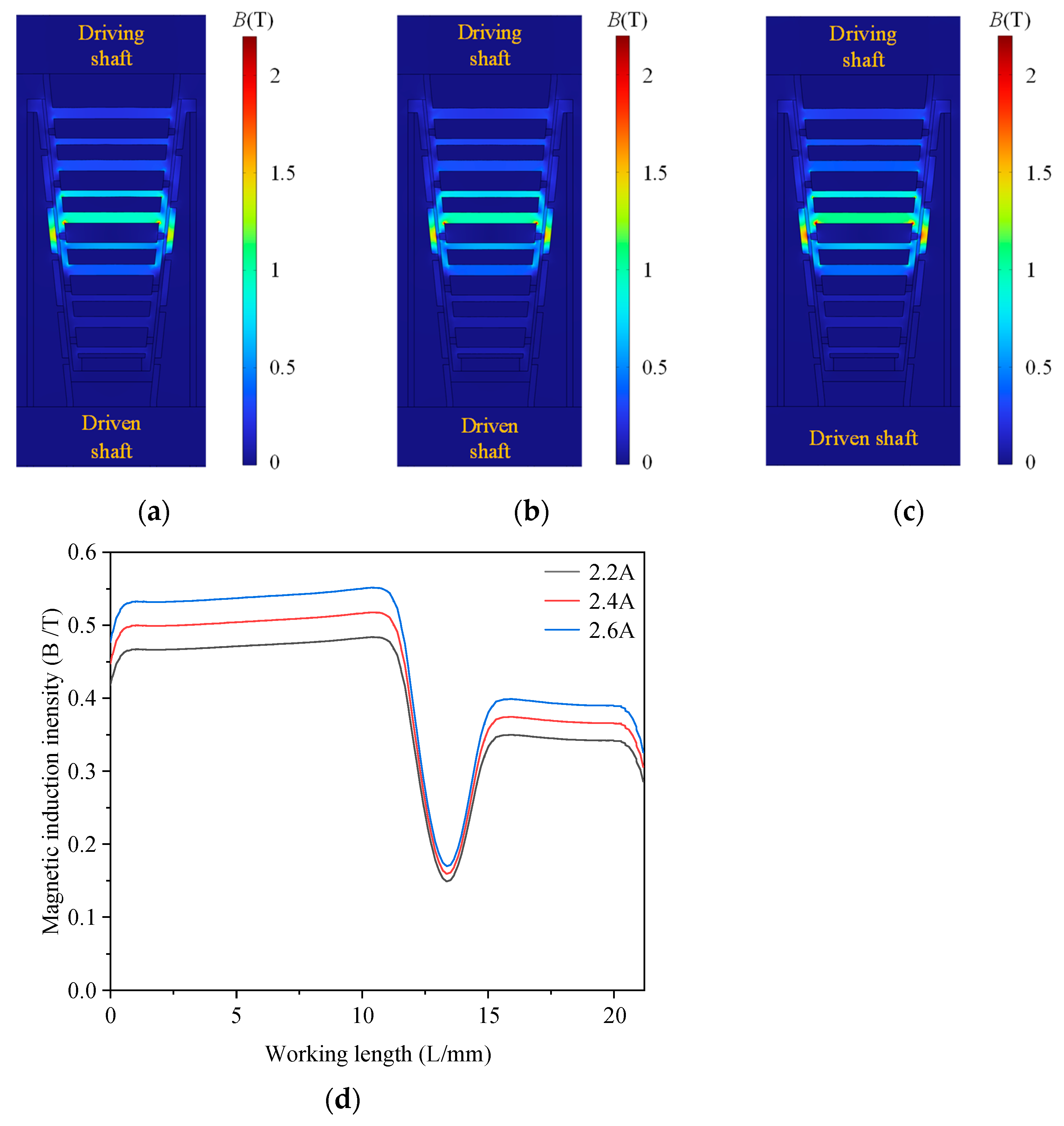
Taking the third-stage coil transmission group as an example, the number of turns of the coil is set to 300, and currents of 2.2 A, 2.4 A and 2.6 A are applied respectively. Meanwhile, the conical angle of the disk is 6°, the materials of each part are the same, and the minimum distance between the two conical disk surfaces is 1.5 mm. Based on this parameter combination, the electromagnetic field simulation analysis of the non-coaxial conical disk MRFTD is carried out. The results are shown in Figure 12.
It can be known from Figure 12 that when the current of the excitation coil increases from 2.2 A to 2.6 A, the magnetic induction intensity in the working area gradually increases. The average magnetic induction intensities before 10 mm were 0.4723 T, 0.5054 T, and 0.5386 T, respectively, and their growth rates were 7% and 6.5% in sequence. The average magnetic induction intensities after 15 mm were 0.3413 T, 0.3653 T, and 0.3892 T, respectively, and their growth rates were 7% and 6.5% in sequence. The magnetic induction intensities of both regions increase with the increase of current, but the growth rate gradually decreases with the increase of current.
As the current increases, the distribution of the magnetic induction intensity remains unchanged in the spatial distribution. That is, the magnetic induction intensity of the MRF in the working area is relatively large, while it is almost zero in other areas, indicating that the magnetic isolation effect is good.

4.3.2. Working Gap

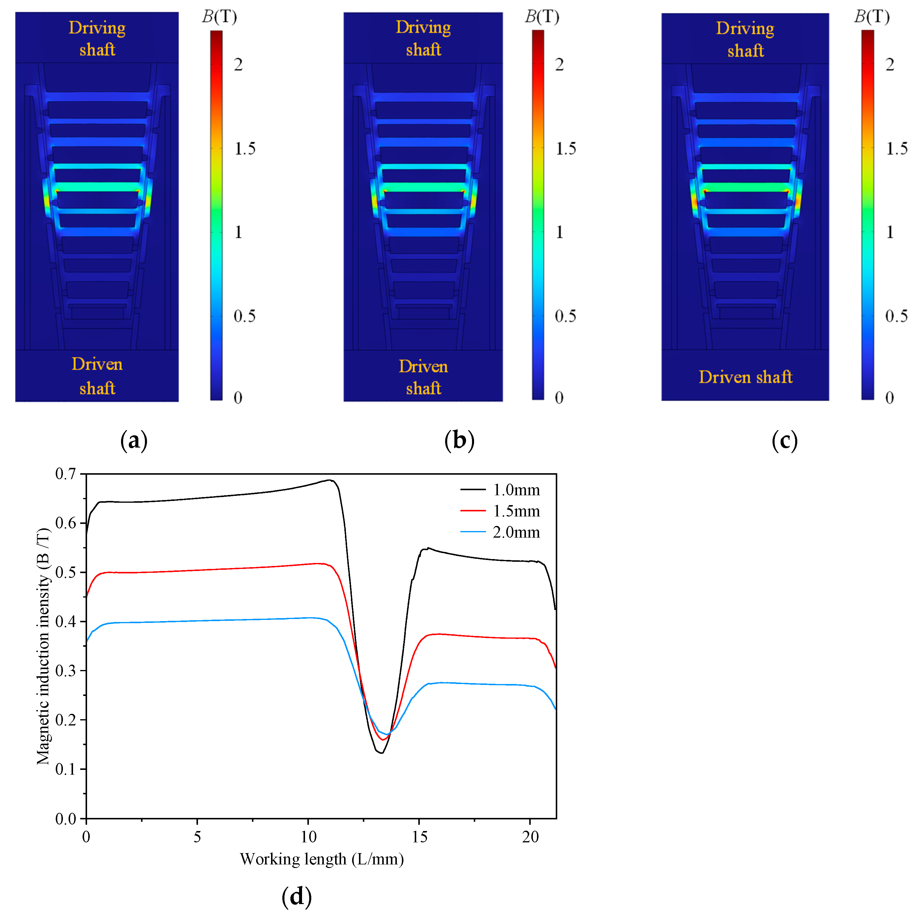
The size of the working gap has a significant impact on the transmission performance of the MRFTD. To explore the influence of the law of the working gap, taking the third-stage coil transmission group as an example, the minimum distances between the two conical disk surfaces are set as 1.0 mm, 1.5 mm, and 2.0 mm, respectively. Meanwhile, the number of coil turns is 300, the coil current is 2.4 A, the conical angle of the disk is 6°, and the materials of each part are the same. Based on this parameter combination, electromagnetic field simulation was carried out, and the results are shown in Figure 13.
It can be obtained from Figure 13 that when the working gap increases from 1.0 mm to 2 mm, the magnetic induction intensity in the working area gradually decreases. The average magnetic induction intensities before 10 mm were 0.6548 T, 0.5054 T, and 0.3997 T, respectively, and the decrease rates were 22.8% and 20.9% in sequence. The average magnetic induction intensities after 15 mm were 0.5257 T, 0.3653 T, and 0.2714 T, respectively, and the decrease rates were 30.5% and 25.7% in sequence.
Although a smaller gap can enhance the magnetic induction intensity, an overly small gap will significantly increase the difficulty and cost of processing. On the premise of meeting the transmission requirements, this paper determines the working gap parameter of 1.5 mm.

4.3.3. Conical Angle of the Disk

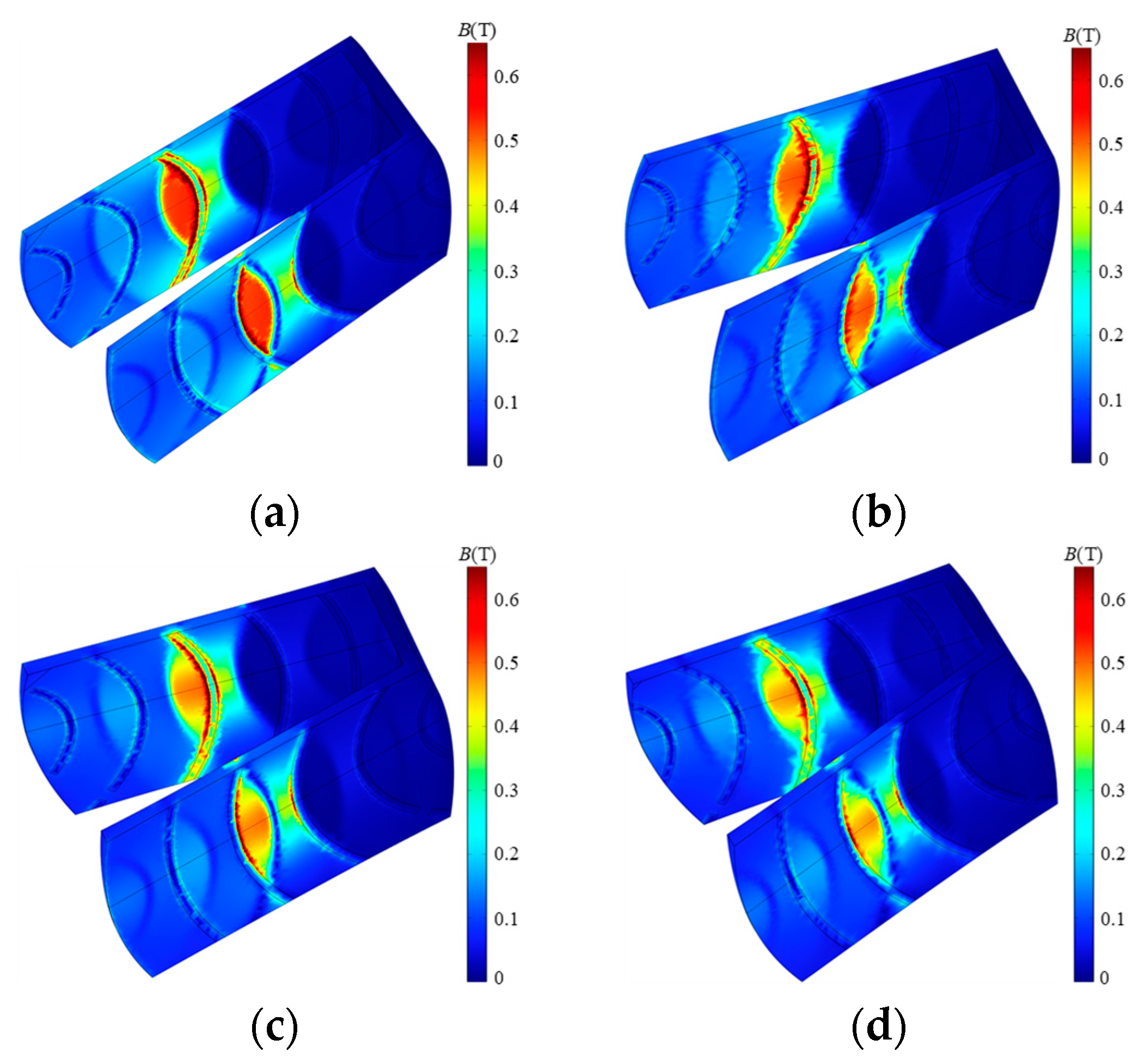
The conical angle of the disk will affect the area of the MRF working area, thereby influencing the magnetic induction distribution. Taking the third-stage transmission group as an example, the number of coil turns is 300, the coil current is 2.4 A, the working gap is 1.5 mm, and the materials of each part are the same. The variation laws of the magnetic induction intensity in the working area when the conical angle of the disk is 3°, 6°, 9° and 12°, respectively, were studied. The results are shown in Figure 14.
It can be seen from Figure 14 that when the conical angle of the disk increases from 3° to 12°, the magnetic induction intensity in the working area gradually decreases. The average magnetic induction intensities before 10 mm were 0.5255 T, 0.5054 T, 0.4882 T, and 0.4728 T, respectively, decreasing by 38.4%, 33.9%, and 31.6% successively. The average magnetic induction intensities after 15 mm were 0.3650 T, 0.3653 T, 0.3707 T, and 0.3690 T, respectively, and the average magnetic induction intensities were basically the same. When the conical angle of the disc is less than 6°, the MRF in the working area reaches a magnetic saturation state.
Figure 15 shows the magnetic induction distribution of the MRF working area at different angles. With the increase of the conical angle, the effective working area of the MRF that meets the transmission requirements gradually decreases. When the conical angle of the disk is less than or equal to 6°, more than 90% of the area where the two conical surfaces cross can meet the transmission requirements. However, when the conical angle increases to 12°, only about 50% of the area meets the transmission conditions.
Although a smaller conical angle of the disk is beneficial to improving the transmission efficiency, the angle that is too small will limit the flow of the MRF in the working gap during the transmission process. Therefore, in this paper, the conical angle of the disk is finally designed to be 6°.

4.3.4. Magnetic Conductive Material

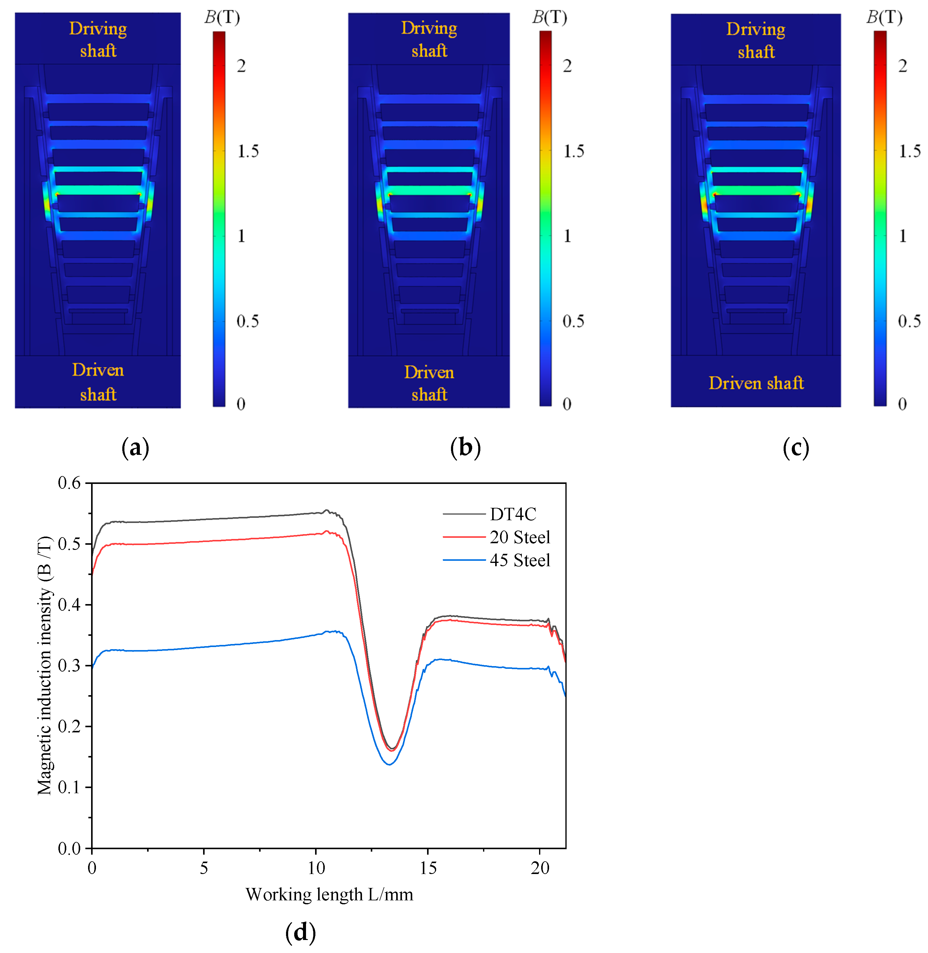
The properties of magnetic conductive materials can affect the magnetic induction distribution. Taking the third-stage coil transmission group as an example, the variation law of the magnetic induction intensity in the working area when the number of coil turns is 300, the current magnitude is 2.4 A, the working clearance is 1.5 mm, the materials of each part are the same, and the magnetic conductive materials are DT4C, 20 steel and 45 steel respectively. The results are shown in Figure 16.
It can be obtained from Figure 16 that the magnetic conductive material has a significant influence on the magnetic induction intensity. When the magnetic conductive material is DT4C, the magnetic induction intensity at each position within the working gap is the maximum. The average magnetic induction intensity before 10 mm is 0.5495 T, and the average magnetic induction intensity after 15 mm is 0.3755 T. When the magnetic conductive material is 45 Steel, the magnetic induction intensity is the smallest. The average magnetic induction intensity before 10 mm is 0.3332 T, and the average magnetic induction intensity after 15 mm is 0.2998 T. When the magnetic conductive material is 20 Steel, the magnetic induction intensity is similar to that of DT4C. The average magnetic induction intensity before 10 mm is 0.5054 T, and the average magnetic induction intensity after 15 mm is 0.3653 T. Both 20 Steel and DT4C meet the transmission requirements. Considering the processing and economic costs comprehensively, 20 Steel is adopted as the magnetic conductive material in this paper.

5. Experiments and Discussion

5.1. Experimental System

To verify the performance of the MRFTD proposed in the paper, the prototype of the non-coaxial conical disk MRFTD was processed, and a performance test experimental bench, as shown in Figure 17, was set up. Experiments on the magnetic field intensity characteristics, transmission characteristics and torque response characteristics were carried out.
In the experiment, the current source supplies current to the five coils. The frequency converter regulates the motor speed. The torque/speed transmitter converts the sensor signal into a voltage signal, powered by the power supply. Finally, the NI acquisition card receives the voltage signal output from the torque/speed transmitter. The Gaussmeter measures the magnetic induction intensity in the working gap. The specific parameters of the main components are shown in Table 2.

5.2. Magnetic Field Intensity Characteristics

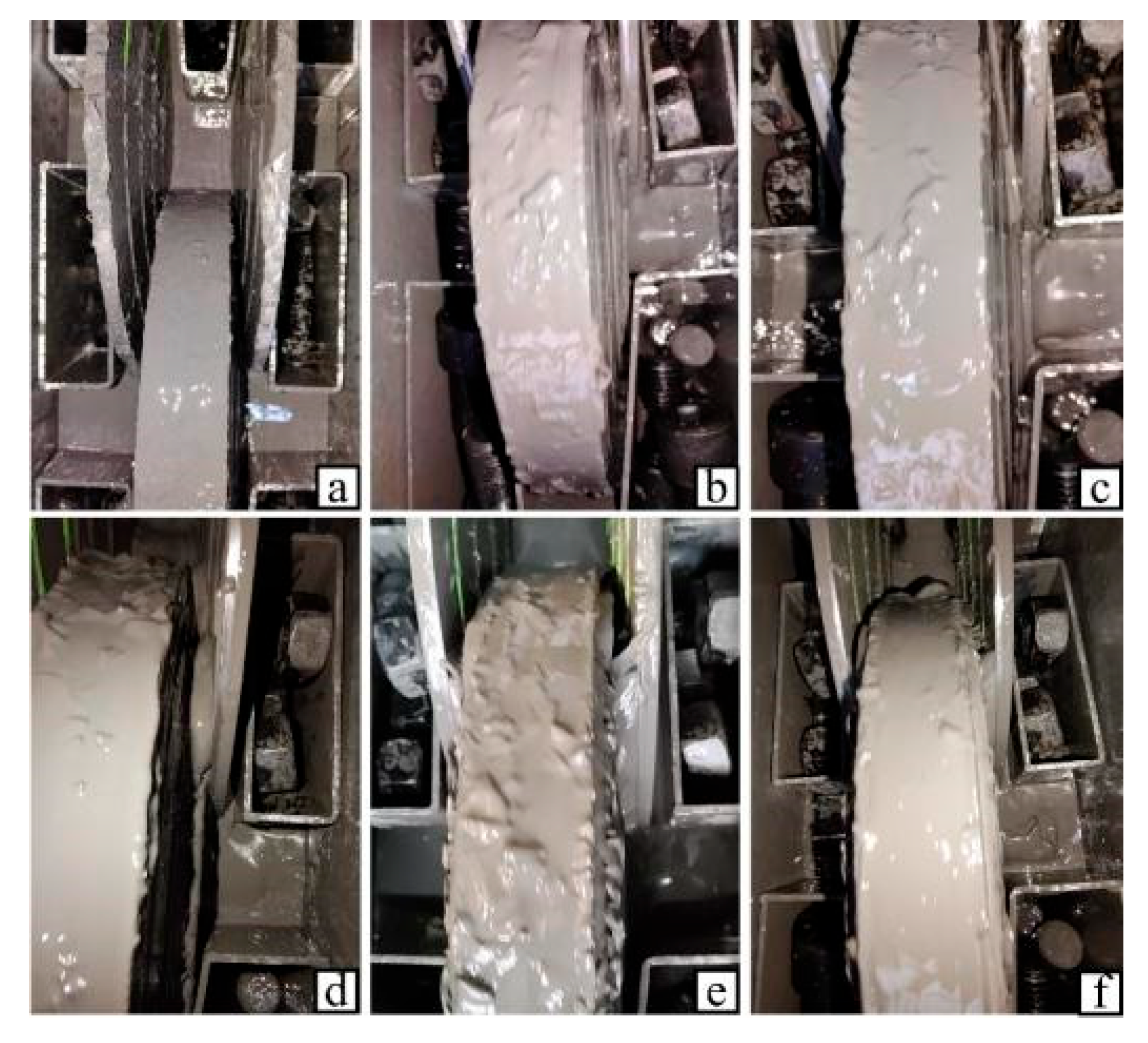
The magnetic induction intensity within the working gap has a significant influence on the transmission performance of the MRFTD. It is commonly accepted that when the magnetic field intensity reaches 0.5 T, the MRF reaches magnetic saturation. Figure 18 shows the rheological effect diagram of each stage coil in the non-coaxial conical disk MRFTD after applying current. Figure 18a shows the non-energized state, and Figure 18b to Figure 18f, respectively, show the energized state of the five stage coils. It can be observed that the MRF near the coils at all levels has solidified, and the solidification effect is good.
Figure 19 shows the magnetic induction intensity data of the five-stage coils when they are respectively energized. The magnetic induction intensities of the five groups of coil drive groups show little difference under the condition of the same number of ampere-turns. With the continuous increase of the number of ampere-turns, their magnetic induction intensities all show an upward trend, but the growth rate slows down significantly. When the amp-turns reach 720, the magnetic induction intensity at the working area of each coil drive group is about 0.5 T, slightly lower than the simulation results, as there will be a tiny gap when the conical disk surface is assembled with the magnetic conducting ring, which increases the magnetic resistance here.

5.3. Transmission Characteristics

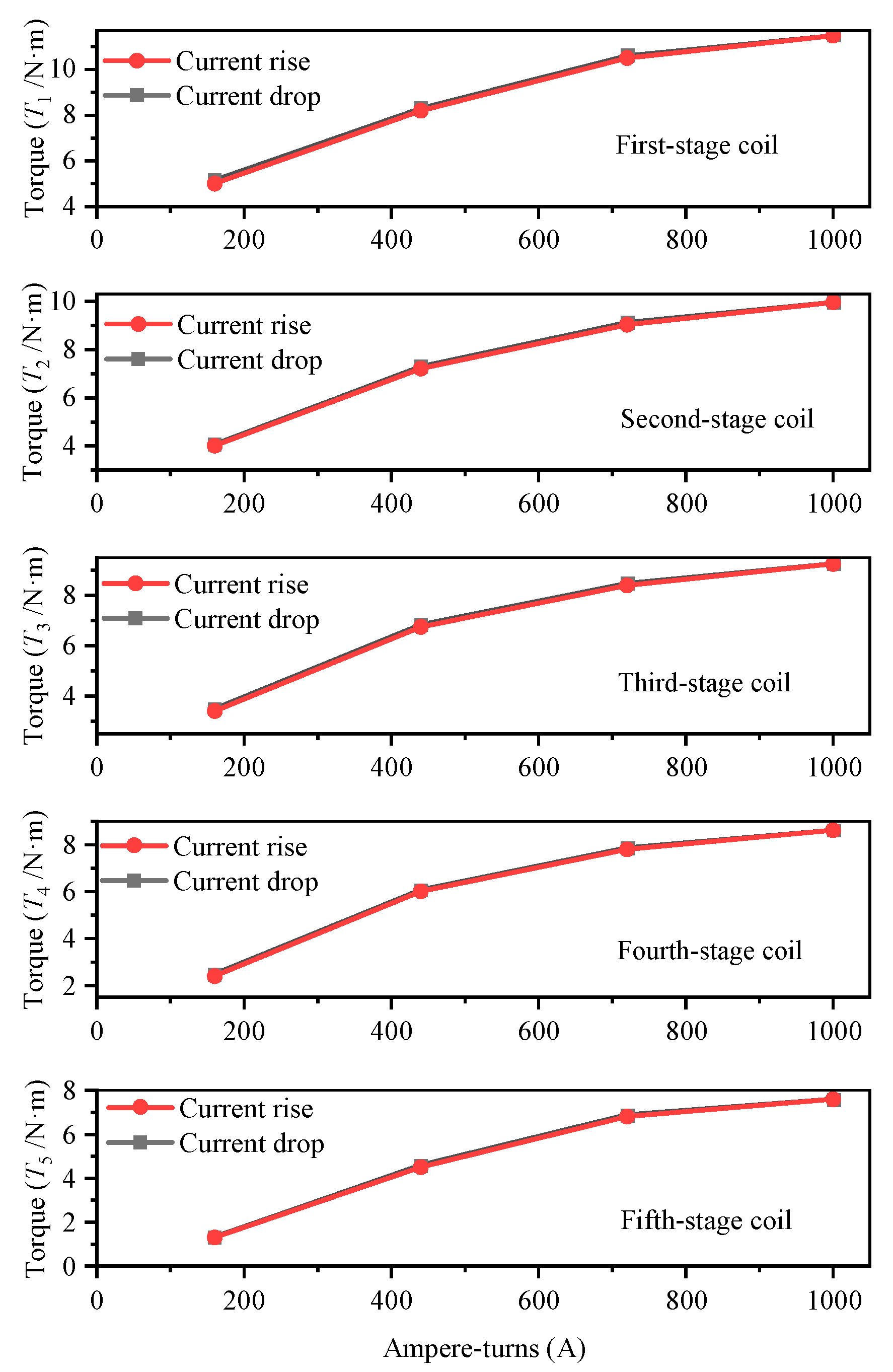
The transmission characteristics are used to describe the relationship between the torque of the output shaft of the MRFTD and the current passing through the excitation coil. When conducting the transmission characteristic experiments on the five transmission groups of the MRFTD, the motor speed was set at 50 r/min, and the ampere-turns of the excitation coil were increased from 160 to 1000, and then decreased from 1000 to 160 at an interval of 280. The transmission characteristic curve of the MRFTD was obtained, as shown in Figure 20.
As can be seen from Figure 20, with the increase of ampere-turns, the output torque of each transmission group increases, and the increasing trend is basically the same. When the ampere-turns exceed 720, the growth rate of the output torque slows down significantly. This occurs because the MRF approaches magnetic saturation, resulting in a decrease in the growth rate of shear stress. Under the same number of ampere-turns, the output torques of the first-stage to fifth-stage drive groups decrease successively. This is because the shear stress of the MRF in each level of the working area is basically the same, but the radius of action from the driven shaft decreases step by step, thereby resulting in a decrease in the output torque. Furthermore, the maximum torque that the MRFTD can stably transmit is 6.8 N·m, which is slightly smaller than the theoretical analysis value 7.36 N·m. The measured output torque is 0.56 N·m lower than the theoretical analysis result. The accuracy rate between the output torque test results and the theoretical analysis results reaches more than 92.4%, which has a relatively high level of confidence. There are several reasons for this: (1) In theoretical analysis, it is assumed that the particles of the MRF are uniformly distributed and completely solidified, ignoring the effects of hysteresis and gravity; (2) During assembly, there will be tiny gaps, which lead to a decrease in the magnetic induction intensity within the working area and a reduction in shear stress. During the process of current increase and decrease, the input torque remains largely consistent during both the current rise and drop phases, indicating that the hysteresis effect in the system is negligible.

5.4. Torque Response Characteristics

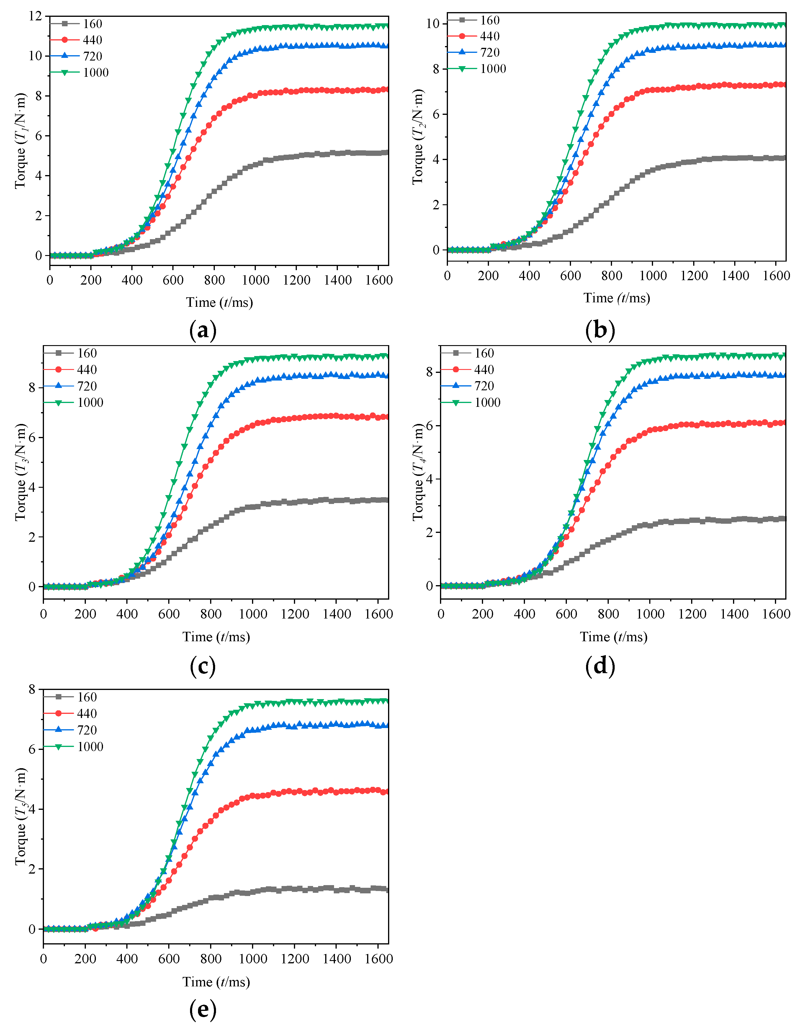
After the current of the excitation coil changes, the output torque of the MRFTD also changes accordingly, and the change process can be characterized by the torque response characteristics. When conducting the torque dynamic response characteristics experiment on the five transmission groups of the non-coaxial conical disc MRFTD, the motor speed was set at 50 r/min, the ampere-turns of the excitation coil increased from 160 to 1000 with an interval of 280, and the torque dynamic response characteristics of the five transmission groups under step current excitation were experimentally observed.
As shown in Figure 21, the response trends of the five drive groups after the current is applied to the coil are basically the same. The torque rises rapidly at the beginning and then gradually stabilizes. As the number of ampere-turns increases, the response speed improves. When the number of ampere-turns is 160, the output torque stabilizes around 1200 ms. When the number of ampere-turns increases to 1000, the output torque stabilizes around 900 ms, and the stabilization time is significantly shortened.

5.5. Temperature Characteristics

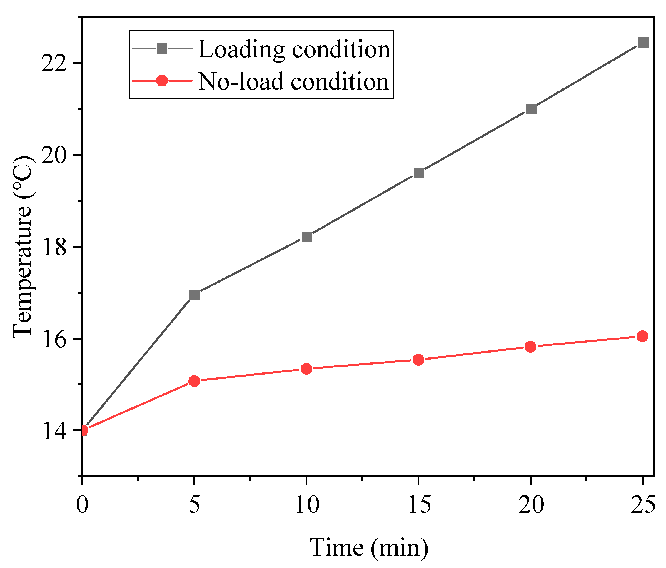
This part of the experiment investigated the temperature characteristics of the MRFTD under no-load conditions and loading conditions. In the no-load test, the excitation coil was not energized, and the motor speed was maintained at 50 r/min. In the loading condition, the excitation coil was supplied with 720 ampere-turns while the motor speed remained at 50 r/min.
As shown in Figure 22, under no-load condition, the heating rate in the working area of the MRF is relatively low, with the temperature increasing by only approximately 1.5 °C over a period of 25 min. This indicates that heat generation under no-load condition is minimal. Under the loading condition, the temperature in the working area of the MRF gradually increases and reaches 24.4 °C after 25 min, representing a total temperature rise of about 9 °C. These results demonstrate that the proposed novel transmission configuration exhibits favorable thermal performance.

6. Conclusions

(a) A novel configuration of non-coaxial conical disk MRFTD was proposed. Through the analysis of the dynamic transmission characteristics of MRF between the conical disk interface, the output torque of the transmission device was obtained through theoretical calculation.
(b) The magnetic circuit design of the non-coaxial conical disk MRFTD was carried out. Through electromagnetic field simulation analysis, the rationality of the structural design was verified. Meanwhile, the factors that affect the magnetic induction intensity in the working area of the MRF, such as current and working gap, were studied. The results show that the magnetic induction intensity in the working area increases with the increase of the current in the excitation coil, decreases with the increase of the working gap between the two cone discs, and is positively correlated with the magnetic permeability of the conical disc and the magnetic conducting ring materials. Both the effective working area range and the magnetic induction intensity decrease as the conical angle of the disc increases. The magnitude of the magnetic induction intensity on the center line is basically the same, but the effective working area range corresponding to different bottom angles shows significant differences.
(c) The prototype was processed, the non-coaxial conical disk MRFTD experimental bench was set up, and experiments such as magnetic field intensity distribution and torque response were carried out. The magnetic field intensity characteristic experiment shows that when the ampere-turns of the coil are 720, the magnetic induction intensity at the working area of each level of the coil drive group is close to 0.5 T, meeting the design requirements. The transmission characteristic experiments show that the no-load torque of the MRFTD is relatively small, and the stably transmitted torque is 6.8 N·m. The torque is less affected by the rotational speed and is close to the theoretically calculated value. The torque response characteristics indicate that at a higher coil ampere-turns ratio, the torque is nearly stable at 900 ms, and the response characteristics are good.
The MRFTD is an innovative intelligent device that leverages the rheological characteristics of MRF. It exhibits advantages such as rapid response, excellent controllability, strong reversibility, and a simple structure, making it highly promising for application in the field of transmission systems. This paper proposes a non-coaxial conical disk structure to address the issue of severe heating observed in traditional MRFTD. Comprehensive studies on torque, electromagnetic fields, and experimental validation were conducted, confirming the effectiveness of the proposed structure. Besides, further research could explore multi-cone disk group high torque transmission devices based on this design, enabling broader torque transmission ranges and enhanced speed regulation capabilities.

Author Contributions

X.W., Z.T. and W.L. conceived this research and formulated overarching research goals and aims. X.W., Z.T., W.L. and Y.G. performed the analysis and wrote the original draft of the manuscript. X.W., Z.C. and M.Z. set up the experiment system and completed the experiments. X.W., W.L., Z.C., M.Z. and Y.G. edited and reviewed the manuscript; Z.T. and X.W. oversaw the progress of the study and the visualization of the results. All authors have read and agreed to the published version of the manuscript.

Funding

This research was funded by the Basic Science (Natural Science) Research Project of the Jiangsu Higher Education Institutions Project Funding (22KJA460013) and the National Natural Science Foundation of China (52375069).

Institutional Review Board Statement

Not applicable.

Informed Consent Statement

Not applicable.

Data Availability Statement

The original contributions presented in this study are included in the article. Further inquiries can be directed to the corresponding author.

Acknowledgments

The authors would like to thank the editors and reviewers for their valuable comments and constructive suggestions.

Conflicts of Interest

The authors declare no conflicts of interest. The funders had no role in the design of the study; in the collection, analyses, or interpretation of data; in the writing of the manuscript, or in the decision to publish the results.

References

  1. Ji, J.J.; Wu, X.F.; Tian, Z.Z. Effect on the Sedimentation Stability of Magnetorheological Fluid by Micro-nano Composite System. J. Magn. 2023, 28, 172–180. [Google Scholar] [CrossRef]
  2. Shiao, Y.; Bollepelly, M. Effect of Pole Head Profile on Torque Performance of a Disc-Type Multipole Magnetorheological Brake. Appl. Sci. 2023, 13, 8327. [Google Scholar] [CrossRef]
  3. Wu, X.F.; Huang, C.H.; Tian, Z.Z. Development of a novel magnetorheological fluids transmission device for high-power applications. Smart Mater. Struct. 2019, 28, 05502. [Google Scholar] [CrossRef]
  4. Wu, X.F.; Guo, Y.Y.; Tian, Z.Z.; Xie, F.W.; Ji, J.J.; Li, H.P. Analysis on Flow and Temperature Field of High-Power Magnetorheological Fluid Transmission Device. Appl. Sci. 2022, 12, 5044. [Google Scholar] [CrossRef]
  5. Kariganaur, A.K.; Kumar, H.; Mahalingam, A. Experimental Investigation on Thermal Stability of Dual Particle Magnetorheological Fluid and Performance. Heat Transfer. Eng. 2024, 45, 1606–1618. [Google Scholar] [CrossRef]
  6. Park, Y.J.; Choi, S.B. Sensors and Sensing Devices Utilizing Electrorheological Fluids and Magnetorheological Materials—A Review. Sensors 2024, 24, 2842. [Google Scholar] [CrossRef]
  7. Singh, R.K.; Sarkar, C. Characterization of Magnetorheological Brake in Shear Mode Using High-Strength MWCNTs and Fumed Silica-Based Magnetorheological Fluids at Low Magnetic Fields. J. Tribol.-T. Asme. 2023, 145, 031702. [Google Scholar] [CrossRef]
  8. Yang, G.X.; Wang, D.M. Application and Torque Stability of the MR Transmission Technology: A Review. J. Magn. 2025, 29, 421–432. [Google Scholar] [CrossRef]
  9. Guo, Y.Y.; Tian, Z.Z.; Wu, X.F.; Liu, W.; Li, H.P. Research on Magnetic Field Characteristics of Counter-roller Magnetorheological Transmission Device Under Different Coil Arrangements. J. Magn. 2024, 29, 217–225. [Google Scholar] [CrossRef]
  10. Musialek, K.; Musialek, I.; Osowski, K.; Olszak, A.; Mikulska, A.; Kesy, Z.; Kesy, A.; Choi, S.B. A New Type of Hydraulic Clutch with Magnetorheological Fluid: Theory and Experiment. Micromachines 2024, 15, 572. [Google Scholar] [CrossRef] [PubMed]
  11. Zhang, H.; Deng, L.; Zhao, J.; Li, W.H.; Du, H.P. Comparative analysis and optimization of nonlinear hysteresis models for a magnetorheological fluid dual-clutch of an electric vehicle transmission. Smart Mater. Struct. 2024, 33, 095045. [Google Scholar] [CrossRef]
  12. Wu, J.; Kong, W.G.; Liu, Y.H. Structural development of magnetorheological fluid brakes/clutches as typical transmission devices: A review. J. Magn. Magn. Mater. 2024, 614, 172697. [Google Scholar] [CrossRef]
  13. Wang, S.Y.; Chen, F.; Tian, Z.Z.; Chen, W.X.; Wu, X.F.; Li, A.M. Dynamic Analytical Model Containing Eddy-Current Effects for Response Time of Magnetorheological Clutch. IEEE-Asme. T. Mech. 2023, 28, 3202–3213. [Google Scholar] [CrossRef]
  14. Park, J.Y.; Jeon, J.H.; Kim, Y.C. A Study on Power Transmission Control for Applying MR Fluid Multi-Plate Clutch to Automobile Power Distribution Device. Appl. Sci. 2024, 14, 3871. [Google Scholar] [CrossRef]
  15. Zhu, X.Y.; Yang, X.L.; Cao, Z.Q. Effect of temperature on braking performance of the comb-type disc magnetorheological brake. Phys. Scripta 2024, 99, 105024. [Google Scholar] [CrossRef]
  16. Chen, S.; Huang, J.; Jian, K.L.; Ding, J. Analysis of Influence of Temperature on Magnetorheological Fluid and Transmission Performance. Adv. Mater. Sci. Eng. 2015, 2015, 583076. [Google Scholar] [CrossRef]
  17. Tian, Z.Z.; Wu, X.F.; Xiao, X.M.; Hao, L. Influence of Temperature on Torque Transmission Stability of Magnetorheological Fluid. J. Magn. 2019, 23, 529–535. [Google Scholar] [CrossRef]
  18. Wang, S.Y.; Chen, F.; Tian, Z.Z.; Dou, J.; Wu, X.F. Development of water-cooling transmission device for magnetorheological fluid. J. Magn. 2018, 23, 285–292. [Google Scholar] [CrossRef]
  19. Chen, F.; Wang, X.; Li, H.P.; Li, A.M.; Deng, Y.R.; Tian, Z.Z.; Wu, X.F. A novel water-cooling magnetorheological transmission device. J. Mech. Sci. Technol. 2022, 36, 2309–2319. [Google Scholar] [CrossRef]
  20. Xiao, L.; Chen, F.; Gu, X.; Li, A.M.; Li, H.P. Research on a novel water-cooling multi-cylinder magnetorheological transmission device. Rev. Sci. Instrum. 2024, 95, 015103. [Google Scholar] [CrossRef] [PubMed]
  21. Wu, J.; Liu, Y.H.; Xie, H.Y. Experimental measurement of a multi-pole magnetorheological fluid clutch under air cooling. Rev. Sci. Instrum. 2024, 95, 035109. [Google Scholar] [CrossRef]
  22. Wang, N.N.; Liu, X.H.; Królczyk, G.; Li, Z.X.; Li, W.H. Effect of temperature on the transmission characteristics of high-torque magnetorheological brakes. Smart Mater. Struct. 2019, 28, 057002. [Google Scholar] [CrossRef]
  23. Zhang, J.W.; Hu, G.L.; Cheng, Q.; Yu, L.F.; Zhu, W.C. Analysis of braking performance and heat dissipation characteristics of multi-disc magnetorheological brake with an inner water-cooling mechanism. J. Magn. Magn. Mater. 2024, 604, 172313. [Google Scholar] [CrossRef]
  24. Ji, J.J.; Tian, Z.Z.; Xie, F.W.; Wu, X.F.; Huang, X.K.; Tang, Y.J. The research of a multi-stage roller type magnetorheological transmission device on temperature properties. J. Intell. Mater. Syst. Struct. 2024, 35, 169–180. [Google Scholar] [CrossRef]
  25. Chen, W.J.; Huang, J.; Yang, Y. Research on the Transmission Performance of a High-Temperature Magnetorheological Fluid and Shape Memory Alloy Composite. Appl. Sci. 2022, 12, 3228. [Google Scholar] [CrossRef]
  26. Zhang, W.X.; Chen, S.; Huang, J. Analysis of electrothermal shape memory alloy and disc-type magnetorheological fluid combined transmission. Structures 2024, 69, 107345. [Google Scholar] [CrossRef]
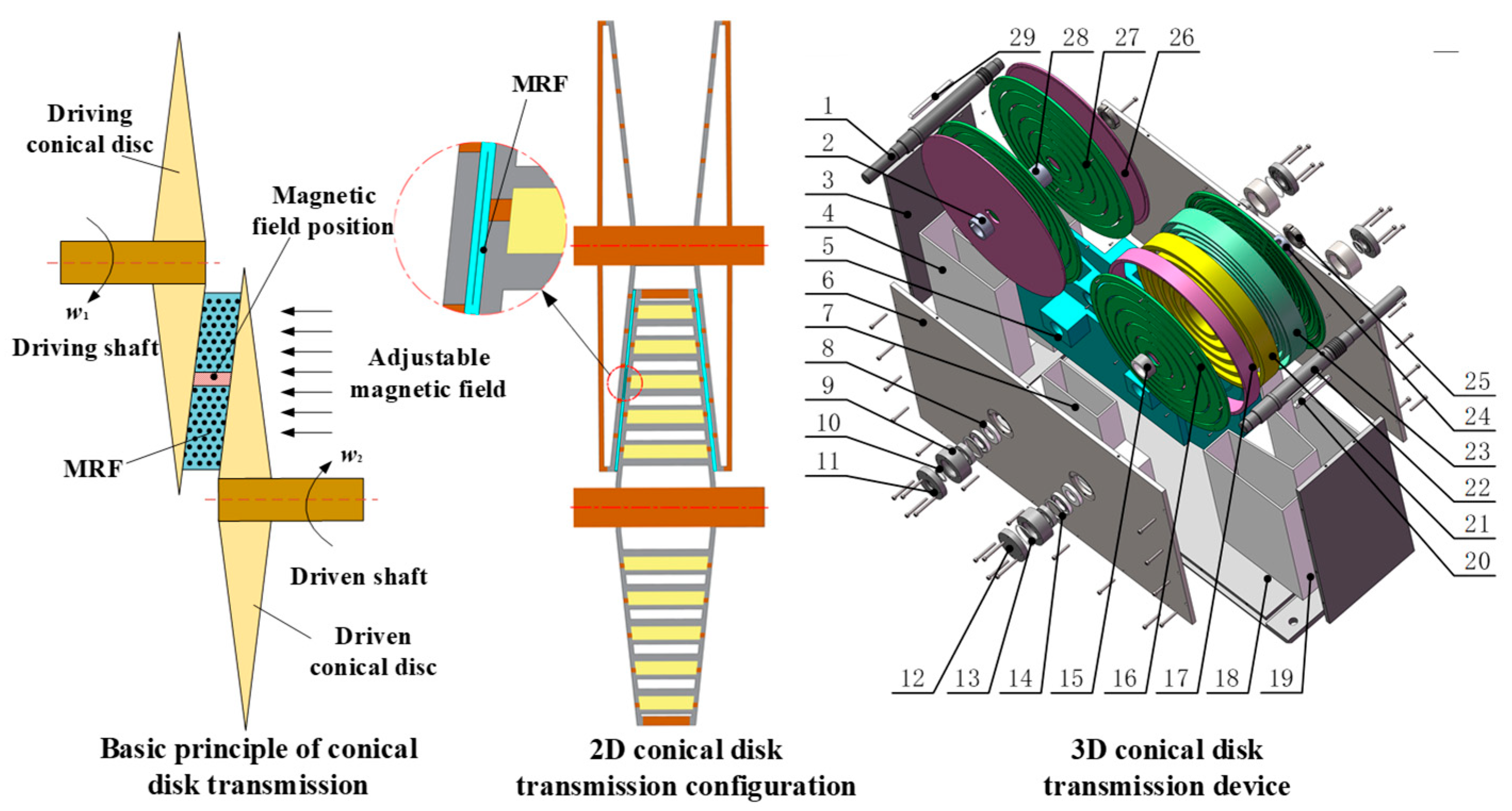
Figure 1. Transmission Model of non-coaxial conical disk MRFTD. 1—Driven shaft; 2, 28, 15, 24—Spacer; 3, 6, 18—Outer shell; 4, 7, 19—Filling cavity; 5—MRF; 8—Skeleton oil seal; 9—Bearing housing; 10, 13—Sealing ring; 11, 12—Bearing end cover; 14—Bearing retaining ring; 16—Conical surface of the driving conical disk; 17—Driving conical disc housing; 20, 29—Key; 21—Multi-stage copper coil; 22—Driving shaft; 23—Multi-stage magnetic conducting ring; 25—Lock nut; 26—Driven conical disc circular surface; 27—Conical surface of the driven conical disk.
Applsci 15 09262 g001
Figure 2. Schematic diagram of transmission between a single set of conical disks.
Applsci 15 09262 g002
Figure 3. Magnetic Circuit Structure Diagram of non-coaxial conical disk MRFTD.
Applsci 15 09262 g003
Figure 4. Equivalent magnetic resistance diagram of MRFTD.
Applsci 15 09262 g004
Figure 5. Simplified model for electromagnetic field analysis.
Applsci 15 09262 g005
Figure 6. Material of the Simulation Model.
Applsci 15 09262 g006
Figure 7. Mesh generation: (a) Mesh generation and mesh quality histogram; (b) Magnetic intensity corresponding to different numbers of mesh cells.
Applsci 15 09262 g007
Figure 8. Magnetic field line distribution: (a) First-stage coil; (b) Second-stage coil; (c) Third-stage coil; (d) Fourth-stage coil; (e) Fifth-stage coil.
Applsci 15 09262 g008
Figure 9. Magnetic flux density distribution: (a) First-stage coil; (b) Second-stage coil; (c) Third-stage coil; (d) Fourth-stage coil; (e) Fifth-stage coil.
Applsci 15 09262 g009
Figure 10. 3D magnetic density of MRF working area: (a) First-stage coil; (b) Second-stage coil; (c) Third-stage coil; (d) Fourth-stage coil; (e) Fifth-stage coil.
Applsci 15 09262 g010
Figure 11. Magnetic induction intensity curve of working area.
Applsci 15 09262 g011
Figure 12. Different currents: (a) 2.2 A; (b) 2.4 A; (c) 2.6 A; (d) Magnetic induction intensity under different currents.
Applsci 15 09262 g012
Figure 13. Different working gap: (a) 1.0 mm; (b) 1.5 mm; (c) 2.0 mm; (d) Magnetic induction intensity under different working gap.
Applsci 15 09262 g013
Figure 14. Different conical angles of the disc: (a) 3°; (b) 6°; (c) 9°; (d) 12°; (e) Magnetic induction intensity under different conical disc base angles.
Applsci 15 09262 g014
Figure 15. Magnetic induction intensity distribution of MRF: (a) 3°; (b) 6°; (c) 9°; (d) 12°.
Applsci 15 09262 g015
Figure 16. Different magnetic conductive materials: (a) DT4C; (b) 20 Steel; (c) 45 Steel; (d) Magnetic induction intensity under different magnetic conductive materials.
Applsci 15 09262 g016
Figure 17. Experiment system.
Applsci 15 09262 g017
Figure 18. Magnetic field intensity characteristics: (a) Not powered; (b) First-stage coil powered; (c) Second-stage coil powered; (d) Third-stage coil powered; (e) Fourth-stage coil powered; (f) Five-stage coil powered.
Applsci 15 09262 g018
Figure 19. Magnetic field intensity characteristic curve.
Applsci 15 09262 g019
Figure 20. Transmission characteristic.
Applsci 15 09262 g020
Figure 21. Torque response characteristics: (a) First-stage coil; (b) Second-stage coil; (c) Third-stage coil; (d) Fourth-stage coil; (e) Fifth-stage coil.
Applsci 15 09262 g021
Figure 22. Temperature characteristics.
Applsci 15 09262 g022
Table 1. Parameters of mesh.
ComponentParameter
Mesh vertex820,744
Number of mesh cells3,397,902
Minimum mesh cell mass0.04918
Average mesh cell mass0.6694
Unit volume ratio6.465 × 10−5
Mesh volume175,900 mm3
Table 2. Parameters of main components.
ComponentParameter
MRF-G28Shear yield stress (0.5 T) ≥ 35 kPa
Temperature range: −40–140 °C
Zero-field viscosity: 0.28 Pa·s
Torque/speed sensorModel: JN-DN
Accuracy: ±0.3%
Torque range: ±100 N·m
Torque/speed transmitterModel: BSQ-12-100 NM
Output signal: 0–±5 V
Working voltage: 24 VDC
GaussmeterModel: CH-1500
Measurement range: 0–3 tons
Resolution: 0.01 mT
NI acquisitionModel: USB-6001
Number of channels: 8
Output range: ±10 V
Disclaimer/Publisher’s Note: The statements, opinions and data contained in all publications are solely those of the individual author(s) and contributor(s) and not of MDPI and/or the editor(s). MDPI and/or the editor(s) disclaim responsibility for any injury to people or property resulting from any ideas, methods, instructions or products referred to in the content.