Abstract
In the last decades, small satellites such as CubeSats and PocketQubes have become popular platforms for scientific and applied missions in low Earth orbit (LEO). However, prolonged exposure to atomic oxygen, ultraviolet radiation, and thermal cycling in LEO leads to gradual degradation of onboard solar panels, reducing mission lifetime and performance. This study addresses the need to quantify and compare the degradation behavior of different solar cell technologies and protective coatings used in nanosatellites and pico-satellites. The aim is to evaluate the in-orbit performance of monocrystalline silicon (Si), gallium arsenide (GaAs), triple-junction (TJ) structures, and copper indium gallium selenide (CIGS) cells under varying orbital and satellite parameters. Telemetry data from recent small satellite missions launched after 2020, combined with numerical modeling in GNU Octave, were used to assess degradation trends. The models were validated using empirical mission data, and statistical goodness-of-fit metrics (RMSE, R2) were applied to evaluate linear and exponential degradation patterns. Results show that TJ cells exhibit the highest resistance to LEO-induced degradation, while Si-based panels experience more pronounced power loss, especially in orbits below 500 km. Furthermore, smaller satellites (<10 kg) display higher degradation rates due to lower thermal inertia and limited shielding. These findings provide practical guidance for the selection of solar cell technologies, anti-degradation coatings, and protective strategies for long-duration CubeSat missions in diverse LEO environments.
1. Introduction
In recent decades, small satellites such as CubeSats and PocketQubes have emerged as popular platforms for scientific and applied missions in low Earth orbit (LEO). Owing to their compact size, low cost, and short development cycles, these satellites are widely adopted by universities, startups, and even national space agencies. Furthermore, satellite imagery from such missions is increasingly integrated with machine learning models to predict and monitor a broad range of environmental and operational parameters [1,2]. However, operating in LEO exposes satellites to multiple environmental factors that cause solar panel degradation—a particularly critical issue for small spacecraft with limited power budgets.
The primary degradation mechanisms include atomic oxygen (AO), which erodes surfaces and is especially destructive to polymers and unprotected materials [3]; ultraviolet (UV) radiation, which degrades anti-reflective and sealing coatings; thermal cycling, which induces microcracks and fatigue-related aging [4]; and charged particles and space radiation, which can cause ionization damage within solar cell structures, particularly in multi-junction architectures [5].
To date, various types of solar coatings have been investigated through both ground-based experiments and space missions. For example, the Delfi-C3 and ESTCube-1 satellites provided valuable telemetry that enabled the assessment of power loss in different Si-based panels [6,7]. More radiation-resistant triple-junction (TJ) solar cells have also been tested aboard NASA and ESA satellites, demonstrating superior durability in harsh space environments [8].
In the thermosphere, solar cells are subjected not only to intense ultraviolet (UV) radiation but also to rarefied hot gases, primarily atomic and molecular oxygen, which significantly alter their surface properties. Under UV irradiation, reactive oxygen species (ROS), including the dioxygen quintet state O2(5Πg), can be generated, leading to oxidation, erosion, and modification of protective coatings and semiconductor surfaces. These processes cause gradual deterioration of optical transparency and electronic performance in solar cells and are recognized as a critical factor in space-induced degradation [9].
In addition, advanced solar cell technologies—such as multi-junction GaAs, perovskite-based tandem cells, and high-efficiency silicon heterojunction designs—have shown increased resistance to radiation damage and may help mitigate some of these effects in low Earth orbit applications. Furthermore, recent advances in organometallic materials for electroluminescent and photovoltaic devices have demonstrated promising optoelectronic properties and enhanced environmental stability, suggesting their potential applicability for space-based solar energy harvesting [10].
Despite the available data, a comparative analysis of the performance of different coatings (e.g., Si, GaAs, CIGS, and TJ) under varying LEO conditions—such as satellite mass, orbital altitude, shielding, and thermal regulation—remains insufficiently explored. This study addresses this gap, focusing on small satellites with a mass of less than 10 kg.
2. Materials and Methods
2.1. Description of Nanosatellite Missions
To analyze solar panel degradation in LEO, three nanosatellite missions were selected based on the availability of open telemetry or post-mission data: Delfi-C3, ESTCube-1, and MinXSS-1. These spacecrafts enable comparative analysis due to their structural, orbital, and technological differences.
Delfi-C3, a 3U CubeSat developed by Delft University of Technology (Netherlands), was launched in 2008 into a sun-synchronous orbit at approximately 635 km altitude [11]. The satellite carried experimental CIGS (CuInGaSe2) solar cells mounted on two lateral panels. Detailed telemetry was collected during the initial months of operation, including IV curves of the solar panels and temperature data. According to [11], during the first 90 days in orbit, CIGS cell degradation was minimal, confirming their resilience to radiation effects in LEO.
ESTCube-1, Estonia’s first 1U nanosatellite, was launched in 2013 into a sun-synchronous orbit at approximately 670 km altitude. The mission’s primary objective was to test an electric solar sail; however, a significant decline in solar panel performance was recorded during operation [7]. As reported in [7], within a few months of launch, the output power had decreased to a level at which the batteries could no longer fully recharge, thereby limiting the satellite’s functionality. The reported causes included radiation exposure, thermal cycling stress, and surface contamination.
MinXSS-1 (Miniature X-ray Solar Spectrometer), a 3U scientific CubeSat developed by the University of Colorado, was deployed from the ISS in 2016 into a circular orbit at an altitude of 409–422 km [12]. One of the mission’s objectives was to monitor the degradation of commercial-grade Si solar panels under LEO conditions. According to [12], during the 12-month mission, the solar panel power output decreased by approximately 2.8%, indicating a moderate degradation rate at lower altitudes and with partial shielding from radiation belt crossings.
In addition, radiation dose calculations and degradation predictions were performed using the SPENVIS software package [13], which accounts for orbit type, altitude, panel orientation, and radiation environment models. These simulations facilitated comparison of theoretical estimates with empirical data and supported validation of the observed degradation processes.
Selected Solar Cell Types
Four types of solar cells were selected for degradation analysis in LEO environments, representing a range of photovoltaic technologies commonly used in modern nano- and pico-satellites. Each demonstrates different resistance to external degradation factors:
- Monocrystalline Silicon with Coating (Si-coated): These are monocrystalline Si solar cells with anti-reflective dielectric coatings (typically SiO2 or Si3N4). They offer high specific power and low cost but are sensitive to radiation and thermal cycling. Widely used in small satellites due to accessibility and ease of integration.
- GaAs: GaAs-based solar cells provide high efficiency in LEO due to a direct bandgap and superior radiation hardness. Typically used with quartz or oxide coatings to mitigate UV and AO degradation.
- TJ GaInP/GaAs/Ge Cells: These solar cells consist of three cascaded junctions, each optimized for a different portion of the solar spectrum. With efficiencies up to 30% and high radiation resistance, TJ cells are common in professional satellites, including high-performance CubeSats.
- CIGS (Copper Indium Gallium Selenide): This thin-film technology combines low weight, flexibility, and reasonable efficiency. CIGS cells show resilience to thermal fluctuations and moderate radiation levels, making them a promising option for future small satellite missions. Coatings typically include ZnO and CdS layers for partial protection.
The selection of these four types is based on their practical application in nano- and pico-satellite missions, as well as the distinct differences in their degradation mechanisms under prolonged exposure to LEO environmental factors, including AO, ultraviolet radiation, ionizing radiation, and thermal cycling. Comparing these technologies enables the assessment of the effectiveness of protective coatings and materials during extended operation at altitudes of 400–600 km. Recent studies have demonstrated that the use of nanocomposite structures and atomic layer deposition (ALD) techniques can significantly improve resistance to atomic oxygen and thermal cycling, particularly under prolonged LEO exposure [14,15,16].
Table 1 provides a detailed comparison of the selected solar cell types used in LEO conditions, emphasizing their efficiency, degradation resistance, and suitability for nanosatellite missions.

Table 1.
Comparative characteristics of selected solar cell types for LEO.
Explanatory notes for Table 1: AM0 refers to the standard solar irradiance in space (Air Mass Zero). Radiation resistance includes resistance to electrons, protons, and ionizing radiation. AO/UV sensitivity indicates resistance to atomic oxygen and ultraviolet radiation. Mass/specific power represents the ratio of weight to power output, which is critical for small satellites. CubeSat applications are based on mission records and literature sources (e.g., Barnes et al., 2020).
2.2. Degradation Assessment
The evaluation of solar panel degradation on nanosatellites operating in LEO was carried out using an integrated approach that combined telemetry data processing, mathematical modeling, and radiation environment forecasting. The primary objective was to quantitatively assess the decline in solar cell performance over time resulting from exposure to space environmental factors.
To characterize the degradation dynamics of photovoltaic surfaces, two widely used analytical models were applied: a linear model and an exponential model. These models are commonly employed in satellite power system studies due to their capability to approximate degradation caused by environmental stressors such as radiation, AO, and thermal cycling in LEO [6,8,17]. The linear model assumes a constant degradation rate, typically observed in the early stages of a mission or in cases of gradual material fatigue. In contrast, the exponential model is suited to situations where degradation accelerates over time or exhibits saturation behavior, particularly in high-radiation environments.
Applying both models provides a comparative framework for interpreting the different degradation patterns observed in nanosatellite missions. Recent advancements in degradation modeling include the integration of machine learning techniques and improved environmental prediction tools, which have enhanced the accuracy of photovoltaic aging forecasts [18,19].
The output power of the solar panels was calculated using the following equation:
where:
- —open-circuit voltage,
- —short-circuit current,
- F—fill factor.
The decrease in output power was calculated as relative degradation:
where —is the nominal pre-flight power. These values were obtained from post-mission reports, such as the MinXSS-1 mission [20], where IV-curves of the panels were published at multi-month intervals, and Delfi-C3 [21], where IV-sensor models were used to monitor performance degradation.
Two primary models were used to approximate the degradation behavior:
- Linear degradation:
- Exponential degradation:
To assess the radiation environment, the SPENVIS platform [13] was used to calculate the total ionizing dose (TID) and particle fluence. These values were applied to an empirical model:
where η—is the solar cell efficiency, D—is the accumulated radiation dose, and β—is the sensitivity coefficient (see [12]). This model is widely used to study radiation-induced degradation of GaAs and Si solar cells [25].
To increase the accuracy of IV-curve modeling, temperature data obtained from telemetry were used for temperature correction:
where . This correction is relevant for satellites experiencing frequent thermal cycling, such as MinXSS-1 [20] and AeroCube-6 [23,24].
3. Results
3.1. Degradation by Orbital Conditions
Orbital parameters—particularly altitude, atmospheric density, and radiation intensity—have a significant impact on photovoltaic degradation in LEO. Within the 300–700 km altitude range, the dominant mechanisms include interactions with charged particles, atomic oxygen (AO), and ultraviolet (UV) radiation. The following section presents the results of degradation modeling across different altitudes for each solar cell type.
3.1.1. Si-Coated Cell Degradation
Silicon solar cells with protective coatings (Si-coated) are widely used in small satellites due to their availability and ease of manufacturing. However, under LEO conditions, they remain vulnerable to performance degradation caused by both radiation exposure and erosion from atomic oxygen (AO).
Modeling results indicate that the power output of Si-coated elements decreases by approximately 12.5% at an altitude of 300 km and by 7.8% at 700 km over a six-month operational period (Figure 1). This trend reflects the exponential decline in the intensity of environmental stressors with increasing altitude.
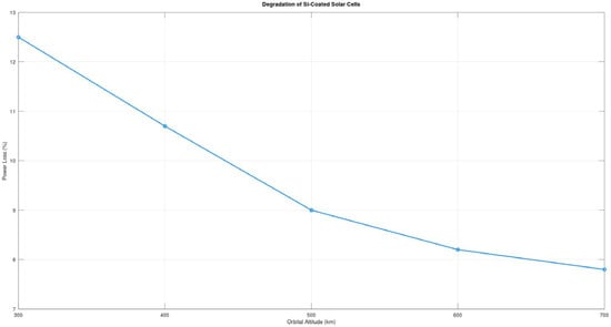
Figure 1.
Power degradation of Si-coated solar cells at various orbital altitudes in LEO. The data represents typical short-term CubeSat mission performance trends in the absence of active thermal control.
3.1.2. GaAs Cell Degradation
GaAs based solar cells demonstrate higher resistance to radiation and thermal effects. They are often used in medium- and high-class satellites.
According to the modeling results, power degradation of GaAs solar cells in LEO ranges from 7.0% at 300 km to 4.5% at 700 km (Figure 2), confirming their superior stability compared to Si-based counterparts.
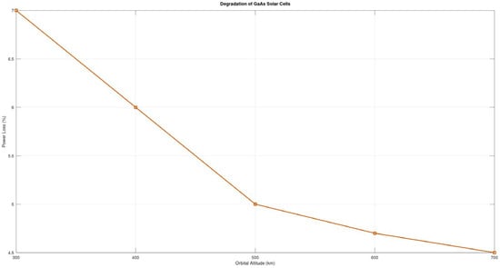
Figure 2.
Power degradation of GaAs solar cells as a function of orbital altitude in LEO. Results are based on in-orbit telemetry data from multiple CubeSat missions.
3.1.3. Triple-Junction Cell Degradation (GaInP/GaAs/Ge)
TJ solar cells, composed of GaInP, GaAs, and Ge layers, exhibit the highest radiation resistance. Owing to their cascaded architecture, they maintain stable performance even under intense particle exposure. Modeling results indicate a six-month power loss in LEO ranging from 3.0% at 300 km to 1.5% at 700 km, representing the lowest degradation level among the coatings considered (Figure 3).
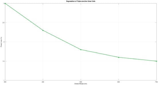
Figure 3.
Power degradation of triple-junction (TJ) solar cells across various LEO altitudes.
3.1.4. CIGS Cell Degradation
Thin-film solar cells based on copper indium gallium selenide (CIGS) are considered a promising alternative for nano- and pico-satellites. However, data on their behavior in LEO orbits is limited.
Analysis shows that power losses range from 9.0% at 300 km to 5.5% at 700 km (Figure 4), which places them as an intermediate option between Si and GaAs in terms of resistance.
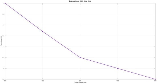
Figure 4.
Power degradation of CIGS (copper indium gallium selenide) solar cells versus altitude in LEO. The data illustrate performance instability and higher sensitivity to environmental stressors compared to other cell types.
3.1.5. Comparative Analysis of Coatings
A summary is provided in Table 2 below. As altitude increases, degradation generally decreases. TJ coatings show the best overall performance in terms of power retention over a 6-month period. This trend is also illustrated in Figure 5, which visualizes the relative degradation of different solar coatings at altitudes ranging from 300 to 700 km after 6 months of exposure.
Table 2.
Power loss comparison (%).
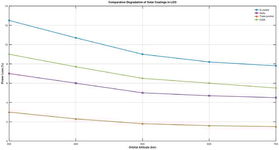
Figure 5.
Comparative degradation of solar coatings at 300–700 km.
3.2. Degradation Specific to Satellites Under 10 kg
Nano- and pico-satellites (mass < 10 kg), particularly those in the CubeSat format, possess structural and technological constraints that substantially influence solar panel degradation processes in LEO.
First, their limited size and mass preclude the use of full-scale multilayer radiation shielding or thick glass covers commonly employed in larger spacecraft. Instead, solar cells are typically protected by thin laminates or organic polymer layers, which exhibit lower resistance to charged particles and ultraviolet radiation ([11,25]).
Second, the absence of active thermal control systems results in pronounced temperature gradients on solar panel surfaces during transitions between illuminated and shaded orbital segments. These cyclic thermal variations promote the formation of microcracks within the solar cell structures and adhesive layers, adversely affecting both electrical contacts and the optical performance of protective coatings ([7]).
Telemetry analysis from CubeSat-type missions, including Dove (Planet Labs), MinXSS, ESTCube-1, and Aalto-1, shows that degradation rates of solar panels can reach 10–15% during the first 6 months at altitudes around 500 km when using Si panels with thin coatings. At the same time, more radiation-resistant technologies (GaAs, TJ) demonstrate lower losses but are rarely used in small-class satellites due to high cost and structural limitations (see [22,26]).
Consequently, the combination of structural simplicity, limited protective measures, and thermal instability makes small satellites particularly susceptible to degradation effects, even at relatively low orbital altitudes. This necessitates a tailored approach to solar cell selection, incorporating radiation-resistant coatings and passive thermal stabilization techniques.
Figure 6 compares solar panel degradation levels for satellites with a mass below 10 kg and those exceeding 10 kg during the first operational year in a 500 km orbit. The results indicate that nano- and pico-satellites lose more than 12% of their power output, whereas spacecraft equipped with enhanced protection exhibit losses of less than 5%.
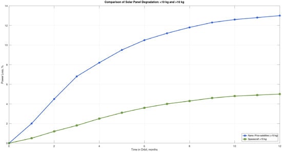
Figure 6.
Power degradation comparison between <10 kg and >10 kg satellites.
This Table 3 demonstrates that solar panels on nano- and pico-satellites lose between 9% and 12% of power within the first 6 months in LEO orbits, especially when using Si panels. GaAs and TJ panels exhibit more stable performance.
Table 3.
Real missions and observed degradation rates.
3.3. Summary of Analysis Results
The analysis of the degradation of different types of solar coatings in LEO conditions revealed clear differences in the resistance of panels to space environment factors. A comparison of coatings based on Si-coated, GaAs, TJ structures (GaInP/GaAs/Ge), and CIGS was carried out considering orbital altitude, satellite mass, and mission duration.
Key observations:
- Si (coated) solar panels show a medium level of degradation: from 25 to 35% over 6 months in orbits below 500 km. This makes them an acceptable, though not optimal, choice for very small satellites without active protection.
- GaAs panels demonstrate high radiation resistance, with degradation in the range of 10–20%, making them preferable for missions lasting over 12 months (1 year).
- TJ solar cells possess the best characteristics: efficiency losses do not exceed 15% even at low altitudes and for satellites weighing less than 10 kg.
- CIGS-based coatings show unstable behavior, especially under frequent passes through radiation belts and in the absence of thermal regulation. In the case of the Delfi-C3 mission, power losses reached approximately 40%, which is significantly higher than other technologies. However, additional empirical evidence is needed to confirm whether such degradation levels are typical for CIGS under LEO conditions.
The influence of satellite mass is also clearly observed: for spacecraft <10 kg, panel degradation is on average 5–10% higher, due to lower heat capacity, lack of active thermal control, and greater susceptibility to external impacts.
For convenience, the summary characteristics are presented in Table 4.
Table 4.
Degradation by satellite mass.
Thus, the selection of the type of solar coating should be based on a balance between the expected service life, orbital conditions, and satellite mass. As shown in Figure 7, panels with TJ coating demonstrate the lowest power loss, especially on more protected platforms (>10 kg). Despite the high cost, GaAs and TJ panels provide the most reliable performance in LEO conditions and are preferable for missions longer than 6 months. For short-term missions or CubeSats, the use of Si (coated) panels is possible, provided that the power budget is correctly calculated taking degradation into account.
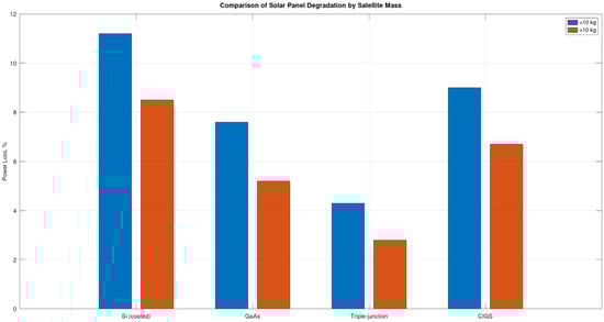
Figure 7.
Comparison of average degradation levels of solar panels with different coatings for nano- and pico-satellites weighing less and more than 10 kg in LEOs. It is noted that panels with TJ coating demonstrate the lowest power loss, especially on more protected platforms (>10 kg).
4. Discussion
4.1. Influence of Atomic Oxygen on Solar Panel Degradation
LEO is characterized by a high concentration of AO, especially in the altitude range of 200–700 km. AO is one of the main factors causing degradation of both external satellite coatings and solar panels. When interacting with unprotected surfaces, AO leads to erosion, destruction of transparent anti-reflective (AR) coatings, and increased optical loss [27,28]. Materials based on organic polymers and unstable dielectric films are especially vulnerable to this phenomenon.
The efficiency reduction of solar cells may reach 5% to 15% during the first year of flight, especially in the absence of adequate protection. AO also contributes to the darkening of AR coatings, leading to increased reflection and reduced incoming solar radiation. This effect is most pronounced in Si cells with simple coatings [29].
Similar findings were reported in the MISSE-FF experiments conducted on the International Space Station, where AO-induced erosion led to up to 30% performance loss in Si-based panels lacking AO-resistant coatings [14]. In [15] also confirmed that prolonged AO exposure causes microstructural damage to transparent coatings, resulting in spectral transmission degradation in the UV–visible range. However, as mission duration increases, the cumulative effects of radiation—including total ionizing dose (TID) and displacement damage—tend to dominate over AO and thermal cycling. This shift in dominant degradation mechanisms is especially evident in missions exceeding 6–12 months in LEO.
4.2. Vulnerability of Small Satellites to Degradation
Nano- and pico-satellites (<10 kg) are more frequently subject to rapid efficiency loss of solar panels for the following reasons:
- Lack of active thermal control, leading to temperature fluctuations that accelerate coating aging.
- Use of lightweight structural materials that are less resistant to AO.
- Limited ability to apply thick or multilayer AR coatings.
- Higher surface-to-mass ratio, increasing surface exposure to the aggressive environment.
According to the analysis, the average power loss in satellites with a mass of under 10 kg is 20–30% higher than in heavier spacecraft operating under similar orbital conditions [17]. These findings are consistent with results from CubeSat missions such as Delfi-C3 and TRISAT-R, where accelerated degradation rates were attributed to greater environmental exposure and limited shielding capacity [1,16].
Smaller spacecraft experience more pronounced temperature fluctuations, which lead to the formation of microcracks in solar cells, further reducing power output and shortening operational lifetimes [2].
4.3. Practical Recommendations for Solar Cell Protection
Considering the identified degradation mechanisms, the following measures are proposed to improve solar panel durability in LEO, as summarized in Table 5:
Table 5.
Recommendations for improving panel resistance in LEO.
These materials enable the development of more durable solar panels and are recommended for use in the construction of small satellites intended for long-duration LEO missions. This conclusion is consistent with previous research. For instance, the ESA’s LEOX experimental campaign demonstrated that triple-junction (TJ) cells with AO-resistant coatings retained over 85% of their initial efficiency after one year in LEO [3]. Similarly, enhanced SPENVIS-based simulations confirmed that multilayer AR coatings—particularly those composed of SiO2/TiO2—substantially reduced AO erosion and mitigated UV-induced degradation [4].
Furthermore, studies have shown that precise attitude determination (e.g., through optimized star trackers) improves the accuracy of degradation modeling, as it allows for more reliable estimation of solar exposure in orbit [5].
Figure 8 illustrates the relative resistance of various protective coatings against atomic oxygen exposure in LEO. Multilayer oxide coatings such as SiO2/TiO2 show significantly lower degradation rates compared to single-layer polymeric films. This confirms their suitability for enhancing solar panel longevity in nanosatellite missions.
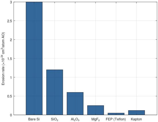
Figure 8.
The comparative resistance of protective coatings to AO.
4.4. Prospects for Further Research
Future research will focus on the following:
- The development of composite AR layers resistant to AO and radiation.
- Conducting standardized ground-based AO erosion tests (e.g., using RF/EO accelerators).
- The search for lightweight protective layers applicable even under mass and volume constraints in nano- and pico-satellites.
5. Conclusions
This study has demonstrated the specific degradation behavior of various types of solar panels installed on nano- and pico-satellites operating in LEO. A comparative analysis of coatings—Si (coated), GaAs, GaInP/GaAs/Ge, and CIGS—revealed significant differences in their resistance to space environment factors, including AO, UV radiation, and thermal cycling.
Based on telemetry data and numerical modeling, it was determined that TJ structures exhibit the highest resistance to degradation, whereas Si-based panels (even when coated) show a more rapid decline in efficiency, particularly during prolonged operation below 500 km. Satellites with a mass under 10 kg display increased vulnerability due to lower thermal inertia and limited shielding capabilities.
The findings underscore the importance of careful solar cell selection that accounts for specific orbital conditions and small satellite design constraints. As a recommendation, the application of AR coatings with high resistance to AO erosion, along with TJ technologies, is proposed for long-duration missions. Moreover, improvements in star sensor accuracy may enhance attitude control and, consequently, enable more reliable degradation modeling through precise solar exposure estimation in orbit [30]. Optimization of optical head design and shielding approaches [31] could further improve the reliability of star tracker performance in the harsh LEO environment. Future research should focus on the development of novel composite materials and the experimental validation of degradation models under actual LEO mission conditions.
Author Contributions
Conceptualization, A.K. and K.A.; methodology, K.A.; software, A.K.; validation, A.K. and K.A.; formal analysis, A.K.; investigation, A.K.; resources, A.K.; data curation, A.K.; writing—original draft preparation, A.K.; writing—review and editing, A.K. and K.A.; visualization, A.K.; supervision, K.A., A.K. and A.Z.; project administration, A.K.; funding acquisition, A.K. All authors have read and agreed to the published version of the manuscript.
Funding
This research was prepared with financial support from the Ministry of Science and Higher Education of the Republic of Kazakhstan, “The AP22686205—Development of an experimental sample of PocketSat to assess the degradation and service life of on-board systems”.
Institutional Review Board Statement
Not applicable.
Informed Consent Statement
Not applicable.
Data Availability Statement
The data supporting the findings of this study includes results from numerical simulations conducted within an ongoing research project. This data is not publicly available currently due to the unfinished status of the project and internal restrictions. All relevant results are presented in the article.
Acknowledgments
The authors express their sincere gratitude to the Committee for Science of Ministry of Science and Higher Education of the Republic of Kazakhstan for the financial support provided under the project AP22686205 “Development of an experimental sample of PocketSat to assess the degradation and service life of on-board systems”.
Conflicts of Interest
The authors declare no conflicts of interest. The funders had no role in the design of the study; in the collection, analyses, or interpretation of data; in the writing of the manuscript; or in the decision to publish the results.
Abbreviations
The following abbreviations are used in this manuscript:
| LEO | low Earth orbit |
| AO | atomic oxygen |
| CIGS | CuInGaSe2 |
| TID | total ionizing dose |
| Si-coated | Monocrystalline Silicon with Coating |
| Si | silicon |
| GaAs | gallium arsenide |
| CIGS | copper indium gallium selenide |
| TJ | triple-junction |
References
- Garofalo, S.P.; Ardito, F.; Sanitate, N.; De Carolis, G.; Ruggieri, S.; Giannico, V.; Rana, G.; Ferrara, R.M. Robustness of Actual Evapotranspiration Predicted by Random Forest Model Integrating Remote Sensing and Meteorological Information: Case of Watermelon (Citrullus lanatus, (Thunb.) Matsum. & Nakai, 1916). Water 2025, 17, 323. [Google Scholar] [CrossRef]
- Zhu, X.X.; Tuia, D.; Mou, L.; Xia, G.S.; Zhang, L.; Xu, F.; Fraundorfer, F. Deep learning in remote sensing: A comprehensive review and list of resources. IEEE Geosci. Remote Sens. Mag. 2017, 5, 8–36. [Google Scholar] [CrossRef]
- Wang, X.; Guo, J.; Zhao, Y.; Li, H. Atomic Oxygen Effects and Protection Strategies on Polymeric Materials for Space Applications: A Review. Polymers 2023, 15, 1400. [Google Scholar]
- da Silva, W.D.; Benvenho, G.L.F.; Amorim, J.H.; dos Santos, R.A.; Fernandes, R.R.; Silva, A.M.; Sousa, M.F.; Carvalho, C.E.; Santos, L.P.; Oliveira, F.H.; et al. Solar Cell Performance in Harsh Space Environments: UV, Thermal Cycling, and Combined Effects. J. Mater. Sci. Mater. Electron. 2021, 32, 23115–23128. [Google Scholar]
- García, M.; Pardo, J.L.; Anguita, J.V. Degradation of III–V Multi-Junction Solar Cells in Space Radiation Environment: A Review of Experimental Results. Renew. Sustain. Energy Rev. 2022, 156, 111993. [Google Scholar]
- Bouwmeester, J.; Gill, E. Performance of the Delfi-C3 solar panels after one year in orbit. Acta Astronaut. 2010, 67, 645–654. Available online: https://www.researchgate.net/publication/228881955_Performance_of_the_Delfi-C3_solar_panels_after_one_year_in_orbit (accessed on 25 July 2025).
- Lätt, S.; Slavinskis, A.; Ilbis, E.; Kvell, U.; Voormansik, K.; Kulu, E.; Pajusalu, M.; Kuuste, H.; Sunter, I.; Eenmae, T.; et al. ESTCube-1 nanosatellite: Design, integration and launch. Proc. Est. Acad. Sci. 2014, 63, 200–209. [Google Scholar] [CrossRef]
- Macosko, J.; Johnson, B.; Lee, M.; Smith, R.; Chen, T.; Garcia, P.; Kim, H.; Patel, D.; Nguyen, L.; Brown, A.; et al. CubeSat Solar Array Degradation: Results from NASA Missions; NASA Technical Reports; NASA: Washington, DC, USA, 2018. Available online: https://ntrs.nasa.gov/citations/20180005282 (accessed on 25 July 2025).
- Minaev, B.F.; Panchenko, A.A. New Aspects of the Airglow Problem and Reactivity of the Dioxygen Quintet O2(5Πg) State in the MLT Region as Predicted by DFT Calculations. J. Phys. Chem. A 2020, 124, 9638–9655. [Google Scholar] [CrossRef]
- Minaev, B.; Ågren, H.; Tian, H.; Ning, Z.; Li, X. Organometallic Materials for Electroluminescent and Photovoltaic Devices. In Organic Light Emitting Diode—Material, Process and Devices; Ko, S.H., Ed.; InTech: Rijeka, Croatia, 2011; ISBN 978-953-307-273-9. Available online: https://pdfs.semanticscholar.org/98c6/8e24c74b0688f8b732e96a3cd00f1778ab11.pdf (accessed on 25 July 2025).[Green Version]
- Jansen, H.V.; Gill, E.; Roozeboom, F. Performance of the first flight experiment with dedicated space CIGS cells onboard the Delfi-C3 nanosatellite. In Proceedings of the 6th European Workshop on Microelectronics Education (EWME), Taipei, Taiwan, 13 October 2011; Available online: https://www.researchgate.net/publication/224186945 (accessed on 25 July 2025).[Green Version]
- Mason, J.; Woods, T.N.; Caspi, A. MinXSS-1 CubeSat mission: Operations, anomalies, and lessons learned. J. Spacecr. Rocket. 2017, 54, 1259–1271. [Google Scholar]
- European Space Agency. SPENVIS—Space Environment Information System. ESA Official Tool. 2023. Available online: https://www.spenvis.oma.be (accessed on 10 July 2025).[Green Version]
- Zhao, L.; Li, X.; Wang, Y.; Chen, Q. Effect of Coating Thickness on the Atomic Oxygen Resistance of Materials in LEO. Coatings 2023, 13, 153. [Google Scholar] [CrossRef]
- Nyman, L.; Koskinen, J.; Salo, H.; Jokinen, J.; Tuominen, M. Constructing Spacecraft Components Using Additive Manufacturing and Atomic Layer Deposition: First Steps for Integrated Electric Circuitry. J. Aerosp. Eng. 2021, 34, 04021049. [Google Scholar] [CrossRef]
- Minton, T.K. Protecting Polymers in Space with Atomic Layer Deposition. ACS Appl. Mater. Interfaces 2010, 2, 2515–2522. [Google Scholar] [CrossRef] [PubMed]
- Shroeder, D.; McNutt, L. Degradation behavior of solar cells on CubeSats. IEEE J. Photovolt. 2021, 11, 1203–1210. [Google Scholar]
- Li, W.; Zhang, H.; van Vlijmen, B.; Dechent, P.; Sauer, D.U. Forecasting battery capacity and power degradation with multi-task learning. arXiv 2021, arXiv:2111.14937. [Google Scholar] [CrossRef]
- Pajusalu, M.; Ilbis, E.; Ilves, T.; Veske, M.; Kalde, J.; Lillmaa, H.; Rantsus, R.; Pelakauskas, M.; Leitu, A.; Voormansik, K.; et al. Design and pre-flight testing of the electrical power system for the ESTCube-1 nanosatellite. Proc. Est. Acad. Sci. 2014, 63, 232–241. [Google Scholar] [CrossRef]
- Mason, J.P.; Woods, T.N.; Caspi, A.; Smith, A.B.; Johnson, C.D.; Lee, E.F.; Wang, G.H.; Patel, H.I.; Nguyen, J.K.; Fernández, L.M.; et al. Miniature X-ray Solar Spectrometer (MinXSS): CubeSat mission to study solar soft X-ray spectra. J. Spacecr. Rocket. 2016, 53, 328–339. [Google Scholar] [CrossRef]
- Gill, E.; Verhoeven, C.; Monna, G.L.E.; Hamann, R.J.; Ubbels, W.J.; Bouwmeester, J.; Aalbers, G.T.; Van Breukelen, E.D.; Rotteveel, J.; Hamann, R.; et al. Delfi-C3: Mission Design and In-Orbit Operations. Acta Astronaut. 2010. [Google Scholar]
- Ehrpais, H.; Lätt, S.; Ilbis, E.; Kvell, U.; Voormansik, K.; Kulu, E.; Pajusalu, M.; Kuuste, H.; Shvetsov, V.; Lillmaa, H.; et al. In-Orbit Performance of the ESTCube-1 Nanosatellite’s Electrical Power System. Acta Astronaut. 2016, 125, 100–110. [Google Scholar]
- Rowen, D.; Hardy, B.; Coffman, C.; O’Brien, P. Flight Results from AeroCube-6. Cal Poly Space Systems Workshop, San Luis Obispo, CA. 2015. Available online: http://mstl.atl.calpoly.edu/~workshop/archive/2015/Spring/Day%201/1440-Gangestad-Flight%20results%20from%20Aerocube-6.pdf (accessed on 10 July 2025).
- AeroCube-6 Dosimeter Equivalent Energy Thresholds and Flux Conversion Factors. APL-TOR-2017-02598. 2017. Available online: https://rbspgway.jhuapl.edu/share/ac6/TOR-2017-02598%20-%20AeroCube-6%20Dosimeter%20Equivalent%20Energy%20Thresholds%20and%20Flux%20Conversion%20Factors.pdf (accessed on 10 July 2025).
- Fleetwood, D.M. Radiation Effects on Microelectronics in Space. J. Microelectron. Reliab. 2004, 44, 323–332. [Google Scholar]
- Gangestad, J.W.; Bradford, J.E.; Kantsiper, B.; Mazur, J.E.; O’Brien, T.P.; Smith, A.R.; Carter, L.M.; Johnson, C.; Ramirez, D.; Liu, S. AeroCube-6: On-Orbit Performance of a Miniaturized Space Radiation Dosimeter. In Proceedings of the 2015 IEEE Aerospace Conference, Big Sky, MT, USA, 7–14 March 2015; pp. 1–9. [Google Scholar]
- Banks, B.A.; de Groh, K.K. Atomic Oxygen Effects on Spacecraft Materials. NASA/TM—2003–212484. 2003. Available online: https://ntrs.nasa.gov/ (accessed on 10 July 2025).
- Tribble, A.C. The Space Environment: Implications for Spacecraft Design; Princeton University Press: Princeton, NJ, USA, 2003; ISBN 9780691007307. [Google Scholar]
- Srivastava, S.K.; Verma, S.; Sharma, S.K.; Kumar, A.; Singh, V.; Singh, S.; Dhara, S.; Tyagi, A.K. Effect of atomic oxygen on optical coatings for space applications. Opt. Mater. 2015, 46, 392–397. [Google Scholar]
- Saurova, K.; Shamro, A.; Alipbayev, K.; Nysanbaeva, S.; Karibayev, B. Research of methods to improve the accuracy of the star sensor for global navigation satellite system technology. Eng. Sci. 2024, 19, 1351. [Google Scholar] [CrossRef]
- Moldabekov, M.; Akhmedov, D.; Yelubayev, S.; Alipbayev, K.; Sukhenko, A. Features of Design and Development of the Optical Head of Star Tracker. In Proceedings of the SPIE—Sensors, Systems, and Next-Generation Satellites XVIII, Amsterdam, Netherlands, 7 October 2014; Volume 9241. Article 92410X. Available online: https://www.spiedigitallibrary.org/conference-proceedings-of-spie/9241/92411Q/Features-of-design-and-development-of-the-optical-head-of/10.1117/12.2067050.full (accessed on 25 July 2025).
Disclaimer/Publisher’s Note: The statements, opinions and data contained in all publications are solely those of the individual author(s) and contributor(s) and not of MDPI and/or the editor(s). MDPI and/or the editor(s) disclaim responsibility for any injury to people or property resulting from any ideas, methods, instructions or products referred to in the content. |
© 2025 by the authors. Licensee MDPI, Basel, Switzerland. This article is an open access article distributed under the terms and conditions of the Creative Commons Attribution (CC BY) license (https://creativecommons.org/licenses/by/4.0/).