1. Introduction
Ultrasonic sensing (US) is a key technology in modern automotive systems, enabling applications such as parking assistance, obstacle avoidance, and autonomous navigation. Conventional ultrasonic sensors, based on bulk piezoelectric transducers, are constrained by several limitations: restricted bandwidth, fixed beam angles, large form factors, and limited integration with on-chip signal processing. These constraints reduce spatial resolution and system scalability, making them less suitable for emerging autonomous platforms that require high-resolution, low-latency, and wide-area environmental awareness. In advanced driver assistance systems (ADAS), ultrasonic sensors play a vital role in short-range applications such as parking assistance, blind-spot detection, collision avoidance, and proximity sensing. Their low power consumption, low cost, and non-line-of-sight capability make them indispensable, especially when integrated with CMOS platforms for automotive-grade reliability. The proposed CMUT-CMOS solution enhances these capabilities by enabling beamforming-based angle control and reducing blind zones without increasing system complexity.
Recent advancements in sensor technology are addressing limitations of conventional ultrasonic systems for automotive and robotic applications. A compact on-chip mm-wave reconfigurable wideband filtering switch in 28-nm CMOS enables integrated sensing and communication with tunable passband frequencies [
1]. For 5G vehicular applications, a low-profile mm-wave planar phased array antenna with wide spatial coverage and beam-scanning capabilities has been developed [
2]. In human-robot collaboration, various sensor technologies, including IR-structured light, capacitive, LiDAR, and stereo cameras, were integrated to enhance safety systems [
3]. A novel metasurface-assisted ultrasound positioning system transforms ordinary speakers into directional sound sources, allowing microrobots with simple microphones to determine their location accurately in GPS-denied environments [
4]. These innovations collectively address challenges in spatial resolution, form factor, and integration with signal processing for autonomous platforms. CMOS-compatible-US has emerged as a compelling alternative to traditional piezoelectric transducers due to their wide bandwidth and high-frequency operation.
Unlike piezoelectric sensors, capacitive micromachined ultrasonic transducer (CMUT) enables monolithic integration of the transducer array with control and signal processing electronics on a single chip, significantly reducing size and power consumption while improving system performance [
5]. Recent advancements in ultrasonic transducer technology have led to improved performance and novel applications. Piezoelectric micromachined ultrasonic transducers (PMUT) have been developed for noncontact human-machine interaction, enabling air-writing recognition with high accuracy [
6]. A new (1A,1B)-3 piezocomposite structure has demonstrated enhanced bandwidth and sensitivity compared to conventional designs [
7]. For capacitive MEMS microphones, a nonlinear behavioural model has been proposed to predict and minimise ultrasound intermodulation distortion, crucial for hearing aid applications [
8]. A
discretised hyperbolic paraboloid CMUT array operating at 40 kHz with a 40° beamwidth and
sidelobes was fabricated using SOI technology, incorporating a non-planar PGA-68 package and a novel analytical model for square diaphragm deflection and fringing capacitance estimation [
9]. These innovations showcase the ongoing progress in ultrasonic transducer technology across various domains. Beamforming technology implementation in automotive vehicles may shape the future of communication systems. As the RF beamformer ideas have been discussed in detail here [
10,
11,
12,
13], these papers highlighted the ISAC and its importance, and each component’s role in the transmitter, like the phase shifter (PS) and variable gain amplifier (VGA).
In this work, a CMOS-compatible two-dimensional array is integrated with programmable transmit (TX) and receive (RX) beamformers to realise a fully electronic, solid-state ultrasonic sensing architecture. The system is architected to provide omnidirectional azimuthal and full vertical beam coverage without the use of mechanical scanning components. Steering and focusing of acoustic energy are achieved via digitally controlled delay-and-sum beamforming, in which element-specific time delays are modulated according to directional steering parameters. The transmit beamformer synthesises controlled wavefronts by introducing calculated temporal offsets across the array, while the receive beamformer temporally aligns incoming echoes based on their time of flight corresponding to predefined spatial angles. The delay configuration for each array element is dynamically generated by a beam-control logic unit, which interprets input steering angles to enable real-time adaptive beam steering. This paper presents a comprehensive theoretical formulation of the proposed beamforming system, including its architectural and operational principles and signal processing strategies. The analysis establishes the feasibility of achieving electronically steerable, high-resolution acoustic imaging using ultrasound sensor (US) arrays monolithically integrated with CMOS electronics. Such a configuration enables compact, low-power, and high-performance ultrasonic sensor modules, ideally suited for deployment in advanced autonomous platforms and next-generation driver-assistance systems.
2. Types of Transducers
Each transducer type in
Table 1 offers distinct benefits and constraints. Bulk piezoelectric transducers utilise the direct/inverse piezoelectric effect in PZT (lead zirconate titanate), a widely used ceramic with high electromechanical coupling. These transducers are stable and high-output but bulky and not CMOS-compatible. PMUTs use MEMS (Micro-Electro-Mechanical Systems) diaphragms with thin-film piezoelectrics, offering low-voltage operation and scalability, though they have reduced output and only partial CMOS compatibility. CMUT uses electrostatic forces across vacuum cavities, enabling wide bandwidth and CMOS integration but requiring complex voltage control. EMATs (Electromagnetic Acoustic Transducers) induce ultrasound without contact via Lorentz forces or magnetostriction, ideal for Non-Destructive Testing (NDT) but limited to conductive materials and lower efficiency. Optical MEMS using Fabry–Perot interferometry provide precise, miniaturised sensing but depend on optical alignment and uncertain CMOS compatibility. MPTs (Magnetostrictive Patch Transducers) operate via magnetostrictive effects in bonded ferromagnetic films, offering contactless waveguide sensing but with a complex setup and limited material compatibility.
2.1. CMUT Transducers
Table 2 demonstrates why CMUTs are suitable for integration in CMOS MEMS arrays for future automotive systems compared to bulky piezoelectric transducers. CMUT designs show strong CMOS compatibility, enabling seamless integration, unlike bulky transducers. Second, CMUT operates at significantly lower voltages (as low as 7.4 V), which is ideal for low-power automotive environments.
Third, their frequency range (1.8–8 MHz) supports diverse sensing functions, whereas bulk devices are limited. Fourth, CMUTs deliver competitive sound pressure (up to 1.88 MPa), adequate for vehicular use. Fifth, they exhibit wide bandwidths (up to 150%), improving resolution and response time. Lastly, their MEMS-based fabrication methods (e.g., surface micromachining, wafer bonding) allow compact, scalable sensor arrays, in contrast to the large and less integrable bulk devices. These six factors make CMUTs the preferred choice for next-generation automotive ultrasonic systems.
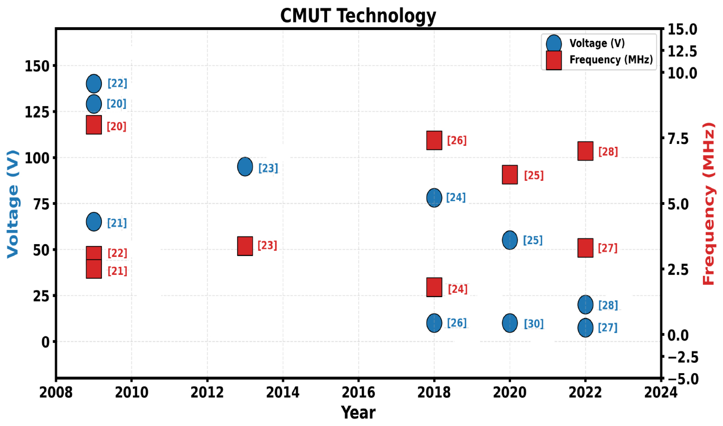
Figure 1 compares multiple CMUT research in terms of voltage and frequency, which we have already discussed in
Table 2. These parameters are critical in evaluating the suitability of each design for implementation in future CMUT-CMOS MEMS arrays. As we can see in
Figure 1, the voltage trend is getting lower, and the frequency is also higher.
2.2. Piezoelectric Transducers
Table 3 summarises various piezoelectric devices using materials like lead zirconate titanate (PZT), bismuth sodium titanate (BNT)-based ceramics, and polyvinylidene fluoride (PVDF) composites. Despite offering decent output voltages and energy harvesting potential, all listed devices lack compatibility with CMOS processes. Their fabrication methods are complex or material-specific, making them unsuitable for monolithic integration into MEMS.
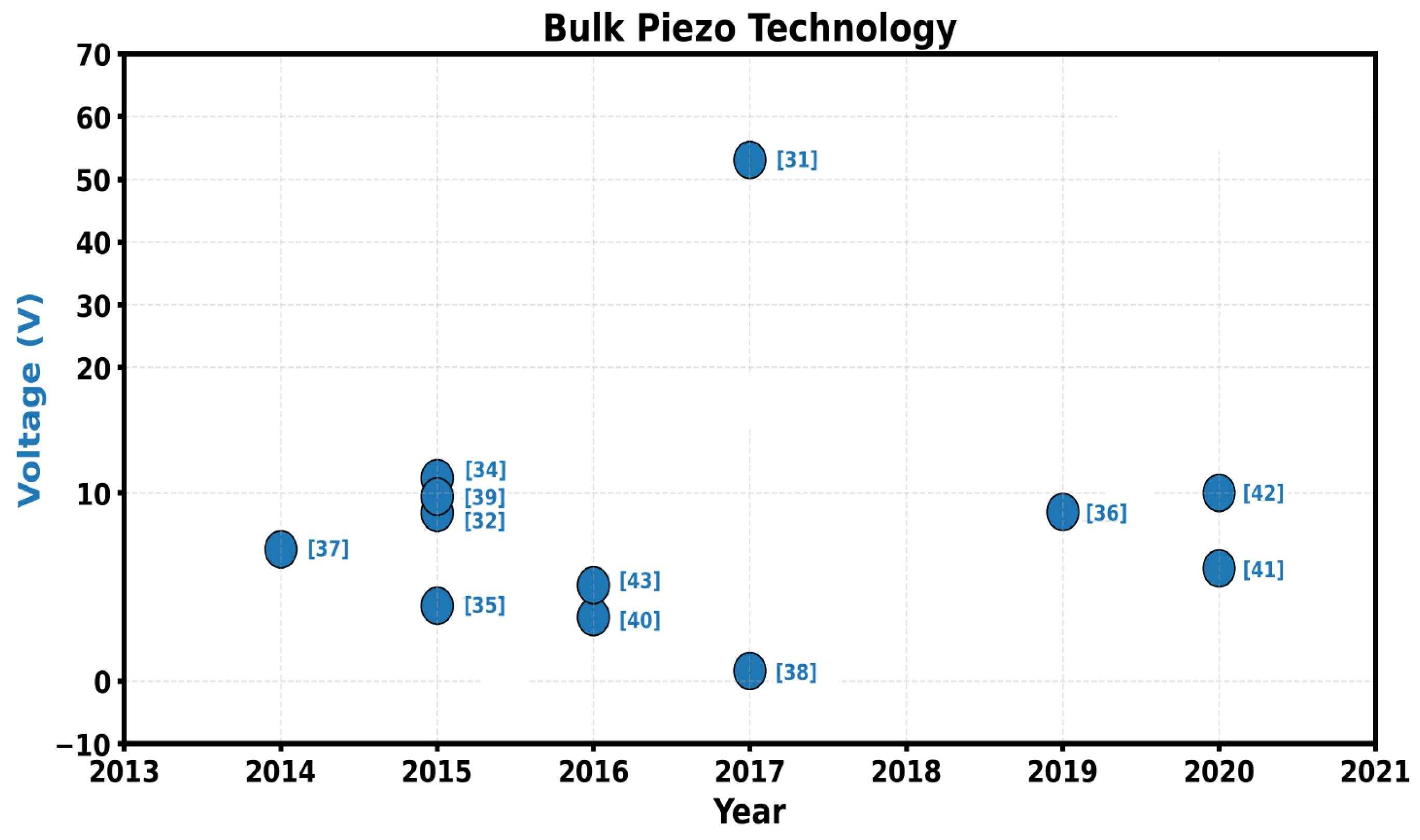
Additionally, many operate at low frequencies or are designed for wearable or energy-harvesting purposes, rather than high-frequency, high-resolution ultrasonic sensing. Hence, these bulk or polymer-based piezoelectric devices are not ideal for integration into CMOS–MEMS arrays in future automotive systems. Most cases we consider peak to peak volatge (Vpp). In the
Figure 2, we have seen different technologies in which we have compared the voltage across years. While the piezoelectric has required maximum voltage, and the compatibility with CMOS is quite low.
2.3. PMUT Transducers
Table 4 evaluates PMUT designs based on different piezoelectric materials. Most devices use PZT or AlN and operate in the low MHz range, often in water or air. While AlN-based PMUT show CMOS compatibility and low fabrication complexity, their bandwidth and resolution are moderate. PZT-based PMUT, though offering higher output and resolution, lack CMOS integration and are harder to fabricate at scale. Furthermore, the scalability of arrays remains limited, with only a few designs demonstrating high channel counts.
In contrast, CMUTs are inherently compatible with CMOS processes, enabling monolithic integration with driving electronics. They offer wider bandwidth, easier array scaling, and better resolution potential, especially in high-frequency applications. Thus, due to better CMOS integration, wide bandwidth, and higher array scalability, CMUT CMOS MEMS arrays are preferred over PMUT for next-generation ultrasonic applications. While PMUTs provide advantages in lower-frequency operations and flexible substrates, their integration with CMOS is more complex and less mature than CMUTs. Furthermore, the scalability of dense PMUT arrays remains challenging. Thus, this study focuses on CMUTs due to their higher integration potential and performance in our targeted application.
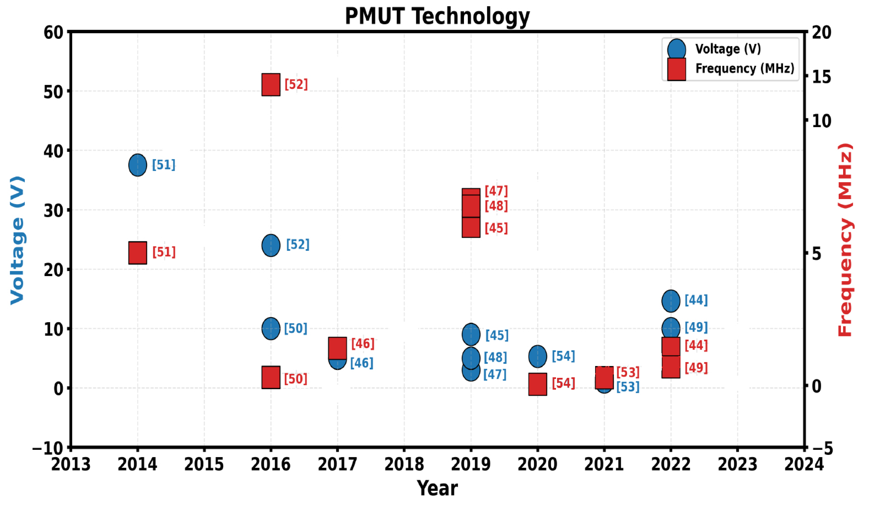
Figure 3 illustrates the comparative evaluation of PMUT technologies across two key metrics: voltage and frequency. While the comparison of the overall 6 important parameters is compiled in the
Table 2,
Table 3 and
Table 4. In the
Figure 3 we have used the voltage peak-to-peak (Vpp).
Based on the comprehensive evaluations provided in
Table 2,
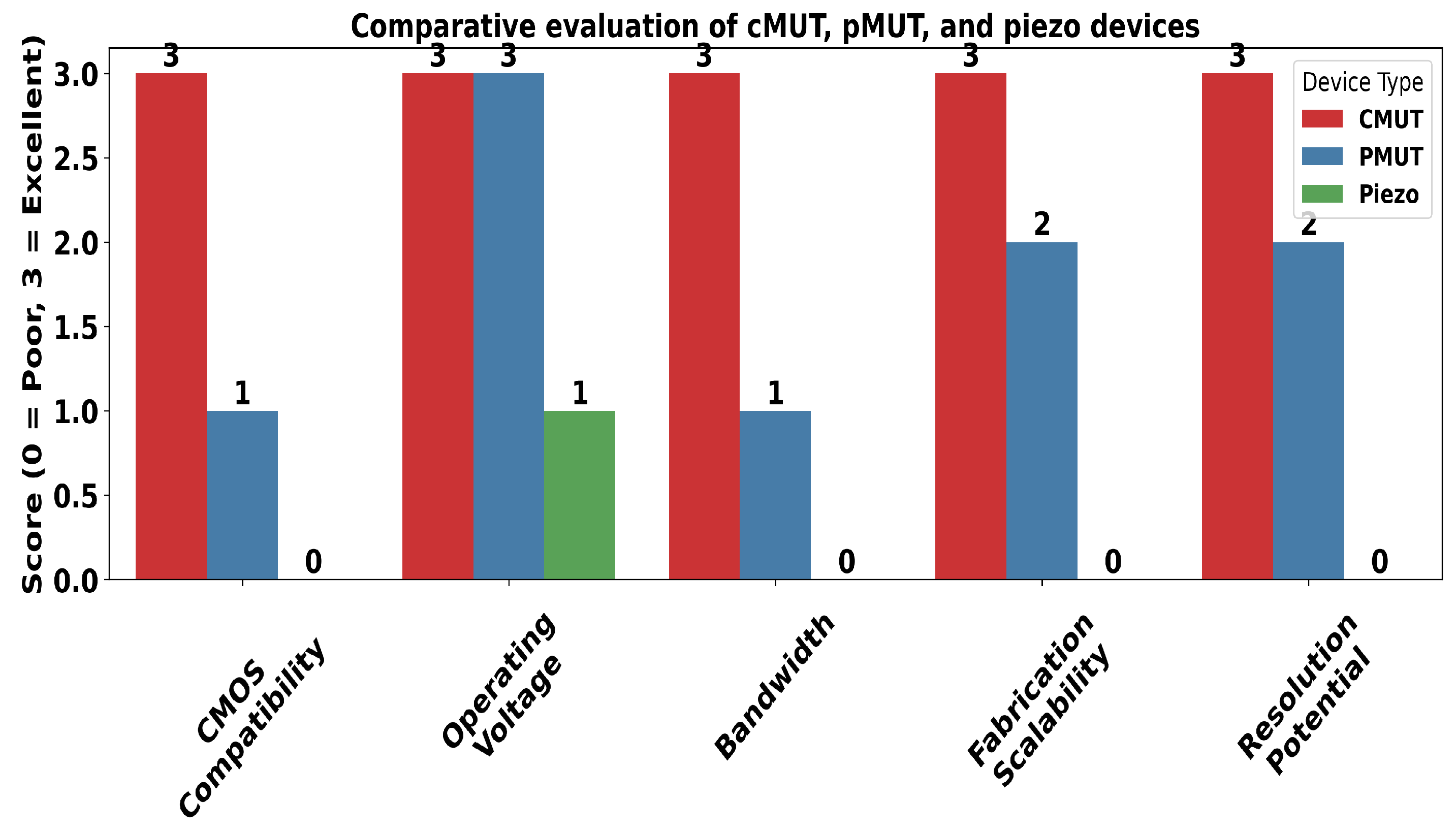
Table 3 and
Table 4, we propose that the CMUT–CMOS MEMS array is the most promising and scalable solution for next-generation vehicular sensing systems. CMUTs perform strongly across all key parameters, aligning with the future direction of automotive technologies—to replace bulky piezoelectric transducers with CMOS-integrated systems. The final comparison between CMUT, PMUT, and piezoelectric technologies, as shown in
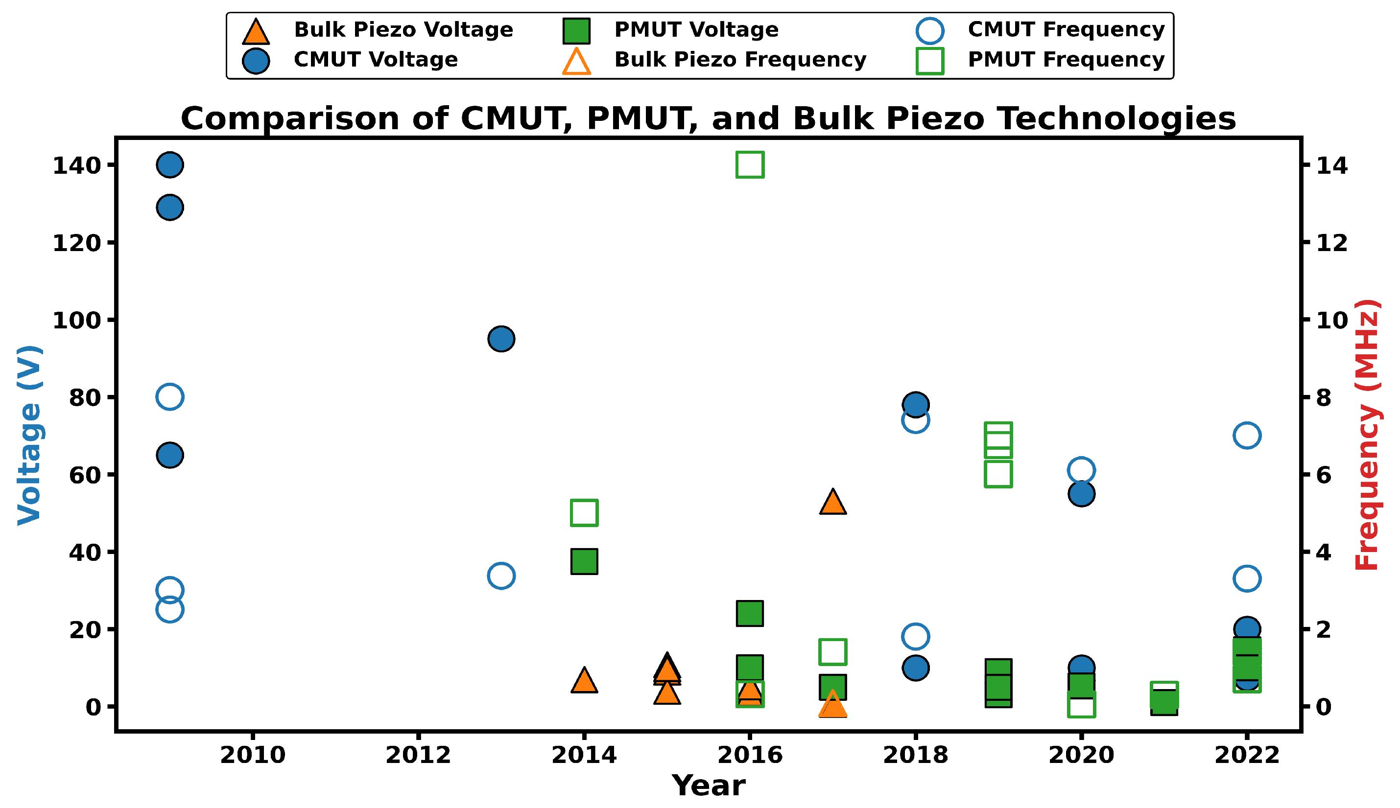
Figure 4, clearly indicates that CMUTs are better suited for CMOS integration and are more viable for future electric vehicle applications. CMUT–CMOS MEMS arrays offer full CMOS compatibility, enabling seamless monolithic integration with control electronics. They operate at moderate voltages—typically between 7.4 V and 25 V, with even lower thresholds achievable in some designs, making them energy-efficient and practical. Their broad bandwidths, reaching up to 150%, enhance both resolution and adaptability. Additionally, scalable fabrication methods such as wafer bonding and surface micromachining make them ideal for large-scale array deployments. Combined with high-resolution potential enabled by dense array configurations and tunable high-frequency operation, these attributes strongly support the view that CMUT–CMOS technologies are poised to outperform and eventually replace traditional piezoelectric and PMUT-based transducers in future automotive systems.
Figure 5 presents a comparative scoring of CMUT, PMUT, and piezoelectric devices across all critical performance factors for MEMS arrays. CMUT demonstrates consistently excellent performance with top scores in all categories, indicating strong suitability for integration and high-performance operation.
Figure 5 is based on
Table 2,
Table 3 and
Table 4. In the
Figure 5 scores were derived using normalized metrics (e.g., bandwidth, CMOS compatibility, operating voltage) from
Table 2,
Table 3 and
Table 4, each mapped to a 0–3 scale based on the reported best-in-class values across references.
2.4. CMUT and PMUT Transducers Analysis
CMUTs consist of a vibrating membrane suspended above a fixed electrode with a submicron vacuum gap. Electrostatic actuation via a DC+AC voltage combination drives membrane vibration, and returning acoustic waves modulate the gap capacitance, producing a current signal. CMOS-compatible CMUTs offer monolithic integration with electronics, making them ideal for applications such as parking assistance, blind-spot monitoring, and 360° ultrasonic imaging.
Recent studies [
6,
8,
56,
57,
58,
59,
60,
61,
62,
63,
64,
65,
66,
67,
68] demonstrate progress in CMUT and PMUT technologies—spanning gesture recognition [
6], distortion correction [
8], low-cost 3D ultrasound arrays [
64], and high-resolution CMOS integration [
65,
66,
67,
68]. The key limitations are in achieving large-scale, uniform MEMS arrays, which are essential for dense, high-performance sensing systems requiring precise control over membrane uniformity, interconnect complexity, and array scalability. Both CMUT and PMUT technologies face challenges in achieving large-scale uniform MEMS arrays, though CMUTs benefit from more mature CMOS-compatible processes. Different parameters we have are:
A = membrane area,
a = membrane radius,
Y = Young’s modulus,
D = aperture diameter,
R = radial distance to target,
= permittivity of free space,
f = frequency,
= time-varying gap,
= DC bias voltage,
= AC excitation voltage,
= total input voltage,
= electrostatic force,
= time-varying capacitance,
= induced current,
= membrane displacement,
= nominal gap,
= gap variation amplitude,
= acoustic pressure at distance
r and time
t,
D (PMUT) = electric displacement,
d = piezoelectric coefficient,
T = mechanical stress,
= permittivity,
E = electric field,
S = mechanical strain,
= nominal displacement,
= oscillation amplitude,
= resonant frequency,
t = diaphragm thickness,
= material density,
= Poisson’s ratio.
Table 5 summarises the core physical equations governing CMUT operation, linking capacitance, input voltage, electrostatic force, and acoustic pressure to dynamic membrane motion. It highlights how time-varying gaps and excitation signals influence sensing, actuation, and CMOS integration.
Table 6 summarises the core physical equations governing PMUT operation, linking piezoelectric displacement, mechanical strain, and excitation signals to diaphragm motion and acoustic pressure generation. It highlights how material properties and diaphragm structure influence actuation efficiency and ultrasound radiation.
PMUTs utilise a diaphragm-integrated piezoelectric layer to convert electrical energy into mechanical vibration and vice versa, based on the direct and inverse piezoelectric effects. Applying an AC voltage induces strain, causing the diaphragm to oscillate; incoming pressure waves then deform the diaphragm and generate an output voltage. These recent studies [
6,
7,
13,
69] highlight the versatility and expanding functionality of PMUTs across sensing, interaction, and acoustic applications. But key limitations are in achieving large-scale, uniform MEMS arrays.
3. Governing Equations and Framework for CMUT-CMOS-Based Automotive Ultrasound Beamformer
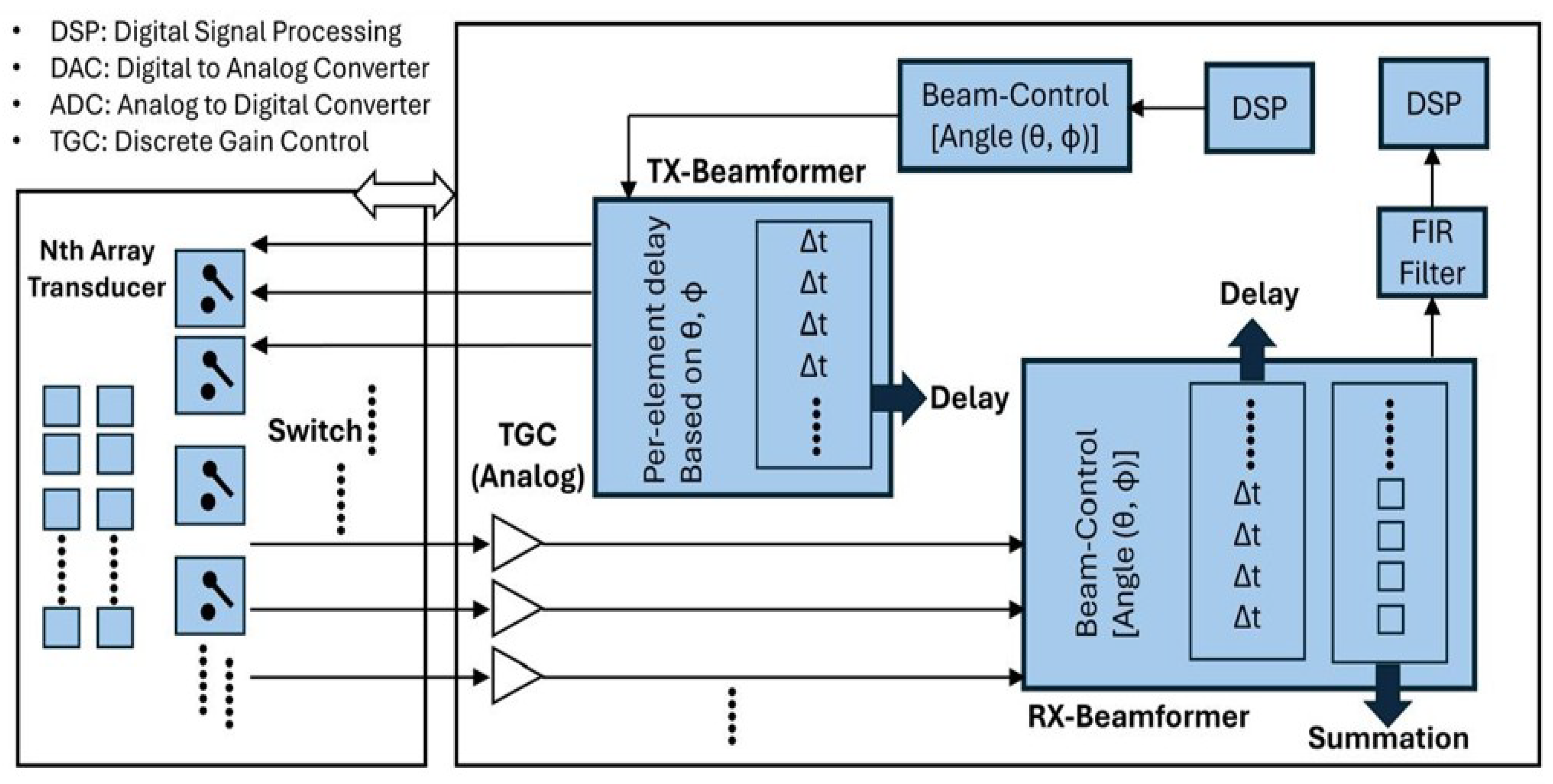
This section outlines the core equations governing a CMUT-CMOS-based ultrasound beamformer designed for top-mounted integration on vehicles. The system provides 360° directional coverage and an extended range, thereby enhancing autonomous navigation and object detection. We propose replacing conventional bulky piezoelectric transducers with compact CMUT-CMOS MEMS arrays. This shift enables dense integration, reduced size, and improved resolution. The design employs a 3D beamforming approach for efficient and accurate spatial sensing. The array structure for beamformer design can be seen in
Figure 6.
Figure 7 shows a full-coverage CMUT beamformer where the same array handles both transmission and reception using switch-controlled and delay units. TX and RX paths apply angle-based delays and beam control for 3D directional scanning, with digital signal processing (DSP) handling post-processing. Here, full coverage refers to angular beam steering across 360° in azimuth and ±90° elevation, achieved by dynamic phase delays in the array. The switch shown toggles CMUT elements between transmit and receive states using CMOS control logic. TX and RX beam paths are digitally timed and phase-adjusted independently.
Table 7 outlines essential equations governing CMUT-based beamforming and signal processing, covering delay control, signal shaping, resolution, and correlation. These formulations are fundamental to achieving real-time, high-resolution 3D sensing in autonomous systems.
4. Discussion and Futuristic Scope
Recent advances in automotive sensing are enabling safer and more efficient autonomous systems. LiDAR-based systems improve adaptive cruise control and steering in complex environments [
70], while broadband bidirectional beamformers enhance bidirectional signal processing for both transmission and reception [
71]. Meanwhile, the emergence of 6G introduces unified 3D network architectures—integrating space, air, and ground connectivity—that redefine the sensing and communication landscape [
72]. Simultaneously, multimodal task frameworks help manage latency by categorising data processing based on complexity and tolerance [
73].
Our estimated signal current of
, derived from
and a capacitance modulation rate of
, is well within the detectable range of CMOS readout circuits, aligning with performance in prior CMOS-based voltage sensing systems that achieve
[
74,
75]. The estimated acoustic pressure and time-of-flight delays derived from
Section 3 also align with short-range mmWave radar and ultrasonic systems, supporting centimetre-level resolution under optimal conditions. Compared to LED-based indirect voltage sensing (with error
) [
76], the proposed CMUT system remains competitive in monitoring voltage changes via electromechanical transduction rather than optical means. Although LED systems achieve superior isolation, CMUTs offer higher integration with silicon-based electronics.
Spintronic STNO-based FDM architectures [
77] and AiP beamformers operating at 57–66
[
78] demonstrate compact, low-power, high-data-rate performance for automotive scenarios. However, our CMUT-CMOS solution provides a unique balance of spatial resolution, real-time reconfigurability, and integration potential. Unlike mmWave AiP modules, which typically require external RF components and calibration, our beamformer enables programmable delay logic within a fully electronic MEMS-CMOS stack, supporting real-time 3D sensing with lower power consumption. The proposed CMUT-CMOS ultrasonic beamformer thus offers a compact, fully electronic alternative to mechanical transducers—enabling real-time 3D sensing with centimetre-scale resolution. By tuning membrane gap, aperture diameter, and operating frequency (as shown in
Section 3), we demonstrate that key acoustic and electrical metrics are directly scalable to match application-specific constraints. Future integrations may include scalable
or
sensor arrays with edge-local processing, AI-powered adaptive beam control for object classification, and automated fabrication workflows. While this architecture is ideal for advanced driver-assistance systems (ADAS), its utility extends to robotic mapping, medical imaging, and smart home sensing, positioning the CMUT-CMOS platform as a robust candidate for next-generation ISAC systems.
