1. Introduction
The Biefeld–Brown effect is based on generating gaseous ions that move from an electrode—the emitter—towards a collector with an opposite electric charge. As the ions move between those two electrodes, their momentum is transferred, and a thrust is produced. Electrohydrodynamic (EHD) propellers provide a certain advantage in that they do not contain any moving parts. Compared to conventional propellers, their structure is simple, comprising only two electrodes mounted on an insulator support, which maintains the distance between them. As for the noise level, they are much more silent than conventional alternatives.
From a physical point of view, the Biefeld–Brown effect is an electrohydrodynamic process in which the produced ions transfer their momentum to air molecules. When subjected to a high voltage, this effect produces a force acting on an asymmetric capacitor [
1,
2]. When the voltage magnitude is sufficient for triggering a corona discharge, the ions move faster from the corona electrode to the collector, which has a surface with a larger radius of curvature. In this process, the ions transfer their momentum to neutral air molecules, which leave the electrode system outside. Due to the asymmetrical distribution of the electric field, the direction of that movement is preserved regardless of the polarity. The opposite force exerted on the whole system is based on the law of the conservation of momentum [
3,
4].
The value of the voltage between the electrodes depends on the particular application, and it may amount to values ranging from kilovolts to megavolts. The most efficient inter-electrode distance is determined so that the electric field reaches a value just below the breakdown voltage of the air, which produces the so-called corona saturation current [
5].
In the area near the discharge electrode of a small radius of curvature, an intensive gradient of the electric potential field is formed, causing the ionisation of the air. This is accompanied by the formation of mostly ions, with a charge determined by the polarity of the electrode. The maximum potential speed of the movement of those ions directly depends on their mobility in a gaseous environment. Humidity has a negative effect, as it significantly reduces the ions’ mobility as well as the breakdown voltage [
4,
6]. In contrast, as the temperature increases, the mobility also increases. Water, as a polar molecule, may form conductive bridges between the electrodes that lead to an undesired breakdown [
7,
8]. This can occur only if the electrodes are sufficiently close to each other, or if water condenses onto the insulator support.
The Biefeld–Brown effect is present in both the positive and the negative polarities; however, it has been observed that the power is slightly higher in the case of a positively charged emitting electrode. This is affected by various ionising energies and electron affinities of the molecules in the air. Another decisive fact is that nitrogen cations (N
2+) exhibit a higher mobility than oxygen anions (O
2−). Furthermore, the mechanisms of the positive and the negative coronas differ [
9,
10].
As the ambient pressure decreases, the density of molecules in the environment around the electrode also decreases, which leads to a lower number of ionised particles and a lower probability of collisions between those particles and neutral molecules. As a result, the thrust intensity decreases, and so does the breakdown voltage. Consequently, the intensity of the electrostatic forces also decreases [
3].
At very low pressures, positive results were only observed when an extremely high voltage was applied, as it increased the probability of ionisation in an environment with a minimum number of residual molecules. Those ions were subsequently attracted by an electrode with an opposite charge, near which they were neutralised [
3,
11].
At pressures below 1 Pa, in systems using a very high voltage, the formation of cathode radiation with ionising effects may occur [
12]. In an ideal vacuum, where no particles capable of carrying a charge are present, the formation of a propelling force is impossible [
10].
However, from the point of view of the quantum field theory, a vacuum is not empty; instead, it is an environment capable of polarisation and magnetisation. It contains so-called virtual particle–antiparticle pairs with a very short lifetime—vacuum bubbles. Such pairs are, for example, electron–positron pairs, which behave like electric dipoles in an electric field. Due to the effects of the field, these pairs move, causing the polarisation of the vacuum.
In the initial stage of the development of EHD technology, the thrust produced was so low that the generated kinetic energy was negligible compared to the weight of the whole system [
10]. Therefore, propelling units that used a flow of ionised particles were only applied in research missions conducted in space, where even a low acceleration may bring about a desired effect if applied for a prolonged period of time.
On Earth, the same principle has been increasingly applied. At present, EHD propulsion is used, for example, in specific types of pumps, as well as in the production of high-precision printing and in food drying technologies. In microbiology, the use of electroosmosis is dynamically developing for the purpose of water extraction from salt solutions. In combination with electrophoresis, which facilitates the separation of individual ions, these technologies offer a wide range of applications, primarily in the field of genetic engineering [
13].
In recent years, EHD propulsion has also been intensively developed for use in unmanned aerial vehicles (UAVs). Compared to conventional propulsion units, EHD-propelled vehicles exhibit significantly lower noise levels, which makes them an attractive technology for the defence industry [
14,
15].
Key examples include the Silent Ventus UAV, developed by Undefined Technologies in 2023. The latest version comprises two electrodes with a potential gradient of 40 kV maintained between them. They are powered by a lithium-ion battery. The equipment is capable of flying for more than 4 min. Compared to conventional UAVs, its noise level is significantly lower, reaching levels as low as 70 dB [
16].
Another innovative piece of equipment is the MIT EAD Airframe V2, an aircraft developed by a research team at the Massachusetts Institute of Technology. The experimental model is 2 m long; its wingspan is 5.14 m, and its total weight is 2.45 kg. It is powered by lithium-ion accumulators installed in the front part of the airframe. Electrodes with opposite polarities are connected to a two-stage Cockcroft–Walton multiplier. The inter-electrode distance is 50 mm, while the voltage generated between them amounts to 40.3 kV. As a result, the system generates a maximum thrust of 3.2 N and reaches a speed of 4.8 m/s. However, due to the limited capacity of the battery, the aircraft is only capable of flying for approximately 90 s [
17].
One of the key advantages of EHD-propelled engines, when compared to conventional propulsion, is their ability to generate a thrust that is of lower values but lasts for a longer period of time. That facilitates, for example, cosmic probes that are capable of reaching higher speeds over a long-term time horizon. A decisive factor is the impulse of the force, i.e., the product of the force magnitude and the time for which it is exerted—which is much higher in the case of EHD propulsion compared to conventional engines.
Thanks to the progress taking place in the development of novel materials, ultralight alloys, more efficient accumulator systems and control electronics, it has been possible to significantly reduce the total weight of propeller units. As a result, EHD technology is now capable of producing kinetic energy that is sufficient for the movement of equipment in applications on Earth.
In this article, the effect of the effective length and diameter of electrodes on the propulsion parameters of EHD propellers is investigated. The benefit of the article consists in providing a detailed analysis and evaluation of the findings observed in experiments, with the aim of proving the potential application of EHD propellers in terrestrial conditions. The novel contribution of this work lies mainly in testing unique electrode pairs that enable a broad-spectrum recombinability and interchangeability. The tested combinations offer a wider range of possibilities for testing electrohydrodynamic processes, depending on the parameters of the electrode pairs.
2. Process of Gas Ionisation and Genesis of the Corona Discharge
A corona discharge is typically produced at voltages lower than the breakdown voltage of a material (air). This effect is primarily observed at ambient pressures over 1000 Pa, and its occurrence is closely related to the geometry of the electrodes, in particular, a small radius of their curvature, which causes an uneven distribution of the electric field [
18].
In order to trigger a corona discharge, the intensity of the electric field around the emitting electrode must be higher than a certain critical value. This value may be approximately identified using a number of empirical equations, the best known of them being Peek’s law, which is often adjusted to the current conditions:
where
mₐ is the coefficient depending on the quality of the electrode surface (1);
δ is the correction factor related to the ambient pressure and temperature (1); and
DE is the diameter of the emitter (cm) [
19].
Due to the variability of the effects of the surrounding environment, the critical voltage is often identified experimentally.
The behaviour of a corona discharge depends not only on the geometry of the electrodes, but also on the type of gas, as well as the applied voltage and its polarity [
20]. A corona may be positive or negative [
21]. One feature that is common to all corona discharges is that a corona discharge is a non-thermodynamic system, i.e., non-thermal plasma [
22].
Although the resulting thrust is not directly affected by the polarity, with a positive electrode, the propulsive efficiency is slightly higher. The direction of the acting force is the same in the case of both polarities [
23]. With a positive corona, nitrogen ions are dominant, while a negative corona is formed in electro-negative gases, where mostly oxygen anions are generated. Subsequently, those ions collide with neutral air molecules, which results in the formation of secondary ions of positive as well as negative charges [
19].
The resulting electrohydrodynamic force may then be calculated using Equation (2) [
4]:
where
d is the inter-electrode distance (m),
I is the electric current (A) and
μm is the ion mobility (A∙s
2∙kg
−1).
Townsend’s empirical relation describes a nonlinear correlation between the current and the intensity of the electric field in a dielectric environment, taking into consideration the ionisation processes running in the gaps between the electrodes. It is described by Equation (3):
where C is the constant depending on the shape of the electrodes (A∙V
−1),
U is the voltage at electric current
I (V) and
U0 is the voltage at which a corona is produced (V).
Typically, a negative corona is distributed unevenly—it mostly occurs on the sharp edges of the electrode. Compared to a positive corona, it has a slightly higher volume and a higher density of free electrons. However, those electrons have a lower energy. A negative discharge is formed as a result of electron avalanches that propagate from the negative electrode to the positive electrode. At a certain distance from the emitter, the electric field intensity decreases, so the electrons lose their energy and collide with neutral molecules, thus generating more carriers of the negative charge. In the atmosphere, a negative corona is manifested as purplish mist [
24].
The positive corona that was used in the experiments exhibited a homogeneous distribution and produced blue-white radiation, with the emission spectrum mostly in the ultraviolet region. Its regular nature was caused by the formation of secondary electron avalanches. With identical configurations of the electrodes, its range was lower than that of the corresponding negative corona [
25,
26].
An advantage of the positive corona is the lower production of ozone, which contributes to the experiment’s safety, since ozone has irritating and corrosive effects [
27,
28].
An assessment of the propulsion parameters requires an identification of the air parameters. The parameter that must be identified for the purpose of calculating the induced force and the propulsion performance is the air density. The resulting density of the atmospheric air is therefore a complex function of the physical conditions in the environment, and it changes with different geographic locations and the altitude above sea level, as well as the current meteorological conditions.
By applying Avogadro’s law—stating that equal volumes of ideal gases, at an identical pressure and temperature, contain an equal number of molecules—it is possible to derive an equation for calculating the molar mass of humid air. Equation (4) is expressed as follows:
where
xda is the mole fraction of dry air (1),
Mda is the molar mass of dry air (28.966 kg·kmol
−1),
xms is the mole fraction of water vapour (1) and
Mms is the molar mass of water vapour (18.016 kg·kmol
−1).
The mole fraction of water vapour, which represents the ratio of the amount of the substance of water vapour to the total amount of gas in the mixture, is identified by applying the ratio of the partial pressure of water vapour to the total pressure of the gaseous mixture. Equation (5) is based on Dalton’s law of partial pressures, and it is used to calculate the physical properties of humid air.
where
RH is the relative humidity (1),
p is the atmospheric pressure (Pa) and
psat is the pressure of saturated vapour (Pa).
The pressure of saturated water vapour at positive temperatures is often calculated using Tetens’ empirical formula, which provides a good approximation of the correlation between the saturated vapour pressure and the temperature in normal atmospheric conditions. It is mathematically expressed as follows (6):
where
t is the air temperature (°C).
The real power is then calculated using the following Equation (7):
where
is the real force produced by the ionic wind (N),
is the real speed of the ionic wind (m·s
−1),
is the air density (kg·m
−3) and
S is the cross-sectional area of the flow (m
2).
The propulsion efficiency is identified as the ratio of the real power to the output electric power of the asymmetrical capacitor with a DC voltage supplied to its terminals, as follows (8):
where
Pel is the electric power input (W).
3. Experimental Apparatus
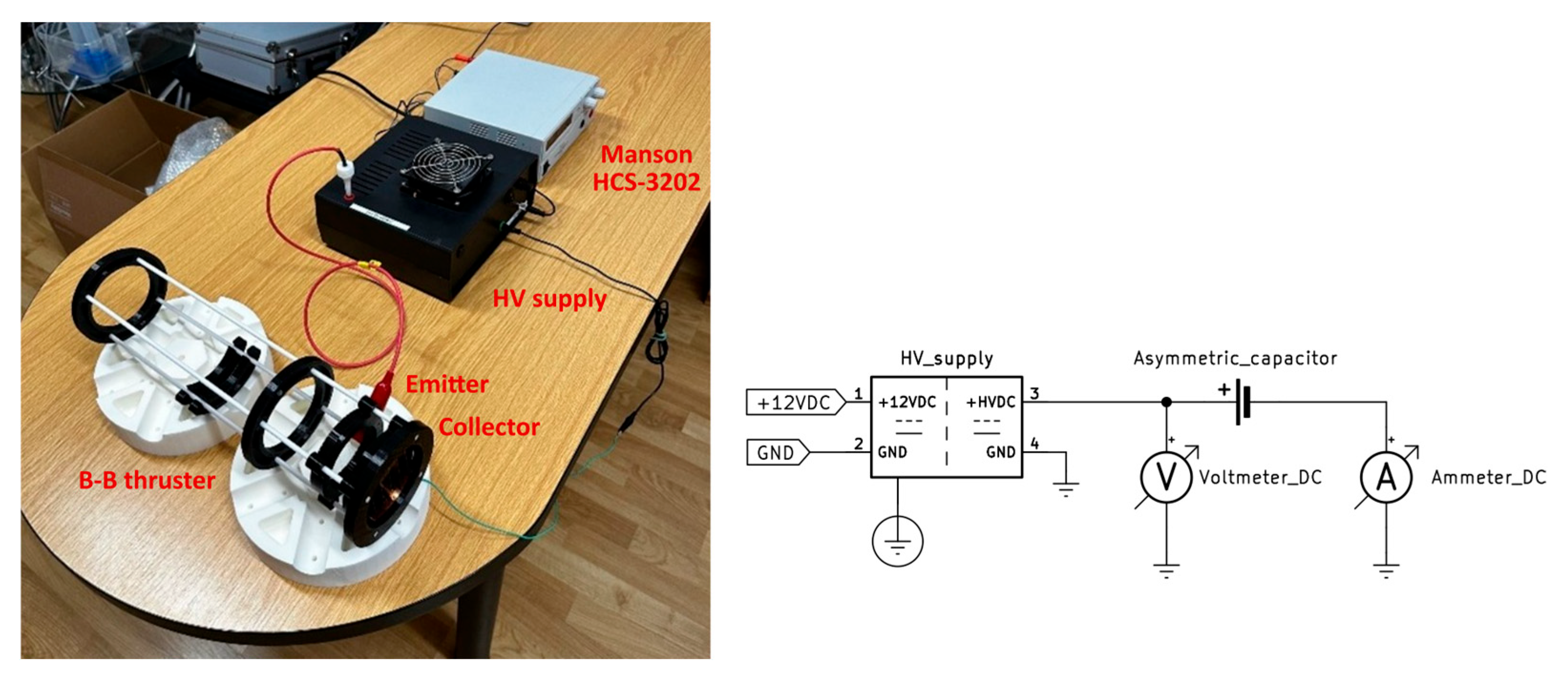
The testing of functionalities of various designs of propulsion systems and the individual design modifications was carried out while gradually increasing the inter-electrode distance
L by using an EHD propulsion apparatus (
Figure 1). This process was coordinated while increasing the potential gradient between the electrodes up to the breakdown voltage.
The high-voltage source had a flyback topology. The adjustable high-voltage source with an output voltage of up to +40 kV and integrated current regulation represents a compact and reliable solution for professional and laboratory applications that require a stable source of a high DC voltage. The device converts a low DC voltage (12 VDC) into an output voltage with a positive polarity ranging from 0 to 40 kV.
The level of the output voltage was smoothly adjustable using an external potentiometer with a resistance of 10 kΩ, which facilitated a precise adjustment of the required value to the existing application requirements.
The source concept was focused on safety and stability. The EHD propulsion apparatus also included an output current limiter with a fixed adjustment, which limited the short-circuit current to a maximum of 10 mA. This feature significantly increases the safety of a device, especially in the case of an unintentional short-circuit or when working with experimental apparatuses with variable impedances. The apparatus also included a high-voltage resistor of 10 MΩ, with a maximum working voltage of 100 kV and a power of 10 W. The technical design of the device comprised an input power source with a range of 10–12.5 VDC, with a maximum current withdrawal of up to 2 A. The device was placed in an ABS cabinet of compact dimensions. The forced convection cooling of the power elements was provided using a fan. The source also included protection against the input voltage polarity’s reversal.
The voltage on the terminals of the asymmetrical capacitor was measured using an HVP-40 probe with an accuracy of ±5% (1–20 kV DC) and ±6% (20–40 kV DC) and a UNI-T UT89X multimetre with a precision of ±0.5% + 2 digit at a 60.00 VDC range. The same probe was used for all measurements, so the relative deviation does not affect the comparisons between experiments. The magnitude of the electric current flowing between the electrodes was measured using a GOSSEN METRAWATT METRAHIT 2A precision analogue multimetre (±2.5% of the measured value), thanks to which only a low decrease in the voltage occurred through the measuring resistor. The output speed of the accelerated medium was measured using an FVAD 15-HMK5 precision vane anemometer with an accuracy of ± (+0.5% of the final value sensor + 1.0% of the measured value).
The laboratory environmental conditions, in particular the atmospheric pressure, relative air humidity and temperature, were measured and regulated using a COMET D4130 device (±0.4 °C; ±2.5%RH in the interval 5 to 95%RH at 23 °C; ±2 hPa at 23 °C) (
Table 1).
The newly designed device for accelerating the surrounding medium consisted of a modular system comprising anode–cathode electrode pairs that facilitated variable adjustments of the inter-electrode distance. With regard to the operational requirements, it was necessary to ensure a continuous supply of the surrounding air into the inter-stage gaps between the electrodes.
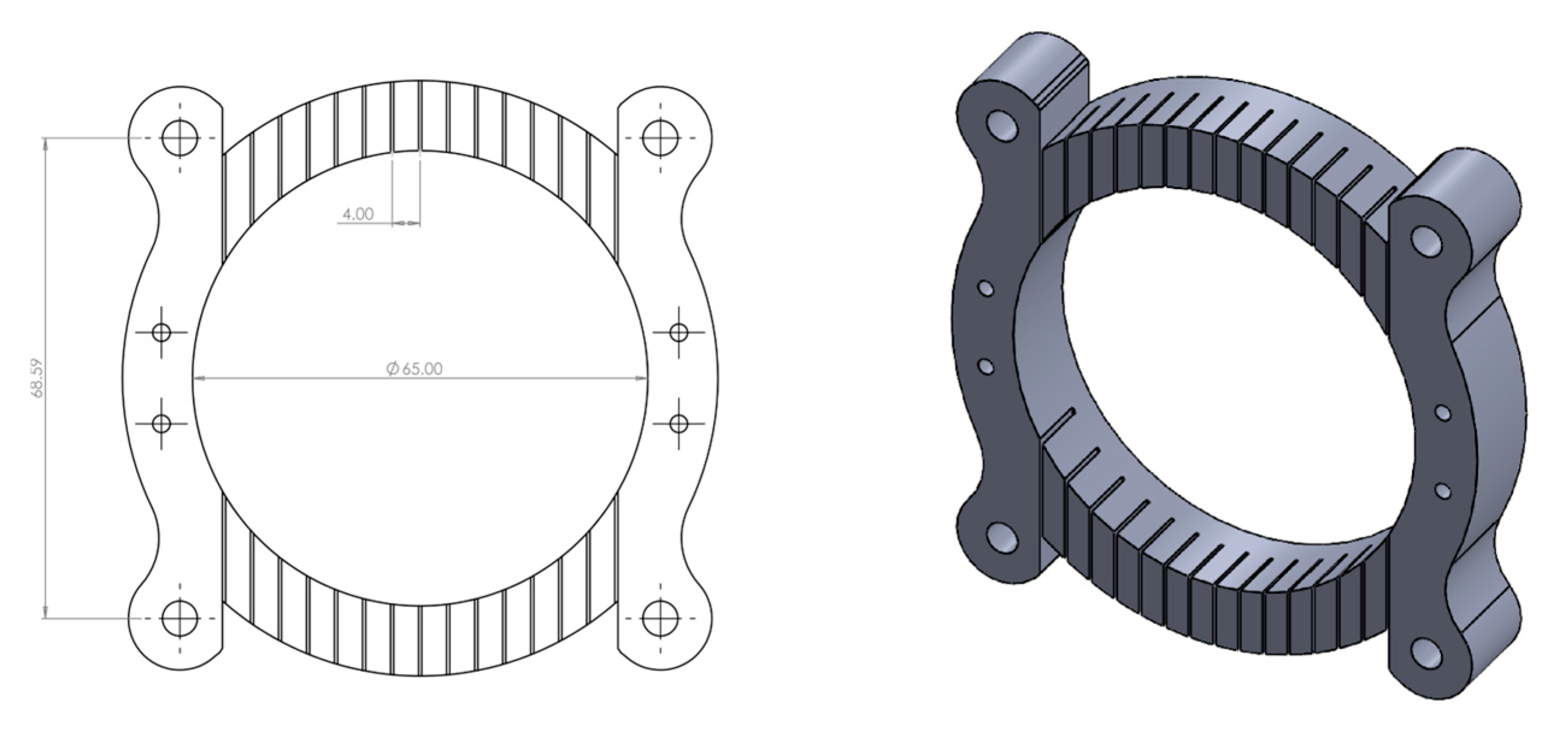
Therefore, the design was created with an open structure, consisting of an arrangement with a single stage of movement freedom. This was possible thanks to four parallel linear conductors made of laminated logs. Their mutual positions were secured not only by the electrodes, but also by PETG rings. The electrodes, i.e., the emitter and the collector, had a comb-like structure that facilitated the installation of conductors and determined their spacing. They were all made of PETG by applying 3D printing technology. Their arrangement with a slight overlap prevented their spontaneous movement. The cross-sectional areas of the flow of all of the electrode pairs were identical—0.003217 m2. In a frontal contact, the inter-electrode distance was 10 mm.
The emitters were constructed in four designs with the same structure, but with different diameters of the coronating conductor and effective lengths of the conductor. The design with the conductor of the corona electrode with a diameter of 0.08 mm and an effective length of the electrode of 0.810 m was designated as (0.08)E0, while the one with an effective length of 0.392 m was designated as (0.08)E1, and the design with an effective length of 0.273 m was designated as (0.08)E2. The design with a coronating conductor of the emitter with a diameter of 0.15 mm and an effective length of 0.273 m was designated as (0.15)E2 (
Figure 2). The ends of the coronating conductors were fixed with nylon bolts with a metric thread. For better visibility purposes, the figure only shows the (0.15)E2 emitter.
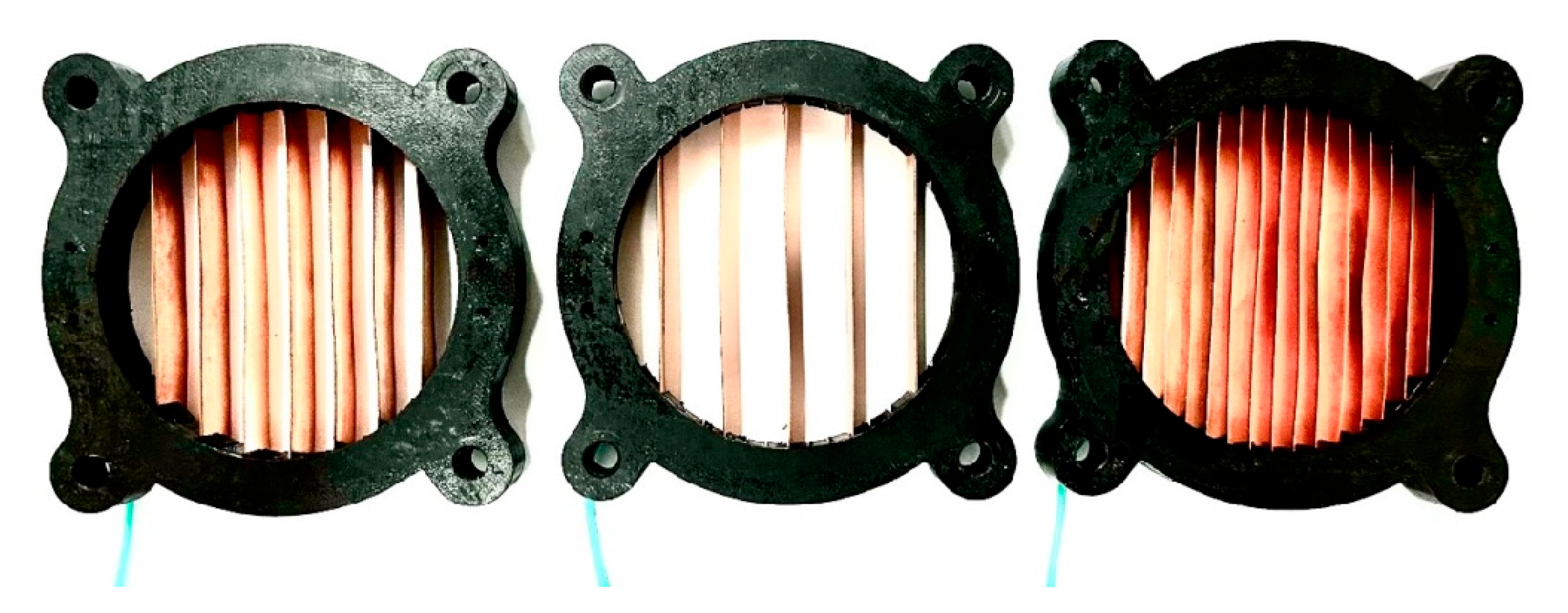
Similarly, the collectors were constructed in three identical designs, but with different effective lengths of the collector electrode. The conductors for the collectors were made of copper earthing bands, with a thickness of 0.5 mm and a width of 10 mm. On the back side of the collector, they were conductively joined in a bus made of the same copper band. The type of the collector conductor was the same in all of the collectors. The design with an effective length of the collector of 0.810 m was designated as K0, the one with an effective length of 0.392 m was designated as K1 and the design with an effective length of 0.273 m was designated as K2. The designs of the collectors are shown in
Figure 3.
4. Measurement and Testing Process
The purpose of the first experiment was to examine the effects of the diameter of the conductor of the corona electrode on the propulsion parameters. The first test was carried out with the configuration consisting of the (0.08)E0 emitter and K2 collector, arranged in a single stage. The shortest possible inter-electrode distance was only limited by the designs of their frames. The values that were measured and calculated in the experiment are listed in
Table 2.
The next test was carried out with the configuration consisting of the (0.15)E0 emitter and the K2 collector, arranged in a single stage. The shortest possible inter-electrode distance was only limited by the designs of their frames. In the case of the inter-electrode distance of 50 mm, the output speed of the accelerated medium was not recorded, since the value did not reach the threshold value. The values that were measured and calculated in the experiment are listed in
Table 3.
The purpose of the second experiment was to examine the effects of the effective lengths of the electrodes on the propulsion parameters. The first test was carried out with the configuration consisting of the (0.08)E0 emitter and the K0 collector, arranged in a single stage. The shortest possible inter-electrode distance was only limited by the designs of their frames. The values that were measured and calculated in the experiment are listed in
Table 4.
The next test was carried out with the configuration consisting of the (0.08)E1 emitter and the K1 collector, arranged in a single stage. No flashover was observed with this configuration, and the minimum inter-electrode distance was only limited by the design. In the case of the inter-electrode distance of 50 mm, the output speed of the accelerated medium was not recorded, since the values on the anemometer did not reach the threshold value. The values that were measured and calculated in the experiment are listed in
Table 5.
The last test was carried out with the configuration comprising the (0.08)E2 emitter and the K2 collector. The measurement was carried out from the basic inter-electrode distance. In the case of the inter-electrode distance of 50 mm, the output speed of the accelerated medium was not recorded, since the value did not reach the threshold value. The values that were measured and calculated in the experiment are listed in
Table 6.
5. Discussion
The purpose of the first series of experiments was to examine the effects of the diameter of the conductor of the corona electrode on critical propulsion parameters. As the conductor diameter increased, the curvature of the emitter’s surface decreased, resulting in a reduction in the local intensity of the electric field in its immediate vicinity. Consequently, the above-mentioned Peek’s law indicated a shift in the critical voltage required for triggering a corona discharge towards higher values.
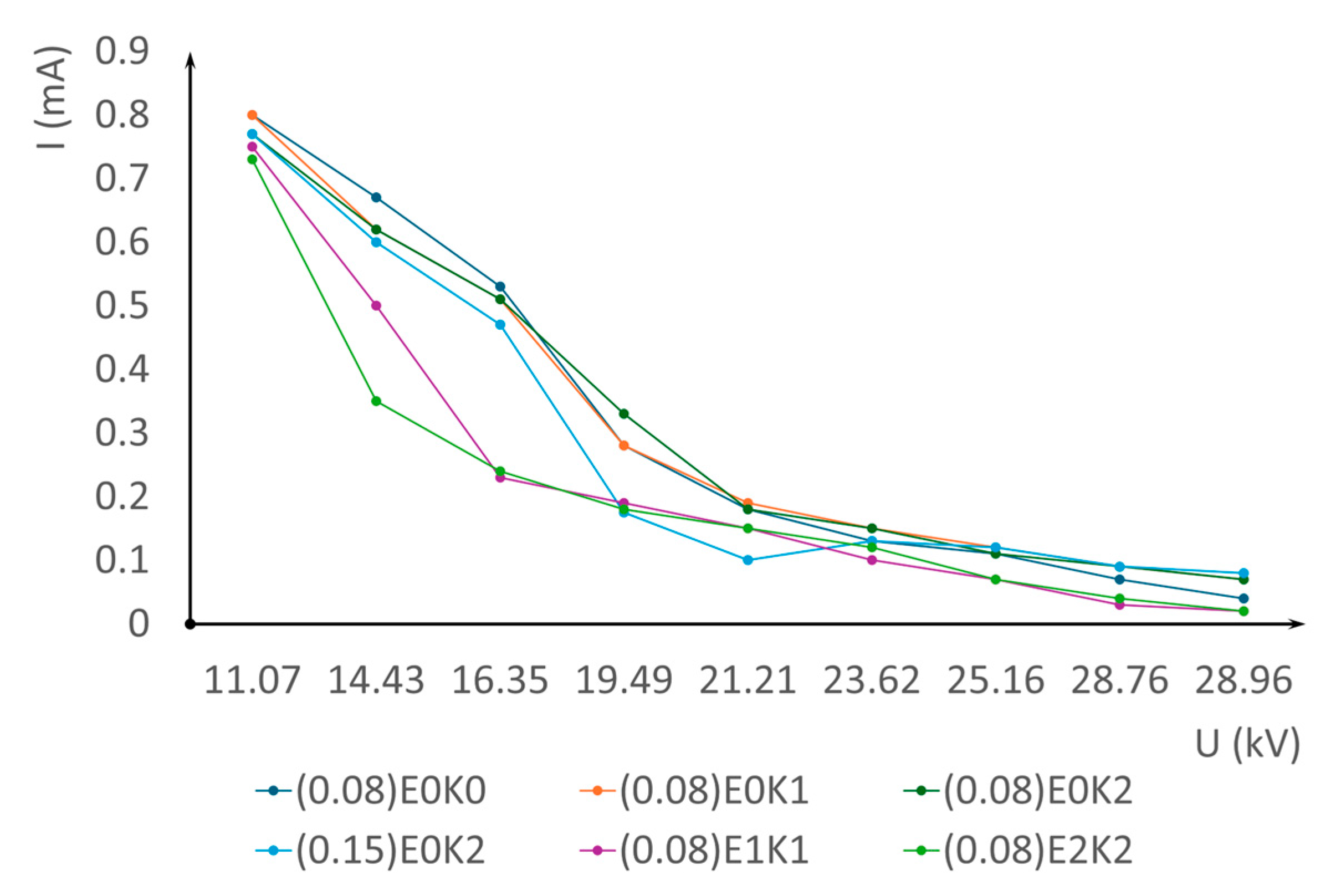
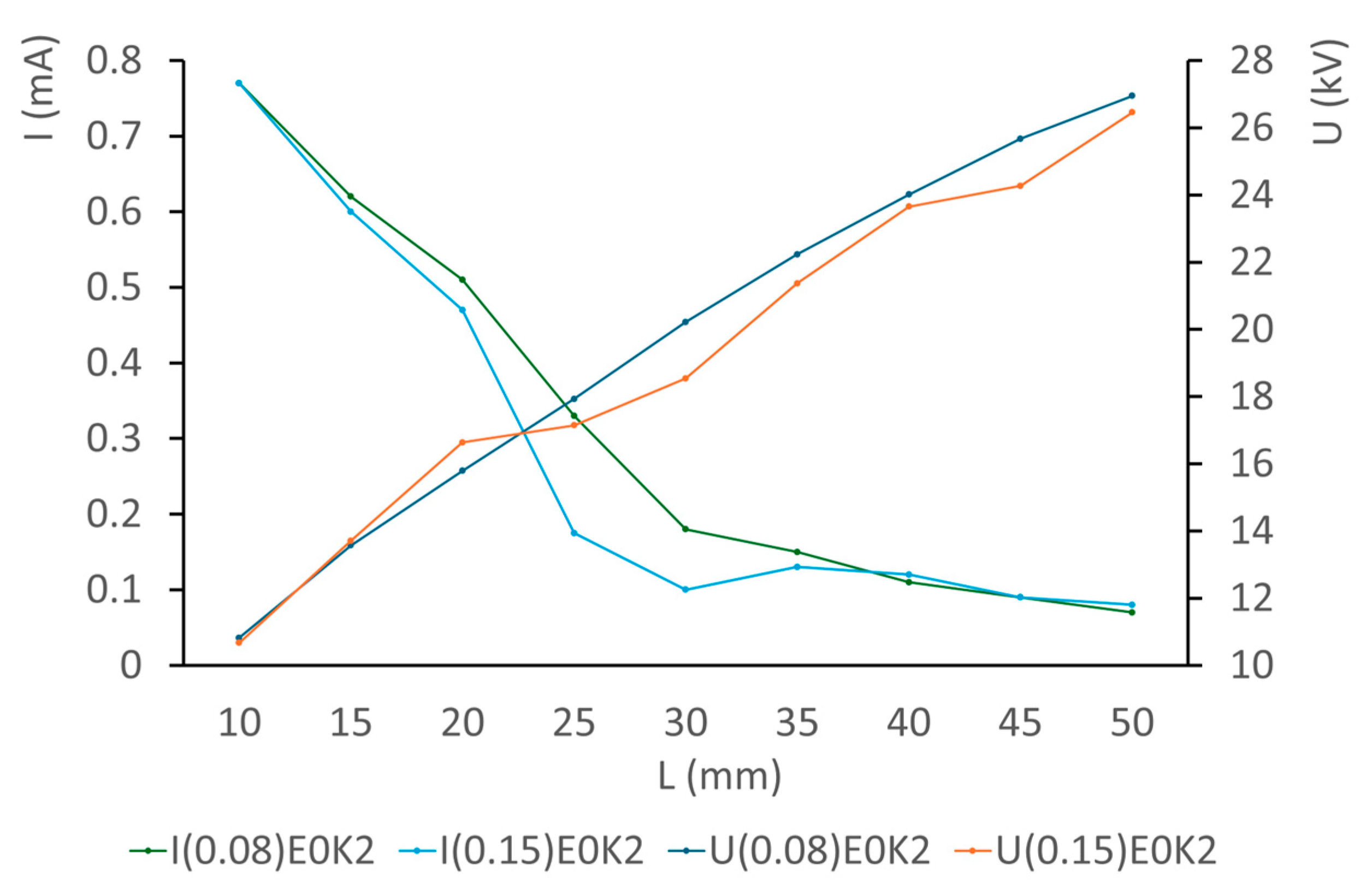
As a result, the ionisation phase duration was longer, and the efficiency of the formation of free charge carriers decreased. This phenomenon was also confirmed by an analysis of the voltage and current characteristics of the system for all inter-electrode distances (
Figure 4).
As for the distribution of the corona discharge, significant visual differences were also observed. With a thinner conductor with a diameter of 0.08 mm, the discharge looked more homogeneous, with a denser distribution and higher intensity of ionisation along the entire length of the electrode. On the other hand, with the conductor having a larger diameter of 0.15 mm, the discharge behaviour was less homogeneous, while the discharge was primarily concentrated in the zones with local irregularities in the curvature (comb edges), indicating a less homogeneous distribution of the current density across the entire cross-sectional area. The average value of the electric current flowing between the electrodes was notably higher in the (0.08)E0K2 system than in the (0.15)E0K2 system (
Figure 5).
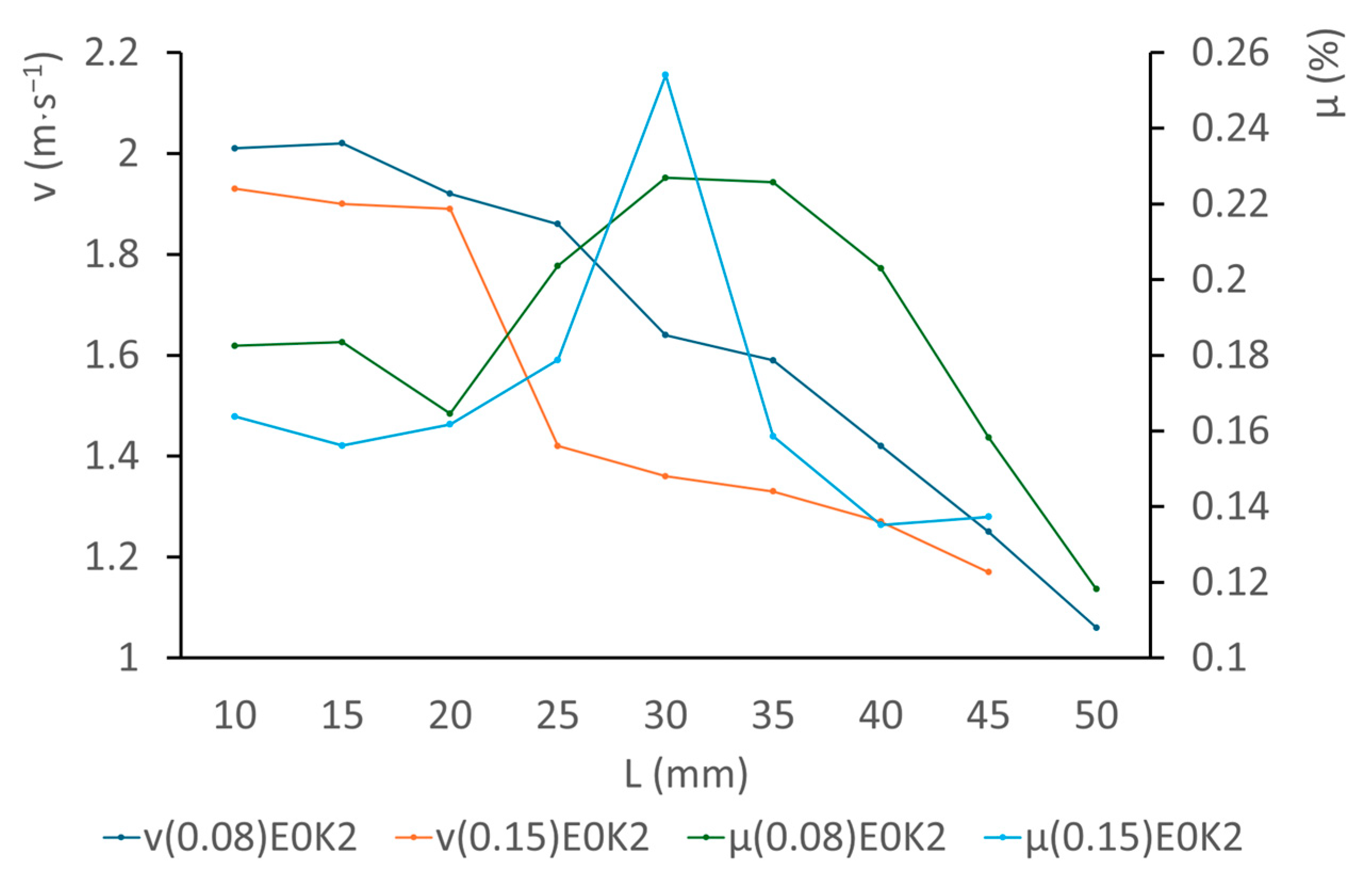
Despite the local efficiency peak (
Figure 6), induced by the antagonistic effects of the growing inter-electrode distance of the (0.15)E0K2 system, the highest average value of efficiency (0.185%) was achieved with the (0.08)E0K2 system. At all of the inter-electrode distances, the instantaneous output speed of the accelerated medium was higher with the (0.08)E0K2 system.
The purpose of the second series of experiments was to examine the effect of the effective length of the electrodes on the propulsion parameters. Despite the fact that increasing the effective length of the electrodes generally leads to an increase in the active surface area for the ionisation and transfer of charge, a dense arrangement of the electrodes may trigger negative physical processes that have negative effects on the propulsion parameters.
When the distance between the adjacent emitters (corona electrodes) is too short, it results in mutual interference and a superposing of the electric fields.
With a dense configuration, a high concentration of charge carriers is formed in the gap between the electrodes, especially at a high voltage. Such conditions contribute to the recombination of ions and electrons, so that a part of the produced charge is neutralised before it may contribute to the generation of a propulsion force. As a result, the net current decreases and so does the propulsion efficiency.
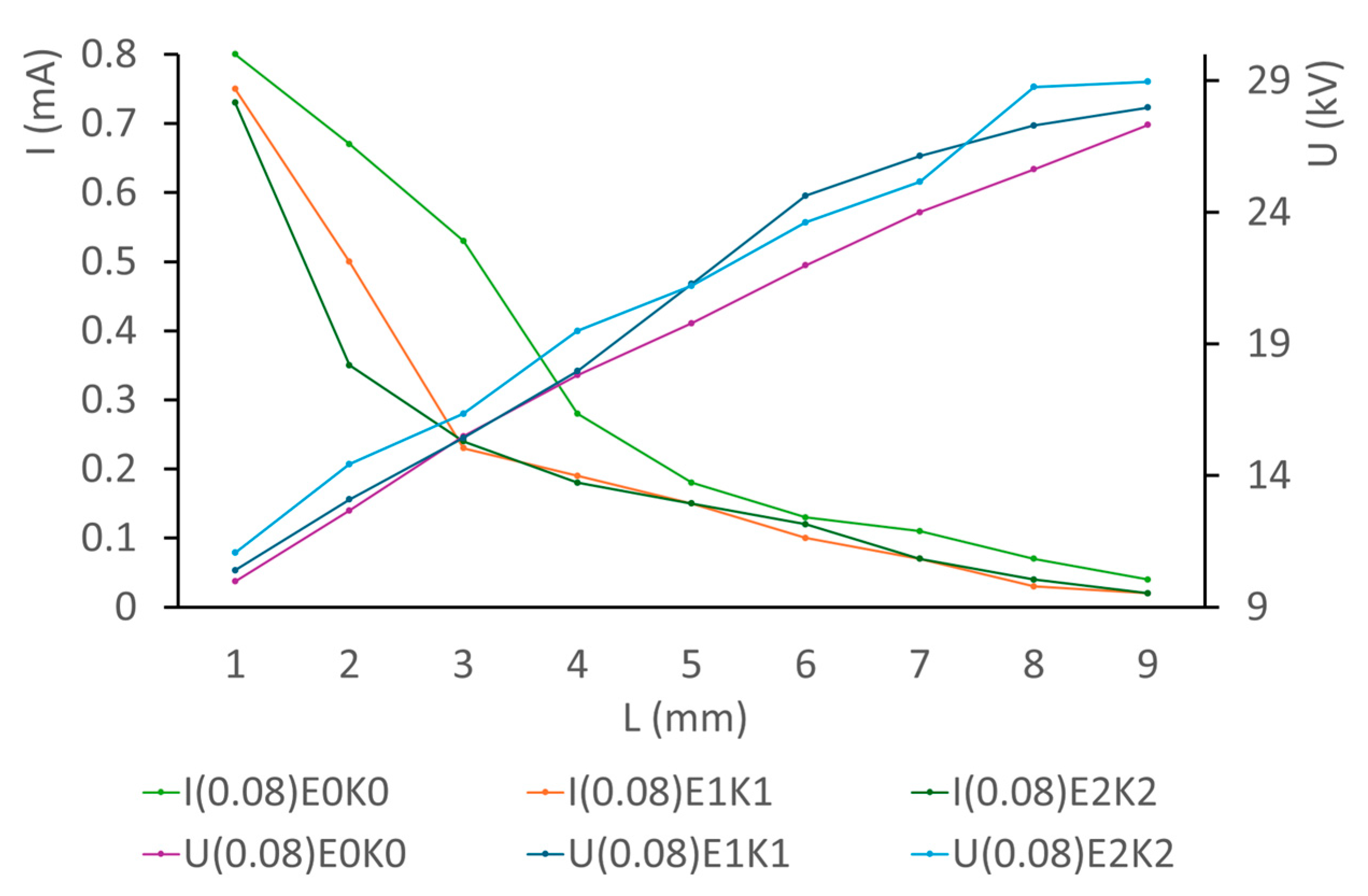
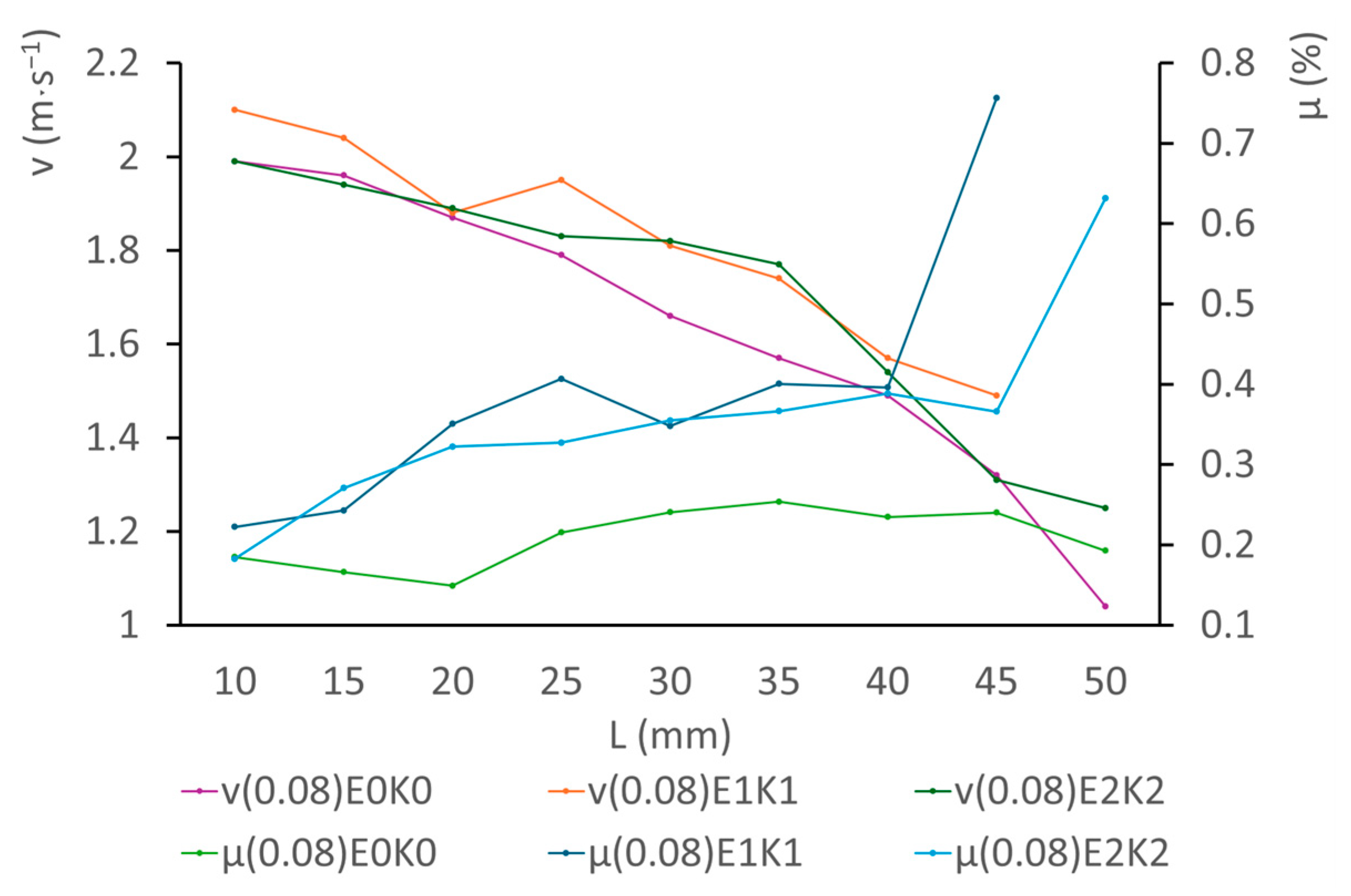
As was initially hypothesised (
Figure 7), the highest instantaneous values of the electric current flowing between the electrodes were achieved, in all of the cases, with the (0.08)E0K0 configuration. In a proximal vicinity, in terms of the electric current, the (0.08)E1K1 configuration dominated over the (0.08)E2K2 configuration. The voltage required for the initiation of a corona discharge was the lowest with the densest composition—(0.08)E0K0—with all of the applied inter-electrode distances. The highest average voltage required for triggering a corona discharge was needed with the system having the least dense arrangement—(0.08)E2K2.
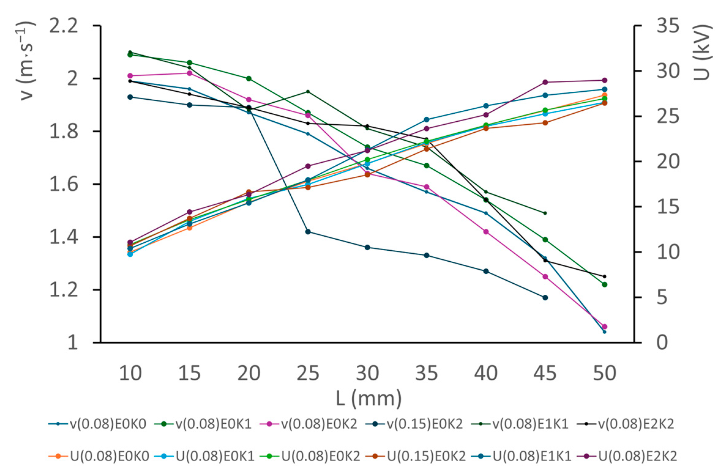
Further, the velocity–voltage characteristics were compared for all inter-electrode distances (
Figure 8).
An extreme speed of 2.1 m·s
−1 was achieved with the (0.08)E1K1 configuration, at the inter-electrode distance of 10 mm (
Figure 9). With the same composition, the highest achieved efficiency was 0.756%. The composition with the high density (0.08)E0K0 achieved the lowest efficiency at all of the applied inter-electrode distances. This composition also exhibited a trend for the lowest average output speed of the accelerated medium.
The effects of the inter-electrode distance were observed in both series of experiments. The distance between the emitting and collecting electrodes ranks among the crucial geometric parameters that affect the critical parameters of electrohydrodynamic propulsion. This distance directly determines the intensity of the electric field in the gap between the electrodes. With a shorter distance, and with an identical magnitude of the voltage supplied to the terminals, the electric field formed exhibits a higher intensity, which facilitates the initiation of a corona discharge and supports the efficient ionisation of the surrounding medium. By contrast, with a longer distance, it is necessary to apply a higher voltage in order to achieve a similar or an identical field intensity.
As for the electric current, with longer distances between the electrodes, the current density in the discharge region decreases. This means that the amount of the electric charge flowing through the system per time unit is lower, which has negative effects on the total propulsion efficiency.
By reducing the distance between the electrodes, the parasitic capacitance and the leakage current increase, which results in higher energy losses in the system. Such a phenomenon indirectly causes a lower efficiency of the conversion of electric energy to kinetic energy in the accelerated medium.
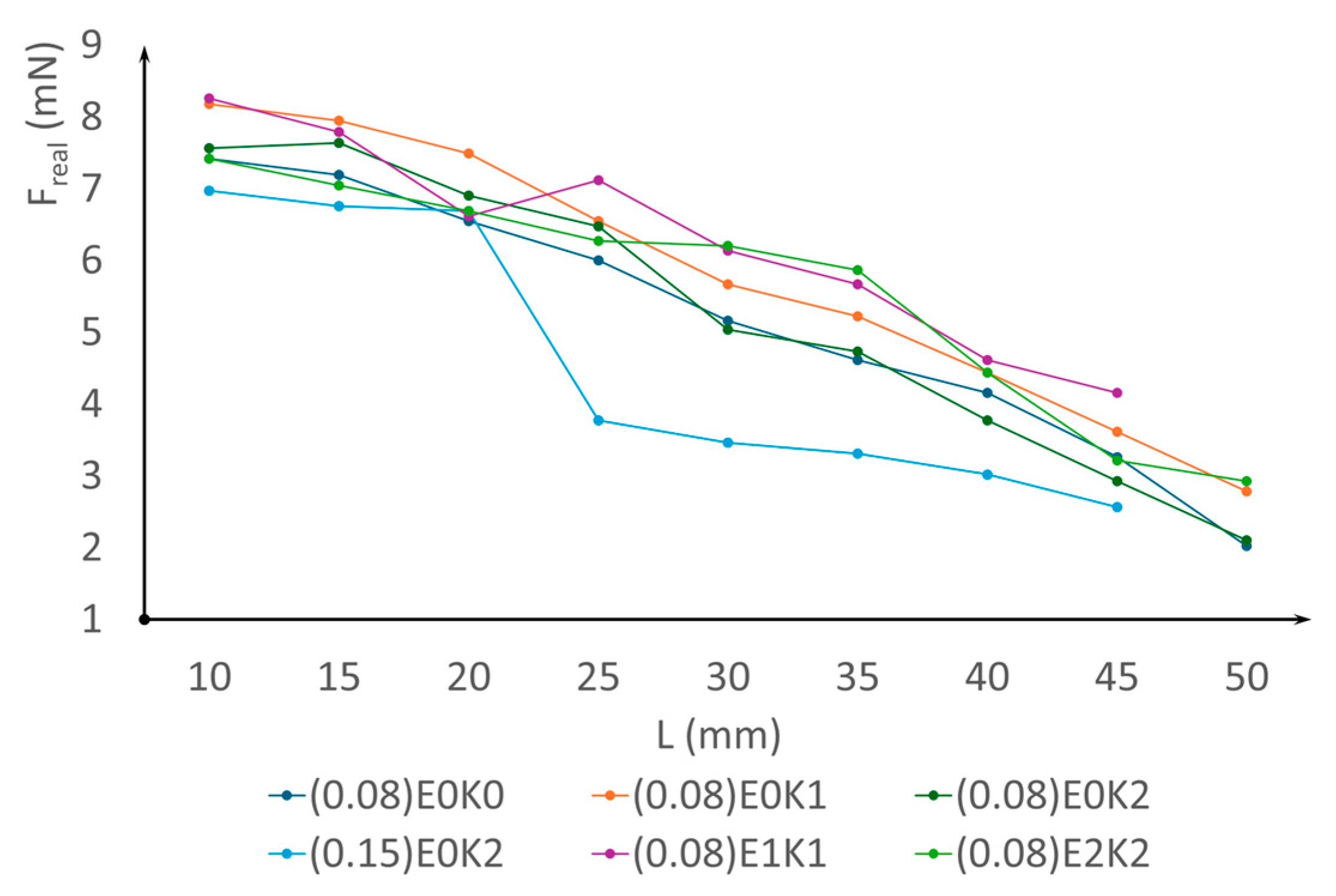
The most significant parameter observed was the thrust (
Figure 10), which increased with the square of the outlet velocity at the same flow cross-section and a constant medium density.
6. Conclusions
The results of the conducted experiments and of the analyses of the values obtained in the experiments clearly confirm that electrohydrodynamic (EHD) propulsion is a promising technology for generating a thrust, which is applicable in atmospheric conditions.
All the experimental measurements were conducted while a positive polarity was applied to the emitting electrode. Such a configuration was selected due to the higher stability of the corona discharge and the lower probability of undesired discharge phenomena, compared to a negative polarity.
All of the measurements were carried out within a period of several hours, during which the atmospheric parameters were not subjected to any significant changes. Therefore, the atmospheric conditions were regarded as quasi-stationary, and their effects on the results were assessed as negligible.
The experimental results confirmed that the output speed of the accelerated medium and the propulsion efficiency significantly depend on the following:
- -
The diameter of the conductor of the corona electrode. With an increasing conductor diameter, the initiation threshold voltage of the electric field’s critical intensity that is required for triggering a stable corona discharge also increases. This phenomenon led to a decrease in the current density in the gap between the electrodes in the asymmetrical capacitor, which subsequently manifested as a decrease in the outflow speed of the medium.
- -
The effective length of the electrodes, since it intensively affects the critical propulsion parameters, including the output speed of the accelerated medium and the efficiency. As the length increased, the total current density in the system also increased due to an increase in the active surface area for the transfer of charge. On the other hand, however, longer electrodes caused a dispersion of the electric field and a decrease in its intensity in critical regions, which may have reduced the efficiency of the ionisation and electrostatic acceleration of the charged particles. Moreover, the application of longer electrodes led to higher parasitic losses, due to the recombination of ions or interactions with the surrounding surfaces. Negative effects were also observed for the aerodynamic resistance in dense-arrangement topologies.
- -
The effect of the inter-electrode distance. As the inter-electrode distance increased, the electric potential gradient decreased. Such a lower intensity impaired the forces exerted on the present ions. On the other hand, however, the longer inter-electrode distances led to an increase in the volume of the air for polarisation, which led to a higher speed of the accelerated medium. The interactions between these two opposite phenomena explain the shapes of the curves depicted in the graphs.
The maximum speed of the outflowing medium presented in this article, achieved in the one-stage configuration consisting of the (0.08)E1 emitter and the K1 collector, amounted to 2.1 m·s−1. With an identical diameter of the conductor of the corona electrode and a fixed inter-electrode distance of 50 mm, this design topology exhibited the highest system efficiency at 0.756%.
The potential to extend the range of applications of technologies based on EHD propulsion is significant; therefore, further research should focus on optimising the topology of the electrodes and reducing energy losses, as well as studying the nonlinear processes in the field of the corona discharge and the transport of the charge in various pressure and temperature conditions.
An issue that remains unsolved relates to inter-electrode punctures at short inter-electrode distances, as well as the miniaturisation of those systems. The output of the conducted experiments is a compact set of data describing a correlation between the propulsion parameters and the shapes and geometry of the electrode systems. In our future research, we plan to implement the knowledge obtained in the field of mobile propellers.
