Review

Review of Crack Depth Detection Technology for Engineering Structures: From Physical Principles to Artificial Intelligence

1
The Road Transport Service Center of Jiaozuo City, Jiaozuo 454002, China
2
School of Energy Science and Engineering, Henan Polytechnic University, Jiaozuo 454003, China
*
Author to whom correspondence should be addressed.
Appl. Sci. 2025, 15(16), 9120; https://doi.org/10.3390/app15169120
Submission received: 10 July 2025 / Revised: 7 August 2025 / Accepted: 8 August 2025 / Published: 19 August 2025
(This article belongs to the Special Issue Research on Machine Learning in Computer Vision)

Abstract

Ensuring the structural safety of components or facilities is essential for the smooth operation of industrial production and transportation. As a key index to evaluate structural health, the crack depth detection method has evolved from the early single physical field detection to the contemporary multi-physical field collaborative artificial intelligence algorithm. This paper presents a systematic review of crack depth detection technology under specific engineering conditions, such as those found in roads, train tracks, and engine blades. The framework categorizes and reviews detection technology according to detection principles, including physical principles, model inversion, hybrid methods, and evaluation indicators such as detection accuracy, speed, and cost. The paper compares various detection technologies, highlighting their advantages and limitations in real-world applications. The analysis reveals key challenges, which include complex environmental interference, the detection of microcracks and deep cracks, and the balance between accuracy and cost. Addressing these challenges is imperative to improving the reliability and generalization of detection technology. This paper proposes future research directions focusing on integrating multi-physical field detection with artificial intelligence, utilizing AI’s robust capabilities to develop more advanced methods for detecting crack depth.

1. Introduction

Engineering structures (such as roads, bridges, pipelines, and aerospace components) are prone to cracking due to fatigue, corrosion, or mechanical loads during long-term service. If these cracks are not detected on time, they may lead to catastrophic consequences. For example, the propagation of transverse cracks in steel rails [1,2] will directly affect transportation safety. The propagation of cracks in aircraft engine blades [3] threatens flight reliability. The expansion of concrete cracks [4,5] can limit the stability of buildings. Crack depth, as a core parameter for evaluating the degree of damage to an object, is a critical basis for predicting the remaining life of a structure and formulating subsequent maintenance strategies. Detection and evaluation of crack depth can avoid severe consequences caused by sudden structural failures. However, existing crack detection technologies face three challenges: firstly, insufficient detection accuracy (deep-buried cracks or complex conditions will affect the accuracy of ultrasonic testing (UT) [6]); secondly, limited applicability scenarios (infrared thermal imaging detection sensitivity depends on factors such as materials and natural environment [7]); and finally, high implementation costs (phased array radar [8], laser ultrasonic technology [9]). Therefore, systematically reviewing the principles and limitations of existing detection technologies and exploring innovative interdisciplinary methods are expected to develop more accurate, efficient, and intelligent crack depth detection technologies or systems. Accurately detecting and evaluating crack depth can prevent safety accidents and have essential theoretical value and engineering significance for improving engineering structural safety monitoring.
The evolution of crack depth detection technology has experienced two different technical stages. Early detection has mostly relied on a single physical property: the detection method of measuring the change in ultrasonic propagation time, amplitude, and frequency in the crack [10]. By detecting the distribution and intensity of eddy currents induced in conductive materials, the location and depth of cracks are inferred [11]. An infrared thermal imager is used to capture the infrared radiation of the material surface, which is converted into a temperature distribution image and identified according to the difference between the temperature of the crack area and the surrounding area [12].
Subsequently, high-precision detection methods based on more advanced sensing technology have evolved. The vector network analyzer measured the resonant frequency of the patch antenna sensor, and the influence of different damage parameters on the detection performance of the sensor was evaluated [13]. Ultrasonic array shear wave detection equipment was developed to rapidly detect the crack depth of the opening on the concrete surface using the imaging method of crack focusing synthetic aperture focusing technology (CF-SAFT) [14]. At the same time, the detection method combined with an artificial intelligence algorithm has been gradually applied to the industrial field. A pixel-level road crack detection method based on u-shaped convolutional network for unmanned aerial vehicle (UAV) remote sensing images was proposed by combining deep separable convolution, an attention mechanism, and multi-scale feature extraction technology [15]. A deep learning architecture for pixel-level crack segmentation was proposed by fusing multilevel features with dense convolution layers and removing isolated noise pixels using the DFS algorithm [16]. Combined with discrete wavelet transform (DWT) denoising and adaptive neuro-fuzzy inference system (ANFIS) recognition, a method for crack detection of the rotor bearing system [17] was proposed. We have drawn the evolution diagram of crack depth detection methods in chronological order, as shown in Figure 1.
This paper aims to comprehensively review the evolution and frontier progress of crack depth detection technology, covering a variety of means from traditional physical-driven methods to emerging data-intelligent driven models. Through systematic classification and critical analysis, it will provide a scientific basis for selecting crack depth detection methods for different engineering scenarios (such as aerospace, civil infrastructure, industrial manufacturing, etc.) and reveal the potential direction of future research. The contributions of this paper are as follows.
Firstly, we break through the limitations of traditional single technology route reviews, cover the conventional and emerging detection technologies, and analyze their principles, advantages, disadvantages, and applicability.
Secondly, we compare the key technologies of the existing research on crack depth detection, and summarize the existing core challenges, to provide a reference for follow-up research.
Finally, we analyze the future research direction and provide a theoretical reference for interdisciplinary research.
The organizational structure of the remaining parts of this paper is as follows. The second part is the classification and review of crack depth detection technology. The third part is a comparison of technology and key challenges. The fourth part is the future research direction. The last part is the conclusion.
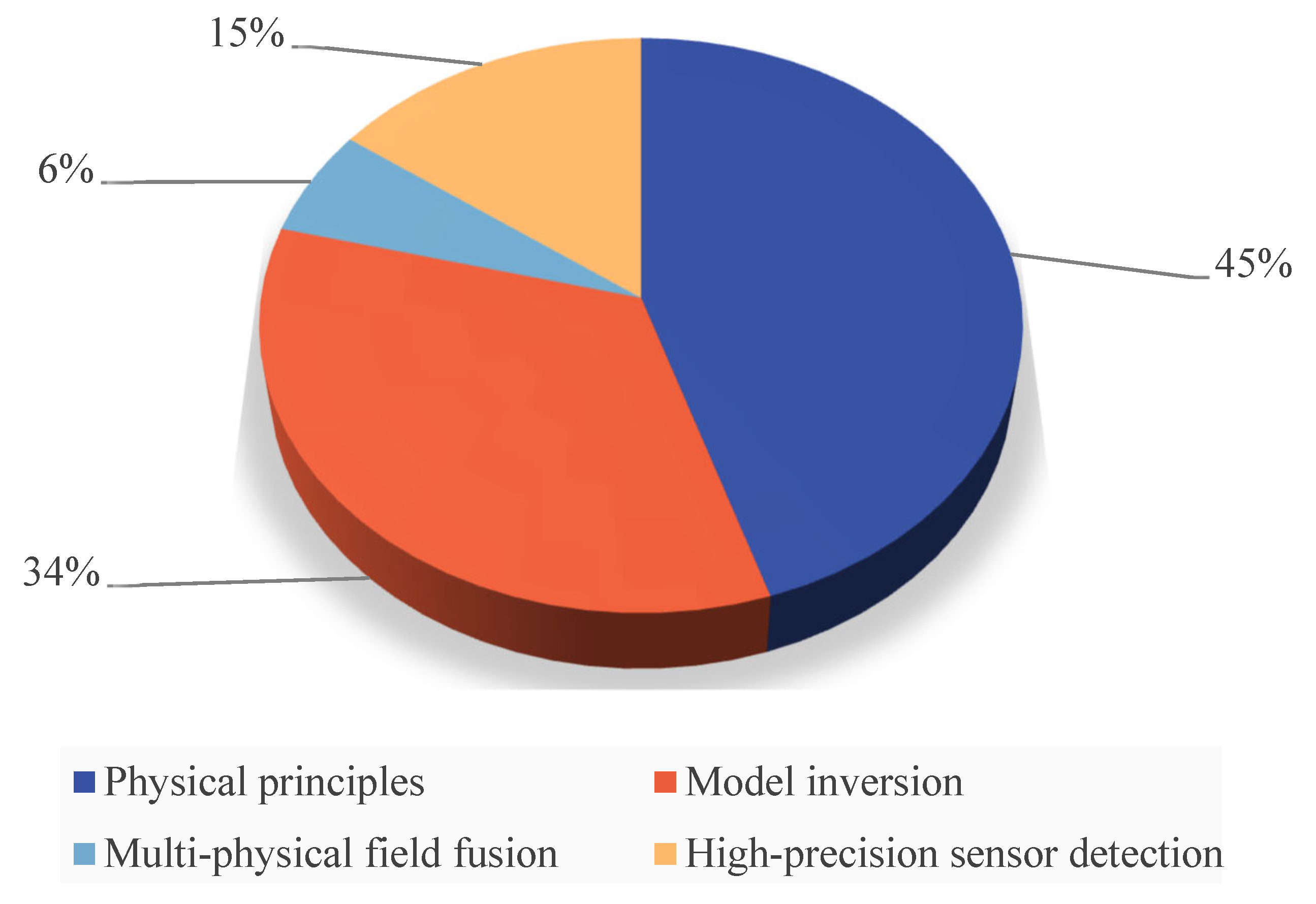
We conducted keyword searches on Web of Science to select as many reference articles as possible from 2016 to 2025, and we obtained 70 references. By reading and analyzing 70 reference articles, we systematically summarized the detection methods used in each article. When classifying the detection methods of literature, only the core methods of the literature are considered, and a literature study may be classified into multiple categories. The detection methods are divided into four categories: physics-based detection methods (61 articles), model inversion-based methods (46 articles), high-precision sensor detection (20 articles), and multi-physical field fusion detection (8 articles), with a total of 135 occurrences. We calculate the number and proportion of various categories of literature as shown in Figure 2.

2. Classification and Review of Crack Depth Detection Technology

2.1. Detection Method Based on Physical Principle

The detection method based on physical principles realize depth quantification by capturing the changes of physical properties such as sound, light, electricity, and heat caused by cracks. It mainly includes UT [4,6,10,18], ECT [19,20], infrared thermal imaging [12,21,22,23,24], optical testing [2,25], and magnetic detection [26,27,28,29].
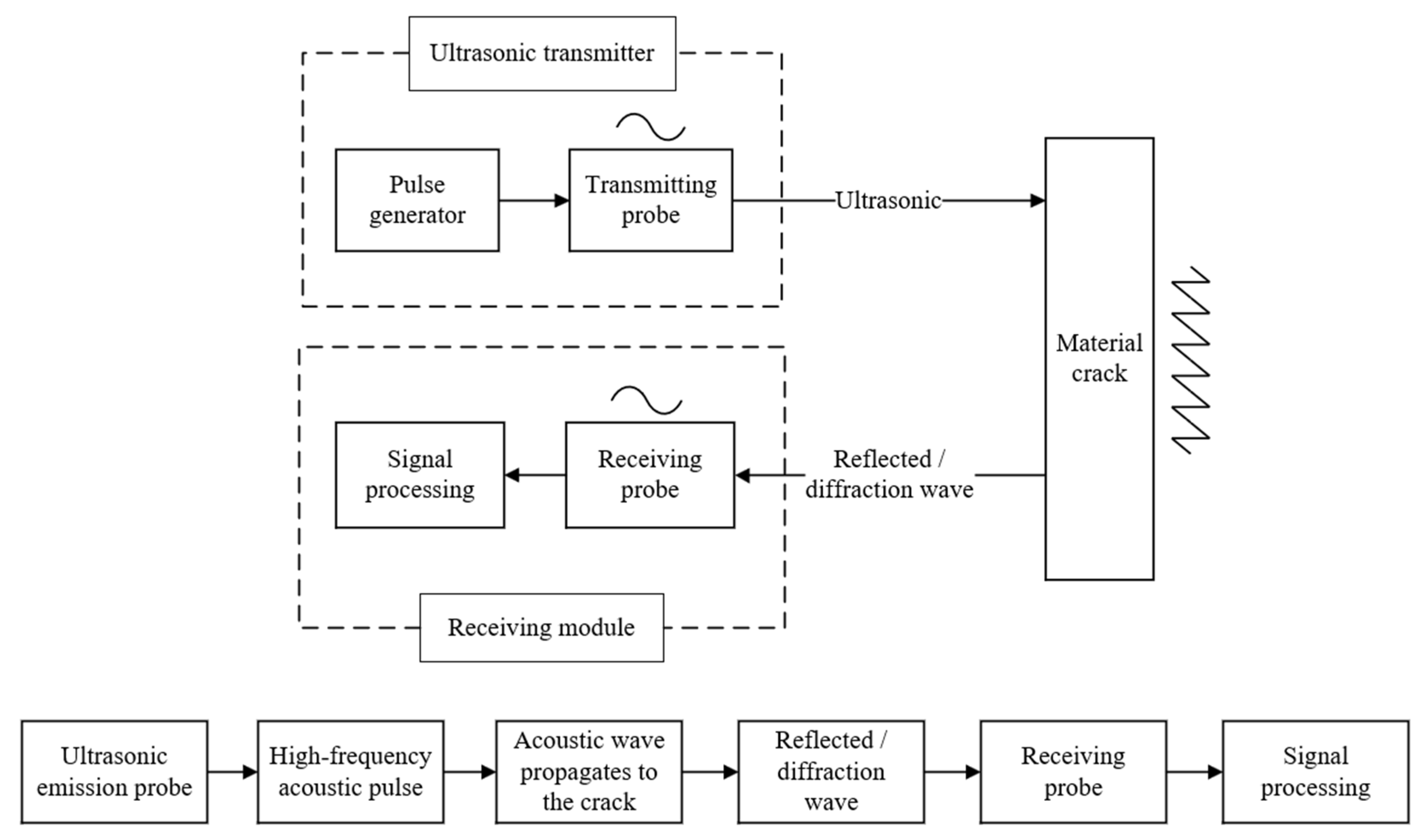
UT determines the location and depth of cracks by measuring parameters of the reflected wave generated at the crack. The detection process is shown in Figure 3. Chen et al. [21] used the double-probe ultrasonic detection method to detect the prefabricated crack specimens of flat steel. Based on the geometric relationship calculation and experimental results, they developed a method to determine the crack tip position and analyzed the detection accuracy of the double-probe penetration method.
ECT analyzes the change in eddy current in materials according to the principle of electromagnetic induction. The detection process is shown in Figure 4. Xu et al. [30] proposed a high-speed railway track crack detection method based on differential eddy current detection technology and established the relationship between crack depth and detection speed by analyzing the amplitude and phase changes of the ECT signal.
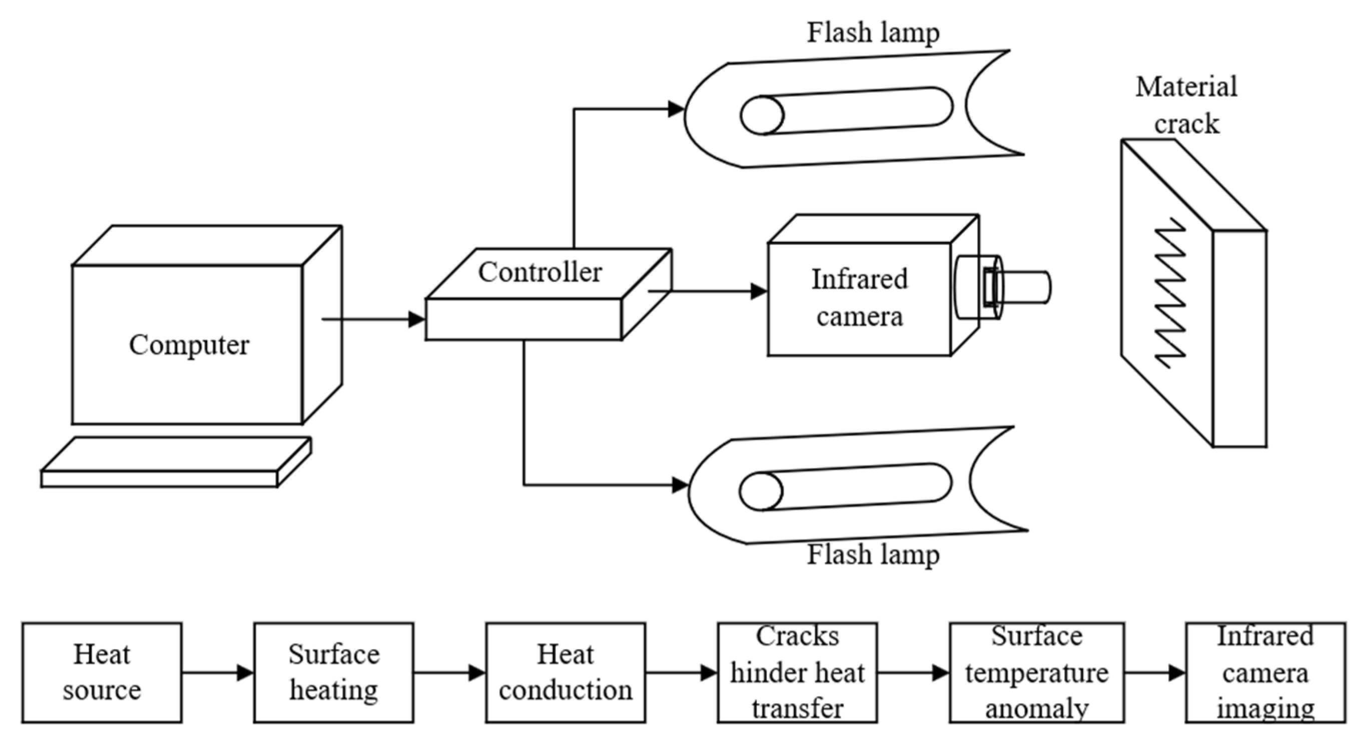
The infrared thermal imaging method identifies internal defects by capturing changes in the object’s surface temperature field. The detection process is shown in Figure 5. Oswald-Tranta et al. [7] used short-pulse induction to heat the sample, recorded the temperature distribution through the infrared camera, and converted the temperature change with time into phase information to realize the detection of cracks and the estimation of depth.
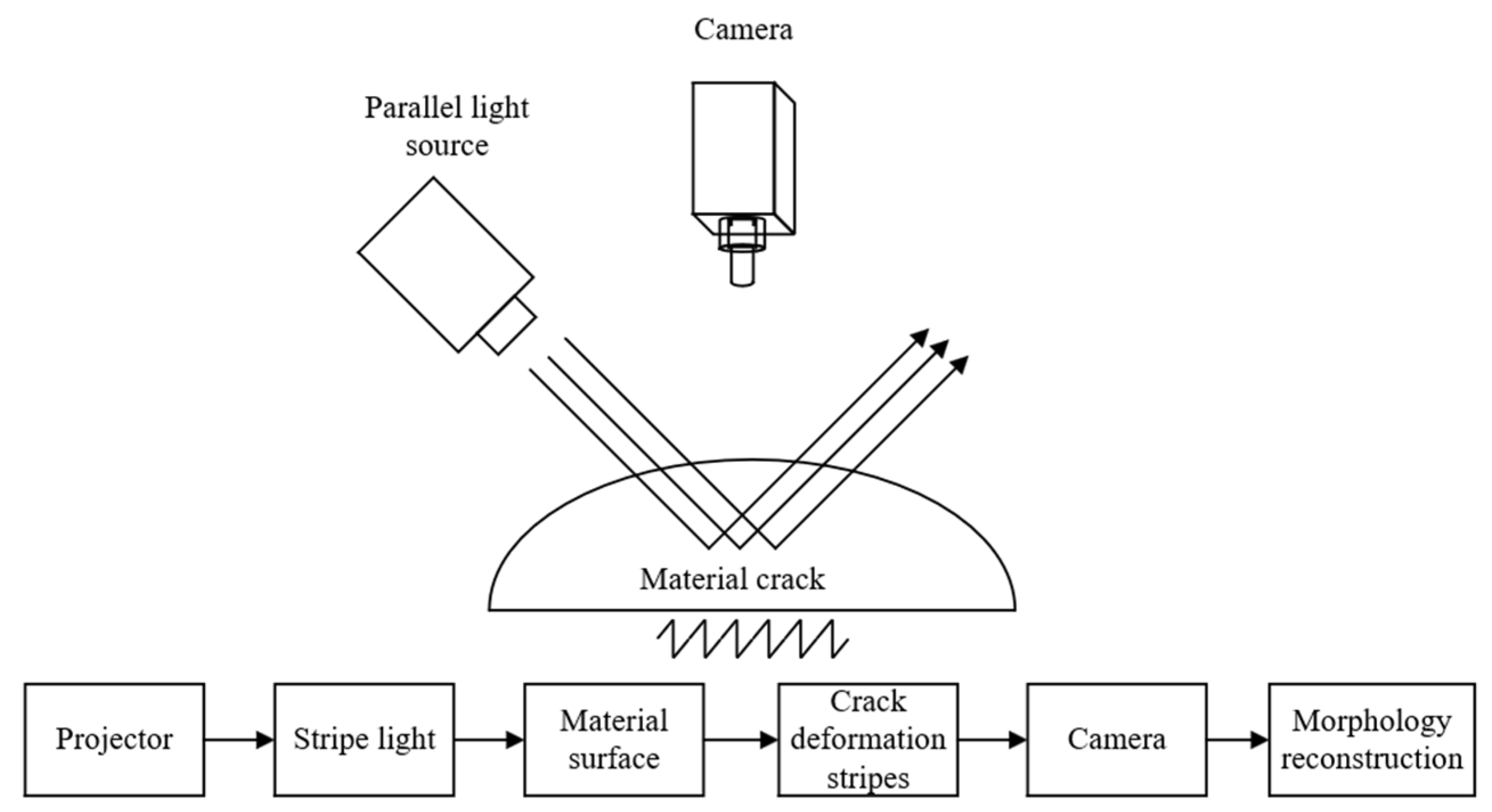
The optical detection method obtains the depth and shape of the crack by analyzing the change in the optical signal. The detection process is shown in Figure 6. F. van ‘t Oever et al. [25] used the laser scanning system to collect the 3D profile data of the road. They identified and extracted the cracks by analyzing the object features in the 3D profile data, combined with the tensor voting algorithm.
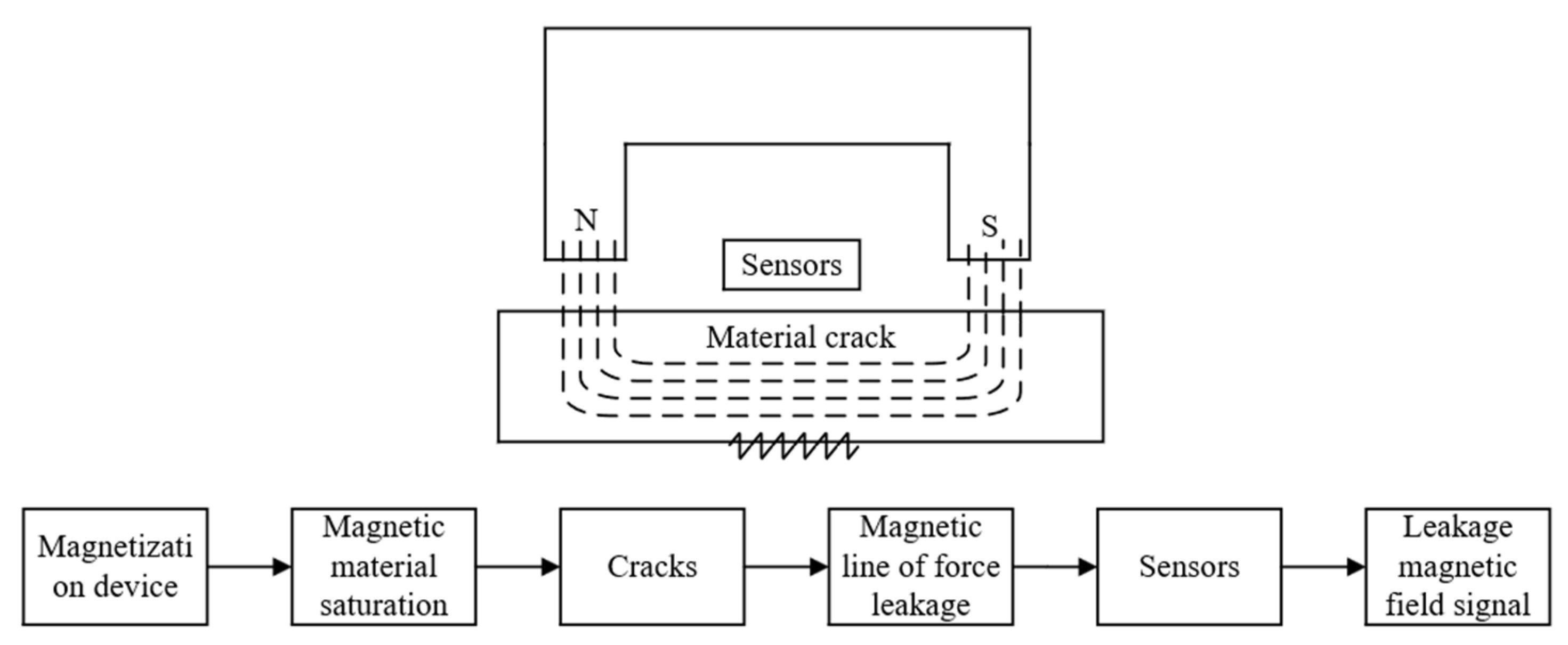
Magnetic detection evaluates the crack depth by analyzing the magnetic field distortion after magnetization of the material. The detection process is shown in Figure 7. F. Yuan et al. [31] used direct-current electromagnetic non-destructive testing (NDT) technology to establish the relationship between crack inclination angle, depth, and detection signal for moving ferromagnetic materials so as to evaluate the direction of rolling contact fatigue (RCF) crack.
In general, when conducting crack depth detection on engineering sites, the detection results based on physical principles will be affected by various factors, including the external environment and working conditions. Changes in temperature and humidity can affect the detection results of infrared thermography. Dust and backlighting may interfere with the imaging effect of cracks during optical detection, as well as the inspected materials and structural properties. UT usually requires a smooth surface of the material or the use of coupling agents to ensure testing effectiveness. ECT is suitable for conductive materials, especially non-magnetic materials. Magnetic testing requires that the tested material be ferromagnetic. In addition, the physical constraints of the method itself are also one of the factors that affect the detection results. The wavelength limitation in UT, the obstruction of light in optical testing, and the weak detection signal of cracks parallel to the flow direction of eddy currents in ECT may all affect the accuracy of the detection results. In a single physical field, it is still challenging to solve the problem of multi-scale crack detection under complex working conditions. It is necessary to integrate multimodal signals to overcome technological bottlenecks.

2.2. Model-Based Inversion Method

The model-based inversion method realizes depth prediction by establishing a quantitative relationship between crack depth and the detection signal, which mainly includes an analytical model [32,33,34,35,36,37] and a data-driven model [38,39,40,41,42,43,44,45].
The analytical model is based on physical laws (such as elastic mechanics and electromagnetic theory) [26] to construct mathematical equations through numerical simulation, finite element simulation, and other methods. The detection process is shown in Figure 8.
Chen et al. [9] simulated the interaction between cracks with different depths and lengths and Rayleigh waves through numerical models, extracted key parameters such as center frequency, and quantitatively detected lateral subsurface cracks based on a frequency domain analysis method, which can simultaneously measure the depth and length of cracks. Wang et al. [46] used the finite element method to establish a numerical model of the interaction between laser-generated Rayleigh waves and subsurface cracks and quantitatively estimated the size of cracks by analyzing the frequency characteristics of Rayleigh waves under different crack sizes.
The data-driven model builds the corresponding model by learning the complex relationship between the input characteristics and the output results from the data. The detection process is shown in Figure 9.
In the process of using a data-driven method based on pulsed eddy current (PEC), Tian et al. [47] proposed a data-driven method based on PEC. This method uses a PEC detection system to obtain a large amount of detection data. Introducing the Jarque–Bera (JB) statistical test and principal component analysis (PCA) method, it can improve data processing efficiency and extract the main features. Wang et al. [48] combined the laser acoustic emission technology with multivariable feature adaptive extraction, cross-modal interactive fusion, and deep learning to build a crack depth detection network (CDDNet) to achieve the extraction and detection of crack depth features. Similarly, Dong et al. [49] proposed a new network architecture, snf-yoyov8, for surface cracks of large stamping parts, combining a convolution space depth module and visual self-attention mechanism, which can effectively detect small-sized cracks and improve detection speed.
These two methods are complementary, and the analytical model takes physical laws and mathematical equations as its core, providing interpretable and generalizable physical priors for data-driven models (for example, inputting ultrasound response data obtained from finite element simulation as features into neural networks [50] can effectively reduce its dependence on large-scale field data). Analytical models typically rely on assumptions such as homogeneous media and ideal boundaries, and once they encounter complex engineering environments, their analytical errors will rapidly amplify. In the context of multivariate coupling, data-driven models automatically capture high-dimensional and nonlinear mapping relationships that are difficult to model explicitly through learning, thereby transforming the blind spots of the analysis model into learnable dimensions [48].
The future trend is more inclined to integrate multi-physics field information with data-driven models [5] and quickly generate a large amount of labeled simulation data through lightweight analysis models to solve the problem of scarce on-site truth values. Using data-driven models to output residuals, one can reverse-adjust the analytical model’s boundary conditions and material parameters and achieve model calibration. The ultimate goal is to achieve higher accuracy and cross-scenario generalization ability while maintaining physical interpretability.”

2.3. High-Precision Sensor Detection and Multi-Physics Field Fusion Detection

Multi-physical field fusion detection integrates acoustic, optical, electrical, thermal, and other multi-dimensional signals [19,51,52], aiming to break through the limitations of traditional single physics field detection and improve detection accuracy and adaptability under complex working conditions. Qiu et al. [53] used eddy current pulse thermal imaging (ECPT) technology to study tensile stress’s effect on the quantitative detection of crack depth in ferromagnetic materials. This method can simultaneously detect the existence of cracks and quantitative crack depth and applies to a variety of ferromagnetic materials. Wang et al. [5] combined the tracer electromagnetic method with complex signal analysis technology to improve radar signal interpretation accuracy and overcome the interference problem of traditional techniques in complex internal structures, and it can more accurately detect the depth and shape of internal cracks in concrete.
Advanced sensing technology, with its high sensitivity to capture weak physical signals, provides a reliable data foundation for high-precision crack depth detection [40,54,55]. Zhang et al. designed a sensor based on the transmission line. By adjusting the parameters of the transmission line, the working frequency and bandwidth of the sensor can be flexibly designed. At the same time, the magnetic field distribution is limited by loading high dielectric constant materials to improve the sensor’s sensitivity to cracks [56]. Liu et al. developed a patch antenna sensor, which quantifies the crack size under the coating by frequency offset and promotes real-time monitoring with a miniaturized and distributed sensor network [13]. Xie et al. [57] proposed a crack monitoring method based on an ultra-high frequency (UHF) RFID antenna sensor. The sensor is composed of two coupled ring resonators. The outer ring is used for radiation and sensing, and the inner ring is used for impedance matching. This method can detect cracks in different positions and directions and achieve high-sensitivity detection of crack depth and width.
These two technologies form a collaborative closed loop. Advanced sensing technology provides high-precision and high-sensitivity data acquisition methods for multi-physics field fusion detection, improving the accuracy and reliability of multi-physics field fusion detection (such as the combination of laser acoustic emission and CDDNet [48]). Multi-physics field fusion detection can fully leverage the performance of advanced sensing technology, expand its application scope, and provide a broad demand space for advanced sensing technology. The future trend focuses on embedded intelligent systems (such as a particle swarm optimization sensor–algorithm joint design [50]) to achieve full-chain optimization from data acquisition to depth inversion.
The structure of different detection methods is shown in Figure 10.

3. Technical Comparison and Key Challenges

3.1. Performance Index Comparison

The performance of crack depth detection techniques is significantly different, mainly due to the apparent differences in the physical principles or model characteristics on which they are based. UT can achieve fast, high sensitivity and penetration detection by analyzing acoustic signals such as reflection and refraction [6,9,46]. Still, the detection range is limited and sensitive to material properties, a coupling agent is needed, and the cost is high. ECT [30,47] has the advantages of fast detection speed, high sensitivity, and no coupling agent for the crack detection of conductive materials. Still, the detection depth is limited and susceptible to environmental factors. An infrared thermal imaging method [3,7,58] can quickly locate cracks through thermal imaging, which is widely used and visually displayed, and can be used for all-weather monitoring. However, the detection depth is limited and easily affected by environmental factors, so overcoming the key technical bottlenecks is necessary. Optical detection [49,59,60] identifies the existence and characteristics of cracks through optical imaging technology. Still, it is more sensitive to the environment, has limited detection depth, and has poor adaptability to complex surfaces. Magnetic detection [32,61] locates the location of defects by detecting the anomaly of the magnetic field, which has the advantages of fast speed, high sensitivity, low cost, and visual display. However, the detection depth is limited to magnetic materials, and the surface needs to be preprocessed. The analytical model [1,3,4] predicts the location and depth of cracks through mathematical models and numerical simulations. It has high precision and is suitable for complex structures, but the detection speed is slow and the dependence on data and models is strong. The data-driven model [62,63,64] learns the relationship between crack features and depth from a large amount of data, which has high accuracy, robustness, and scalability. However, the model’s interpretability and cross-scene generalization ability are poor depending on the quality and quantity of labeled data. In general, high-precision technologies (UT, infrared thermal imaging, data-driven models) often require complex equipment or precision algorithms, accompanied by environmental or cost constraints, while fast and low-cost solutions (ECT, magnetic testing) are simple and suitable for real-time monitoring; however, there are limitations in accuracy and material applicability. The specific performance indicators are compared as shown in Table 1.

3.2. Key Challenges

In practical engineering applications, crack depth detection technology not only needs to overcome the technical bottleneck of limited detection accuracy but also faces external constraints that hinder its large-scale promotion. The reasons affecting self-detection accuracy include complex environmental interference, small cracks, and deep-buried cracks. The factors that impede the promotion of crack depth detection technology can be summarized as insufficient model generalization ability, high accuracy, and cost issues.
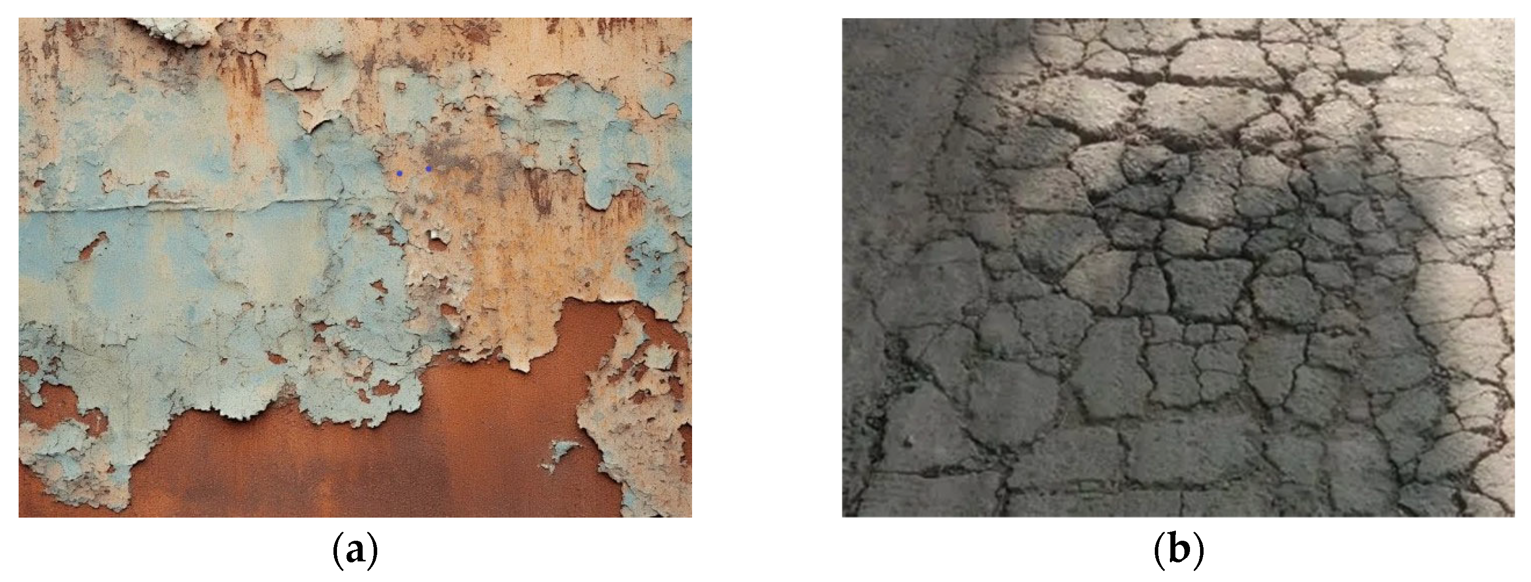
Complex environmental interference: Cracks in complex environments are shown in Figure 11. In the actual detection, the detection effect based on physical principle is often restricted to varying degrees in the face of a complex and changeable environment. For example, in complex environments such as corrosion, strong light or shadow, electromagnetic interference, or multi-layer structure, these physical model-based detection methods may cause problems such as inherent defects of detection methods, signal interference, or difficulty in feature extraction, resulting in a decline in the accuracy and stability of detection results, which is challenging to meet the requirements for detection accuracy and reliability in actual engineering scenarios. Generally, the materials with rough surfaces or severe corrosion may cause unexpected scattering and reflection of sound waves, which will distort and clutter the received signals, affecting the results of UT [4]. In addition, strong light or shadow will affect the overall quality of the image, making it difficult for optical detection equipment to accurately capture and analyze the characteristics of the target object, which will lead to the deviation of the detection results and affect the accuracy of optical detection [59]. Electromagnetic interference affects regular operation of the sensor, distorting or losing of the detected signal, and then affects the accuracy of ECT and magnetic testing [60,64]. The difference in acoustic impedance and anisotropy of heat conduction in composite materials or multi-layer structures will lead to the confusion of acoustic or thermal signals, which increases the difficulty of crack depth interpretation [6,8].
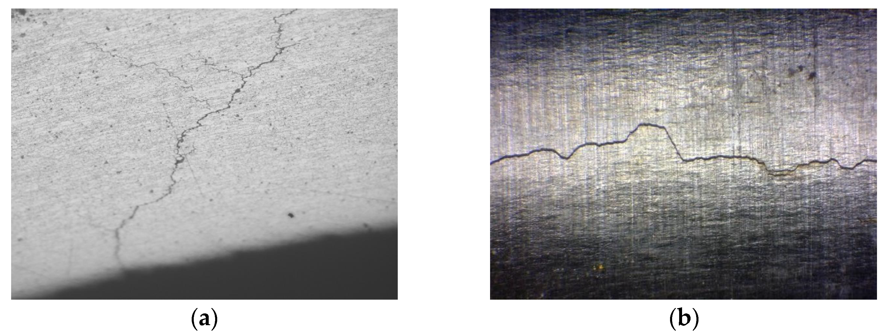
Microcrack and deep-buried crack detection: Microcracks and deeply buried cracks are shown in Figure 12. The inherent characteristics of the physical field limit the traditional method. For example, when the crack size is much smaller than the ultrasonic wavelength, the ultrasonic beam cannot effectively focus on the micron-level crack due to the wavelength limit, resulting in the decline of the strength and resolution of the detection signal, thus significantly reducing the detection sensitivity [18]. Because the thermal signal intensity of deep-buried cracks will be significantly diluted after diffusion, the thermal signal characteristics will weaken when reaching the material surface. At this time, when the infrared thermal imaging equipment is used for detection, the received thermal signal has become blurred and indistinct, which cannot reflect the existence and characteristics of deep-buried cracks, so the infrared thermal imaging method has low detection sensitivity for deep-buried cracks [22]. In addition, due to the limited penetration of light, it is mainly concentrated in the near-surface area of the material. The optical detection method cannot obtain adequate reflection or scatter signals for the cracks deeply embedded in the material. Therefore, optical detection can only detect the cracks on the surface of the material, but when facing deep-buried cracks, it cannot provide any characteristic information about the cracks [25].
The generalization ability of the model is insufficient. In building the analysis model, some complex parameters are usually idealized due to the limited grasp of the actual situation or to simplify the problem for easy calculation. In the actual situation, many factors will affect these parameters, such that the prediction results of the model cannot fully and accurately reflect the exact problem, resulting in the generation of prediction error and the limitation of generalization ability. In practical applications, the data-driven model shows relatively fragile characteristics in cross-scenario applications. Taking the deep learning model trained based on metal crack detection as an example, because of the huge differences between metal and concrete in physical properties, surface characteristics, and crack formation mechanism, the features learned by the metal model are not suitable for concrete crack detection [48,65]. In addition, data-driven models usually need a large amount of labeled data for training and then learn the effective features in the data. In the small-sample scenario, due to the lack of sufficient labeled data, the model is challenging to understand and generalize effectively, which affects its performance and accuracy. This cross-scenario inadaptability and dependence on the amount of data show some limitations of the data-driven model in practical applications [67].
High precision and cost balance: In the field of crack depth detection, high-precision detection technologies such as optical coherence tomography [2] and phased array ultrasonic technology [8] perform well in detection accuracy, but their instruments are relatively expensive, which limits their wide application to a certain extent. In contrast, some low-cost solutions, such as structure from motion (SFM) technology [59], meet the needs of cost control to a certain extent. Still, under complex lighting conditions, the reconstruction quality of SFM technology is often difficult to guarantee, which leads to its insufficient detection accuracy. To make detection technology more practical in practical application, it is necessary to control the cost reasonably while ensuring the detection accuracy and find a detection scheme that achieves a balance between accuracy and cost to meet the detection requirements in different scenarios.

4. Future Research Directions

4.1. Multi-Physics Field Collaborative Detection and Data Fusion

Future research must break through the limitations of single physical field detection and achieve collaborative detection of multiple physical fields. Collecting multi-dimensional data such as ultrasound, optical signals, electromagnetic signals, and thermal imaging allows multimodal data fusion to improve the accuracy of crack depth detection.
Hang Wang et al. [48] used laser acoustic emission technology and a multivariate feature adaptive extraction method (OVMD) to fully extract crack depth features from multivariate channel signals. They constructed a deep learning-based CDDNet model to achieve the interaction and fusion of different modal features and different levels of information to improve the accuracy of crack depth detection. Manting Luo et al. [52] proposed a method of integrating terahertz pulse imaging (TPI) and optical coherence tomography (OCT) by fusing electromagnetic signals with optical signals. This method fully utilizes the advantages of both detection methods, achieving both deep detection and improved detection resolution, providing a more comprehensive and effective solution for crack detection in aircraft engine turbine blades. Fethi Dahmene et al. [67] used technologies such as acoustic emission testing, magnetic particle testing, pulse thermal imaging testing, and eddy current arrays to integrate acoustic signals, electromagnetic signals, and thermal imaging signals, achieving larger coverage areas, higher accuracy, and faster detection speeds.
Collaborative utilization of multiple physical fields can obtain characteristic crack information from different dimensions. By integrating and associating multimodal data through advanced data fusion algorithms such as Bayesian inference, D-S evidence theory, deep learning feature fusion, etc., the limitations of a single method can be significantly overcome. The three-dimensional morphology of cracks can be more comprehensively revealed, reducing the risk of misjudgment and missed detection and improving the reliability of detection results in complex structures or noisy environments.

4.2. Innovation in High-Precision and Multi-Dimensional Non-Destructive Testing Technology

While developing various physical field collaborative detection technologies, given the strict requirements of specific complex engineering scenes for detection accuracy, high-precision non-destructive testing technology is undoubtedly one of the essential development directions in fracture depth detection in the future.
Byeonghak Park et al. [68] investigated the effect of crack depth on the performance of nano-scale crack-based sensors. By combining finite element simulation and experimentation, the sensor’s sensitivity was significantly improved by adjusting the geometric shape, such as the crack depth. The nano-scale crack-based sensor used in the literature has an ultra-high sensitivity and signal-to-noise ratio. It can detect small mechanical changes, making it suitable for wearable devices such as electronic skin. Yue Long et al. [61] proposed an ultra-high-definition magnetic flux leakage detection method for pipeline inspection to solve the problem of sparse sampling caused by sampling intervals larger than crack defect widths in traditional magnetic flux leakage detection (MFL). The article proposes the magnetic field space integration (MFSI) method, which extracts effective crack leakage magnetic field signals through the cumulative characteristics of integration operations. Based on the magnetic dipole model, iterative equations are derived and constructed, which can accurately simulate complex physical phenomena and achieve numerical solutions for crack defect width. Ute Rabe et al. [10] used the angular reflection effect in UT technology to evaluate the depth of surface cracks in concrete. The literature uses synthetic aperture focusing technology (SAFT) to back-project the collected acoustic data onto a discretized model of the detected component volume, forming a reconstructed image. This method can more clearly distinguish angular reflection echoes from other ultrasonic information, making the evaluation of crack depth more accurate and reliable.
Future developments include depth measurement technologies with sub-millimeter or even higher precision, such as precise wave velocity analysis based on phased array ultrasound, 3D imaging using laser ultrasound, terahertz tomography imaging, etc. Simultaneously characterizing the multiple characteristics of cracks, including their length, width, depth, orientation, surface opening, and internal morphology, will be conducted to generate high-resolution 2D or 3D visualization images. This refined and three-dimensional description of cracks’ geometric and physical properties provide necessary data support for structural safety assessment, remaining life prediction, and precise repair.

4.3. Special Scenarios and New Materials

In the future, on the one hand, developing customized detection technology for special detection scenarios is one of the important development directions of fracture depth detection technology. On the other hand, combined with the unique characteristics of new materials, developing the corresponding new crack depth detection technology will also be one of the most promising development directions in the field of crack depth detection.
Pan et al. [3] proposed a crack detection method for aircraft engine blades based on airflow thermal imaging. This method is based on the heating process of thermal convection and conduction, and it establishes a temperature distribution model for the crack area. This article uses software for 3D simulation and builds an airflow thermal imaging detection system to conduct detection experiments on blades with artificial and natural cracks. Hao Zhang et al. [69] proposed an active sensing technology based on embedded intelligent aggregates (SAs) for monitoring crack depth and width in underwater concrete structures. The active sensing method based on SAs can monitor cracks in underwater concrete structures in real time and non-destructively at a low cost. Xiaocun Lu et al. [70] proposed a multi-layer polymer coating based on aggregation-induced luminescence (AIE) emitters for autonomously indicating the depth of microcracks. When scratching through the coating, different combinations of AIE emitters are activated, and the depth of damage is visually detected through corresponding fluorescent colors. The article achieves visual detection of various depths of damage through the combination of AIE emitters of different colors.
Moving forward, efforts can be focused on developing new sensing technologies and targeted detection methods that can adapt to extreme temperatures, high pressure, strong corrosion, complex geometries, and materials with anisotropic strength. Further efforts may focus on overcoming the detection challenges posed by harsh environmental interference and the unique physical properties of new materials, ensuring effective crack depth detection in critical scenarios where conventional methods fail, guaranteeing the safe operation of structures under extreme conditions, and promoting the reliable application of new materials in safety-critical fields.

5. Conclusions

With the upgrading of safety monitoring requirements for engineering structures, crack depth detection technology has evolved from traditional single physical field-driven detection to a multimodal intelligent fusion. In the past, single physical field detection methods such as UT, ECT, and optical testing often could only obtain local or single-dimensional information. Although they have achieved specific results in their respective fields, their limitations have gradually emerged in the face of complex and changing engineering environments and increasingly high-precision demands. The current multimodal intelligent fusion technology combines the advantages of various physical field detection methods, such as ultrasound thermal imaging technology, optical signal, electromagnetic detection technology, etc., to fuse multimodal signals; and uses artificial intelligence algorithms such as machine learning to achieve deep integration and intelligent analysis of multi-source data. The evolution of this method not only improves the accuracy and reliability of detection but also dramatically expands the scope and application scenarios of detection technology, providing a more comprehensive and intelligent solution for the safety monitoring of engineering structures.
Future detection technologies will rely more on interdisciplinary deep integration, and materials science can optimize the durability of sensor materials under extreme conditions (such as high temperature and corrosion resistance). Electronic information science can design devices that can detect multimodal signals (such as ultrasonic, thermal imaging, and electromagnetic signals). Computer and artificial intelligence disciplines can use more advanced algorithms to learn data, such as convolutional neural networks and particle swarm optimization algorithms, to build faster, more accurate, and generalized models.

Author Contributions

Conceptualisation, S.W. and B.G.; methodology, B.G. and W.G.; validation, B.G. and M.Z.; formal analysis, M.Z. and B.G.; investigation, S.W. and W.G.; writing—original draft preparation, S.W. and W.G.; writing—review and editing, B.G. and M.Z.; supervision, M.Z. and B.G.; project administration, B.G. and M.Z. All authors have read and agreed to the published version of the manuscript.

Funding

This research is funded by the Science and Technology Program of Henan Provincial Department of Transportation (Project: 2023-2-1).

Data Availability Statement

No new data were created or analyzed in this study. Data sharing is not applicable to this article.

Conflicts of Interest

The authors declare no conflict of interest.

References

  1. Li, W.R.; Liu, Y.; Yuan, X.P.; Li, Q.T.; Zhou, G.J. Rail hidden damage detection based on the modal curvature differences method. Adv. Mech. Eng. 2024, 16, 16878132241279500. [Google Scholar] [CrossRef]
  2. Van’T Oever, J.; Thompson, D.; Gaastra, F.; Groendijk, H.A.; Offerhaus, H.L. Early interferometric detection of rolling contact fatigue induced micro-cracking in railheads. NDT E Int. 2017, 86, 14–19. [Google Scholar] [CrossRef]
  3. Pan, X.F.; Xiang, T.L.; He, Y.J.; Wu, J.B.; Xia, H.; Lei, T.; Wang, J. A Crack Detection Method for Aero-engine Blade Based on Air-Flow Thermography. J. Nondestruct. Eval. 2023, 42, 22. [Google Scholar] [CrossRef]
  4. Li, W.J.; Zhu, J.T.; Mu, K.C.; Yang, W.W.; Zhang, X.; Zhao, X.F. Experimental Investigation of Concrete Crack Depth Detection Using a Novel Piezoelectric Transducer and Improved AIC Algorithm. Buildings 2024, 14, 3939. [Google Scholar] [CrossRef]
  5. Wang, Y.L.; Zhang, S.X.; Jia, Y.; Tang, L.; Tao, J.; Tian, H. Forward Simulation and Complex Signal Analysis of Concrete Crack Depth Detection Using Tracer Electromagnetic Method. Buildings 2024, 14, 2644. [Google Scholar] [CrossRef]
  6. Kim, J.; Cho, Y.; Lee, J.; Kim, Y.H. Defect Detection and Characterization in Concrete Based on FEM and Ultrasonic Techniques. Materials 2022, 15, 8160. [Google Scholar] [CrossRef]
  7. Oswald-Tranta, B. Induction Thermography for Surface Crack Detection and Depth Determination. Appl. Sci. 2018, 8, 257. [Google Scholar] [CrossRef]
  8. Cho, Y.S.; Ahn, Y.S.; Park, S.K.; Kim, J.H. A study on the characteristics of surface wave induced by phased array Ut. Key Eng. Mater. 2004, 270–273, 264–270. [Google Scholar] [CrossRef]
  9. Chen, B.R.; Wang, C.Y.; Wang, W.; Wang, Y.; Lu, K.Q.; Ding, Y.P.; Chen, J.; Chen, Y.L.; Ju, B.F. Quantitative detection of lateral subsurface cracks based on laser-generated Rayleigh waves in the frequency domain. Appl. Phys. A 2024, 130, 245. [Google Scholar] [CrossRef]
  10. Rabe, U.; Pudovikov, S.; Herrmann, H.G.; Wiggenhauser, H.; Prabhakara, P.; Niederleithinger, E. Using the Corner Reflection for Depth Evaluation of Surface Breaking Cracks in Concrete by Ultrasound. J. Nondestruct. Eval. 2023, 42, 44. [Google Scholar] [CrossRef]
  11. Wang, Z.W.; Fei, Y.; Ye, P.X.; Qiu, F.S.; Tian, G.Y.; Woo, W.L. Crack characterization in ferromagnetic steels by pulsed eddy current technique based on GA-BP neural network model. J. Magn. Magn. Mater. 2020, 500, 166412. [Google Scholar] [CrossRef]
  12. Qiu, J.X.; Pei, C.X.; Liu, H.C.; Chen, Z.M. Quantitative evaluation of surface crack depth with laser spot thermography. Int. J. Fatigue 2017, 101, 80–85. [Google Scholar] [CrossRef]
  13. Liu, Z.P.; Yu, H.J.; Zhou, K.; Li, R.F.; Guo, Q. Influence of Volumetric Damage Parameters on Patch Antenna Sensor-Based Damage Detection of Metallic Structure. Sensors 2019, 19, 3232. [Google Scholar] [CrossRef] [PubMed]
  14. Shen, J.; Liu, L.; Shi, Z.M.; Li, S.J.; Peng, M.; Wang, Y.; Liu, C.S. Fast concrete crack depth detection using low frequency ultrasound array SH waves data. J. Appl. Geophys. 2024, 230, 105530. [Google Scholar] [CrossRef]
  15. Gao, Y.X.; Cao, H.B.; Cai, W.W.; Zhou, G.X. Pixel-level road crack detection in UAV remote sensing images based on ARD-Unet. Measurement 2023, 219, 113252. [Google Scholar] [CrossRef]
  16. Mei, Q.P.; Gül, M. Multi-level feature fusion in densely connected deep-learning architecture and depth-first search for crack segmentation on images collected with smartphones. Struct. Health Monit. 2020, 19, 1726–1744. [Google Scholar] [CrossRef]
  17. Rao, K.B.; Reddy, D.M. Crack detection methodology in rotor bearing system by DWT based adaptive neuro-fuzzy inference systems. Appl. Acoust. 2022, 192, 108728. [Google Scholar] [CrossRef]
  18. Xue, X.F.; Wang, Y.Z.; Tian, P.Q.; Zhan, S.Z. Reliability Simulation Research for Nondestructive Ultrasonic Structure Testing Based on In Situ Influential Factors. ASCE-ASME J. Risk Uncertain. Eng. Syst. Part A Civ. Eng. 2020, 6, 04020027. [Google Scholar] [CrossRef]
  19. Yang, Z.W.; Yan, H.P.; Li, Y.; Kou, G.J.; Tian, G.; Zhang, W. A Novel Inclined Excitation Method for Crack Detection of Non-Ferromagnetic Materials Using Eddy Current Thermography. Strength Mater. 2019, 51, 558–568. [Google Scholar] [CrossRef]
  20. Yuan, F.; Yu, Y.T.; Liu, B.W.; Tian, G.Y. Investigation on Velocity Effect in Pulsed Eddy Current Technique for Detection Cracks in Ferromagnetic Material. IEEE Trans. Magn. 2020, 56, 1–8. [Google Scholar] [CrossRef]
  21. Chen, X.; Ye, Z.; Xia, J.Y.; Wang, J.X.; Ji, B.H. Double-Probe Ultrasonic Detection Method for Cracks in Steel Structure. Appl. Sci. 2020, 10, 8436. [Google Scholar] [CrossRef]
  22. Yang, J.; Dong, L.H.; Wang, H.D.; Lin, E.; Zhai, S.C.; An, Z.H.; Guo, W.L.; Huang, Y.F. Numerical Stability of Quantitative Characterization of Surface Cracks Using Laser Lock-in Thermography. Int. J. Thermophys. 2022, 43, 132. [Google Scholar] [CrossRef]
  23. Oswald-Tranta, B. Detection and characterisation of short fatigue cracks by inductive thermography. Quant. Infr. Therm. J. 2022, 19, 239–260. [Google Scholar] [CrossRef]
  24. Liu, J.Q.; Zhang, Z.J.; Lin, Z.Y.; Chen, H.Z.; Yin, W.L. Characterization Method of Surface Crack Based on Laser Thermography. IEEE Access 2021, 9, 76395–76402. [Google Scholar] [CrossRef]
  25. Gui, R.; Xu, X.; Zhang, D.J.; Pu, F.L. Object-Based Crack Detection and Attribute Extraction from Laser-Scanning 3D Profile Data. IEEE Access 2019, 7, 172728–172743. [Google Scholar] [CrossRef]
  26. Yang, L.J.; Li, J.Y.; Zheng, W.X.; Liu, B. Simulation and Design of a Balanced-Field Electromagnetic Technique Sensor for Crack Detection in Long-Distance Oil and Gas Pipelines. Energies 2022, 15, 5274. [Google Scholar] [CrossRef]
  27. Wang, S.H.; Feng, B.; Qiu, G.Z.; Hu, Y.; Jiang, C.; Kang, Y.H. AC-MFL testing of orthogonal cracks detection of square billet based on the flexible-printed parallel cable magnetizer. Sens. Actuators A Phys. 2022, 347, 113897. [Google Scholar] [CrossRef]
  28. Liu, B.; Feng, G.; He, L.Y.; Luo, N.; Ren, J.; Yang, L.J. Quantitative Study of MMM Signal Features for Internal Weld Crack Detection in Long-Distance Oil and Gas Pipelines. IEEE Trans. Instrum. Meas. 2021, 70, 1–13. [Google Scholar] [CrossRef]
  29. Okolo, C.K.; Meydan, T. Pulsed magnetic flux leakage method for hairline crack detection and characterization. AIP Adv. 2018, 8, 047207. [Google Scholar] [CrossRef]
  30. Xu, P.; Zhu, C.L.; Zeng, H.M.; Wang, P. Rail crack detection and evaluation at high speed based on differential ECT system. Measurement 2020, 166, 108152. [Google Scholar] [CrossRef]
  31. Yuan, F.; Yu, Y.T.; Wu, J.B.; Peng, J.P.; Jiang, C.; Fan, X.F.; Li, J. RCF crack direction assessment in moving ferromagnetic material by DC electromagnetic NDT technique. NDT E Int. 2023, 138, 102882. [Google Scholar] [CrossRef]
  32. Zhao, S.X.; Sun, L.S.; Gao, J.Q.; Wang, J.Z.; Shen, Y. Uniaxial ACFM detection system for metal crack size estimation using magnetic signature waveform analysis. Measurement 2020, 164, 108090. [Google Scholar] [CrossRef]
  33. Gómez, M.J.; Castejón, C.; Corral, E.; García-Prada, J.C. Analysis of the influence of crack location for diagnosis in rotating shafts based on 3 x energy. Mech. Mach. Theory 2016, 103, 167–173. [Google Scholar] [CrossRef]
  34. Nguyen, K.V.; Nguyen, Q.V. Element stiffness index distribution method for multi-crack detection of a beam-like structure. Adv. Struct. Eng. 2016, 19, 1077–1091. [Google Scholar] [CrossRef]
  35. Zhu, L.F.; Ke, L.L.; Zhu, X.Q.; Xiang, Y.; Wang, Y.S. Crack identification of functionally graded beams using continuous wavelet transform. Compos. Struct. 2019, 210, 473–485. [Google Scholar] [CrossRef]
  36. Kharazan, M.; Irani, S.; Noorian, M.A.; Salimi, M.R. Effect of a breathing crack on the damping changes in nonlinear vibrations of a cracked beam: Experimental and theoretical investigations. J. Vib. Control 2021, 27, 2345–2353. [Google Scholar] [CrossRef]
  37. Wimarshana, B.; Goes, F.; Wu, N.; Wu, C. Experimental Study on Breathing Crack Detection and Evaluation Under Random Loading with Entropy. Trans. Can. Soc. Mech. Eng. 2017, 41, 669–680. [Google Scholar] [CrossRef]
  38. Chen, Q.; Huang, Y.C.; Weng, X.X.; Liu, W.J. Curve-based crack detection using crack information gain. Struct. Control Health Monit. 2021, 28, e2764. [Google Scholar] [CrossRef]
  39. Jing, J.Y.; Yang, X.; Ding, L.; Wang, H.N.; Guan, J.C.; Hou, Y.; El-Badawy, S.M. Self-adaptive 2D-3D image fusion for automated pixel-level pavement crack detection. Automat. Constr. 2024, 168, 105756. [Google Scholar] [CrossRef]
  40. Cao, T.; Wang, Y.H.; Liu, S. Pavement Crack Detection Based on 3D Edge Representation and Data Communication with Digital Twins. IEEE Trans. Intell. Transp. Syst. 2023, 24, 7697–7706. [Google Scholar] [CrossRef]
  41. Wang, L.; Feng, Q.Q.; Yan, J. Pavement crack detection based on depth-supervision FRRN model. Meas. Control 2024, 58, 00202940241292189. [Google Scholar] [CrossRef]
  42. Sun, L.X.; Yang, Y.X.; Yang, Z.C.; Zhou, G.X.; Li, L.J. DUCTNet: An Effective Road Crack Segmentation Method in UAV Remote Sensing Images Under Complex Scenes. IEEE Trans. Intell. Transp. Syst. 2024, 25, 12682–12695. [Google Scholar] [CrossRef]
  43. Wang, C.; Liu, H.B.; An, X.Y.; Gong, Z.Q.; Deng, F. SwinCrack: Pavement crack detection using convolutional swin-transformer network. Digit. Signal Process. 2024, 145, 104297. [Google Scholar] [CrossRef]
  44. Saberironaghi, A.; Ren, J. DepthCrackNet: A Deep Learning Model for Automatic Pavement Crack Detection. J. Imaging 2024, 10, 100. [Google Scholar] [CrossRef] [PubMed]
  45. Guan, J.C.; Yang, X.; Ding, L.; Cheng, X.Y.; Lee, V.; Jin, C. Automated pixel-level pavement distress detection based on stereo vision and deep learning. Automat. Constr. 2021, 129, 103788. [Google Scholar] [CrossRef]
  46. Wang, C.Y.; Kong, Y.; Wang, W.; Chen, Z.F.; Chen, J.; Zhu, W.L.; Ju, B.F. Finite element analysis of laser-generated Rayleigh wave for sizing subsurface crack in frequency domain. Optik 2022, 260, 169145. [Google Scholar] [CrossRef]
  47. Tian, L.L.; Cheng, Y.H.; Yin, C.; Huang, X.G.; Zhang, B.; Bai, L.B. Data-Driven Method for the Measurement of Thickness/Depth Using Pulsed Eddy Current. Sensor. Mater. 2017, 29, 1325–1338. [Google Scholar]
  48. Wang, H.; Zhang, L.J.; Li, K.W.; Zhang, W.J.; Ma, Z.; Chen, X.H.; Ai, L.; Liu, D.H.; Yang, N.; Liu, S.B.; et al. Metal surface crack depth laser acoustic emission detection method based on multivariate feature adaptive extraction and cross-modal interaction fusion. Measurement 2025, 242, 116020. [Google Scholar] [CrossRef]
  49. Dong, X.J.; Zhang, C.S.; Wang, J.H.; Chen, Y.; Wang, D.W. Real-time detection of surface cracking defects for large-sized stamped parts. Comput. Ind. 2024, 159, 104105. [Google Scholar] [CrossRef]
  50. Li, K.S.; Ma, Z.Y.; Fu, P.; Krishnaswamy, S. Quantitative evaluation of surface crack depth with a scanning laser source based on particle swarm optimization-neural network. NDT E Int. 2018, 98, 208–214. [Google Scholar] [CrossRef]
  51. Tong, Z.F.; Xie, S.J.; Chen, H.E.; Qiu, J.X.; Cai, W.L.; Pei, C.X.; Chen, Z.M.; Uchimoto, T.; Takagi, T. Quantitative mapping of depth profile of fatigue cracks using eddy current pulsed thermography assisted by PCA and 2D wavelet transformation. Mech. Syst. Signal Process. 2022, 175, 109139. [Google Scholar] [CrossRef]
  52. Luo, M.T.; Zhong, S.C.; Huang, Y.; Zhang, Z.H.; Tu, W.L. Combined Terahertz Pulsed Imaging and Optical Coherence Tomography Detection Method for Multiple Defects in Thermal Barrier Coatings. Coatings 2024, 14, 380. [Google Scholar] [CrossRef]
  53. Qiu, Q.; Wu, J.B.; Chen, X.T.; Xia, H.; Zhang, M.C.; Zhu, J.Z. Tensile stress effect on crack depth quantification in ferromagnetic materials using ECPT. Measurement 2021, 182, 109740. [Google Scholar] [CrossRef]
  54. Ou, C.J.; Chen, Y.; Zhou, X.D.; Ma, B.; Chen, H.C.; Ou, C.T. Microwave resonance detection method for hidden crack depth in rock and cementitious mortar. Sci. Rep. 2025, 15, 5092. [Google Scholar] [CrossRef]
  55. Du, G.F.; Huo, L.S.; Kong, Q.Z.; Song, G.B. Damage detection of pipeline multiple cracks using piezoceramic transducers. J. Vibroeng. 2016, 18, 2828–2838. [Google Scholar] [CrossRef]
  56. Zhang, J.; Chen, Z.B.; Yang, P.; Yang, L.S.; Hu, W.L.; Cao, J.; Chen, Z.Z.; Tian, G.Y. Quantitative Crack Depth Monitoring Based on Traveling Wave at Millimeter-Wave Frequency. IEEE Trans. Antennas Propag. 2022, 70, 8321–8329. [Google Scholar] [CrossRef]
  57. Xie, X.Y.; Dong, L.H.; Wang, H.D.; Di, Y.L.; Guo, W.L.; Wang, P.; Zhang, J. High-Sensitivity RFID Tag Sensor with Coupled Ring Resonators for Multiposition Crack Monitoring. IEEE Sens. J. 2024, 24, 37869–37878. [Google Scholar] [CrossRef]
  58. Gu, W.C.; Liu, X.Z.; Li, Z. Sustainable Infrastructure Maintenance: Crack Depth Detection in Tunnel Linings via Natural Temperature Variations and Infrared Imaging. Sustainability 2024, 16, 3731. [Google Scholar] [CrossRef]
  59. Pan, Z.H.; Guan, J.C.; Yang, X.; Fan, K.; Guo, N.Q.; Wang, X. One-stage 3D profile-based pavement crack detection and quantification. Automat. Constr. 2023, 153, 104946. [Google Scholar] [CrossRef]
  60. Mohamed, Y.S.; Shehata, H.M.; Abdellatif, M.; Awad, T.H. Steel crack depth estimation based on 2D images using artificial neural networks. Alex. Eng. J. 2019, 58, 1167–1174. [Google Scholar] [CrossRef]
  61. Long, Y.; Zhang, J.H.; Huang, S.L.; Peng, L.S.; Wang, W.Z.; Wang, S.; Zhao, W. A Novel Crack Quantification Method for Ultra-High-Definition Magnetic Flux Leakage Detection in Pipeline Inspection. IEEE Sens. J. 2022, 22, 16402–16413. [Google Scholar] [CrossRef]
  62. Lu, G.L.; He, X.H.; Wang, Q.; Shao, F.M.; Wang, J.K.; Zhao, X.K. MSCNet: A Framework with a Texture Enhancement Mechanism and Feature Aggregation for Crack Detection. IEEE Access 2022, 10, 26127–26139. [Google Scholar] [CrossRef]
  63. Pan, P.; Xu, Y.M.; Xing, C.; Chen, Y. Crack detection for nuclear containments based on multi-feature fused semantic segmentation. Constr. Build. Mater. 2022, 329, 127137. [Google Scholar] [CrossRef]
  64. Duan, Z.X.; Liu, J.H.; Ling, X.P.; Zhang, J.L.; Liu, Z.H. ERNet: A Rapid Road Crack Detection Method Using Low-Altitude UAV Remote Sensing Images. Remote Sens. 2024, 16, 1741. [Google Scholar] [CrossRef]
  65. Liu, B.; Ma, Z.Y.; Liu, Z.Q.; Luo, N.; Xu, X.B. Research on internal detection technology for axial crack of long-distance oil and gas pipeline based on micromagnetic method. Struct. Health Monit. 2020, 19, 1123–1136. [Google Scholar] [CrossRef]
  66. Tabassum, N. Image-Based Crack Detection by Extracting Depth of the Crack Using Machine Learning. Master’s Thesis, University of South Carolina, Columbia, SC, USA, 2022; p. 83. [Google Scholar]
  67. Dahmene, F.; Yaacoubi, S.; El Mountassir, M.; Bouzenad, A.; Rabaey, P.; Masmoudi, M.; Nennig, P.; Dupuy, T.; Benlatreche, Y.; Taram, A. On the nondestructive testing and monitoring of cracks in resistance spot welds: Recent gained experience. Weld. World 2022, 66, 629–641. [Google Scholar] [CrossRef]
  68. Park, B.; Kim, J.; Kang, D.; Jeong, C.; Kim, K.S.; Kim, J.U.; Yoo, P.J.; Kim, T.I. Dramatically Enhanced Mechanosensitivity and Signal-to-Noise Ratio of Nanoscale Crack-Based Sensors: Effect of Crack Depth. Adv. Mater. 2016, 28, 8130–8137. [Google Scholar] [CrossRef]
  69. Zhang, H.; Li, J.J.; Kang, F.; Zhang, J.A. Monitoring depth and width of cracks in underwater concrete structures using embedded smart aggregates. Measurement 2022, 204, 112078. [Google Scholar] [CrossRef]
  70. Lu, X.C.; Li, W.L.; Sottos, N.R.; Moore, J.S. Autonomous Damage Detection in Multilayered Coatings via Integrated Aggregation-Induced Emission Luminogens. ACS Appl. Mater. Inter. 2018, 10, 40361–40365. [Google Scholar] [CrossRef]
Figure 1. Development timeline of crack depth detection methods.
Applsci 15 09120 g001
Figure 2. Proportion of various crack depth detection methods.
Applsci 15 09120 g002
Figure 3. Ultrasonic testing.
Applsci 15 09120 g003
Figure 4. Eddy current testing.
Applsci 15 09120 g004
Figure 5. Infrared thermal imaging method.
Applsci 15 09120 g005
Figure 6. Optical detection method.
Applsci 15 09120 g006
Figure 7. Magnetic detection.
Applsci 15 09120 g007
Figure 8. Analytical model.
Applsci 15 09120 g008
Figure 9. Data-driven model.
Applsci 15 09120 g009
Figure 10. Structure of different crack depth detection methods.
Applsci 15 09120 g010
Figure 11. Cracks in complex environments. (a) Cracks under corrosive conditions. (b) Cracks under shadow conditions.
Applsci 15 09120 g011
Figure 12. Microcracks and deeply buried cracks. (a) Microcrack. (b) Deeply buried crack.
Applsci 15 09120 g012
Table 1. Performance indicators of different crack depth detection methods.
MethodsPrecision
(Crack Depth)
Applicable MaterialsDetection SpeedCostEnvironmental
Requirements
Ultrasonic testingHigh, 0.1–1 mm [6]Most solid materialsSlow (point-by-point scan)MediumStrict, smooth surface; needs a coupling agent [14]
Eddy current testingMedium, 0.1–2 mm [53]Conductive materials onlyFast (large area)LowLoose, non-contact detection [65]
Infrared thermal imaging methodLow, 1–3 mm
[58]
Materials with good thermal conductivityFast (real-time imaging)HighStrictly, active heating is required [7]
Optical detectionMedium, 0.1–0.5 mm [2]Almost all surface-visible materialsFast (large area)VariableStrictly, stable light conditions are required [59]
Magnetic detectionHigh, 0.1–1 mm [60]Only ferromagnetic materialsMediumMediumMedium; avoid substantial magnetic interference [31]
Analytic modelLow [18]\Slow (complex mathematical computation)LowLoose; not limited by the physical environment
Data-driven modelHigh [62]\Medium (training time)HighMedium; the data needs to cover different conditions [66]
Disclaimer/Publisher’s Note: The statements, opinions and data contained in all publications are solely those of the individual author(s) and contributor(s) and not of MDPI and/or the editor(s). MDPI and/or the editor(s) disclaim responsibility for any injury to people or property resulting from any ideas, methods, instructions or products referred to in the content.