Abstract
The rapid growth of data traffic in modern communication networks has led to the development of advanced high-capacity multiplexing methods. Orbital angular momentum (OAM)–based mode division multiplexing (MDM) offers a promising scheme by utilizing the orthogonality of helical phase modes to transmit independent data streams simultaneously. In this work, we introduce a novel adjacent mode separation method exploiting OAM’s concentric intensity characteristics for free-space optical (FSO) spatial multiplexing. This method enables the detection of each OAM channel based on its distinctive ring-shaped intensity distribution, contrary to the conventional on-axis phase flattening approach. Two spatially multiplexed signals with different modes are separated by aligning its concentric intensity ring with the active area of an avalanche photodiode (APD), effectively suppressing crosstalk from adjacent modes. Experimental measurements demonstrate that our method achieves a bit-error-rate (BER) performance not exceeding the forward error correction (FEC) threshold, , at up to 160 Mbps of data rate, while the conventional detection scheme fails beyond 5 Mbps. The analysis of the eye diagram confirms that our concentric-ring demultiplexing system achieves a high signal-to-noise ratio (SNR) and mode selectivity. These results support the feasibility of the proposed concentric intensity-based mode separation methodology for constructing compact, high-throughput OAM-multiplexed FSO links.
1. Introduction
The demand for data bandwidth in contemporary wireless communication systems is growing exponentially, necessitating the development of advanced multiplexing techniques to effectively manage and accommodate this increasing demand [1,2,3]. Among them, space division multiplexing (SDM) has emerged as a promising solution to significantly enhance transmission capacity and spectral efficiency within limited communication band resources [4]. A specific subset of SDM, known as mode division multiplexing (MDM), enables the simultaneous transmission of multiple independent data streams by exploiting mutually orthogonal eigenmodes of the electromagnetic field [5]. One promising method for implementing MDM is through the use of the orbital angular momentum (OAM) of electromagnetic waves [6,7,8,9]. OAM modes possess a helical phase front and are intrinsically orthogonal, making them suitable for parallel and interference-free transmission [8]. In OAM-based systems, multiple beams carrying distinct OAM modes are multiplexed at the transmitter, simultaneously propagated through a common transmission medium, and demultiplexed at the receiver to retrieve the individual data streams. Efficiency denoting the fraction of transmitted power recovered in the intended mode and bandwidth defining the capacity of the communication channel are crucial performance metrics in OAM-based communication. Optimizing both parameters is essential for robust, high-capacity transmissions with minimal power loss and crosstalk.
Meanwhile, the practical implementation of OAM multiplexing in the radio frequency (RF) domain encounters several limitations [7]. Due to the extended wavelengths and broader beam profiles inherent in RF systems, OAM beams exhibit rapid divergence, particularly for higher-order modes [10]. This divergence results in diminished power density and increased spatial overlap between modes, compromising the orthogonality crucial for interference-free multiplexing. Furthermore, RF-based OAM systems cause more issues to transmitter–receiver misalignment, being susceptible to crosstalk and limited mode purity in practical wireless environments [11]. Therefore, the generation and detection of stable OAM modes in RF need bulky and intricate antenna architectures [6], which hinder scalability and practical integration into mobile or compact platforms.
In contrast, many of these limitations can be effectively mitigated in the optical domain. Optical beams, characterized by significantly shorter wavelengths, maintain a great confinement of the beams, experiencing substantially reduced divergence over comparable propagation distances [6]. Additionally, mature beam-shaping techniques, such as spiral phase plates, q-plates, and spatial light modulators (SLMs), facilitate the precise generation and manipulation of OAM modes with high modal purity [12,13]. Consequently, free-space optical (FSO) communication becomes a promising field to apply the OAM-based spatial multiplexing method. Furthermore, FSO systems benefit from well-established alignment methods and coherent detection schemes that preserve the integrity of OAM modes during transmission and reception [14].
Despite these advantages, the practical deployment of OAM-based FSO systems still faces several challenges. One of the most critical issues is intermodal crosstalk. Crosstalk is particularly severe when modal spacing is small, as adjacent modes have similar intensity profiles and overlapping spatial characteristics near the beam axis [15,16]. Their separation therefore requires high modal resolution and precise optical alignment. Ref. [16] shows an experimental study demonstrating the correlation between increasing crosstalk and decreasing modal intervals. This increased overlap makes the modes more susceptible to the imperfectly generated modes, which frequently happens in practical systems. These limitations pose a significant obstacle to fully realizing the theoretical multiplexing gain of OAM-based communication, particularly in compact real-time systems.
In this work, the concentric intensity-based adjacent OAM mode separation method is proposed to address this challenge. By this method, both detection efficiency and spatial selectivity are enhanced compared with the conventional zero-order conversion technique. Experimentally, the proposed method achieves a remarkable improvement in error-free data rate performance, surpassing conventional detection schemes by over tenfold. It can achieve data rates of up to 120 Mbps. The background information on OAM and a FSO system description are provided in Section 2. In Section 3, the experimental results showing the potential of the proposed method are presented, followed by the conclusion and future research directions in Section 4.
2. OAM and System Description
In contrast to spin angular momentum, which is associated with polarization, OAM arises from the spatial distribution of the optical field and possesses the potential to assume an unlimited number of distinct discrete values [17,18,19]. This characteristic renders OAM an appealing resource for high-dimensional multiplexing in FSO communication systems. OAM-carrying beams can adopt various forms, with the most prevalent types being Laguerre-Gaussian (LG) beams [20,21,22]. Notably, the LG beam represents a typical OAM beam that can be characterized in cylindrical coordinates shown in Equation (1) [23]:
where represents the radial coordinate, denotes the azimuthal angle, and represents the axial direction of propagation; the beam width is given in Equation (2):
where is the beam waist radius, and is known as Rayleigh distance. The parameter represents the wave number in vacuum. The complex beam parameter is denoted in Equation (3):
and the Gouy phase is given in Equation (4):
The generalized Laguerre polynomial, denoted by , represents a function that describes the intensity distribution of LG beams. The indices and characterize LG beams; indicates the number of radial nodes, while represents the azimuthal mode number, also known as the topological charge (TC) of the LG beam.
A vortex beam is a structured light form that carries OAM and exhibits a helical wavefront. Its spiral-shaped phase profile is described by the phase term , which endows each photon with an angular momentum of , where ℏ is the reduced Planck’s constant [24]. Numerous techniques have been proposed to generate OAM beams [25,26,27]. Among these, vortex plates, as known as spiral phase plates (SPPs), covert input beams to OAM beams through continuous azimuthal thickness variation, offering high conversion efficiency and excellent mode purity in a compact, passive format [28,29,30]. Another method is fork diffraction grating, which has a defined topological charge to the diffracted beam through its dislocation pattern, enabling the generation of specific OAM modes with high precision [31,32,33].
Figure 1 illustrates the experimental setup used in this study. The setup is structured to demonstrate a spatial multiplexed FSO communication system, employing OAM modes generated by vortex phase plates. Two independent continuous-wave lasers, each operating at a wavelength of 520 nm, function as optical carriers for two distinct data channels. Each laser is intended to be modulated by an on–off keying (OOK) signal generated by a computer, facilitating digital data transmission across both channels.
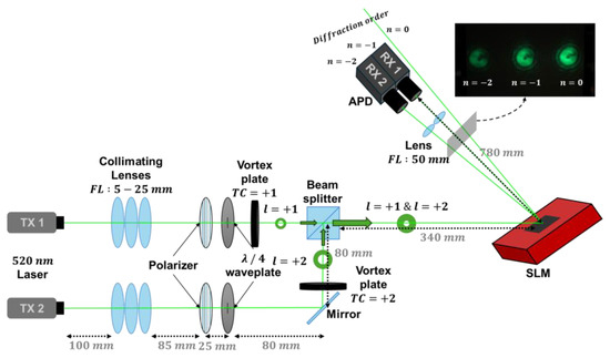
Figure 1.
Experimental setup.
The output beam from TX 1 passes through a vortex plate with a TC of + 1, thereby acquiring an OAM state of . Concurrently, the beam from TX 2 traverses a vortex plate with a TC of +, resulting in an OAM state of . The two OAM-modulated beams are subsequently combined spatially using a non-polarizing beam splitter, forming a multiplexed optical beam that carries both OAM components. This composite beam propagates through free space toward the receiver.
At the receiver side, an SLM configured with a fork grating pattern matching a selected TC is utilized to diffract the incoming OAM modes. The fork grating selectively reflects and diffracts each OAM mode into distinct spatial orders, with each diffraction order spatially separated based on its OAM index. Subsequently, the diffracted beams are focused by a lens system onto discrete avalanche photodiodes (APDs), positioned at the expected locations of specific diffraction orders. Each APD captures the optical intensity corresponding to a specific OAM mode and converts it into an electrical signal.
The electrical outputs from the APDs are subsequently fed into an oscilloscope, where the temporal waveforms are monitored. These signals are then digitized and processed using digital signal processing (DSP) techniques to recover the transmitted data. This setup effectively enables parallel data transmission over multiple OAM channels by assigning distinct topological charges to each channel. At the receiver, these channels are spatially demultiplexed based on their unique diffraction behavior through the SLM.
The SLM used in this study generates topological charge conversion (TCC). SLMs are highly programmable and versatile, enabling the dynamic generation and modification of arbitrary OAM modes in real-time by displaying a computer-generated hologram (CGH). This makes SLMs an ideal choice for experimental validation, rapid prototyping, and systems requiring mode reconfigurability. The detection of OAM beams holds equal significance and can frequently be accomplished by reversing the generation process by TCC. For instance, a fork grating generated by an SLM can be employed to convert an incoming OAM beam back into a fundamental Gaussian mode for detection purposes.
Figure 2 illustrates the holographic phase patterns loaded onto the SLM to generate fork gratings carrying TCs of + 1 and −1. These CGH patterns are synthesized by superimposing a vortex phase mask and a blazed grating, a sawtooth-shaped linear phase ramp that diffracts the incident Gaussian beam into a chosen diffraction order with high efficiency. The azimuthal phase profile of the vortex phase mask, , increases or decreases by 2π around the beam axis, imposing a helical phase structure that creates the beam with OAM. The resulting fork grating, depicted in the right-most figures, exhibits a characteristic dislocation at its center. This allows the grating lines to split to accommodate the phase singularity, directly encoding the topological charge into the first diffraction order. Inset enlargements highlight the divergence of groove spacing at this point. When illuminated by a Gaussian input, this composite hologram simultaneously performs mode conversion and spatial separation. It reconstructs only the matched OAM channel into a clean doughnut-shaped beam while suppressing other modes. This enables efficient demultiplexing in a multi-channel free-space optical communication scheme without additional beam-sorting optics.
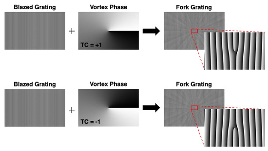
Figure 2.
Principle of generating fork grating CGH image on SLM.
Figure 3 shows theoretical and experimental OAM beam profiles. In Figure 3a, theoretical intensity distributions for LG modes (l = 0, +1, +2, +3) illustrate increasing spatial complexity with higher modes: l = 0 is Gaussian, l = +1 shows a central dark region (optical singularity) with a surrounding bright ring, and higher modes exhibit progressively larger singularities and rings. At l = +2, the central optical singularity and surrounding ring expand, and at l = +3, both features become more pronounced. This progression shows that as the mode order increases, the beam’s spatial structure becomes more complex, with a larger and more distinct central singularity and rings.
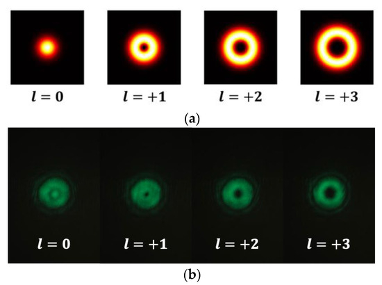
Figure 3.
(a) Theoretical and (b) experimentally measured LG mode (m = 0, l = 0, 1, 2, 3) of OAM beam.
Figure 3b depicts experimentally measured OAM lights with different LG modes, with disparities compared with Figure 1 due to various practical reasons, primarily due to imperfect phase modulation resulting from the finite resolution and misalignments within the optical setup. Furthermore, mode purity degradation and optical aberrations by an imperfect incident angle contribute to the observed ring distortions and speckle-like noise patterns. These deviations are inherent in physical implementations and are frequently unavoidable in practical OAM generation systems. Therefore, it is crucial to develop an efficient and effective mode discrimination scheme for free-space optical communication with a mode-division multiplexing scheme.
3. Proposed Method and Experimental Results
Figure 4 presents two distinct methods for selectively receiving multiplexed optical signals encoded with OAM modes using a spatially resolving receiver equipped with APDs. Each method facilitates discrimination between OAM channels by aligning the spatial distribution of the desired OAM beam with the active detection area of the APD, while rejecting undesired channels based on their spatial misalignment.
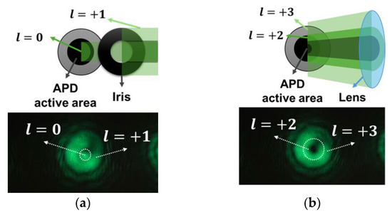
Figure 4.
Multiplexing scheme: (a) Using l = 0 beam for communication; (b) using l = 1 beam for communication.
In Figure 4a, the receiver is configured to detect a beam with , representing a Gaussian-like intensity profile with maximum intensity at the beam center. This configuration is achieved by setting the fork grating pattern displayed on the SLM with to demodulate incoming non-zero OAM modes, converting them to . Consequently, only the beam matched is reconstructed into a Gaussian shape, facilitating its efficient coupling into the active region of the APD, situated at the center of the optical axis. In contrast, a beam from another channel retains a ring-shaped intensity distribution due to its helical phase structure. This doughnut-shaped profile is supposed to result in a null at the beam center, possibly resulting in minimal overlap with the central active area of the APD. Thus, it significantly suppresses crosstalk from the undesired channel. The bottom image in Figure 4a depicts the corresponding captured intensity profile using a camera, where the Gaussian mode (centered at the first diffraction position) is discernible from the off-centered OAM modes.
Figure 4b illustrates the scenario where the receiver is configured to detect a beam converted by the SLM with , exhibiting a concentric ring-shaped intensity distribution with a central null. To optimize detection efficiency, the optical system preceding the APD incorporates a focusing lens, which precisely modifies the size and position of the beam, aligning the ring-shaped mode with precisely with the active region of the APD. This spatial alignment ensures that the doughnut-shaped intensity distribution is entirely contained within the sensitive region of the detector. Simultaneously, the other beam is converted to due to the elevated topological charge. Consequently, their intensity is predominantly distributed outside the active region of the APD, resulting in effective spatial filtering.
In both cases, it is shown that the strategy employed to spatially isolate a desired mode by matching it with the geometry of detector is one of the most important keys to successful mode-division multiplexing. In order to find the optimal strategy, it is crucial to observe the impact of imperfect OAM modes generated under practical system constraints by observing the converted beam shape after holograms with various vortex TCs on the SLM.
The beam shape images of experimentally implemented OAM modes are shown in Figure 5. The columns represent three distinct transmitter configurations: TX 1 with l = +1 activated, TX2 with l = +2 activated, and both TX 1 and TX 2 simultaneously activated to produce a composite OAM mode and showing overlapped images. The rows describe distinct TC values of the SLM, from on top to on the bottom. Each image is displaying distinct diffraction patterns corresponding to the diffraction orders of , , and . The row of the SLM with shows the initial state of OAM beams, where there is no vortex phase but only the blazed grating displayed on the SLM. Since no external TCs are added or subtracted, the TC of diffracted images are maintained constantly, showing a consistent size of optical singularity, the dark central region.
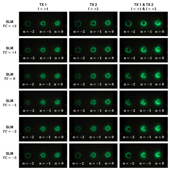
Figure 5.
Implementation of multi-channel LG-mode OAM utilizing vortex plates ( & ) and SLM with different TC values (n = diffraction order).
The intensity distributions observed in Figure 5 highlight key features of the OAM beams and their behavior when multiplexed. For , corresponding to a TC value of zero, the beam presents a Gaussian-like pattern with a prominent central spot. As the order of TC increases, as expected, the size of the central dark area expands and shows a symmetrical pattern based on the TC value. Despite the imperfectness, with possible spatial crosstalk due to the practical constraints discussed earlier, this pattern aligns with theoretical expectation and has been consistently observed across all TX configurations.
The row of the SLM with is the conventional scheme of detecting an beam. The beam from TX 1 with became the beam with on the position of diffraction order after reflecting from the SLM with . The beam from TX 2 with became the beam with on the position of diffraction order after reflecting from the SLM with . Both images show the central optical singularity is filled with light and the image of composite OAM beams when the SLM with shows the filled state is maintained when both beams are overlapped. Therefore, the demultiplexing process is able to achieve by extracting the center area with the radius that is equal to the optical singularity of an beam and discarding the outside area. However, even the subtle misalignment of individual beams causes interference between multi-channel beams, indicating the dark patterns on the outside of optical singularity in the right column. Due to the interference, conversion efficiency of generating an beam is decreased, and the delivered optical power to the receiver is deficient for reliable communication.
An alternative scheme proposed in this work for obtaining sufficient power and for discriminating the multiplexed modes to implement reliable MDM communication is to concentrate a concentric beam towards the active area of the APD. In this concentric intensity-based configuration, the SLM is set to display a fork grating with a TC value of +1. As depicted in the row of the SLM with in Figure 5, at the position of diffraction order , the beam from TX 1 transforms from to , while the beam from TX 2 transforms from to . A higher optical gain compared with the conventional scheme is achieved by concentrating the composite beam from the two individual channels utilizing a lens to fit into the active area of the APD. Analysis of the received intensity profiles in Figure 5 reveals that the proposed approach achieves nearly a two-fold improvement in discriminating adjacent modes compared with the conventional method.
Figure 6 illustrates the bit-error-rate (BER) performance and corresponding eye diagrams of an OAM-multiplexed FSO communication system, evaluated at the receiver position corresponding to the diffraction order (). This position is optimally aligned to detect the vortex beam emitted from TX 1, which carries a beam with , while ideally rejecting the signal from TX 2, characterized by a beam with , due to spatial and modal mismatch. However, practical limitations, such as imperfect spatial filtering and residual crosstalk, result in weak detection of the TX 2 signal, influencing the overall system performance. The experimental setup involves three distinct measurement scenarios: one with only TX 1 transmitting, another with only TX 2 transmitting, and a third where the separately measured signals from both transmitters are digitally combined post-measurement to simulate a multiplexed reception scenario. All signals are modulated using OOK, with the data rate on the x-axis expressed in Mbps and the BER on the y-axis plotted on a logarithmic scale. The figure comprises two subfigures: Figure 6a, which presents the results when the APD detects a beam, and Figure 6b, which shows the results when the APD is aligned to detect a beam with . Eye diagrams are included in each subfigure at the data rate where the BER of the combined signal is closest to the forward error correction (FEC) threshold of , providing a visual representation of signal integrity and noise characteristics.
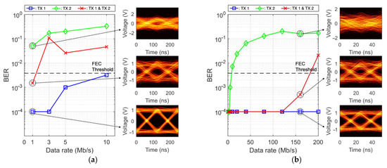
Figure 6.
BER graph of OAM multiplexing system: (a) SLM ; (b) SLM .
Figure 6a depicts the BER performance when the APD is configured to receive an OAM beam with , measured at data rates of 1, 3, 5, and 10 Mbps. Generating an beam using an SLM is inherently inefficient due to poor phase-flattening and mode conversion fidelity, resulting in a reduced optical gain at the receiver. This limitation significantly degrades the BER performance, even at relatively low data rates. The blue plot, representing the BER for TX 1 alone, exhibits a gradual increase with data rate, approaching below the FEC threshold at 10 Mbps. The green plot, corresponding to TX 2 alone, exhibits consistently high BER values across all data rates, reflecting the low coupling efficiency of the beam at the first diffraction position due to modal mismatch. The red plot, which represents the digitally combined signal from both channels, only satisfies the FEC threshold at 1 Mbps, where all higher data rates exceed the threshold. This indicates that inter-channel interference, combined with insufficient optical gain, severely restricts the ability of the system to support higher data rates in this configuration. The eye diagrams on the right side of Figure 6a, corresponding to the 10 Mbps data rate, further illustrate these trends. The eye diagram for TX 1 alone displays a relatively clear eye opening, indicating moderate signal integrity despite the reduced gain. In contrast, the eye diagram for TX 2 alone shows a heavily distorted waveform with a nearly closed eye, reflecting a low signal-to-noise ratio (SNR) due to the weak coupling of the beam. The eye diagram of the combined signal reveals a narrower eye opening compared with TX 1 alone, with increased noise and jitter, highlighting the detrimental impact of residual interference from TX 2.
Figure 6b presents the BER performance when the APD is aligned to detect an OAM beam with , matching the vortex beam profile of TX 1 after being reflected from the SLM with . The data rates tested were 1, 3, 5, 10, 20, 40, 80, 120, 160, and 200 Mbps. This configuration benefits from improved mode matching and optical alignment, resulting in higher coupling efficiency and optical gain, which significantly enhances the BER performance compared with the case in Figure 6a. The blue plot for TX 1 alone demonstrates near-error-free communication, with BER values approaching zero across the entire tested bandwidth, confirming the effectiveness of the alignment and mode-matching conditions. The green plot for TX 2 alone continues to show poor BER performance, as expected due to the spatial and modal mismatch at the same position; however, residual crosstalk is still evident.
The red plot, representing the combined signal from both channels, maintains a near-zero BER up to 120 Mbps, with a slight increase to approximately at 160 Mbps and a more pronounced degradation to 0.0210 at 200 Mbps, where it exceeds the FEC threshold. This degradation at higher data rates is primarily attributed to the bandwidth limitation of the arbitrary waveform generator (AWG) used in the experiment, which has a maximum bandwidth of 120 MHz, rather than an inherent limitation of the OAM multiplexing technique itself. The eye diagrams on the right side of Figure 6b, corresponding to the 200 Mbps data rate, provide further insight into the signal quality. The eye diagram for TX 1 alone exhibits a wide and well-defined eye opening, indicative of a high SNR and low jitter, reflecting excellent signal integrity under optimal conditions. The eye diagram for TX 2 alone is significantly degraded, with a nearly closed eye and substantial noise, consistent with the high BER values. The eye diagram of the combined signal shows a slightly narrower eye opening compared with TX 1 alone, with increased timing uncertainty and amplitude fluctuations due to interference from residual signal of TX 2, though the primary signal remains dominant.
The eye diagrams presented in both subfigures span approximately 250 ns on the time axis, with voltage scales calibrated to effectively visualize the waveform characteristics. These diagrams complement the BER measurements by providing a visual representation of the signal’s temporal and amplitude integrity, emphasizing the significance of precise mode filtering and spatial discrimination in OAM-multiplexed systems to effectively mitigate inter-channel interference. The concentric intensity-based configuration demonstrates the potential for high-data-rate communication with robust performance, while the conventional case highlights the challenges associated with inefficient mode conversion, which restricts achievable data rates and overall system reliability. The consistent poor performance of TX 2 at the position in both configurations underscores the efficacy of spatial mode separation in suppressing inter-channel interference, yet the residual impact of TX 2 in the combined signal scenarios underscores the necessity of enhanced receiver optics and spatial filtering strategies. These improvements could further minimize crosstalk and enhance channel isolation in future implementations. Collectively, the results presented in Figure 6 validate the feasibility of OAM multiplexing for FSO communication while identifying key areas for optimization, such as enhancing SLM efficiency and overcoming hardware bandwidth constraints, to fully realize its potential in practical high-data-rate applications.
4. Conclusions and Future Work
This study has proposed and experimentally validated a concentric intensity–based separation technique for adjacent OAM modes, thereby enhancing spatial selectivity and detection efficiency in a two-channel free-space optical multiplexing system. By mapping each topological charge to a distinct ring radius and aligning it with the active area of an APD, our approach addresses the efficiency and crosstalk limitations inherent in zero-order phase-flattening schemes. The concentric intensity–based method achieved an error-free performance beyond 100 Mbps, which is an order of magnitude improvement over the conventional configuration. Residual crosstalk from the other transmitter remained below the manageable level at practical data rates.
Increasing the transmission distance generally reduces the SNR of the system due to beam divergence, diffraction losses, and atmospheric turbulence, particularly for higher-order OAM modes with larger spatial extents. A reduced SNR degrades bit-error-rate performance, potentially lowering the maximum achievable data rate below the forward error correction threshold. To mitigate these effects, longer-range implementations may require higher optical launch power, aperture enlargement, advanced channel coding, or adaptive optics to dynamically correct wave-front distortions. Future experiments will quantitatively investigate the trade-off between distance and data rate in the proposed concentric intensity–based demultiplexing scheme.
In this study, OOK was used to ensure a fair comparison between the conventional detection scheme and the proposed method under identical conditions. Extending the system to higher-order modulation formats, such as multi-level PAM or OFDM, in order to further improve spectral efficiency will be investigated.
While this work demonstrates the effective separation of two adjacent OAM modes, scaling the technique to multiple channels (≥4 modes) is also possible, with some additional challenges in practice. Higher-order modes and the finite active area of the detector have an increasing risk of overlapping between adjacent channels. Potential solutions include using mode-sorting adaptive optics and incorporating multi-element APD arrays with optimized spacing.
Future research includes optimizing the optical gain through enhancing the diffraction efficiency of the SLM and generating high-resolution phase masks using a meta surface to significantly extend the achievable data rates. Additionally, integrating adaptive optics or machine-learning-based alignment control can dynamically mitigate misalignment and atmospheric turbulence in outdoor environments. Thirdly, scaling the technique to higher-order OAM channels and multi-channel configurations necessitates refined ring-radius calibration and receiver array architectures. Finally, combining concentric-ring demultiplexing with existing schemes such as coherent detection, polarization multiplexing, and wavelength division multiplexing promises to unlock terabit-scale throughput on compact FSO communication platforms. Collectively, these enhancements will bring OAM-multiplexed optical links closer to deployment in next-generation high-capacity FSO communication networks.
Author Contributions
Conceptualization, J.-Y.L. and H.C.; Methodology, J.-Y.L. and H.C.; Software, S.R.; Validation, J.K.; Formal analysis, J.-Y.L.; Investigation, J.-Y.L. and J.B.; Writing—original draft, J.-Y.L. and J.B.; Writing—review & editing, J.K., S.R., S.R.P. and H.C.; Visualization, J.-Y.L.; Supervision, S.R.P. and H.C.; Project administration, S.R.P. and H.C. All authors have read and agreed to the published version of the manuscript.
Funding
This research was supported by MSIT (the Ministry of Science and ICT), Korea, under the ITRC (Information Technology Research Center) support program (IITP-2025-RS-2023-00259061) supervised by IITP (the Institute for Information and Communications Technology Planning and Evaluation). Also, this work was supported by the Incheon National University Research Grant in 2022.
Data Availability Statement
The original contributions presented in this study are included in the article. Further inquiries can be directed to the corresponding authors.
Conflicts of Interest
The authors declare no conflict of interest.
References
- Ke, J.C.; Chen, X.; Tang, W.; Chen, M.Z.; Zhang, L.; Wang, L.; Dai, J.Y.; Yang, J.; Zhang, J.W.; Wu, L.; et al. Space-Frequency-Polarization-Division Multiplexed Wireless Communication System Using Anisotropic Space-Time-Coding Digital Metasurface. Nat. Sci. Rev. 2022, 9, nwac225. [Google Scholar] [CrossRef] [PubMed]
- Sasaki, H.; Yagi, Y.; Kudo, R.; Lee, D. 1.58 Tbps OAM Multiplexing Wireless Transmission With Wideband Butler Matrix for Sub-THz Band. IEEE J. Sel. Areas Commun. 2024, 42, 1613–1625. [Google Scholar] [CrossRef]
- Zhang, H.; Zhang, L.; Wang, S.; Lu, Z.; Yang, Z.; Liu, S. Tbit/s Multi-Dimensional Multiplexing THz-Over-Fiber for 6G Wireless Communication. J. Lightw. Technol. 2021, 39, 5783–5790. [Google Scholar] [CrossRef]
- Zhang, L.; Chen, M.Z.; Tang, W.; Dai, J.Y.; Miao, L.; Zhou, X.Y.; Jin, S.; Cheng, Q.; Cui, T.J. A Wireless Communication Scheme Based on Space- and Frequency-Division Multiplexing Using Digital Metasurfaces. Nat. Electron. 2021, 4, 218–227. [Google Scholar] [CrossRef]
- Mair, A.; Vaziri, A.; Weihs, G.; Zeilinger, A. Entanglement of the orbital angular momentum states of photons. Nature 2001, 412, 313–316. [Google Scholar] [CrossRef] [PubMed]
- Willner, A.E.; Ren, Y.; Xie, G.; Yan, Y.; Li, L.; Zhao, Z.; Wang, J.; Tur, M.; Molisch, A.F.; Ashrafi, S. Recent advances in high-capacity free-space optical and radio-frequency communications using orbital angular momentum multiplexing. Philos. Trans. R. Soc. A 2017, 375, 20150439. [Google Scholar] [CrossRef]
- Noor, S.K.; Zafar, A.; Ahmad, M.; Asif, R.; Yousaf, M.; Islam, S.U. A Review of Orbital Angular Momentum Vortex Waves for the Next Generation Wireless Communications. IEEE Access 2022, 10, 89465–89484. [Google Scholar] [CrossRef]
- Armghan, A.; Alsharari, M.; Aliqab, K.; Singh, M.; Aly, M.H.; El-Mottaleb, S.A.A. A 4 × 20 Gbps Inter-Satellite Optical Wireless Communication System Based on Orbital Angular Momentum Multiplexing: Performance Evaluation. Opt. Quant. Electron. 2024, 56, 1450. [Google Scholar] [CrossRef]
- Lee, D.; Sasaki, H.; Yagi, Y.; Shiba, H. Orbital Angular Momentum Multiplexing Using Radio Wave and Its Extension to Multishape Radio. J. Lightw. Technol. 2023, 41, 1985–1996. [Google Scholar] [CrossRef]
- Jing, H.; Cheng, W.; Li, Z.; Zhang, H. Concentric UCAs based low-order radio vortex wireless communications with co-mode interference. In Proceedings of the 2017 IEEE/CIC International Conference on Communications in China (ICCC), Qingdao, China, 22–24 October 2017; pp. 1–6. [Google Scholar]
- Xie, G.; Zhao, Z.; Yan, Y.; Li, L.; Ren, Y.; Ahmed, N.; Cao, Y.; Willner, A.J.; Bao, C.; Wang, Z.; et al. Demonstration of Tunable Steering and Multiplexing of Two 28 GHz Data Carrying Orbital Angular Momentum Beams Using Antenna Array. Sci. Rep. 2016, 6, 37078. [Google Scholar] [CrossRef]
- Lian, Y.; Yu, Y.; Han, S.; Luan, N.; Wang, Y.; Lu, Z. OAM Beams Generation Technology in Optical Fiber: A Review. IEEE Sens. J. 2022, 22, 3828–3843. [Google Scholar] [CrossRef]
- Firdous, F.; Kadlimatti, R. Generation Techniques of Orbital Angular Momentum Beams for Wireless Communication Applications. IEEE Access 2025, 13, 88174–88199. [Google Scholar] [CrossRef]
- Willner, A.E.; Song, H.; Zou, K.; Zhou, H.; Su, X. Orbital Angular Momentum Beams for High-Capacity Communications. J. Lightw. Technol. 2023, 41, 1918–1933. [Google Scholar] [CrossRef]
- Willner, A.E.; Zhao, Z.; Liu, C.; Zhang, R.; Song, H.; Pang, K.; Manukyan, K.; Song, H.; Su, X.; Xie, G.; et al. Perspectives on advances in high-capacity, free-space communications using multiplexing of orbital-angular-momentum beams. APL Photonics 2021, 6, 030901. [Google Scholar] [CrossRef]
- Li, L.; Zhang, R.; Zhao, Z.; Xie, G.; Liao, P.; Pang, K.; Song, H.; Liu, C.; Ren, Y.; Labroille, G.; et al. High-Capacity Free-Space Optical Communications Between a Ground Transmitter and a Ground Receiver via a UAV Using Multiplexing of Multiple Orbital-Angular-Momentum Beams. Sci. Rep. 2017, 7, 17427. [Google Scholar] [CrossRef]
- Mirhosseini, M.; Malik, M.; Shi, Z.; Boyd, R.W. Efficient Separation of the Orbital Angular Momentum Eigenstates of Light. Nat. Commun. 2013, 4, 2781. [Google Scholar] [CrossRef] [PubMed]
- Devlin, R.C.; Ambrosio, A.; Rubin, N.A.; Mueller, J.P.B.; Capasso, F. Arbitrary Spin-to-Orbital Angular Momentum Conversion of Light. Science 2017, 358, 896–901. [Google Scholar] [CrossRef] [PubMed]
- Pecoraro, A.; Cardano, F.; Marrucci, L.; Porzio, A. Continuous Variable Entanglement in Non-Zero Orbital Angular Momentum States. Proceedings 2019, 12, 7. [Google Scholar] [CrossRef]
- Lian, Y.; Qi, X.; Wang, Y.; Bai, Z.; Wang, Y.; Lu, Z. OAM Beam Generation in Space and Its Applications: A Review. Opt. Lasers Eng. 2022, 151, 106923. [Google Scholar] [CrossRef]
- Volke-Sepúlveda, K.; Garcés-Chávez, V.; Chávez-Cerda, S.; Arlt, J.; Dholakia, K. Orbital Angular Momentum of a High-Order Bessel Light Beam. J. Opt. B Quantum Semiclass. Opt. 2002, 4, S82. [Google Scholar] [CrossRef]
- Kotlyar, V.V.; Abramochkin, E.G.; Kovalev, A.A.; Savelyeva, A.A. Laguerre-Gaussian Beams with an Increased Dark Area and Autofocusing. Photonics 2022, 9, 708. [Google Scholar] [CrossRef]
- Wang, J.; Liu, J.; Li, S.; Zhao, Y.; Du, J.; Zhu, L. Orbital Angular Momentum and Beyond in Free-Space Optical Communications. Nanophotonics 2022, 11, 645–680. [Google Scholar] [CrossRef] [PubMed]
- Allen, L.; Beijersbergen, M.W.; Spreeuw, R.J.C.; Woerdman, J.P. Orbital angular momentum of light and the transformation of Laguerre-Gaussian laser modes. Phys. Rev. A 1992, 45, 8185–8189. [Google Scholar] [CrossRef] [PubMed]
- Su, M.; Liu, J.; He, Y.; Chen, S.; Li, Y. Optical Orbital Angular Momentum Demultiplexing and Channel Equalization by Using Equalizing Dammann Vortex Grating. Adv. Condens. Matter Phys. 2017, 2017, 6293910. [Google Scholar] [CrossRef]
- Zhu, L.; Deng, M.; Lu, B.; Guo, X.; Wang, A. Turbulence-resistant high-capacity free-space optical communications using OAM mode group multiplexing. Opt. Express 2023, 31, 14454–14463. [Google Scholar] [CrossRef]
- Shen, Y.; Wang, X.; Xie, Z.; Min, C.; Fu, X.; Liu, Q.; Gong, M.; Yuan, X.-C. Optical vortices 30 years on: OAM manipulation from topological charge to multiple singularities. Light Sci. Appl. 2019, 8, 90. [Google Scholar] [CrossRef]
- Zhang, Y.; Wen, S.; Wang, S.; Zhang, J.; Tang, C.; Zuo, H.; Gao, F.; Fan, F.; Zhang, Q.; Xu, Q. Fully Continuous Spiral Phase Plate for Ultraintense Optical Vortices. Opt. Lett. 2023, 48, 2760–2763. [Google Scholar] [CrossRef]
- Khonina, S.N.; Ustinov, A.V.; Logachev, V.I.; Porfirev, A.P. Properties of Vortex Light Fields Generated by Generalized Spiral Phase Plates. Phys. Rev. A 2020, 101, 043829. [Google Scholar] [CrossRef]
- Grigore, O.-V.; Craciun, A. Method for Exploring the Topological Charge and Shape of an Optical Vortex Generated by a Spiral Phase Plate. Opt. Laser Technol. 2021, 141, 107098. [Google Scholar] [CrossRef]
- Chen, S.; Cai, Y.; Li, G.; Zhang, S.; Cheah, K.W. Geometric metasurface fork gratings for vortex-beam generation and manipulation. Laser Photonics Rev. 2016, 10, 322–326. [Google Scholar] [CrossRef]
- Jiang, X.; Wang, A.; Yao, J.; Chen, R. Measuring High-Order Multiple Vortex Beams with Fork-Shaped Grating. Optik 2022, 257, 168742. [Google Scholar] [CrossRef]
- Lavery, M.P.J.; Peuntinger, C.; Günthner, K.; Banzer, P.; Elser, D.; Boyd, R.W.; Padgett, M.J.; Marquardt, C.; Leuchs, G. Free-Space Propagation of High-Dimensional Structured Optical Fields in an Urban Environment. Sci. Adv. 2017, 3, e1700552. [Google Scholar] [CrossRef] [PubMed]
Disclaimer/Publisher’s Note: The statements, opinions and data contained in all publications are solely those of the individual author(s) and contributor(s) and not of MDPI and/or the editor(s). MDPI and/or the editor(s) disclaim responsibility for any injury to people or property resulting from any ideas, methods, instructions or products referred to in the content. |
© 2025 by the authors. Licensee MDPI, Basel, Switzerland. This article is an open access article distributed under the terms and conditions of the Creative Commons Attribution (CC BY) license (https://creativecommons.org/licenses/by/4.0/).