Article

Hand Kinematic Model Construction Based on Tracking Landmarks

by
Yiyang Dong
and
Shahram Payandeh
*
Networked Robotics and Sensing Laboratory, School of Engineering Science, Simon Fraser University, Burnaby, BC V5A 1S6, Canada
*
Author to whom correspondence should be addressed.
Appl. Sci. 2025, 15(16), 8921; https://doi.org/10.3390/app15168921
Submission received: 23 June 2025 / Revised: 24 July 2025 / Accepted: 30 July 2025 / Published: 13 August 2025
(This article belongs to the Special Issue Human Activity Recognition (HAR) in Healthcare, 3rd Edition)

Abstract

Visual body-tracking techniques have seen widespread adoption in applications such as motion analysis, human–machine interaction, tele-robotics and extended reality (XR). These systems typically provide 2D landmark coordinates corresponding to key limb positions. However, to construct a meaningful 3D kinematic model for body joint reconstruction, a mapping must be established between these visual landmarks and the underlying joint parameters of individual body parts. This paper presents a method for constructing a 3D kinematic model of the human hand using calibrated 2D landmark-tracking data augmented with depth information. The proposed approach builds a hierarchical model in which the palm serves as the root coordinate frame, and finger landmarks are used to compute both forward and inverse kinematic solutions. Through step-by-step examples, we demonstrate how measured hand landmark coordinates are used to define the palm reference frame and solve for joint angles for each finger. These solutions are then used in a visualization framework to qualitatively assess the accuracy of the reconstructed hand motion. As a future work, the proposed model offers a foundation for model-based hand kinematic estimation and has utility in scenarios involving occlusion or missing data. In such cases, the hierarchical structure and kinematic solutions can be used as generative priors in an optimization framework to estimate unobserved landmark positions and joint configurations. The novelty of this work lies in its model-based approach using real sensor data, without relying on wearable devices or synthetic assumptions. Although current validation is qualitative, the framework provides a foundation for future robust estimation under occlusion or sensor noise. It may also serve as a generative prior for optimization-based methods and be quantitatively compared with joint measurements from wearable motion-capture systems.

1. Introduction

Within the past decades, hand tracking through various ambient sensing modalities has been gaining a considerable attention given its potential applications in many areas [1,2,3,4]. One of the immediate applications of such tracking and recognition is through the development of human–machine interaction, virtual reality, and tele-robotics. In addition, through increased precision in sensing modalities such as RGB-D sensing and through advances in deep-learning tracking models, it is now possible to establish a more accurate description of tracking hand landmarks defined through its various key anatomical locations. However, discerning the information regarding these spatial landmark data and constructing an accurate kinematic hand model faces several fundamental challenges. First, the human hand exhibits kinematic redundancy, with many degrees of freedom (DoF) leading to multiple possible configurations for the same fingertip position. Second, singularities may arise in certain joint configurations, complicating inverse kinematics. Third, anatomical variability across individuals can affect model generalizability. Our method addresses these by employing a hierarchical model structure that reduces redundancy through localized transformations, mitigating singularities through stable axis assignments, and leveraging real measurement data to accommodate anatomical differences. This approach enables practical estimation and reconstruction of realistic hand poses in diverse conditions.

1.1. Literature Review

1.1.1. Non-Invasive Hand-Tracking Systems

The sensing of hand and limb motion is a critical area of study with diverse applications, including human–computer interaction (HCI), virtual reality interfaces, and the monitoring of athletic performance. Existing commercial sensor systems often pose challenges due to their invasive nature, requiring users to wear specialized equipment, such as gloves or markers. This has created a need for alternative, non-invasive approaches.
One such effort is DigitEyes by Rehg et al. [5], a vision-based hand-tracking system that leverages a kinematic model to extract line and point features from grayscale images of unmarked hands. It enables real-time tracking for applications like 3D mouse interaction. Further advancing grayscale-based tracking, Rehg et al. [6] introduced a method capable of recovering the state of a 27-degrees-of-freedom (DoF) hand model using only standard grayscale video input. These early studies highlight the complexity of accurately modeling highly articulated mechanisms such as the human hand, which involve a vast state space and intricate visual patterns.

1.1.2. Depth-Based and Anatomically Constrained Models

The introduction of depth sensors has significantly improved the robustness and precision of 3D hand pose estimation. However, a persistent challenge is ensuring that predictions comply with anatomical constraints. Addressing this, Isailovic et al. [7] proposed an anatomical filter that accepts 3D tracker outputs and corrects the resulting 26-DoF hand vectors using biomechanical limitations, thereby enhancing realism.
Alternative sensing modalities have also been explored. For example, Li et al. [8] presented Aili, a table-lamp system that reconstructs hand skeletons without cameras or wearables. Using LED panels and low-cost photodiodes, it derives 2D binary blockage maps to infer hand position and shape, demonstrating a seamless blend of sensing and everyday utility.
Other studies focus on marker-based validation. Cereatti et al. [9] developed a multi-camera system with 24 surface markers to reconstruct finger kinematics in real time. Their method relies on a rigid-body model with 22 DoFs and includes automatic calibration for joint axes and rotation centers. This system has been validated on thumb flexion, grasping, and pointing tasks.

1.1.3. Kinematic Modeling from Anatomical Landmarks

The importance of anatomical accuracy extends beyond human motion. For instance, Haufe et al. [10] introduced a detailed kinematic model of Drosophila legs using anatomical landmarks such as condyles, which better capture the natural orientation of oblique joint axes. In the context of human-hand tracking, Ji and Yang [11] proposed a hierarchical topology-based method. Their approach defines global palm orientation and local finger-joint connectivity, then uses angle-based features with a regression forest to estimate 3D joint positions.
Pena et al. [12] contributed a simulation framework for manipulation and grasping based on a 25-DoF skeletal hand model. Their model incorporates palm arching and additional wrist/carpometacarpal joint DoFs, enhancing anatomical fidelity. They define joint relationships using Denavit–Hartenberg parameters, allowing for workspace estimation and detailed motion simulation.

1.1.4. Recent Advances in Adaptive and Probabilistic Modeling

Recent research emphasizes anatomical constraints, adaptiveness, and probabilistic modeling in hand kinematics. Zimmermann and Brox [13] introduced a hybrid learning model integrating biomechanical priors for real-time 3D pose estimation. Lapresa, Zollo and Cordella [14] developed a subject-specific adaptation framework that updates kinematic parameters online. Xu and Lee [15] formulated a probabilistic estimation approach that accounts for occlusions and enforces anatomical plausibility via joint limit constraints. These works illustrate a growing shift toward anatomically informed, subject-adaptive models—principles that also motivate the framework proposed in this paper.

1.1.5. MediaPipe-Based Tracking and Limitations

MediaPipe-based solutions have gained traction due to their efficiency and wide deployment. Amprimo et al. [2] validated both the standard Google MediaPipe Hand (GMH) model and a depth-enhanced variant (GMH-D), showing improved spatial accuracy in clinical hand assessments when compared against motion-capture ground truth. Similarly, Pfisterer et al. [16] demonstrated that fusing MediaPipe landmarks with RGB-D data from RealSense sensors could improve gesture recognition in human–robot interaction scenarios.
While these systems effectively enhance landmark accuracy through depth integration, they largely treat the tracked keypoints as direct pose inputs without explicitly modeling the underlying kinematics. In contrast, our approach introduces a fully articulated hierarchical kinematic model. We define local coordinate frames for each joint, solve both forward and inverse kinematics based on spatial geometry, and reconstruct hand postures using Unity3D (version 2023.2.20f1) for visual validation. This framework offers high interpretability, facilitates simulation, and supports future extensions under noisy or incomplete observations.

2. Background Material

2.1. Sensor Specifications

To ensure accurate 3D measurements of hand landmarks, we employed the Intel RealSense D435i RGB-D camera (Intel Corporation, Santa Clara, CA, USA) as our sensing device. The D435i integrates a high-resolution RGB sensor (1920 × 1080 at 30 frames per s) with an active infrared stereo depth sensor (1280 × 720 at 30 frames per s). The depth sensing operates within a range of 0.2 to 10 m, with a stereo baseline of 50 mm and field of view of approximately 87 × 58 . The sensor provides synchronized RGB and depth frames, enabling frame-by-frame fusion of 2D image coordinates and calibrated depth values. In our experimental setup, the RealSense SDK v2.56.1 was used to extract aligned RGB and depth frames. All depth measurements were calibrated in millimeters and subsequently converted into 3D spatial coordinates using the camera’s intrinsic parameters, as detailed in Appendix A.

2.2. MediaPipe

MediaPipe Hand [17] (Google AI Edge Portal) is a hand-tracking framework that provides a solution for detecting and estimating the 2D hand landmarks in video streams using a single RGB camera. The MediaPipe Hand model tracks 21 distinct hand landmarks, which is achieved through a pipeline that integrates hand detection, keypoint localization, and pose estimation. The pixel coordinates in the RGB image for each hand landmark can be expressed as a pair of values or in vector form:
p i = ( u i , v i ) = u i v i , for i = 0 , , 20 ,
here, u i and v i represent the pixel coordinates of the ith landmark with respect to the image buffer frame. These landmark coordinates can then be calibrated in order to associate the representative pixel coordinates to the physical coordinate with respect to the sensor frame.
In order to associate additional coordinate measure to the existing 2D measurement, MediaPipe also offers an estimate of the physical distance of the landmarks with respect to the sensor frame. For example, Figure 1 illustrates three distinct tracking frames of a continuous hand movement sequence between calibrated the near to far distances with respect to the sensor.
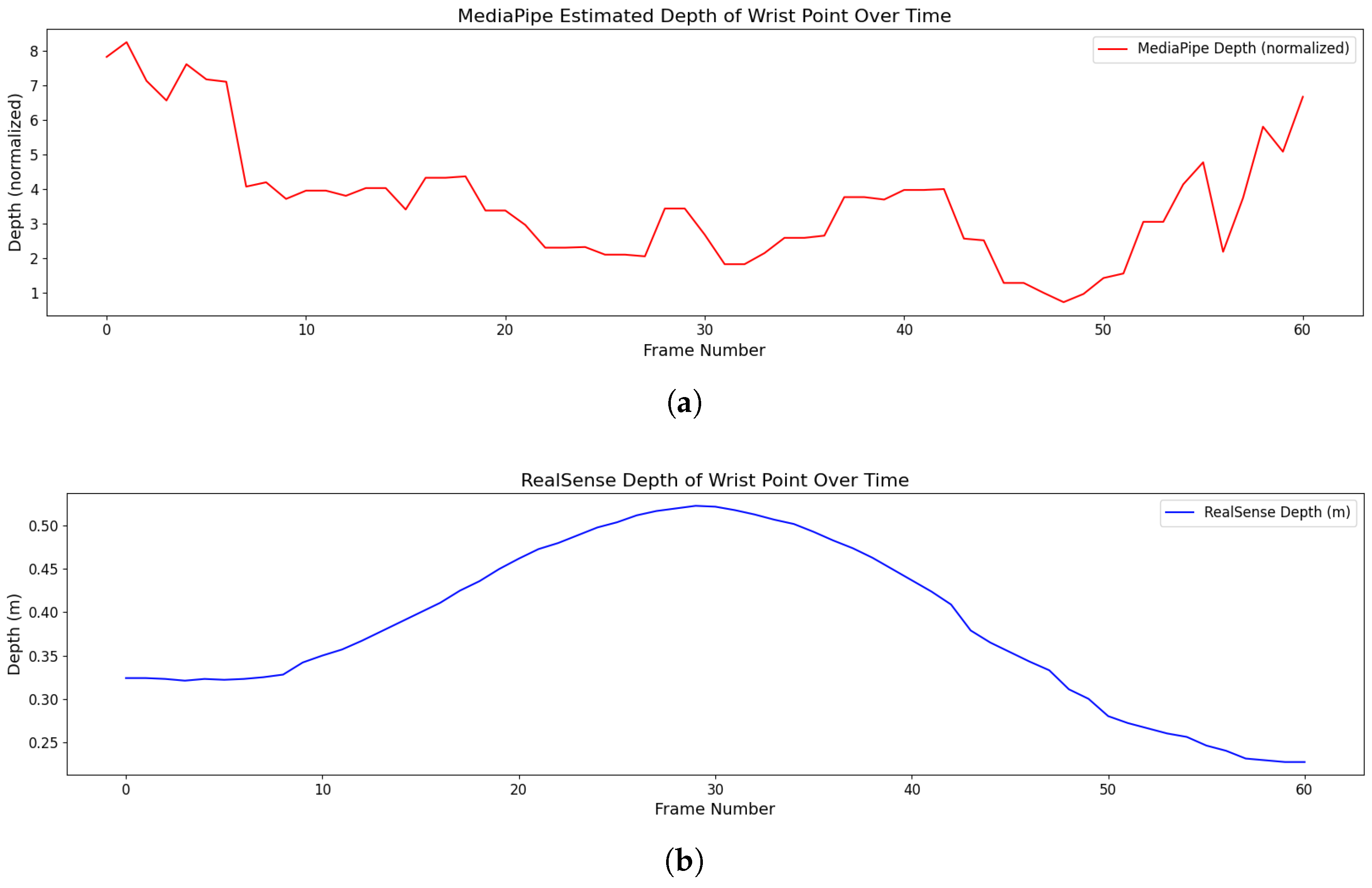
As can be seen in Figure 2a, the estimated depth values of the tracked landmarks provided by MediaPipe algorithm are not consistent. To remedy this inconsistency, we have utilized an RGB-D sensor which can offer a calibrated depth or distance of the measured landmarks with respect to the sensor frame. Comparing the results of Figure 2b with Figure 2a, the advantages of utilizing an additional sensing modality which can be fused with the information obtained from the MediaPipe tracking algorithm can be observed (See Appendix A). In addition, since MediaPipe’s depth estimation is not calibrated to real-world physical units, this renders it ineffective for fulfilling the objectives of this paper.
This integration replaces the relative depth estimates from the MediaPipe Hand model with the actual depth values obtained from the Intel RealSense RGB-Depth sensor (Intel Corporation, Santa Clara, CA, USA). The 2D pixel coordinates ( u i , v i ) , initially estimated by MediaPipe, along with their corresponding depth values d ( u i , v i ) captured by the depth sensor, are converted into real-world 3D spatial coordinates using the camera’s intrinsic parameters—specifically, the focal lengths f x , f y , and the principal point offsets c x , c y (see Appendix A for further details on aligning the RGB image pixels with the depth buffer). Notably, ( u i , v i ) in the RGB and depth buffers may differ and require calibration). This transformation enables the calculation of the accurate real-world 3D spatial coordinates d i = ( x i , y i , z i ) and the ith hand landmark, with respect to the sensor. The conversion can be expressed mathematically as:
x i = ( u i c x ) · d ( u i , v i ) f x y i = ( v i c y ) · d ( u i , v i ) f y z i = d ( u i , v i ) , i = 0 , , 20
In the next section, we present a method on how to construct the kinematic model of the hand using the spatial information of these tracked landmarks. The overall kinematic model comprises the local root coordinate frame associated with the palm describing the position and transformation of the hand with respect to the world coordinate frame, i.e., the sensor coordinate, and a collection of coordinate frames and an associated transformation matrix describing the kinematic model of the finger with respect to the palm-coordinate frame.

3. Hand Kinematic Model Definitions

In this section, we present an approach for constructing the kinematic model of the hand based on the spatial landmarks’ tracking information. We first define the kinematic world coordinate frame, according to which all the coordinates of the hand landmarks are measured. The definition of the origin of the local hand coordinate frame based on the landmark definitions of MediaPipe is presented in Section 3.2, followed by definitions of hand kinematic parameters presented in Section 3.3.

3.1. The World-Frame Definition

When we are defining a model for a moving hand within a three-dimensional space, two primary parameters are necessary for describing the state of the hand at any given time, namely position and orientation. The description of these parameters is inherently relative, as both the position and orientation of an object such as the whole hand is always referenced with respect to the origin and three pre-defined orthogonal axes of a fixed universal (world) coordinate frame, also referred to as the global frame.
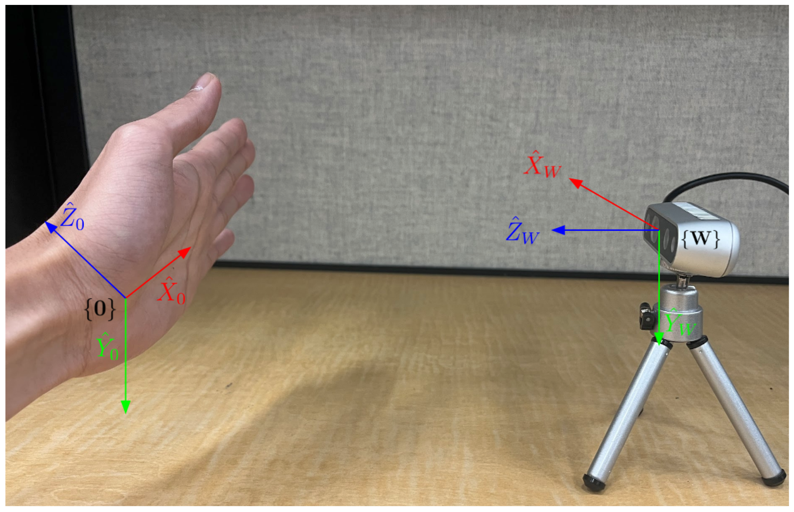
By convention, the world frame, denoted by { W } , is usually attached to a non-moving object, thereby enabling all hand movements to be described with respect to it. In this paper, the sensor frame, located at the center of the sensor, is adopted as the world frame, as is shown in Figure 3.
We denote the unit vectors representing the three principal directions of the world frame { W } as X ^ w , Y ^ w and Z ^ w . To align with the 2D image-frame systems, where pixel coordinates originate from the upper-left corner, axes X ^ w and Y ^ w are oriented to the right and downwards, respectively. This alignment simplifies the process of mapping 2D image pixels to 3D real-world coordinates using physically calibrated measurable quantities (see Appendix A). Finally, using the right-hand rule, we establish that the Z ^ w axis points from the sensor toward the objects, which aligns with the depth data measurement, representing the distance between the hand and the sensor.

3.2. Definitions of Hand Hierarchical Coordinate Frames

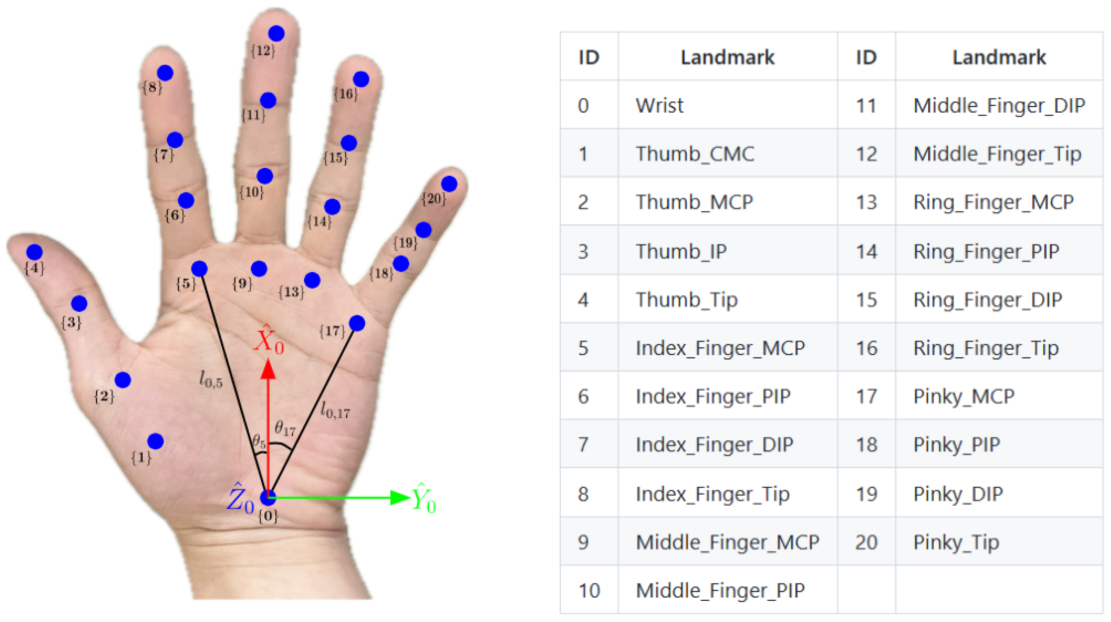
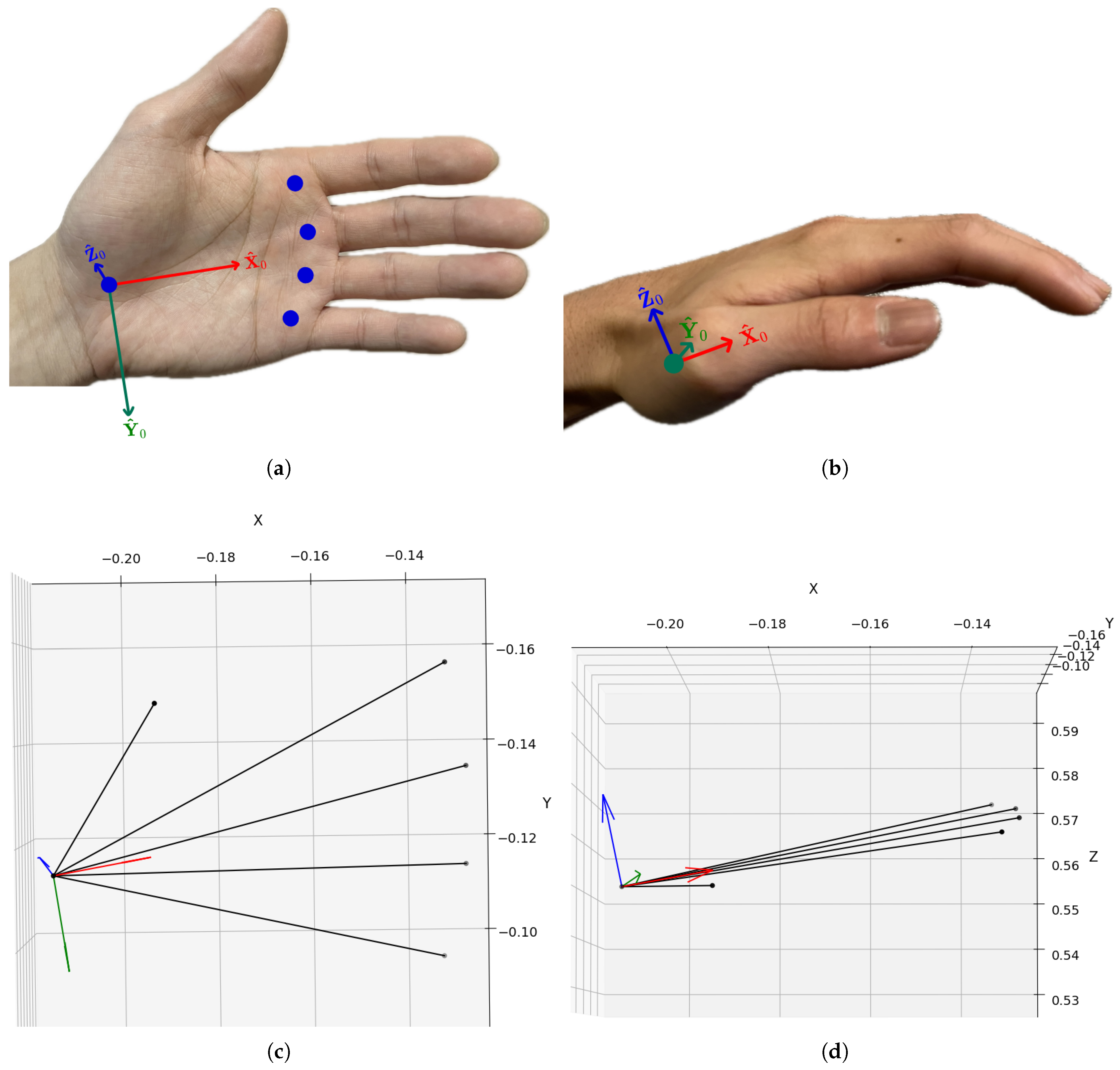
In the world coordinate frame { W } , the hand’s position can be located, and further the rotational joint angle of each finger joint can be described by defining local (or relative) coordinate frames. The wrist frame { 0 } , which is affixed to the wrist of the hand with origin defined at the wrist landmark is define relative to the world frame. While the definition of this relative coordinate frame is arbitrary, as shown in Figure 4, we define the Y ^ 0 of the wrist frame to be aligned with the general direction of finger flexion; the unit vector X ^ 0 is oriented from the wrist towards the root of the middle finger, while Z ^ 0 is orthogonal to the palm plane defined by the other axes, resulting in a direction that points towards the back of the hand by assuming that the front of the hand faces the sensor.
The kinematic model of the hand is based on 21 landmarks, including 1 root (the wrist) and 20 links (phalanges) across the five fingers. Each link is assigned a corresponding local frame, allowing for a description of the position and rotation of each link.
This model employs a hierarchical structure of local frames corresponding to anatomical joints. As shown in Figure 4, the first layer includes local frames { 1 } , { 5 } , { 9 } , { 13 } , and { 17 } at the metacarpophalangeal (MCP) joints, defined with respect to the root frame { 0 } . The second layer consists of local frames { 2 } , { 6 } , { 10 } , { 14 } , and { 18 } at the proximal interphalangeal (PIP) joints, defined relative to the first layer. Similarly, frames { 3 } , { 7 } , { 11 } , { 15 } , and { 19 } at the distal interphalangeal (DIP) joints form the third layer. Finally, the fourth layer comprises frames { 4 } , { 8 } , { 12 } , { 16 } , and { 20 } at the fingertips.
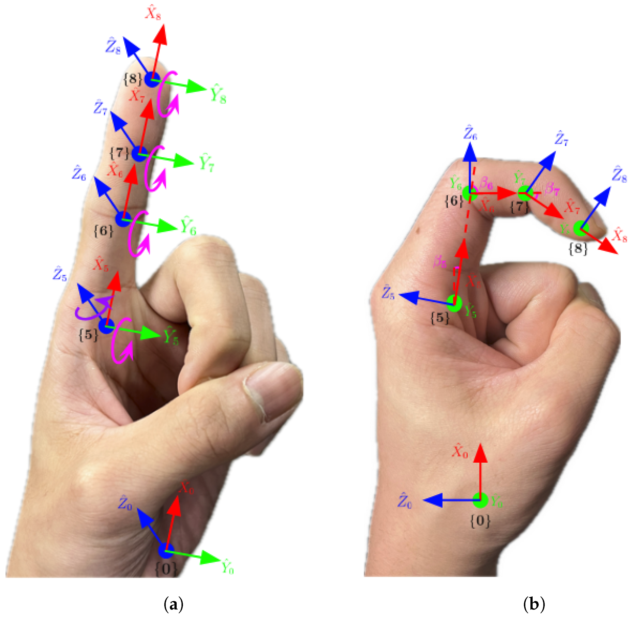
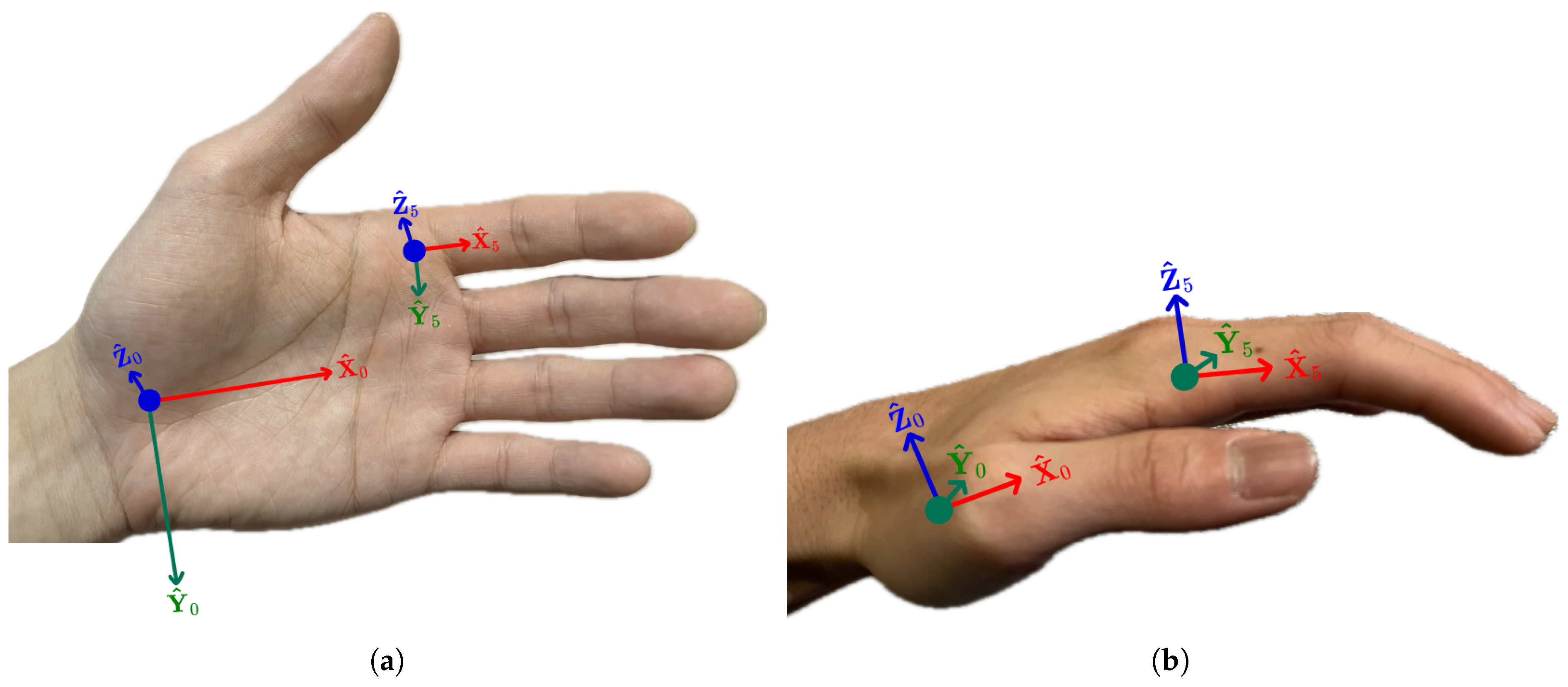
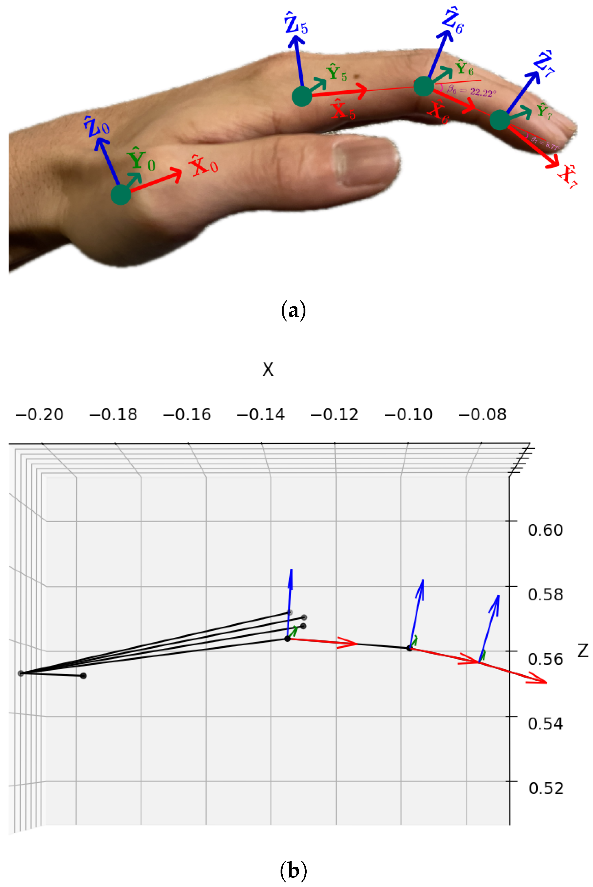
Each metacarpophalangeal (MCP) joint, or finger root, possesses two degrees of freedom (DOF), enabling it to flex and extend (bend up and down) as well as abduct and adduct (move side to side). When the root of a finger is fixed, and the finger is bent up and down, the proximal interphalangeal (PIP) and distal interphalangeal (DIP) joints each exhibit one DOF. Consequently, the workspace (the area the fingertip can reach) of a finger is a two-dimensional plane. Each of the five fingers can thus be modeled as a kinematic chain comprising three links connected by three revolute joints, with parallel rotation axes. The axes Y ^ of the local frames for each finger align with the axes of the revolute joints, pointing to the page, as illustrated in Figure 5. The axes X ^ for each of the three joints orient towards the origin of the subsequent frame. For example, along the index finger, X ^ 5 points to the origin of local frame { 6 } , X ^ 6 to the origin of local frame { 7 } , and X ^ 7 to the origin of local frame { 8 } . Note that since { 8 } is located at fingertip and has no DOF, X ^ 8 aligns with X ^ 7 . The axes Z ^ of the local frames are assigned using the right-hand rule. This layered approach effectively models the intricate kinematic structure of the human hand. Although the present approach primarily includes grasping and natural resting poses, the model is capable of representing a wider range of joint configurations.

3.3. Hand Kinematic Parameters

Kinematic modeling involves a mathematical framework to represent the motion properties of a system such as a robot or a human hand, without considering the forces that cause the movements. It provides a way to describe, for example, the positions and orientations of the interconnected segments or links within the structure relative to each other and fixed world frame. This model is essential, for example, in understanding and predicting how joint movements translate into overall hand movement.
In this context, forward kinematics refers to the process of calculating the positions and orientations of the fingertips and intermediate links of the hand relative to the wrist and the world frame, given known joint angles and the fixed kinematic parameters of the hand. This computation starts from the base frame (e.g., the wrist) and propagates outward through the hand kinematic chain. On the other hand, inverse kinematics focuses on determining the joint angles needed to achieve a specific kinematic configuration of the hand.
In this subsection, we define the parameters of the kinematic model for the palm and fingers. The next section presents methods to resolve these kinematic model parameters for the hand using data collected from the MediaPipe Hand model and the RGB-D sensor.
Palm Parameters:In this paper, we represent the model of the palm as a planar structure in three-dimensional space. We assume that the wrist and the roots of the five fingers lie on a single plane, specifically the xy-plane of the local frame { 0 } . A set of 16 parameters are defined, where the initial six parameters are time-varying while the five length and five angle parameters are assumed to be constant:
  • Position Parameters: The position vector d 0 w = ( x 0 , y 0 , z 0 ) T specifies the distance of translation between the origins of the wrist frame { 0 } and the world frame { W } along X ^ w , Y ^ w and Z ^ w , respectively.
  • Orientation Parameters: The orientation of the local frame { 0 } is defined by the Euler angles { γ 0 , β 0 , α 0 } ; these angles describe the sequential rotations around axes Z ^ 0 , Y ^ 0 , and X ^ 0 .
  • Base Length Parameters: The lengths { l 0 , 1 , l 0 , 5 , l 0 , 9 , l 0 , 13 , l 0 , 17 } represent the fixed distances between the origin of the local frame { 0 } and the origins of local frames { 1 } , { 5 } , { 9 } , { 13 } , and { 17 } . These measurements, in centimeters, are spatial relationships between the wrist and finger roots.
  • Angle Parameters: The angles { θ 1 , θ 5 , θ 9 , θ 13 , θ 17 } describe the rotational offset between the X ^ 0 axis and the axes X ^ 1 , X ^ 5 , X ^ 9 , X ^ 13 , and X ^ 17 , respectively. These angles, measured in radians, are pivotal for capturing the hand’s natural articulation around the Z ^ 0 axis.
Parameters of Fingers: As shown in Figure 5, each finger requires three length parameters (as constraints) and four angle parameters (between 0 to 90 degrees) to define its pose, amounting to a total of 35 parameters for all five fingers:
  • Base-Length Parameters: A set of 15 parameters determines the fixed lengths of the three links l i , i + 1 , l i + 1 , i + 2 and l i + 2 , i + 3 , within each finger, where i = 1 , 5 , 9 , 13 , 17 :
    { ( l 1 , 2 , l 2 , 3 , l 3 , 4 ) , ( l 5 , 6 , l 6 , 7 , l 7 , 8 ) , ( l 9 , 10 , l 10 , 11 , l 11 , 12 ) , ( l 13 , 14 , l 14 , 15 , l 15 , 16 ) , ( l 17 , 18 , l 18 , 19 , l 19 , 20 ) }
  • Angle Parameters for Finger Roots: A set of 10 parameters describes five pairs of rotation angles β i and γ i around axes Y ^ i and Z ^ i for the root joints of each finger, where i = 1 , 5 , 9 , 13 , 17 :
    { ( β 1 , γ 1 ) , ( β 5 , γ 5 ) , ( β 9 , γ 9 ) , ( β 13 , γ 13 ) , ( β 17 , γ 17 ) }
  • Angle Parameters for Other Joints: A set of 10 parameters describes five pairs of rotation angles β i + 1 and β i + 2 for the PIP and DIP joints around corresponding Y ^ i of each finger, i = 1 , 5 , 9 , 13 , 17 :
    { ( β 2 , β 3 ) , ( β 6 , β 7 ) , ( β 10 , β 11 ) , ( β 14 , β 15 ) , ( β 19 , β 20 ) }

4. Hand Hierarchical Transformations

To effectively track human-hand movements and reconstruct its corresponding kinematic representation for graphical reconstruction, it is essential to represent the position and orientation of each joint’s local coordinate frame in 3D space and the corresponding joint parameters of each finger. We introduce a systematic approach for resolving these parameters through transformations between adjacent coordinate frames. The input parameters are spatial coordinates of 21 hand landmarks provided by the MediaPipe through RGB-D sensor, which are position parameters of each origin of the local frame { i } with respect to world frame { W } , denoted as vector d i w = ( x i , y i , z i ) T for i = 0 , 1 , , 20 , (Section 3.1). Table 1 shows the representation of these measured 3D spatial coordinates for each joint of the thumb, index, middle, ring, and little fingers.
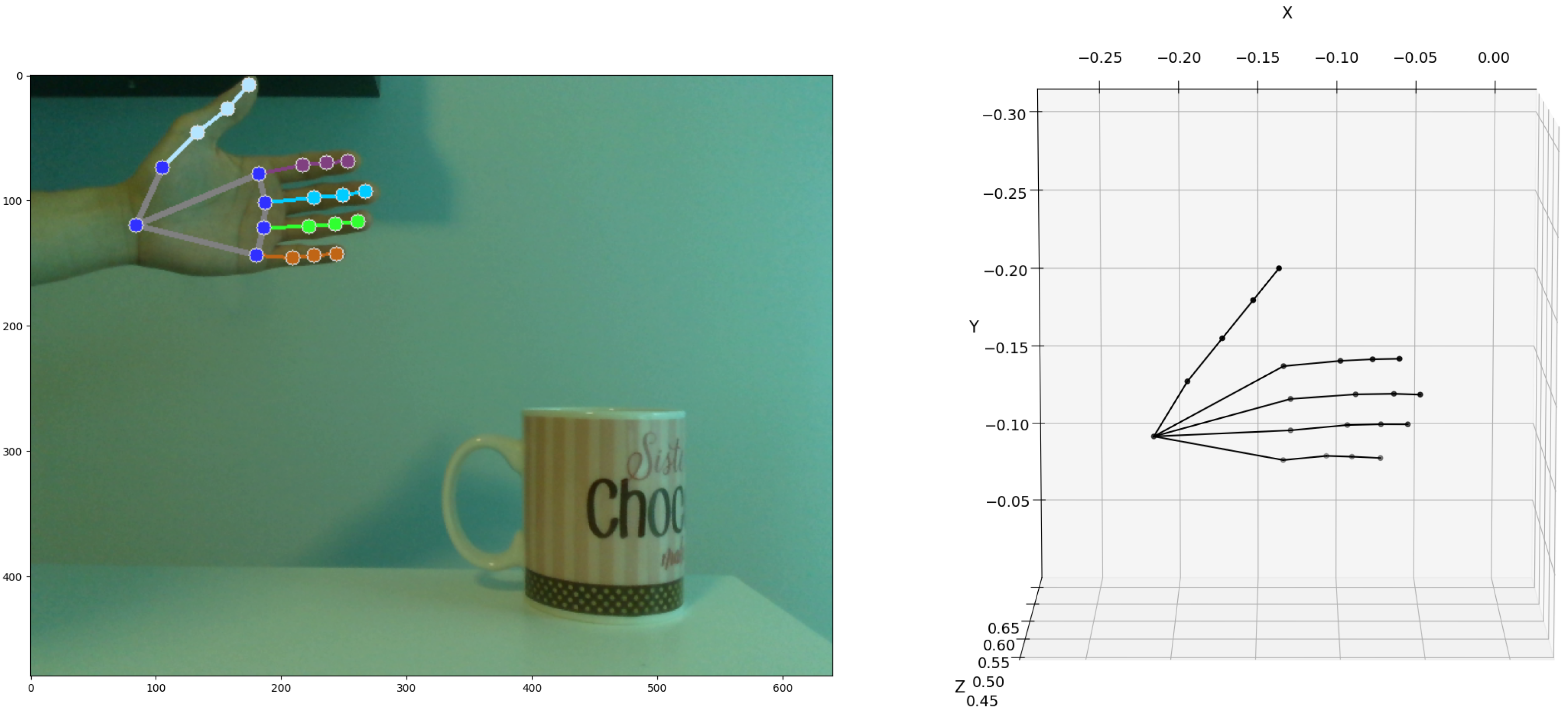
Figure 6 shows the 2D hand-tracking data and the corresponding raw 3D calibrated measured data reconstruction. On the left, the RGB image shows a hand in a front-facing position, where key hand landmarks are tracked using the MediaPipe framework. These landmarks are accurately projected onto the image plane, ensuring comprehensive coverage of all joint locations. On the right, we visualize the 3D point cloud of these landmarks using depth data from an RGB-D sensor. The depth values associated with each landmark are mapped to their respective x and y coordinates derived from the MediaPipe are mapped to the depth buffer (Appendix A).
Table 2 provides the 3D hand landmark data d i w in meters relative to the world frame, where the origin is aligned with the RGB-D sensor. The positive x-axis extends to the right, the positive y-axis points downward, and the z-axis represents the depth from the sensor.
It is important to note that the fixed-length parameters used in this study are derived from the physical measurements of a single individual. While this enables precise modeling for a given user, the approach does not capture variability in hand sizes or joint constraints across the population. As such, unrealistic joint configurations may arise if this model is applied directly to users with different hand geometries. Future work will explore methods to generalize the model by incorporating user-specific calibration procedures or employing learning-based techniques to estimate anatomical parameters from motion data.
In the following section, we present a numerical example illustrating the process of resolving parameters for hierarchical transformations in the index finger after each transformation definition.

4.1. Resolution of Palm-Coordinate Frame

In this subsection, we present the method for computing the palm’s orientation and position which is used as the hand local coordinate system at { 0 } .
Position Parameters:The position vector d 0 w = ( x 0 , y 0 , z 0 ) T , directly measured from Mediapipe and the RGB-D sensor, specifies the distance of translation between the origins of the wrist frame { 0 } and the world frame { W } along X ^ w , Y ^ w , and Z ^ w , respectively. For example, the position vector:
d 0 w = ( 0.2113 , 0.1128 , 0.5380 )
indicates that the wrist landmark is located 0.21 m to the left, 0.11 m above the sensor, and 0.54 m away from the sensor, as measured by the MediaPipe through calibrated RGB-D measures.
Orientation Parameters: In the kinematic model of the hand, the orientation of the palm is with respect to the world frame is parameterized by three degrees of freedom (DOF). Let R x ( α 0 ) , R y ( β 0 ) , and R z ( γ 0 ) represent rotations about axes X ^ 0 , Y ^ 0 , and Z ^ 0 , respectively, where α 0 , β 0 , and γ 0 denote the corresponding rotation angles. Given the set of Euler angles { α 0 , β 0 , γ 0 } , the orientation matrix of the wrist frame { 0 } can be computed by converting the Euler angles to a rotation matrix:
R 0 w = R z ( γ 0 ) R y ( β 0 ) R x ( α 0 ) = cos γ 0 sin γ 0 0 sin γ 0 cos γ 0 0 0 0 1 cos β 0 0 sin β 0 0 1 0 sin β 0 0 cos β 0 1 0 0 0 cos α 0 sin α 0 0 sin α 0 cos α 0 = cos γ 0 cos β 0 cos γ 0 sin β 0 sin α 0 sin γ 0 cos α 0 cos γ 0 sin β 0 cos α 0 + sin γ 0 sin α 0 sin γ 0 cos β 0 sin γ 0 sin β 0 sin α 0 + cos γ 0 cos α 0 sin γ 0 sin β 0 sin α 0 cos γ 0 sin α 0 sin β 0 cos β 0 sin α 0 cos β 0 cos α 0 = X ^ 0 w Y ^ 0 w Z ^ 0 w
where each column of R 0 w denotes the principal directions of the wrist frame { 0 } in terms of the world frame { W } . This matrix encapsulates the wrist’s orientation in the global coordinate system.
To resolve the palm’s orientation parameters, we first define the Y ^ 0 of the wrist frame { 0 } as the normalized vector between landmark 5 (base of the index finger) and landmark 13 (base of the ring finger). These two landmarks provide a consistent reference indicator for of the construction of the palm’s orientation matrix, or:
Y ^ 0 w = d 13 w d 5 w d 13 w d 5 w .
Next, we define the Z ^ 0 as the normal vector to the above defined palm plane. We define this vector through selection of two vectors: one from landmark 0 (wrist) to landmark 9 (base of the middle finger) and Y ^ 0 as:
Z ^ 0 w = d 9 w d 0 w d 9 w d 0 w × Y ^ 0 w .
Finally, the unit vector X ^ 0 is determined using the right-hand rule, ensuring a consistent and orthogonal coordinate construction:
X ^ 0 w = Y ^ 0 w × Z ^ 0 w ,
Given the description of R 0 w in terms of the palm landmarks, the parametrization of the hand orientation with respect to the world frame can be described using three Euler angles ( α 0 , β 0 , γ 0 ) , which can be obtained through inverse calculation as:
β 0 = arcsin ( X ^ 0 , z w ) γ 0 = arctan ( X ^ 0 , y w , X ^ 0 , x w ) α 0 = arctan ( Y ^ 0 , z w , Z ^ 0 , z w )
Given the position vector of the hand wrist as d 0 w = ( x 0 , y 0 , z 0 ) T , the position and orientation of frame are determined. We represent the final pose matrix of the palm using a homogeneous transformation matrix:
T 0 w = R 0 w d 0 w 0 1 × 3 1
Follow Equations (5)–(7), the principal unit axes of the wrist frame { 0 } can be determined as:
Y ^ 0 w = d 13 w d 5 w d 13 w d 5 w = ( 0.0017 , 0.0380 , 0.0090 ) ( 0.0017 , 0.0380 , 0.0090 ) = ( 0.0427 , 0.9720 , 0.2310 ) Z ^ 0 w = d 9 w d 0 w d 9 w d 0 w × Y ^ 0 w . = ( 0.0837 , 0.0235 , 0.0320 ) ( 0.0837 , 0.0235 , 0.0320 ) × ( 0.0427 , 0.9720 , 0.2310 ) = ( 0.3963 , 0.1957 , 0.8970 ) X ^ 0 w = Y ^ 0 w × Z ^ 0 w = ( 0.0427 , 0.9720 , 0.2310 ) × ( 0.3963 , 0.1957 , 0.8970 ) = ( 0.9171 , 0.1299 , 0.3768 )
Given the above resolved palm-coordinate frame from the landmark data, we can construct the homogeneous transformation matrix T 0 w of the palm-coordinate frame located at landmark 0 with respect to the world frame as:
T 0 w = 0.9171 0.0427 0.3963 0.2113 0.1299 0.9720 0.1957 0.1128 0.3768 0.2310 0.8970 0.5380 0 0 0 1
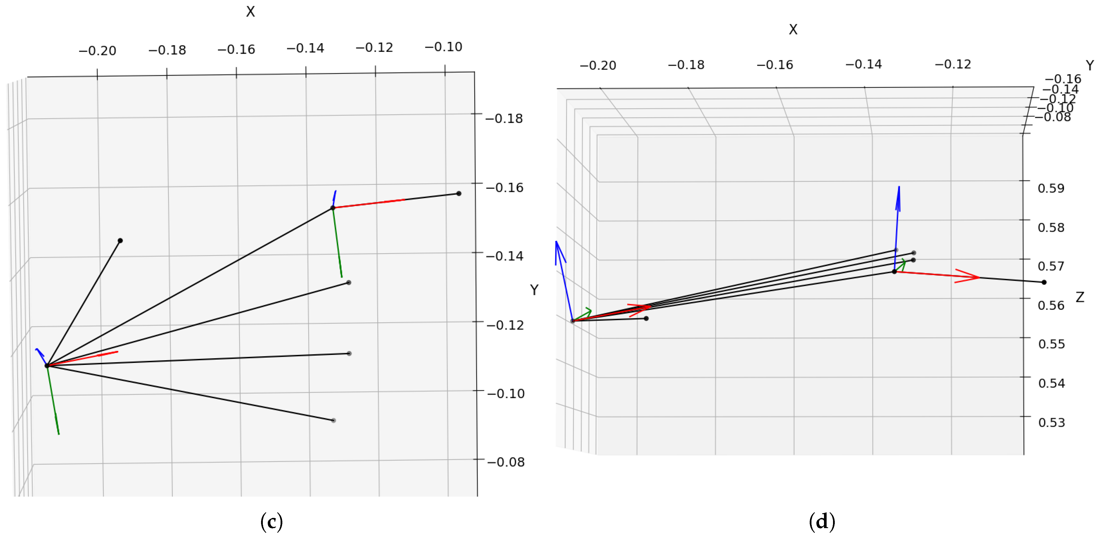
The Euler angles for the wrist frame can be resolved using Equation (8) as follows (Figure 7):
γ 0 = arctan X ^ 0 , y w X ^ 0 , x w = 0.14 radians = 8.06 β 0 = arcsin ( X ^ 0 , z w ) = 0.39 radians = 22.14 α 0 = arctan Y ^ 0 , z w Z ^ 0 , z w = 0.25 radians = 14.44
When comparing these values to Figure 3, the negative value of γ 0 can be attributed to the slight counter-clockwise rotation of the hand around Z ^ w . This can be verified by comparing the y-coordinates of landmarks 0 and 9, where d 0 , y w = 0.11 and d 9 , y w = 0.14 , indicating an upward shift. Similarly, the negative value of β 0 corresponds to a slight counter-clockwise rotation around Y ^ w (pointing downward), which is corroborated by comparing the depth values of landmarks 0 and 9: d 0 , z w = 0.54 and d 9 , z w = 0.57 . Additionally, by checking the depth values of the index-finger root ( d 5 , z w = 0.55 ) and little-finger root ( d 17 , z w = 0.57 ), we conclude that the hand exhibits a slight clockwise rotation around the X ^ w , as indicated by the positive value of the corresponding angle.
Base-Length Parameters: The base lengths { l 0 , 1 , l 0 , 5 , l 0 , 9 , l 0 , 13 , l 0 , 17 } represent the distances between the origin of the local frame { 0 } and the origins of local frames { 1 } , { 5 } , { 9 } , { 13 } , and { 17 } at the first layer. These measurements, in centimeters, are computed by:
l 0 , i = d i w d 0 w , i = 1 , 5 , 9 , 13 , 17 .
Using Equation (13), we compute the distances between the wrist and each of the finger-base landmarks. These lengths are critical for defining the spatial relationships between the wrist and finger joints, which are fundamental for kinematic modeling and inverse kinematic calculations. The results are expressed both in meters and centimeters for clarity:
l 0 , 1 = d 1 w d 0 w = 0.045 m = 4.5 cm l 0 , 5 = d 5 w d 0 w = 0.095 m = 9.5 cm l 0 , 9 = d 9 w d 0 w = 0.093 m = 9.3 cm l 0 , 13 = d 13 w d 0 w = 0.089 m = 8.9 cm l 0 , 17 = d 17 w d 0 w = 0.086 m = 8.6 cm
These values quantify the distances from the wrist landmark d 0 w to the base joints of the thumb ( d 1 w ), index finger ( d 5 w ), middle finger ( d 9 w ), ring finger ( d 13 w ), and little finger ( d 17 w ).
Angle Parameters: The angles { θ 1 , θ 5 , θ 9 , θ 13 , θ 17 } describe the rotational offset between the X ^ 0 axis and the axes X ^ 1 , X ^ 5 , X ^ 9 , X ^ 13 , and X ^ 17 , which correspond to the bases of the thumb, index, middle, ring, and little fingers, respectively. Since we assume that local frames of the first layer for each finger, { 1 } , { 5 } , { 9 } , { 13 } , and { 17 } lie within the x y -plane of the wrist frame { 0 } , the relative positions of these frames with respect to { 0 } , denoted by d i 0 , can be expressed as:
d i 0 = cos θ i sin θ i 0 sin θ i cos θ i 0 0 0 1 l 0 , i 0 0 = l 0 , i cos θ i l 0 , i sin θ i 0 , i = 1 , 5 , 9 , 13 , 17 ,
Here, l 0 , i is computed by Equation (13) and θ i is the angle that describes the rotation required to align each finger’s base frame with the wrist frame. To compute the angles θ i , we can use Equation (15) to match the observed positions of the finger-base landmarks relative to the wrist in the world frame. Specifically, given the known measured coordinates of landmarks d i w in the world frame { W } , we can map these coordinates into the local wrist frame { 0 } . This transformation is achieved by applying the inverse of the transformation matrix T 0 w , which encodes the position and orientation of the wrist frame relative to the world frame:
d i 0 = ( T 0 w ) 1 d i w , i = 1 , 2 , , 20 .
In the local wrist frame, the transformed positions d i 0 are parameterized as given in Equation (15). We can solve for θ i as:
θ i = atan 2 ( d i , y 0 , d i , x 0 )
where d i , x 0 and d i , y 0 are the x- and y-components of the transformed vector d i 0 .
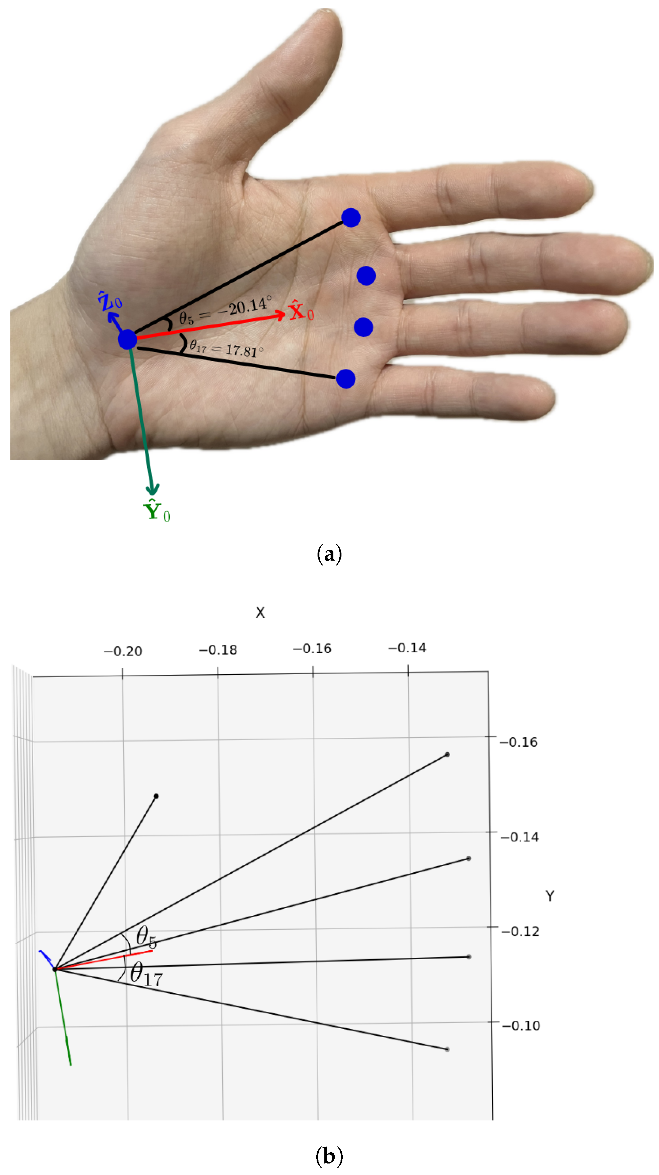
Given Equations (16) and (17), we calculate the angular parameters for the fingers relative to the wrist frame (Figure 8). By transforming the world coordinates of each finger base into the wrist coordinate frame, we can compute the corresponding angle parameters as follows:
d 1 0 = ( T 0 w ) 1 d 1 w = ( 0.0213 , 0.0380 , 0 ) θ 1 = arctan ( d 1 , y 0 , d 1 , x 0 ) = 1.06 radians = 60.68 d 5 0 = ( T 0 w ) 1 d 5 w = ( 0.0892 , 0.0327 , 0 ) θ 5 = arctan ( d 5 , y 0 , d 5 , x 0 ) = 0.35 radians = 20.14 d 9 0 = ( T 0 w ) 1 d 9 w = ( 0.0919 , 0.0119 , 0 ) θ 9 = arctan ( d 9 , y 0 , d 9 , x 0 ) = 0.13 radians = 7.38 d 13 0 = ( T 0 w ) 1 d 13 w = ( 0.0892 , 0.0062 , 0 ) θ 13 = arctan ( d 13 , y 0 , d 13 , x 0 ) = 0.07 radians = 4.03 d 17 0 = ( T 0 w ) 1 d 17 w = ( 0.0815 , 0.0262 , 0 ) θ 17 = arctan ( d 17 , y 0 , d 17 , x 0 ) = 0.31 radians = 17.81

4.2. Resolving Layered Parameters of Fingers in Hierarchical Transformations

In the kinematic model of the hand as introduced in previous section, the metacarpophalangeal (MCP), proximal interphalangeal (PIP), and distal interphalangeal (DIP) joints are organized within a hierarchical structure. Each joint’s local coordinate frame is derived from its parent joint’s frame, establishing a consistent chain of transformations from the base of the finger to the fingertip. This section provides a comprehensive explanation of how the parameters for these hierarchical transformations are resolved, detailing how each joint’s movement is propagated along the kinematic chain to accurately model finger rotations.
First Layer (at MCP Joints): Each MCP joint has two DOF, enabling it to bend up and down and move side to side; five pairs of rotation angles β i and γ i around axes Y ^ i and Z ^ i for the root joints of each finger are defined in the previous section. Thus, the orientation of local frames at MCP joints with respect to wrist frame { 0 } can be expressed as:
R i 0 = R z ( γ i ) R y ( β i ) = cos γ i sin γ i 0 sin γ i cos γ i 0 0 0 1 cos β i 0 sin β i 0 1 0 sin β i 0 cos β i = cos γ i cos β i sin γ i cos γ i sin β i sin γ i cos β i cos γ i sin γ i sin β i sin β i 0 cos β i = X ^ i 0 Y ^ i 0 Z ^ i 0 , i = 1 , 5 , 9 , 13 , 17
To compute the angles γ i and β i based on the rotation matrix R i 0 = X ^ i 0 Y ^ i 0 Z ^ i 0 , we can utilize the geometric relationship between these axes and the wrist frame’s axes. Along each of the five fingers, the axes X ^ for each of the three joints orient towards the origin of the next joint’s frame; therefore
X ^ i 0 = d i + 1 0 d i 0 d i + 1 0 d i 0 , i = 1 , 5 , 9 , 13 , 17
Based on the kinematic model we defined, the axes Y ^ i of the local frames for each finger align with the axes of the revolute joints, which are perpendicular to both the corresponding X ^ i and Z ^ 0 , the z-axis of the wrist. By computing the cross product of Z ^ 0 and X ^ i 0 , we get
Y ^ i 0 = Z ^ 0 × X ^ i 0 Z ^ 0 × X ^ i 0 , i = 1 , 5 , 9 , 13 , 17
Finally, the unit axes Z ^ i 0 of the local frames at the first layer are calculated as the cross product of the corresponding X ^ i 0 and Y ^ i 0 :
Z ^ i 0 = X ^ i 0 × Y ^ i 0 , i = 1 , 5 , 9 , 13 , 17
By integrating with the transformed position vectors d i 0 , we obtain the transformations at the first layer:
T i 0 = R i 0 d i 0 0 1 × 3 1 , i = 1 , 5 , 9 , 13 , 17 .
β i and γ i at the first layer can be extracted from the element in the third row, third column and the second row, second column of the rotation matrix R i 0 in Equation (19):
β i = arccos ( Z ^ i , z 0 ) γ i = arccos ( Y ^ i , y 0 ) , i = 1 , 5 , 9 , 13 , 17
Transformation to the First Layer of the Measured Index Finger: Based on Equations (19)–(24), the three principal unit vectors for the local frame { 5 } at the root of the index finger can be derived as follows:
X ^ 5 0 = d 6 0 d 5 0 d 6 0 d 5 0 = ( 0.0300 , 0.0048 , 0.0137 ) ( 0.0300 , 0.0048 , 0.0137 ) = ( 0.9006 , 0.1439 , 0.4102 ) Y ^ 5 0 = Z ^ 0 × X ^ 5 0 Z ^ 0 × X ^ 5 0 = ( 0.1439 , 0.9006 , 0 ) ( 0.1439 , 0.9006 , 0 ) = ( 0.1577 , 0.9875 , 0 ) Z ^ 5 0 = X ^ 5 0 × Y ^ 5 0 = ( 0.4050 , 0.0647 , 0.9120 )
We then form the rotation matrix R 5 0 using these unit vectors:
R 5 0 = X ^ 5 0 Y ^ 5 0 Z ^ 5 0 = 0.9006 0.1577 0.4050 0.1439 0.9875 0.0647 0.4102 0 0.9120 = R z ( γ 5 ) R y ( β 5 ) = cos γ 5 sin γ 5 0 sin γ 5 cos γ 5 0 0 0 1 cos β 5 0 sin β 5 0 1 0 sin β 5 0 cos β 5 = cos γ 5 cos β 5 sin γ 5 cos γ 5 sin β 5 sin γ i cos β 5 cos γ 5 sin γ 5 sin β 5 sin β 5 0 cos β 5
The angle parameters at the index finger MCP joint can now be calculated as:
β 5 = arccos ( Z ^ 5 , z 0 ) = arccos ( 0.9120 ) = 0.4227 radians = 24.22 γ 5 = arccos ( Y ^ 5 , y 0 ) = arccos ( 0.9875 ) = 0.1583 radians = 9.07
As shown in Figure 9, the local frame { 5 } , corresponding to the index finger MCP joint, can be described by a rotation relative to the wrist frame { 0 } first by 9.07 about Z ^ 0 and then by 24.22 about Y ^ 0 . Additionally, there is a translation of 0.0892 m along X ^ 0 and 0.0327 m along Y ^ 0 . The transformation matrix T 5 0 that defines the relationship between the index finger root and the wrist frame can be expressed as:
T 5 0 = R 5 0 d 5 0 0 1 × 3 1 = 0.9006 0.1577 0.4050 0.0892 0.1439 0.9875 0.0647 0.0327 0.4102 0 0.9120 0 0 0 0 1
This transformation provides the full description of the index finger’s MCP joint in relation to the wrist frame, accounting for both rotational and translational movements.
Second and Third Layer (at PIP and DIP Joints): Each of the five fingers can be modeled as a kinematic chain consisting of three links connected by three revolute joints, with parallel rotation axes. The PIP and DIP joints, which form the second and third layers of this chain, each possess a single DOF. Consequently, the rotation of each joint in these layers can be fully described by a single rotational parameter β j for the PIP joint and β j + 1 for the DIP joint, where j = 2 , 6 , 10 , 14 , 18 . These angles represent the flexion-extension motions at the respective joints and are defined as the angle between X ^ j and X ^ j 1 for the PIP joint and between X ^ j + 1 and X ^ j for the DIP joint.
Since all finger movements are considered locally within each kinematic chain, relative to the base frames of each finger root (i.e., { 1 } , { 5 } , { 9 } , { 13 } , and { 17 } ), the rotation angles will be computed based on the relative orientations of the joints within the preceding joint’s frame:
cos β j = X ^ j j 1 · X ^ j 1 j 1 X ^ j j 1 X ^ j 1 j 1 , j = 2 , 6 , 10 , 14 , 18 = ( d j + 1 j 1 d j j 1 ) · ( d j j 1 d j 1 j 1 ) d j + 1 j 1 d j j 1 d j j 1 d j 1 j 1 β j = arccos ( d j + 1 j 1 d j j 1 ) · ( d j j 1 d j 1 j 1 ) d j + 1 j 1 d j j 1 d j j 1 d j 1 j 1
where
d j j 1 = ( T j 1 0 ) 1 d j 0 d j + 1 j 1 = ( T j 1 0 ) 1 d j + 1 0
Similarly, for the angle parameters at the third layer:
cos β j + 1 = X ^ j + 1 j 1 · X ^ j j 1 X ^ j + 1 j 1 X ^ j j 1 , j = 2 , 6 , 10 , 14 , 18 = ( d j + 2 j 1 d j + 1 j 1 ) · ( d j + 1 j 1 d j j 1 ) d j + 2 j 1 d j + 1 j 1 d j + 1 j 1 d j j 1 β j + 1 = arccos ( d j + 2 j 1 d j + 1 j 1 ) · ( d j + 1 j 1 d j j 1 ) d j + 2 j 1 d j + 1 j 1 d j + 1 j 1 d j j 1
where
d j + 2 j 1 = ( T j 1 0 ) 1 d j + 2 0
The orientation matrix of the local frame at joint j relative to its parent joint j 1 is given by:
R j j 1 = R y ( β j ) , j = 2 , 6 , 10 , 14 , 18 = cos β j 0 sin β j 0 1 0 sin β j 0 cos β j
Similarly, the orientation matrix of the local frame at joint j + 1 (DIP joint) relative to joint j (PIP joint) is:
R j + 1 j = R y ( β j + 1 ) , j = 2 , 6 , 10 , 14 , 18 = cos β j + 1 0 sin β j + 1 0 1 0 sin β j + 1 0 cos β j + 1
By integrating the translation vectors, the relative positions of the joints can be expressed as:
d j j 1 = l j 1 , j 0 0 , d j + 1 j = l j , j + 1 0 0 , j = 2 , 6 , 10 , 14 , 18 .
The complete transformations at the second layer (PIP joint) and the third layer (DIP joint) are then obtained as follows:
T j j 1 = R j j 1 d j j 1 0 1 × 3 1 , T j + 1 j = R j + 1 j d j + 1 j 0 1 × 3 1 , j = 2 , 6 , 10 , 14 , 18 .
Transformations to the Second and Third Layer of the Measured Index Finger: Since all finger movements are modeled locally within each kinematic chain, relative to the base frames of each finger root, the rotation angles are computed based on the relative orientations of consecutive joints within the preceding joint’s frame. This hierarchical transformation approach ensures consistent rotational relationships between joints as they propagate along the kinematic chain.
First, the position vectors d 6 5 , d 7 5 and d 8 5 are calculated by transforming the parent wrist frame { 0 } into the local frame of the base joint (the MCP joint of the index finger, { 5 } ):
d 6 0 = ( T 0 w ) 1 d 6 w = ( 0.0892 , 0.0327 , 0 ) d 6 5 = ( T 5 0 ) 1 d 6 0 = ( 0.0333 , 0 , 0 ) d 7 5 = ( T 5 0 ) 1 d 7 0 = ( 0.0520 , 0.0016 , 0.0077 ) d 8 5 = ( T 5 0 ) 1 d 8 0 = ( 0.0679 , 0.0037 , 0.0114 ) .
To compute the rotation angle at the second layer (PIP joint), we perform a scalar product of the position vectors relative to the local frames. The angle β 6 is derived as follows:
cos β 6 = X ^ 6 5 · X ^ 5 5 X ^ 6 5 X ^ 5 5 = ( d 7 5 d 6 5 ) · ( d 6 5 d 5 5 ) d 7 5 d 6 5 d 6 5 d 5 5 β 6 = arccos ( 0.0187 , 0 , 0.0077 ) · ( 0.0333 , 0 , 0 ) ( 0.0187 , 0 , 0.0077 ) ( 0.0333 , 0 , 0 ) = 0.3877 radians = 22.22
For the angle parameters at the third layer (DIP joint), the rotation angle β 7 is computed similarly to the previous layer. Using the relative orientations of the joints, we can express β 7 as follows:
cos β 7 = X ^ 7 5 · X ^ 6 5 X ^ 7 5 X ^ 6 5 = ( d 8 5 d 7 5 ) · ( d 7 5 d 6 5 ) d 8 5 d 7 5 d 7 5 d 6 5 β 7 = arccos ( 0.0158 , 0 , 0.0038 ) · ( 0.0187 , 0 , 0.0077 ) ( 0.0158 , 0 , 0.0038 ) ( 0.0187 , 0 , 0.0077 ) = 0.1531 radians = 8.77
Here, each of β 6 = 22.22 and β 7 = 8.77 represents the flexion at the PIP and DIP joint of the index finger, as shown in Figure 10.
The orientation of the local frame { 6 } at the second joint (PIP joint) of the index finger relative to its parent joint (MCP joint) is represented by the matrix, which is defined by the rotation angle β 6 around the local Y ^ 6 -axis:
R 6 5 = R y ( β 6 ) = cos β 6 0 sin β 6 0 1 0 sin β 6 0 cos β 6 = 0.9258 0 0.3781 0 1 0 0.3781 0 0.9258
Similarly, the orientation matrix for the local frame { 7 } at the third joint (DIP joint) relative to the second joint (PIP joint) is:
R 7 6 = R y ( β 7 ) = cos β 7 0 sin β 7 0 1 0 sin β 7 0 cos β 7 = 0.9883 0 0.1525 0 1 0 0.1525 0 0.9883
The translational displacements between consecutive joints are defined by the following translation vectors:
d 6 5 = l 5 , 6 0 0 = 0.0333 0 0 , d 7 6 = l 6 , 7 0 0 = 0.0202 0 0
The complete transformation matrices at the second (PIP joint) and third layers (DIP joint) are constructed by combining the rotation matrices with the corresponding translation vectors. The transformation matrix from the MCP joint to the PIP joint is given by:
T 6 5 = R 6 5 d 6 5 0 1 × 3 1
Similarly, the transformation matrix from the PIP joint to the DIP joint is:
T 7 6 = R 7 6 d 7 6 0 1 × 3 1
Finally, note that the frame { 8 } is located at the fingertip and, by design, has no degrees of freedom (DOF). As a result, the transformation matrix from joint { 7 } (DIP joint) to the fingertip { 8 } is a simple identity matrix with a translation vector representing the fixed length between joint { 7 } and the fingertip { 8 } . This is given by:
T 8 7 = 1 0 0 l 7 , 8 0 1 0 0 0 0 1 0 0 0 0 1
Since there is no rotation or additional degrees of freedom at the fingertip, this transformation matrix simply translates the local frame by the fixed length l 7 , 8 , which represents the distance between the DIP joint and the fingertip. This final transformation completes the kinematic chain of the index finger, preserving the hierarchical structure of the transformations from the MCP joint to the fingertip.

5. Kinematic of Hand for Graphical Reconstruction in Unity

After resolving the kinematic parameters of the hand model, we implemented a reconstruction of a simulated human hand in Unity. Unity’s advanced rendering capabilities enable realistic, interactive visualizations, which are essential for validating the accuracy of both the hand model and the reconstruction process. By reconstructing the hand’s movement from the kinematic data, we can analyze the accuracy of joint movements, finger articulation, and interactions with objects in a virtual environment. In this section, we detail the process of implementing a rigged hand model in Unity, the definition of local coordinate frames, and the conversion of kinematic model parameters into Unity’s coordinate system.

5.1. Unity Environment and Rigged Hand Model

Unity version 2022.3.5f1 (Long-Term Support) was used to implement and visualize the reconstructed kinematic hand model. A rigged avatar hand model with 16 joints (one wrist joint and three joints for each of the five fingers) was imported from the Unity Asset Store. Each joint in the model is controlled via local coordinate frames and arranged hierarchically to reflect the anatomical structure of the human hand.
Scripts written in C# were developed to update joint rotations in real time using computed kinematic parameters. The Unity camera was aligned to mimic the depth sensor’s viewpoint, ensuring that tracked and reconstructed hand movements were spatially consistent. Due to Unity’s use of a left-handed coordinate system, we explicitly inverted the y-axis and transformed all rotational parameters accordingly to match the right-handed sensor coordinate system defined in Section 3.

5.2. Left-Handed Frame in Unity

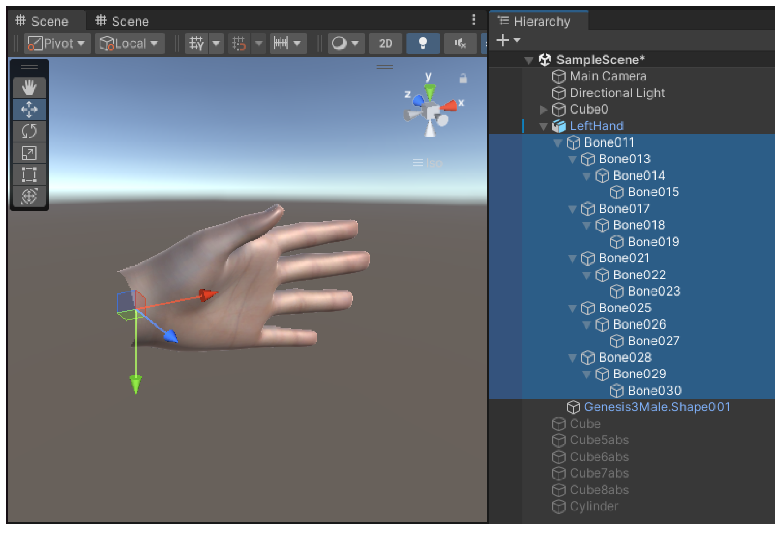
To graphically visualize hand movements, we utilize a rigged hand model in Unity, which replicates the actual texture and motion of the human hand. As shown in Figure 11, the hand model contains 16 movable joints, including the wrist and three joints for each of the five fingers ( 1 + 3 × 5 = 16 ) , excluding the fingertips.
In the rigged hand model, each joint is represented by a local coordinate frame { U } i , for i = 0 , 1 , , 15 that is oriented relative to the parent’s coordinate frame. The wrist frame { U } i , being the root joint, serves as the origin for the hand’s coordinate system. Each subsequent joint has its own local frame, which is updated based on the joint’s current orientation and position.
In Unity, a camera object defines the viewer’s perspective, capturing the scene and rendering 3D objects. In our setup, we define the camera’s coordinate frame as { U } , which corresponds to the depth sensor’s frame in the real-world setup. This camera object is positioned in Unity to mimic the physical sensor’s viewpoint, ensuring the virtual hand model moves in sync with real-world hand movements.
As stated previously, the world frame, denoted as { W } , is established at the center of the depth sensor and defined by three orthogonal axes: X ^ w , Y ^ w , and Z ^ w . In this setup, X ^ w points to the right, Y ^ w points downward, and Z ^ w extends outward from the sensor toward the objects being tracked.
However, Unity uses a left-handed coordinate system for its camera object, where X ^ u and Z ^ u in the camera frame { U } align with the X ^ w and Z ^ w of the world frame, respectively. The key difference is the orientation of the Y-axis: in Unity’s camera frame Y ^ u , it points upward, opposite to the downward-pointing Y ^ w in the world frame. This inversion must be accounted for when transforming the hand model’s parameters to ensure that the visualized hand movements in Unity accurately reflect the real-world hand tracked by the depth sensor.

5.3. Transformation from Hand Kinematic Model to Rigged Hand

Once the joint angles have been resolved in the kinematic model using the hierarchical structure of the hand, they need to be mapped to the corresponding joint angles in Unity.
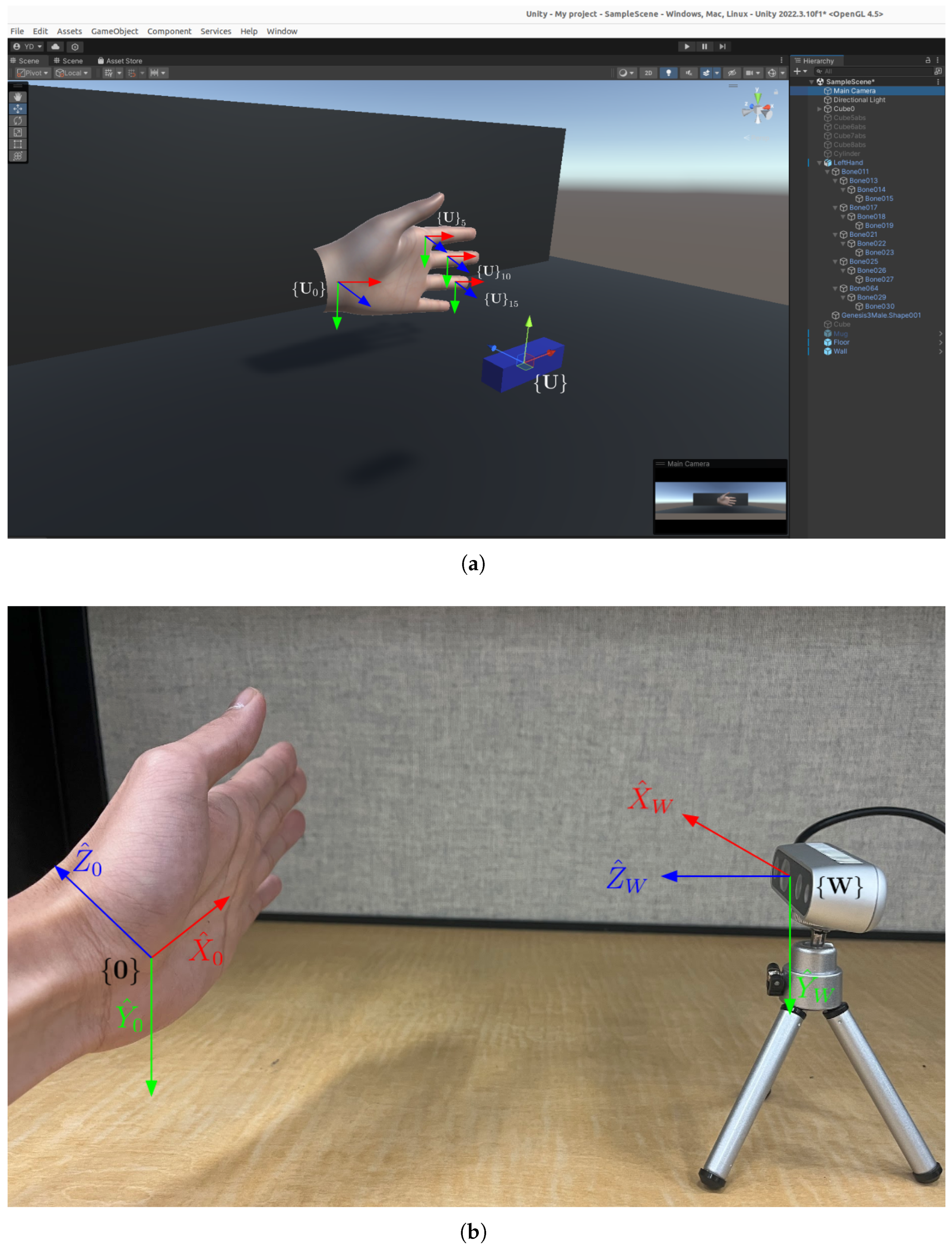
As shown in Figure 12, the local coordinate frames in the rigged hand model and the hand kinematic model are highly consistent in their definitions. Both models use a hierarchical structure, and the orientation of the x- and y-axes across the 16 joints is the same. However, a notable difference exists between the two models: the kinematic model utilizes a right-handed coordinate system, while the rigged hand model in Unity adopts a left-handed coordinate system. As a result, the z-axes in the two systems point in opposite directions. In the rigged hand model, the z-axis points perpendicular to the palm, facing toward the camera, whereas in the kinematic model, the z-axis points away from the hand and the camera.
Thus, in order to properly reconstruct hand movements in Unity, the parameters from the kinematic model must undergo a transformation. This transformation involves two key steps: coordinate transformation and local frame transformation.
Coordinate Transformation: If a point p has coordinates p r = ( p x , p y , p z ) in the right-handed coordinate system O r , and we define a left-handed coordinate system O l at the same origin with the same x- and y-axes but with the z-axis pointing in the opposite direction, the coordinates of the point p in the left-handed coordinate system will be p l = ( p x , p y , p z ) . In matrix form, this transformation can be expressed as:
p l = p x p y p z = 1 0 0 0 1 0 0 0 1 p x p y p z = R r l p r
where the transformation matrix to switch from a right-hand system to a left-hand system is as follows:
R r l = 1 0 0 0 1 0 0 0 1
This transformation accounts for the difference in the handedness of the two coordinate systems, ensuring that the joint positions in Unity’s left-handed frame correctly correspond to the real-world positions tracked by the right-handed kinematic model.
Local Frame Transformation: Since the rigged hand and the kinematic hand model differ in their local coordinate frame conventions, the rotation matrices for each joint must also be transformed to reflect this change. Consider a local coordinate frame { O } in the right-handed system O r , where its orientation is represented by the rotation matrix R r . At the origin of this right-handed coordinate system O r , we can define a corresponding left-handed coordinate system O l where the x- and y-axes remain the same, but the z-axis points in the opposite direction. We now seek to compute the orientation matrix R l for the local coordinate frame { O } in this left-handed system.
Let p r represent an arbitrary point in the right-handed system. After applying the rotation matrix, the transformed point in O r is:
p r = R r p r
In the left-handed coordinate system O l , the corresponding points before and after rotation are represented by:
p l = R r l p r , p l = R r l p r
Therefore, the transformed point p l in the left-handed system can be expressed as:
p l = R r l p r = R r l R r p r = R r l R r R r l 1 p l
Thus, the orientation matrix of the local coordinate frame O in the left-handed system O l is:
R l = R r l R r R r l 1
Since the matrix R r l represents a reflection operation, and reflections are involuntary transformations (applying them twice returns the original state). When we multiply R r l by itself:
R r l · R r l = 1 0 0 0 1 0 0 0 1 · 1 0 0 0 1 0 0 0 1 = 1 0 0 0 1 0 0 0 1 = I
It follows that:
R r l = R r l 1
In summary, to transform the hand kinematic model’s local coordinate frames to the rigged hand’s left-handed coordinate system in Unity, the orientation matrix for each of the 16 joints must be transformed using Equation (51). This ensures that all joint rotations and movements are accurately mapped from the real-world right-handed system to Unity’s left-handed system. For example, using the rotational transformation matrices R 5 0 , R 6 5 , R 7 6 defined in the previous section using measured data, we can compute their corresponding rotation matrix in left-handed coordinate system:
R 5 l 0 = R r l R 5 r 0 R r l 1 = 1 0 0 0 1 0 0 0 1 0.9006 0.1577 0.4050 0.1439 0.9875 0.0647 0.4102 0 0.9120 1 0 0 0 1 0 0 0 1 = 0.9006 0.1577 0.4050 0.1439 0.9875 0.0647 0.4102 0 0.9120
R 6 l 5 = R r l R 6 r 5 R r l 1 = 1 0 0 0 1 0 0 0 1 0.9258 0 0.3781 0 1 0 0.3781 0 0.9258 1 0 0 0 1 0 0 0 1 = 0.9258 0 0.3781 0 1 0 0.3781 0 0.9258
R 7 l 6 = R r l R 7 r 6 R r l 1 = 1 0 0 0 1 0 0 0 1 0.9883 0 0.1525 0 1 0 0.1525 0 0.9883 1 0 0 0 1 0 0 0 1 = 0.9883 0 0.1525 0 1 0 0.1525 0 0.9883

5.4. Quaternions Representation for Joint Rotations

In Unity, rotations are most effectively represented using quaternions. Quaternions offer a robust method to represent rotations without suffering from gimbal lock, which can occur when using Euler angles. A quaternion is defined by four components: ( w , x , y , z ) , where w represents the scalar part, and ( x , y , z ) forms the vector part, indicating the axis of rotation.
Given a rotation matrix obtained from the kinematic model, the corresponding quaternion is derived as follows:
q = w , x , y , z = cos θ 2 , u x sin θ 2 , u y sin θ 2 , u z sin θ 2
where θ is the rotation angle, and u = ( u x , u y , u z ) is the normalized axis of rotation. This representation ensures that all joint rotations are smooth and efficient for computational purposes in Unity.
To convert a 3 × 3 rotation matrix into a quaternion, the components of the quaternion are calculated from the matrix elements [18]. The matrix is of the form:
m 00 m 01 m 02 m 10 m 11 m 12 m 20 m 21 m 22
and the quaternion components are computed as:
q w = max ( 0 , 1 + m 00 + m 11 + m 22 ) 2 q x = max ( 0 , 1 + m 00 m 11 m 22 ) 2 q y = max ( 0 , 1 m 00 + m 11 m 22 ) 2 q z = max ( 0 , 1 m 00 m 11 + m 22 ) 2
Finally, the signs of q x , q y , and q z are adjusted based on the off-diagonal elements of the rotation matrix to ensure consistency with the direction of rotation:
q x = q x · sign ( q x · ( m 21 m 12 ) ) q y = q y · sign ( q y · ( m 02 m 20 ) ) q z = q z · sign ( q z · ( m 10 m 01 ) )
Therefore,
R 5 l 0 = 0.9006 0.1577 0.4050 0.1439 0.9875 0.0647 0.4102 0 0.9120
produces
q 5 w = max ( 0 , 1 + 0.9006 + 0.9875 + 0.9120 ) 2 = 0.9747 q 5 x = max ( 0 , 1 + 0.9006 0.9875 0.9120 ) 2 = 0.0166 q 5 y = max ( 0 , 1 0.9006 + 0.9875 0.9120 ) 2 = 0.2091 q 5 z = max ( 0 , 1 0.9006 0.9875 + 0.9120 ) 2 = 0.0773
and
q 5 x = q 5 x · sign ( q 5 x · ( 0 0.0647 ) ) = 0.0166 q 5 y = q 5 y · sign ( q 5 y · ( 0.4050 0.4102 ) ) = 0.2091 q 5 z = q 5 z · sign ( q 5 z · ( 0.1439 0.1577 ) ) = 0.0773
Finally,
q 5 = ( 0.9747 , 0.0166 , 0.2091 , 0.0773 ) q 6 = ( 0.9813 , 0 , 0.1927 , 0 ) q 7 = ( 0.9971 , 0 , 0.0765 , 0 )
While the current implementation assumes full visibility of all 21 landmarks, we acknowledge that occlusions—either from self-shadowing or external objects—can impair direct observation of certain joint positions. The proposed kinematic model, by establishing a hierarchical and constraint-based structure, allows for integration with future estimation methods such as Bayesian networks or optimization schemes to infer occluded landmarks. Addressing such occlusion scenarios is a natural extension of this work.

6. Discussions and Conclusions

6.1. Discussions

This paper presents various steps in developing a kinematic model of a dexterous hand using hand-pose-tracking data augmented with depth measures. The modeling method and the corresponding kinematic solutions were demonstrated through various measured data in resolving a hand kinematic parameters from captured RGB-D data. The 21 landmarks detected by MediaPipe were identified using calibrated RGB images where the corresponding depth values were measured (Figure 13). However, it was observed that as the hand moves, the data tends to become noisy. For instance, when the hand moves along a trajectory from the top left to the bottom right of the image, while MediaPipe continues to detect the 21 landmarks consistently, the associated depth values can contain outliers or even return invalid zero values. These discrepancies in the depth data can arise from factors such as occlusions, rapid hand movements, or limitations in the sensor’s precision.
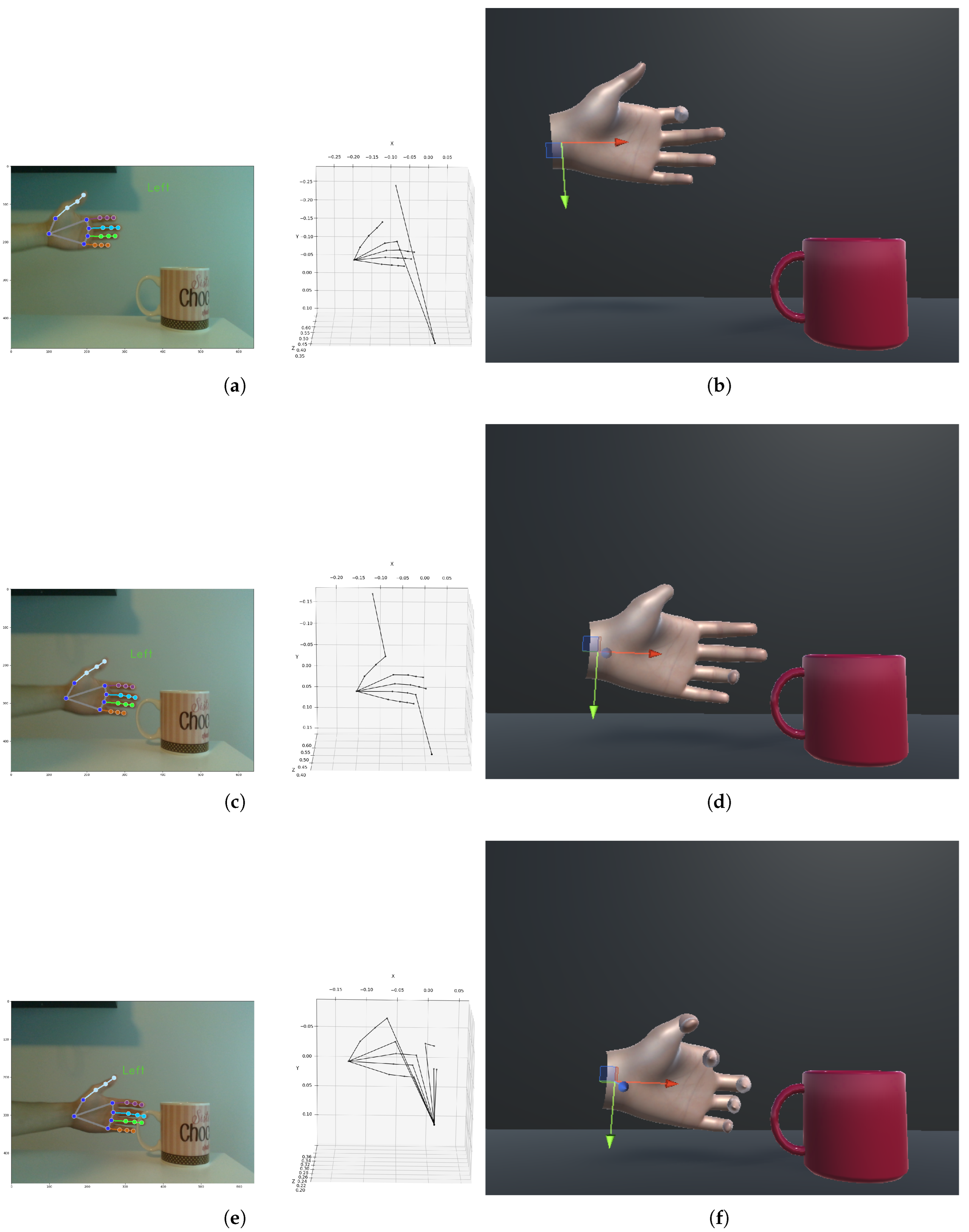
As an example, Figure 14 illustrates the process of the hand approaching a cup in three consecutive stages. In Figure 14a, the last two joints of the index finger show irregular depth data: one is recorded as 0, and the other as a far-off value (likely the distance to the white wall behind the hand, instead of the finger itself). In Figure 14b, the corresponding reconstruction in Unity shows the misalignment, where the index finger in the virtual hand model differs from the actual position of the real index finger. In Figure 14c, depth outliers are detected in both the thumb and the ring finger, resulting in erroneous positioning. The Unity reconstruction in Figure 14d reflects this discrepancy. In Figure 14e, as the fingertips of four fingers are slightly occluded by the cup’s handle, their depth values are recorded as 0. This further contributes to inaccuracies in the Unity reconstruction, as shown in Figure 14f, where the fingers deviate from their true positions due to the occlusion-induced depth errors.
To address such issues in proper kinematic resolutions, the use of prior knowledge, such as fixed user’s finger lengths, and the use of inverse kinematic model as constraints can be used to better estimate missing and erroneous landmarks. This can offer an approach to calculate the best angular parameters for reconstructing accurate hand movements in Unity, even when sensor data is incomplete or noisy.

6.2. Conclusions and Future Work

This paper presents a structured methodology for constructing a 3D kinematic model of the human hand based on spatially calibrated landmark data. The proposed model establishes a hierarchical coordinate system rooted at the palm and resolves both forward and inverse kinematic parameters for each finger joint. These results are integrated into a graphical reconstruction framework in Unity, enabling qualitative validation through simulated hand visualization. The main contributions of this work include the formulation of a hierarchical kinematic model driven by real-world sensor data, the derivation of joint parameters through geometric transformations, and the demonstration of pose reconstruction using a visualization platform.
While the current study focuses on single-subject modeling and offline data, future research will expand the framework in several directions [19,20]. We plan to incorporate wearable motion-capture devices to obtain ground-truth joint measurements, which will allow for a quantitative evaluation of the model’s accuracy. Comparative studies with state-of-the-art hand-pose estimation techniques will also be conducted to benchmark performance under various conditions, including sensor noise and occlusion. Additionally, we aim to extend the system for real-time tracking and modeling across different users, capturing dynamic hand interactions more effectively. To enhance robustness, we intend to integrate model-based estimation with data-driven methods such as neural networks or Bayesian inference frameworks. Finally, we envision applications of the proposed model in rehabilitation monitoring, and teleoperation systems, where accurate and interpretable hand motion representation is crucial. These extensions will further strengthen the generalizability and practical relevance of the presented approach.

Author Contributions

Conceptualization, S.P.; methodology, S.P. and Y.D.; software, Y.D.; validation, Y.D.; resources, S.P.; original draft preparation, S.P. and Y.D.; writing—review and editing, S.P. and Y.D.; visualization, Y.D.; supervision, S.P.; funding acquisition, S.P. All authors have read and agreed to the published version of the manuscript.

Funding

The research was funding through the Natural Sciences and Engineering Research Council of Canada.

Data Availability Statement

Dataset available on request from the authors.

Conflicts of Interest

The authors declare no conflict of interest.

Appendix A. Camera Calibration and RGB-Depth Pixel Association

This appendix provides a detailed explanation of the process to associate 2D pixels in the RGB stream with corresponding depth information. We utilize both the intrinsic and extrinsic calibration parameters of the intel RealSense D435 sensors, which enable the projection of 2D pixels to 3D space and subsequently map these 3D coordinates between the depth and RGB camera coordinate systems.

Appendix A.1. Intrinsic and Extrinsic Calibration

In a multi-sensing systems, the correct association of pixel information across different sensor modalities (e.g., RGB and depth) relies on accurate calibration. Camera calibration involves both intrinsic and extrinsic parameters:
Intrinsic parametersdefine the internal characteristics of each camera, such as f x and f y are the focal length of the camera in the x and y directions. c x and c y are the principal point offsets (the center of the image plane).
For the RGB and depth cameras of D435, the intrinsic calibration matrices are given as:
  • RGB camera intrinsics:
    K r g b = f x 0 c x 0 f y c y 0 0 1 = 609.625 0 323.445 0 609.671 247.874 0 0 1
  • Depth camera intrinsics:
    K d e p t h = f x 0 c x 0 f y c y 0 0 1 = 388.665 0 320.381 0 388.665 244.883 0 0 1
These parameters are for projecting pixel coordinates from image space to camera space.
Extrinsic parameters describe the geometric relationship between the RGB and depth cameras in terms of rotation and translation. The transformation between the two sensing coordinate systems is expressed through the following extrinsic matrix:
P r g b = R · P d e p t h + t
where R is the rotation matrix and t is the translation vector:
R = 0.999976 0.006945 0.000594 0.006944 0.999975 0.001545 0.000605 0.001541 0.999999 I , t = 0.0147 0.0003 0.0004
The rotation matrix R captures the orientation difference between the sensors, while the translation vector t accounts for the physical position discrepancies. These extrinsic parameters are essential for transforming 3D coordinates from the depth camera space to the RGB camera space. Based on the extrinsic parameters given, it suggests that the RGB and depth cameras are closely aligned in both orientation and position. The values in R are very close to an identity matrix (i.e., 1 on the diagonal and very close to 0 for the off-diagonal elements). This indicates that the depth and RGB cameras have almost no relative rotation transformation with respect to each other. The minor deviations from 1 and 0 on diagonals reflect a very small rotational misalignment, which could be due to slight manufacturing tolerances. The largest translation is along the x-axis (about 1.47 cm). This is typical in many stereo camera set-ups, where the cameras are placed side by side with a small baseline distance between them. The translations along the y-axis (0.03 cm) and z-axis (0.04 cm) are very small, indicating that the cameras are nearly aligned along the vertical and depth axes.

Appendix A.2. Aligning Depth to RGB Stream of the Sensor

In the RealSense SDK, aligning the depth frame to the RGB (color) frame involves transforming the 3D points corresponding to depth values into the RGB camera’s coordinate system. This ensures that for each pixel in the RGB image, there is a corresponding pixel in the depth image, allowing us to associate depth information with color data accurately. Therefore, we can directly access associated depth value of each ( u , v ) from RGB stream and project 2D pixels to 3D space based on intrinsic parameters of RGB camera.
Projecting 2D Pixels to 3D Space (in cm)—A depth frame provides the distance d ( u , v ) from the camera to the surface at each pixel ( u , v ) . The depth image is stored as a 2D array:
D = { d ( u , v ) u [ 0 , w 1 ] , v [ 0 , h 1 ] }
where h is the image height, and w is the image width. These are based on the resolution configuration of the camera stream.
Given a pixel ( u , v ) from the RGB image and its associated depth value d ( u , v ) , we first project this 2D pixel to its corresponding 3D position ( x , y , z ) in the camera’s coordinate system. The projection is governed by the following equations, utilizing the intrinsic matrix K:
x ( u , v ) = ( u c x ) · d ( u , v ) f x
y ( u , v ) = ( v c y ) · d ( u , v ) f y
z ( u , v ) = d ( u , v )
The result is a 3D point ( x ( i , j ) , y ( i , j ) , z ( i , j ) ) for each pixel in the depth image, forming the point cloud of the scene.
Numerical Example—The camera has the following intrinsic parameters:
  • Image resolution: 640 × 480 pixels.
  • Focal length: f x = 609.62 , f y = 609.67 .
  • Principal point: c x = 323.44 , c y = 247.87 .
Given a pixel ( u = 84 , v = 120 ) of a wrist landmark with a depth value d ( 84 , 120 ) = 0.54 m , the 3D coordinates of the point can be computed as follows:
x ( 84 , 120 ) = ( 84 323.44 ) · 0.54 609.62 = 0.21 m
y ( 88 , 120 ) = ( 120 247.87 ) · 0.54 609.67 = 0.11 m
z ( 88 , 120 ) = 0.54 m
Thus, the 3D point corresponding to pixel ( 88 , 120 ) is ( 0.21 , 0.11 , 0.54 ) m.

References

  1. Rahman, M.M.; Uzzaman, A.; Khatun, F.; Aktaruzzaman, M.; Siddique, M. A comparative study of advanced technologies and methods in hand gesture analysis and recognition systems. Expert Syst. Appl. 2025, 266, 125929. [Google Scholar] [CrossRef]
  2. Amprimo, G.; Masi, G.; Pettiti, G.; Olmo, G.; Priano, L.; Ferraris, C. Hand tracking for clinical applications: Validation of the Google MediaPipe Hand (GMH) and the depth-enhanced GMH-D frameworks. Biomed. Signal Process. Control 2024, 96 Pt A, 106508. [Google Scholar] [CrossRef]
  3. Diaz, C.; Payandeh, S. Preliminary Experimental Study of Marker-based Hand Gesture Recognition System. J. Autom. Control Eng. 2014, 2, 242–249. [Google Scholar] [CrossRef]
  4. Wang, J.; Payandeh, S. Hand Motion and Posture Recognition in a Network of Calibrated Cameras. Adv. Multimed. 2017, 1, 1–25. [Google Scholar] [CrossRef]
  5. Rehg, J.M.; Kanade, T. DigitEyes: Vision-based hand tracking for human-computer interaction. In Proceedings of the 1994 IEEE Workshop on Motion of Non-Rigid and Articulated Objects, Austin, TX, USA, 11–12 November 1994; pp. 16–22. [Google Scholar] [CrossRef]
  6. Rehg, J.M.; Kanade, T. Visual tracking of high DOF articulated structures: An application to human hand tracking. In Computer Vision — ECCV’94, Lecture Notes in Computer Science; Eklundh, J.O., Ed.; Springer: Berlin/Heidelberg, Germany, 1994; Volume 801, pp. 35–46. [Google Scholar] [CrossRef]
  7. Isaac, J.H.; Manivannan, M.; Ravindran, B. Corrective Filter Based on Kinematics of Human Hand for Pose Estimation. Front. Virtual Real. 2021, 2, 663618. [Google Scholar] [CrossRef]
  8. Li, T.; Xiong, X.; Xie, Y.; Hito, G.; Yang, X.; Zhou, X. Reconstructing Hand Poses Using Visible Light. Proc. Acm Interactive Mobile Wearable Ubiquitous Technol. 2017, 1, 71. [Google Scholar] [CrossRef]
  9. Cerveri, P.; De Momi, E.; Lopomo, N.; Baud-Bovy, G.; Barros, R.M.L.; Ferrigno, G. Finger Kinematic Modeling and Real-Time Hand Motion Estimation. Ann. Biomed. Eng. 2007, 35, 1989–2002. [Google Scholar] [CrossRef] [PubMed]
  10. Haustein, M.; Blanke, A.; Bockemühl, T.; Bockemühl, A. A leg model based on anatomical landmarks to study 3D joint kinematics of walking in Drosophila melanogaster. Front. Bioeng. Biotechnol. Sec. Biomech. 2024, 12, 1357598. [Google Scholar] [CrossRef] [PubMed]
  11. Ji, Y.; Li, H.; Yang, Y.; Li, S. Hierarchical topology based hand pose estimation from a single depth image. Multimed. Tools Appl. 2018, 77, 10553–10568. [Google Scholar] [CrossRef]
  12. Peña-Pitarch, E.; Falguera, N.T.; Yang, J. Virtual human hand: Model and kinematics. Comput. Methods Biomech. Biomed. Eng. 2012, 17, 568–579. [Google Scholar] [CrossRef] [PubMed]
  13. Zimmermann, C.; Brox, T. A Hybrid Model for Real-Time 3D Hand Pose Estimation. In Proceedings of the IEEE/CVF Conference on Computer Vision and Pattern Recognition Workshops (CVPRW), Nashville, TN, USA, 19–25 June 2021. [Google Scholar]
  14. Lapresa, M.; Zollo, L.; Cordella, F. A user-friendly automatic toolbox for hand kinematic analysis, clinical assessment and postural synergies extraction. Front. Bioeng. Biotechnol. 2022, 10, 1–16. [Google Scholar] [CrossRef] [PubMed]
  15. Xu, Y.; Lee, G.H. Probabilistic Modeling of Hand Pose Under Occlusions with Anatomical Constraints. In Proceedings of the IEEE/CVF International Conference on Computer Vision (ICCV), Paris, France, 1–6 October 2023. [Google Scholar]
  16. Pfisterer, A.; Li, X.; Mengers, V.; Brock, O. A Helping (Human) Hand in Kinematic Structure Estimation. arXiv 2025, arXiv:2503.05301. [Google Scholar] [CrossRef]
  17. Zhang, F.; Bazarevsky, V.; Vakunov, A.; Tkachenka, A.; Sung, G.; Chang, C.L.; Grundmann, M. MediaPipe Hands: On-device Real-time Hand Tracking. arXiv 2020, arXiv:2006.10214. [Google Scholar] [CrossRef]
  18. Shoemake, K. Animating rotation with quaternion curves. ACM SIGGRAPH Comput. Graph. 1985, 19, 245–254. [Google Scholar] [CrossRef]
  19. Ahmad, A.; Migniot, C.; Dipanda, A. Tracking Hands in Interaction with Objects: A Review. In Proceedings of the 13th International Conference on Signal-Image Technology & Internet-Based Systems (SITIS), Jaipur, India, 4–7 December 2017; pp. 360–369. [Google Scholar] [CrossRef]
  20. Cheng, W.; Kim, E.; Ko, J.H. HandDAGT: A Denoising Adaptive Graph Transformer for 3D Hand Pose Estimation. In Proceedings of the European Conference on Computer Vision (ECCV), Milan, Italy, 29 September–4 October 2024. in press. [Google Scholar]
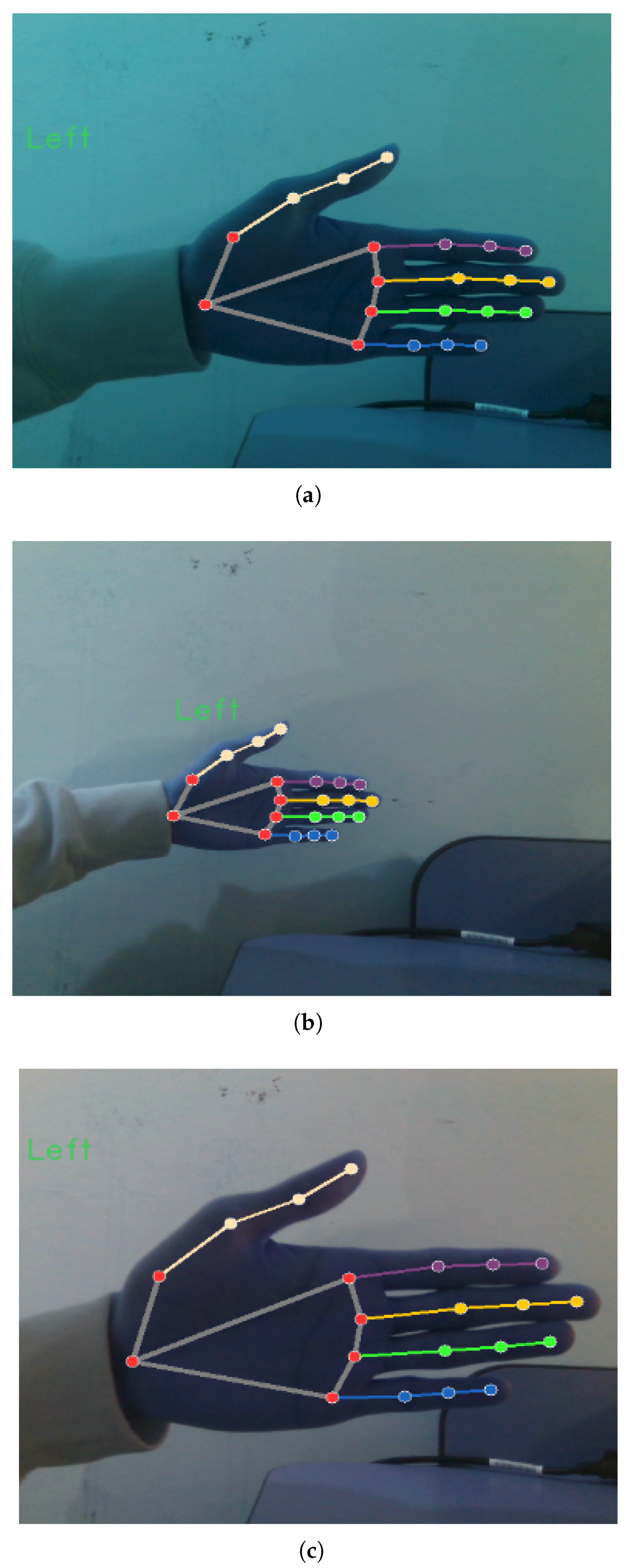
Figure 1. Three screenshots of hand movement at the start, middle, and ending points. (a) The hand starts to move from approximately 0.35 m near the sensor. (b) The hand reaches a distance of around 0.50 m and begins to move back. (c) The hand is near the sensor again, stopping at around 0.25 m.
Applsci 15 08921 g001
Figure 2. Comparison of depth values (a) estimated by MediaPipe and (b) measured by RealSense D435 sensor for wrist point (landmark 0) over time.
Applsci 15 08921 g002
Figure 3. An example of principal axes of the local wrist frame { 0 } (attached to the hand) and the world frame { W } (attached to the sensor).
Applsci 15 08921 g003
Figure 4. Hierarchical local frames { 0 } to { 20 } and parameters of the hand palm.
Applsci 15 08921 g004
Figure 5. Assignments of local frames { 5 } to { 8 } on the index finger. (a) A frontal view (with slight rotation offset) of a straight index finger. (b) lateral view of a bent index finger.
Applsci 15 08921 g005
Figure 6. A visualization of the 2D pixels of MediaPipe hand tracking and 3D spatial points.
Applsci 15 08921 g006
Figure 7. An example of the coordinate of palm frame located at landmark { 0 } . (a,c) Frontal view (demonstrates a slight counter-clockwise rotation ( 8.06 ) of the hand around Z ^ w ). (b,d) Side view (demonstrates a counter-clockwise rotation ( 22.14 ) around Y ^ w and a slight clockwise rotation ( 14.44 ) around the X ^ w ).
Applsci 15 08921 g007
Figure 8. (a,b) Visualization of the computation for the angle parameters θ 5 = 20.14 and θ 17 = 17.81 which is a rotation around Z ^ 0 of the measured hand palm. (a) Palm frontal view and (b) its associated landmark coordinates representation.
Applsci 15 08921 g008
Figure 9. Axes of frames { 0 } and { 5 } of the palm. (a,c) frontal view (verifies a slight clockwise ( 9.07 ) rotation of the hand around Z ^ 0 ). (b,d) side view (verifies a clockwise rotation ( 24.22 ) around Y ^ 0 ).
Applsci 15 08921 g009aApplsci 15 08921 g009b
Figure 10. (a,b) shows axes of frames { 5 } , { 6 } and { 7 } of the index finger, which confirms a natural clockwise rotation of 22.22 and a slight clockwise rotation of 8.77 around the parallel rotational axis Y ^ at PIP joint and DIP joint).
Applsci 15 08921 g010
Figure 11. Avatar hand model and hierarchical frame in Unity.
Applsci 15 08921 g011
Figure 12. A comparison of frame definition in the rigged hand and kinematic model. (a) Unity model and local frames in the rigged hand. (b) World and local frames in the hand kinematic model.
Applsci 15 08921 g012
Figure 13. (Left): (a) shows a sample MediaPipe output visualizing the 21 detected hand landmarks overlaid on RGB-D data. (b) shows Unity visualization of the hand model reconstructed using the resolved kinematic parameters, synchronized with the real hand’s movement.
Applsci 15 08921 g013
Figure 14. Consecutive stages of a hand approaching a cup, demonstrating depth inaccuracies and their effect on the Unity reconstruction. The key distinction lies in the corrupted depth input, shown in (a,c,e), which leads to deviation in the reconstructed kinematic pose, shown in (b,d,f), highlighting the impact of sensor noise on the estimation process.
Applsci 15 08921 g014
Table 1. Measured 3D spatial coordinates d i w of 21 hand landmarks (in meters).
JointsMCP
(1st Layer)
PIP
(2nd Layer)
DIP
(3rd Layer)
Tip
(4th Layer)
Finger
Wrist d 0 w
Thumb d 1 w d 2 w d 3 w d 4 w
Index d 5 w d 6 w d 7 w d 8 w
Middle d 9 w d 10 w d 11 w d 12 w
Ring d 13 w d 14 w d 15 w d 16 w
Little d 17 w d 18 w d 19 w d 20 w
Table 2. An measured example of 3D spatial coordinates d i w of 21 hand landmarks.
JointsMCP
(1st Layer)
PIP
(2nd Layer)
DIP
(3rd Layer)
Tip
(4th Layer)
Finger
Wrist(−0.21, −0.11, 0.54)
Thumb(−0.19, −0.15, 0.53 )(−0.17, −0.18, 0.54)(−0.15, −0.20, 0.55)(−0.14, −0.22, 0.56)
Index(−0.13, −0.16, 0.56)(−0.10, −0.16, 0.56)(−0.08, −0.16, 0.55)(−0.06, −0.16, 0.55)
Middle(−0.13, −0.14, 0.57)(−0.09, −0.14, 0.57)(−0.07, −0.14, 0.56)(−0.05, −0.14, 0.55)
Ring(−0.13, −0.12, 0.57)(−0.10, −0.12, 0.57)(−0.07, −0.12, 0.56)(−0.06, −0.12, 0.56)
Little(−0.14, −0.10, 0.57)(−0.11, −0.10, 0.57)(−0.09, −0.10, 0.57)(−0.07, −0.10, 0.57)
Disclaimer/Publisher’s Note: The statements, opinions and data contained in all publications are solely those of the individual author(s) and contributor(s) and not of MDPI and/or the editor(s). MDPI and/or the editor(s) disclaim responsibility for any injury to people or property resulting from any ideas, methods, instructions or products referred to in the content.