Abstract
To address the challenges of controlling coal roadway roofs with large spans, this study employed theoretical analysis, mechanical modeling, numerical simulation, and field testing to investigate the deformation and failure modes of large-span roadway roofs. An elastic foundation beam model for roof deformation under area support was established. The critical time-effective roof control principle and technology based on area support were proposed. Numerical simulation research and field trials of critical time-effective roof control using area support were conducted in the tailgate (open-off cut) of Panel II513 at the Huaibei Shuanglong Coal Mine. The results indicate that roof stability decreases with decreasing rock beam thickness and increasing span. The deformation and failure modes of large-span roadway roofs include anchor failure within the anchored zone and delamination outside the anchored zone. Case studies based on the mechanical model, numerical simulations, and field tests all demonstrate that the critical time-effective roof control technology utilizing hydraulic support for area support can significantly reduce roof deflection deformation.
1. Introduction
The technological transformation toward intelligent coal mining is a crucial direction for scientific innovation in China’s coal industry, as well as globally. With the rapid advancement of mechanization, automation, and intelligence in coal mines [1], mining equipment is also developing toward integration and large scale. To meet the requirements for equipment passage and safe, efficient coal production, the dimensions of development roadways need to be increased accordingly [2]. To ensure normal transportation, ventilation, and pedestrian requirements, development roadways typically have spans exceeding 5 m, with tailgates (open-off cuts) for placing mining equipment often exceeding 8 m in span. Span is a primary factor influencing the stability of roadways’ surrounding rock. Increasing span leads to intensified deformation of the surrounding rock and a higher risk of instability and failure [3]. Therefore, the study of the deformation and failure mode and control technology of the roof in large-span coal seam roadways is of great significance for ensuring the safe and efficient production of coal and promoting technological innovation in the coal industry.
The maximum deterioration depth of a roadway roof is approximately two-thirds of the span; deterioration in deeper roof strata only occurs when excessive deformation of the shallow roof is allowed [4]. Buckling beam theory shows that the load-bearing capacity of a roof rock beam is inversely proportional to the square of the roadway span [5]. This implies that a roof-anchored layer thickness reaching two-thirds of the span can maximize the avoidance of deep-seated deterioration. It also means that larger roadway spans increase the likelihood of roof instability and the difficulty of roof support. Furthermore, roof cementation conditions, interlayer situations, and water environment also affect the load-bearing capacity of the roof rock beam, undoubtedly further increasing the difficulty of controlling large-span roadway roofs [6,7,8,9].
After roadway excavation, rock masses at different shallow levels of the roof experience varying degrees of stress attenuation and damage deformation. The degree of discontinuous deformation gradually decreases with increasing roof depth until the roof rock mass exhibits continuous deformation [10]. As the roadway span increases, the depth of the discontinuous deformation zone tends to extend upward [11]. To inhibit discontinuous deformation of the roof and prevent roof collapse and instability, Zhang et al. [12] proposed the continuous beam control theory for coal roadways. This involves constructing a thick, pre-stressed, anchored rock beam in the roadway roof promptly, exceeding the range of the discontinuous deformation zone. However, when the roadway span exceeds a certain threshold, length-limited rock bolts struggle to meet the requirements for a thick, continuous beam. Xie et al. [13] developed a flexible long bolt not restricted by roadway height and capable of rapid installation. They determined the optimal specifications through performance testing and analysis and finally applied the flexible long bolt successfully for large-section roadway support. Han et al. [14], to address mining face disturbance, proposed a novel double-layer flexible support technology based on the continuous beam control theory. The first layer of flexible support forms a thicker base anchored layer, and the second layer forms a thicker reinforced anchored layer, effectively improving the roof’s resistance to disturbance. Li et al. [15] also proposed a multi-level pre-stressed arch support technology combining large and small structures composed of high-strength bolts and high pre-stressed cables. Xie et al. [16] proposed a deep beam anchorage structure for the roof, combining shallow bolt anchoring layers with deep cables. Whether using single thick-layer support or multi-level composite support [17,18,19], the purpose is to build a thick anchored load-bearing structure, enhance self-bearing capacity, and thereby achieve surrounding rock stability [20]. To solve the control problem of development roadways under the influence of advanced abutment pressure from fully mechanized faces, Jin et al. [21] determined an advanced support scheme using single hydraulic props combined with π-shaped steel beams through mechanical analysis and numerical simulation. Han et al. [22] enhanced bearing capacity by improving concrete strength and contact tightness with steel pipes, developing a new type of high-strength concrete-filled steel tubular (CFST) column. This achieved good support effects when used for large-span development roadway roofs. Ding et al. [23] designed a novel, highly adaptable advanced support for fully mechanized mining, enabling rapid and flexible movement of the support, providing new ideas for advanced support in fully mechanized roadways. Liu et al. [24] adopted double rows of chock-type supports to increase the stiffness of the support system and control roof settlement deformation in gob-side entry retaining with roof cutting.
In summary, there are two main approaches to addressing the roof control challenges in coal roadways caused by large spans. The first is to construct a thick anchored structure through active support sufficient to resist the various risks brought by large spans. The second is to use passive support to achieve “area control” of the roof, restricting its downward deformation and effectively dividing it into two small-span roadways, i.e., “span reduction through area control”. This paper takes the tailgate of Panel II513 at the Huaibei Shuanglong Coal Mine as the background to explore large-span roadway roof control strategies. Through mechanical analysis of roof deformation under area support based on an elastic foundation beam model, the influence of area support on roof stability is studied. A critical time-effective roof control process scheme based on area support is designed, which holds significant engineering significance for guiding practical production work.
2. Deformation and Failure Modes of Large-Span Roadway Roof
2.1. Roof Support Principle
As shown in Figure 1, rock strata are distinguished by different colors, among which gray represents coal seams. Roadway excavation causes stress redistribution. Vertical stress shifts toward the ribs, and horizontal stress shifts toward the roof and floor, leading to mutual conversion, superposition, and stress concentration. This results in roof delamination, floor heave, and rib spalling. Excavation transforms the roof from a triaxial confining pressure state to a biaxial stress state. After vertical stress transfers to the ribs, a pressure arch forms above the roof [25]. The load from rock strata outside the pressure arch transfers to the surrounding rock of the roadway ribs, while the roof within the pressure arch is separated into a rock beam subjected only to its self-weight and horizontal stress. Curvature subsidence in the delamination development zone generates axial tension. Horizontal stress in the surrounding rock cannot transmit continuously in this tension zone and transfers upward to the intact rock mass above the roof (Figure 1a).
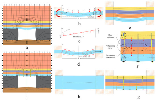
Figure 1.
Roof support principle. (a) Stress transfer under roof separation conditions; (b) Force analysis of rock beam; (c) Shear force of rock beam; (d) Secondary stress in beam; (e) Separation dividing into multi-layer rock beam; (f) Anchoring effect; (g) Anchoring combined with multi-layer rock beam; (h) Thick-layer anchored rock beam; (i) Stress transfer under roof separation elimination conditions.
A coordinate system was established with the leftmost part of the neutral axis of the rectangular cross-section rock beam as the coordinate origin, the direction spanning the tunnel as the X-axis, the longitudinal as the Y-axis, and the vertical as the Z-axis (Figure 1b,c). Let the upper load of the rock beam be q, the thickness be t, the span be s, and the elastic modulus be E. Let the moment of inertia of the beam per unit longitudinal thickness be I. Let the deflection, bending moment, bending stress and shear force at x be δx, Mx, σx, and Vx, respectively. The shear stress at point (x, z) is τxz.
Ignoring the subsidence and deflection of rock layers above the ribs caused by rib spalling, the roadway roof can be viewed as a rock beam clamped at both ends. Besides the clamping at the ribs, the beam is loaded only by horizontal stress and its self-weight stress (Figure 1b). The effectiveness of roof control is determined by the beam’s ability to support its own weight and transfer loads to the ribs and the beam’s ability to withstand secondary stresses within itself. Loads generate transverse shear force. Shear force is zero at the midspan transverse plane and increases toward the supports, proportional to the beam length (Figure 1c), promoting beam failure through sliding on planes in this direction. The bending deformation of the rock beam generates axial tension and compression (bending stresses) on either side of the neutral axis. These forces, in turn, generate bending moment couples within the beam (Figure 1d). Derived from statics:
The moment of inertia of the roof rock beam is proportional to the cube of its thickness. Deflection and bending stress are inversely proportional to the moment of inertia. Deflection, bending moment, and shear force are positively correlated with the span of the roof rock beam. Bending stress and shear stress are proportional to bending moment and shear force, respectively. The smaller the thickness and the larger the span of the roof rock beam, the worse its ability to support its own weight, transfer loads to the ribs, and withstand secondary stresses within the beam.
Coal roadways are situated in sedimentary rock sequences with well-developed bedding planes. Bedding planes are characterized by low tensile and low shear strength. Therefore, bedding planes constitute potential sliding surfaces and effectively segment the roof strata into a group of thin rock beams, allowing the immediate roof to sag under its own weight. After roadway excavation, the surrounding rock on either side of a bedding plane, due to differing deflections, creates expansive tensile force across the bedding plane, separating the surrounding rock into two rock beams. When a rock beam bends and subsides, its upper surface is compressed, and its lower surface is stretched. When rock beams on both sides of a bedding plane bend and subside together, shear slip occurs along the bedding plane. Under the combined action of tensile and shear failure, certain primary bedding planes in the roof strata develop into delaminations, segmenting the roof strata into multiple rock beams (Figure 1e). Without support, the deflection deformation of the lowest rock beam into the roadway space is unrestricted. Maximum bending stress occurs at the center of the lower surface of the beam. Rock mass under tension is highly prone to failure, compromising the integrity of the beam. This manifests as tensile failure in the center of the roadway roof, with progressive failure developing upward, potentially leading to roof collapse.
To protect the integrity of the roadway roof, the bearing capacity of the rock beam can only be improved by increasing its thickness and reducing its span. The function of rock bolts is to fix the rock mass within the anchored range into a thick anchored rock beam with sufficient bearing capacity. As shown in Figure 1f, after end anchorage of the bolt, pre-tensioning the bolt body increases the normal pressure on the rock beams on either side of the bedding plane, increasing friction and shear strength. For delamination to occur within the bolt-anchored zone, the high-strength bolt body itself must be stretched or sheared. That is, bolts enhance the tensile and shear strength of bedding planes within the anchored zone, inhibiting shear slip and opening development into delaminations, binding the surrounding rock within the anchored zone together to form a thick anchored rock beam (Figure 1g,h).
Forming a thick anchored rock beam above the roof through bolt anchoring eliminates roof delamination, promotes continuous horizontal stress in the roof, enhances the load-bearing capacity of the roof rock beam, reduces roof deflection, decreases secondary bending stresses, prevents tensile failure of surface rock mass, and ensures long-term safety and stability of the roadway space (Figure 1i).
2.2. Deformation and Failure Modes of Large-Span Roadway Roof
For large-span roadways with special requirements, roadway height restricts the achievable bolt length, while demands for ventilation and equipment installation increase the roadway span. The thickness of the anchored rock beam achievable with bolts cannot guarantee sufficient bearing capacity for the beam at such spans.
When the anchored layer thickness is limited, and the roadway span exceeds the self-supporting span of the anchored rock beam, the large-span roadway roof may deform and fail in the following modes.
2.2.1. Anchor Failure Within the Anchored Zone
Increased roadway span inevitably leads to increases in deflection, bending moment, shear force, bending stress, and shear stress in the anchored rock beam. The opening of bedding planes within the bolt-anchored zone generates tension in the bolts. This tension, combined with the clamping force provided by the bolt pre-tension, resists further opening of the bedding plane. When rock beams on both sides of a bedding plane within the anchored zone bend and subside together, relative movement shears the bolt body. When tension or shear exceeds the ultimate strength of the bolt, bolt rupture occurs, causing anchor failure. At this point, shear slip and opening along bedding planes within the anchored zone develop into delaminations, inducing increased roof deflection. Tensile failure occurs in the center of the roadway roof, progressively developing upward, leading to failure of the anchored rock beam and potentially roof collapse accidents.
2.2.2. Delamination Outside the Anchored Zone
When bolt strength is sufficient to resist the tensile-shear action on bedding planes within the anchored zone and maintain the relative integrity of the anchored roof rock beam, the deflection of the anchored rock beam in a large-span roadway becomes significantly greater than that of the rock layers outside the anchored zone. This induces the development of delaminations along bedding planes outside the anchored zone. Once delamination occurs outside the anchored zone, horizontal stress becomes discontinuous in the rock beam below this delamination. Consequently, the rock beam below the delamination transitions from a biaxial compression state to uniaxial compression only in the roadway excavation direction. The self-weight of this beam generates axial and vertical tensile stresses. During bending subsidence, tensile failure occurs in the center of the roadway roof, progressively developing upward. This subsequently induces anchor failure within the anchored zone, and potentially leads to the entire roof rock beam shearing off along the ribs.
3. Critical Time-Effective Roof Control Principle and Technology Based on Area Support
3.1. Critical Time-Effective Roof Control Principle Based on Area Support
After excavating a tailgate in the coal seam, during the stress adjustment process of the rock mass, the roof undergoes bending deformation toward the free face. When the bending deformation amounts between multiple rock layers are inconsistent, delamination occurs. In fact, roof collapse originates from delamination, which in turn stems from deformation. To control roof collapse, one must start by controlling roof deformation. Moreover, the larger the roadway span, the greater the roof bending deformation, the deeper the delamination development, and the more difficult it becomes to control. The delamination development depth in large-span tailgates often exceeds 3 m.
The core concept of delamination prevention and control for large-span roadway roofs is to achieve “area control” of the roof using chock-type supports or fully mechanized hydraulic supports. When a large area of the central roof of a large-span roadway is supported by chock supports or fully mechanized hydraulic supports, the subsidence of the roof in the “area-controlled” central region is restricted. The large-span roadway is effectively divided into two small-span roadways, i.e., “span reduction through area control” for large-span roadways. After “span reduction”, bending deformation occurs on either side of the “area-controlled” region. Compared to “point control”, roof subsidence is greatly reduced, and delamination development depth decreases to within 2 m. Combined with bolt support to form a critical anchored thickness, collapse instability is avoided, achieving critical temporary stability control during the roadway service period.
The concept of a continuous beam is proposed relative to a discontinuous beam, referring to a stable rock beam formed in the roof in both horizontal and vertical directions capable of transmitting continuous stress. Due to the large roadway span, roof bending deformation is positively correlated with span, with the maximum subsidence occurring at the roadway center, easily forming horizontal tensile stress. To achieve continuity in the span direction of a large-span roadway roof, the use of chock supports or fully mechanized hydraulic supports arranged parallel to the strike to support the central roof of the large-span roadway is proposed. This “area control for span reduction” treatment effectively divides the large-span roadway into two small-span roadways via the hydraulic support structure. Roof bending deformation will then exhibit a hump shape, roof subsidence is significantly reduced, tensile stress in the span direction is eliminated, and continuity of horizontal stress in the span direction is achieved. Achieving continuity in the vertical direction requires considering the support effect of bolts. The thickness of the anchored layer and the magnitude of bolt pre-tension play a decisive role in roof stability. When the anchored layer thickness and pre-tension force reach a certain level, delamination within the bolt length range, especially within the effective range of bolt pre-tension, will be effectively controlled. To achieve continuous stress deformation in the roof during the roadway service period, critical anchoring is performed by selecting an anchored layer thickness slightly greater than the delamination development depth under hydraulic support in the large-span roadway. Through the synergistic action of bolts and hydraulic supports, a continuous beam is formed in the large-span roadway roof, realizing critical time-effective roof control for large-span roadways.
3.2. Mechanical Analysis of Roof Deformation Under Area Support Based on Elastic Foundation Beam Model
Roadway excavation transforms the roof from a triaxial confining pressure state to a biaxial stress state. The ribs experience vertical stress concentration due to stress transfer, leading to roof bending deformation and rib spalling. Considering the engineering mechanical properties and deformation characteristics of coal roadway surrounding rock, the coal ribs are treated as an elastic foundation conforming to the Winkler foundation hypothesis [26]. Assuming the roof is intact and horizontal, it can be simplified as a beam for analysis. The roadway roof rock beam is viewed as a semi-infinite elastic foundation cantilever beam supported by the coal ribs. The settlement at any point on the rib surface is proportional to the pressure per unit area exerted by the roof rock beam at that point. The relationship between the vertical reaction force R in the rib and the roof deflection ω is:
where k is the Winkler foundation coefficient, related to the thickness and mechanical properties of the coal rib. k = E0b/h0, where b is the beam width; E0 is the compression modulus of the coal rib; and h0 is the thickness of the coal rib cushion layer.
Roadway excavation destroys the original stable state of the surrounding rock. After excavation, the roof rock beam loses the supporting stress from the coal body, while the overlying stress transfers to the ribs, breaking the original stress balance. The redistributed stress forces deformation of the surrounding rock, meaning the increment of overlying rock load is the fundamental cause of surrounding rock deformation. After roadway excavation, the overlying rock load increment curve above the roof rock beam is complex and difficult to describe and solve with a function. It is approximated as multi-segment straight lines for simplified calculation. Based on the principle of symmetry, the calculation model is established as shown in Figure 2. Let the roadway width be B, the overlying load increment on the roof be q1, and the maximum load increment on the ribs be q2, decreasing linearly with distance from the rib until it reduces to zero at x1. The roof rock beam has flexural rigidity EI (Elastic modulus E, Moment of inertia I), section stress σx, deflection ω, rotation θ, bending moment M, and shear force Q. The mathematical relationships between the internal forces and deflection of the rock beam are:
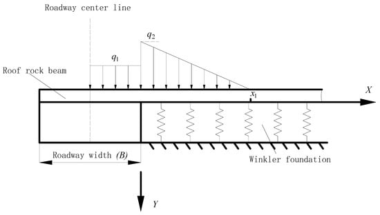
Figure 2.
Calculation model for large-span roadway.
From force equilibrium, the beam’s bending differential equation is:
Under hydraulic support area control, the roof in the controlled region is subjected to a given displacement. Assuming a support of width A is placed at the center of the roadway, the load increment outside the support area remains unchanged. Let the subsidence of the support under roof stress be S. Based on the principle of symmetry, the calculation model is established as shown in Figure 3. The mathematical relationships between internal forces and deflection of the rock beam still conform to Equation (8). From force equilibrium, the beam’s bending differential equation is:
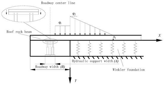
Figure 3.
Calculation model for large-span roadway under hydraulic support area control.
From symmetry: For the rock beam without hydraulic support, rotation and shear force are zero at the roadway centerline (). Deflection and shear force are zero at the point where the rib load increment reduces to zero (x = x1). According to Equation (8), the boundary conditions for this model can be expressed in terms of deflection and its derivatives as:
From symmetry: For the rock beam under hydraulic support, deflection is S and rotation is zero at the edge of the support (). Deflection and shear force are zero at the point where the rib load increment reduces to zero (x = x1). According to Equation (8), the boundary conditions for this model can be expressed in terms of deflection and its derivatives as:
Regardless of whether the roof rock beam is supported by hydraulic supports, at the point of load increment mutation (x = 0), its deflection, rotation, bending moment, and shear force are equal, expressed as:
Solving differential Equations (9) and (10): For x < 0, the solution is Equation (14). For , solve the fourth-order constant coefficient nonhomogeneous linear differential Equation (15). From , the characteristic Equation (16) has four characteristic roots: , . The general solution for the homogeneous differential equation corresponding to Equation (15) is shown in Equation (17), where . The particular solution for Equation (15) is , so the general solution for Equation (15) is .
The bending differential equation for the rock beam without hydraulic support is Equation (18). Combining Equations (11), (13), and (18) allows solving for the 8 unknowns A1~A4, B1~B4 in Equation (18). The bending differential equation for the rock beam under hydraulic support area control is Equation (19). Combining Equations (12), (13), and (19) allows solving for the 8 unknowns in Equation (19).
Taking the tailgate of Panel II513 at Huaibei Shuanglong Coal Mine as an example: width B = 8 m, height h0 = 3.2 m; field monitoring shows x1 = 8 m, overlying load increment on roof q1 = 7.5 × 10⁶ N/m, maximum load increment on ribs q2 = 1.5 × 10⁷ N/m; foundation coefficient k = 2.5 × 10⁸ N/m2; flexural rigidity of rock beam EI = 4 × 10⁹ N·m2; support width A = 1.5 m, and support subsidence S = 0.05 m.
Through calculation, the unknown parameters for Equation (18) are:
A1 = 0.0075, A2 = 2.3539 × 10⁻⁴, A3 = −0.0391, A4 = 0.146, B1 = −5.1029 × 10⁻⁴, B2 = −6.3678 × 10⁻⁴, B3 = 0.0865, B4 = −0.0016.
The unknown parameters for Equation (19) are:
A1 = 4.4953 × 10⁻⁴, A2 = −0.0032, A3 = −0.0021, A4 = 0.0541, B1 = −3.859 × 10⁻⁴, B2 = −0.0013, B3 = −0.0055, B4 = 0.0115.
Substituting the required parameters into Equations (18) and (19) can draw a comparison diagram of roof deflection between unsupported and area control support, as shown in Figure 4.
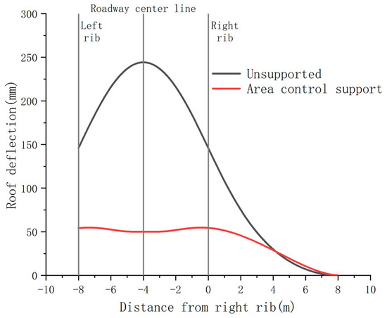
Figure 4.
Comparison of roof deflection.
Stress transmits continuously in the supported area of the roof. The support restricts the subsidence space, significantly reducing subsidence. Acting as a medium, the support directly transfers roof stress to the floor, functioning similarly to a coal pillar or backfill, effectively dividing the original large-span tailgate into two small-span roadways. The “span reduction” effect is evident. Reduced subsidence in the supported area divides the large-span tailgate roof subsidence into two smaller parts, presenting a “saddle-shaped” distribution.
3.3. Critical Time-Effective Roof Control Technology Based on Area Support
Fully mechanized hydraulic supports are arranged parallel to the strike to reinforce the roof of the large-span roadway, forming a reconstructed “steel rock mass” reinforcement in the middle of the large-span roadway, effectively creating two roadways with smaller spans. Using working face hydraulic supports to reinforce the roof during tailgate enlargement offers large support area, high working resistance, and good stability, and it requires no withdrawal. After the continuous miner advances, space for support adjustment is formed. Hydraulic supports are installed to support the roof, directly rotated into position for use as the working face’s main supports. This reduces installation and transportation links, lowers safety risks and labor intensity, and achieves a working face without single props (monolithic supports). The schematic diagram of integrated tailgate enlargement and support installation is shown in Figure 5.
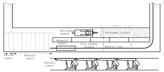
Figure 5.
Schematic diagram of integrated tailgate enlargement and support installation.
Construction sequence: Excavate tailgate → Assemble supports → Transport complete supports → Install hydraulic supports within the tailgate → Enlarge tailgate → Adjust strike-parallel hydraulic supports to face-advance direction → Supplementally install 2 face-advance hydraulic supports → Cycle through enlargement and installation until completion. Steps for integrated tailgate enlargement and support installation are shown in Figure 6, The alphabetical order in the figure is the sequence of steps.
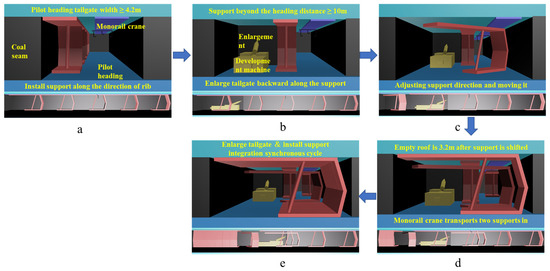
Figure 6.
Steps for integrated tailgate enlargement and support installation.
Before tailgate enlargement, under the original support scheme of the pilot heading, install a row of hydraulic supports parallel to the strike along the enlargement side to supplementally support the roof (Figure 6a). The initial setting pressure of the supports is ≥18 MPa. Maintain the hydraulic supports at least 10 m ahead of the enlargement face. Use a continuous miner to enlarge the tailgate continuously (Figure 6b). Keep a certain distance between the enlargement face and the support rotation/positioning operation point to ensure no mutual interference. Perform enlargement and installation in parallel (Figure 6c).
After the support is positioned, rotate the hydraulic supports one by one from the lower end of the tailgate into the face-advance direction. After rotating each first support, supplementally install two face-advance hydraulic supports between the rotated support and the next hydraulic support (Figure 6d). Repeat this cycle until the installation and positioning of all working face supports are completed (Figure 6e).
The core of the “1 + 2” integrated excavation and support method lies in using hydraulic supports arranged parallel to the strike to reinforce the large-span tailgate roof, achieving safe and efficient installation through parallel enlargement and support operations. The number “1” refers to installing 1 row of hydraulic supports parallel to the strike along the enlargement side within the tailgate to reinforce the roof, serving as the first support to be rotated and installed in each cycle; “2” refers to supplementally installing 2 hydraulic supports after the first support in each cycle is rotated into the face-advance direction.
4. Numerical Simulation of Critical Time-Effective Roof Control Based on Area Support
4.1. UDEC Numerical Simulation Model
Based on the actual geological conditions of the tailgate of Panel II513 at Huaibei Shuanglong Coal Mine, a UDEC model was designed with dimensions of 50 × 36.7 m. As shown in Figure 7, the model is divided into seven layers, from top to bottom: sandy mudstone, mudstone, coal (Seam 3/4), mudstone, coal (Seam 5), mudstone, and sandstone. Horizontal displacement is restricted on the left and right sides of the model, and vertical displacement is zero at the bottom. A vertical load of 7.5 MPa is applied to the upper boundary to simulate overburden load, with a lateral pressure coefficient of 1.0. The Mohr–Coulomb model is used. Mechanical parameters for strata and joints are listed in Table 1.
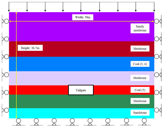
Figure 7.
Mechanical parameters of strata and joints.

Table 1.
Mechanical parameters of strata and joints.
4.2. Analysis of Simulation Results
Two support forms were simulated: conventional bolt-cable support and fully mechanized hydraulic support. Roof and rib bolt spacing was 0.8 m, bolt length was 2.5 m, hydraulic support width was 1.5 m, tailgate height was 3.2 m, and width was 8.0 m.
As shown in Figure 8, compared to conventional bolt-cable support, the vertical stress relief zone under area control support is significantly reduced, but the stress concentration in the ribs is more pronounced. Under the support action of hydraulic supports on the tailgate roof, continuous stress transfer occurs in the supported roof-floor region. Continuous stress transfer in the roof and the reduction of the stress relief zone promote continuous displacement between deep and shallow roof strata, eliminate roof delamination, and effectively maintain roof stability. Acting as a medium, the hydraulic supports directly transfer roof load to the floor, functioning similarly to a coal pillar or backfill, dividing the original large-span tailgate into two small-span roadways. The “span reduction” effect is evident. Continuous stress transfer in the supported area divides the stress relief zone into two smaller parts.
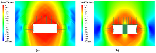
Figure 8.
Vertical stress distribution contour under different support forms: (a) conventional bolt-cable support; (b) area control support.
As shown in Figure 9, compared to conventional bolt-cable support, the horizontal stress relief zone under area control support is significantly reduced. When the roof is supported by hydraulic supports, vertical stress above the roof increases and transfers continuously, and horizontal stress also increases accordingly.
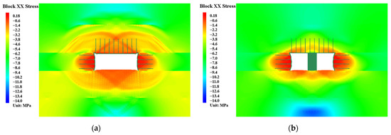
Figure 9.
Horizontal stress distribution contour under different support forms: (a) conventional bolt-cable support; (b) area control support.
As shown in Figure 10 and Figure 11, the maximum roof subsidence for conventional bolt-cable support and area control support are 256 mm and 113 mm, respectively. Area control reduces maximum roof subsidence by 55.9% compared to conventional support. Stress transmits continuously in the supported area of the roof. The hydraulic support structure restricts subsidence space, resulting in significantly less subsidence than in surrounding areas. Acting as a medium, the hydraulic supports directly transfer roof deformation to the floor, functioning similarly to a coal pillar or backfill, dividing the large-span tailgate into two small-span roadways. The “span reduction” effect is evident. Reduced subsidence in the supported area divides the large-span tailgate roof subsidence into two smaller parts, presenting a “cat-ear-shaped” distribution. The simulation results are very close to the theoretical calculation results.

Figure 10.
Vertical displacement distribution contour under different support forms: (a) conventional bolt-cable support; (b) area control support.
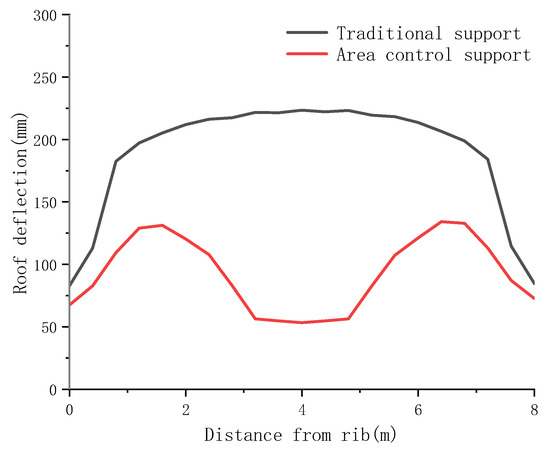
Figure 11.
Roof subsidence curve under different support forms.
As shown in Figure 12 and Figure 13, the maximum rib convergence for conventional bolt-cable support and hydraulic support area control are 299 mm and 371 mm, respectively. Hydraulic support area control increases maximum rib convergence by 27.4% compared to conventional support.

Figure 12.
Horizontal displacement distribution contour under different support forms: (a) conventional bolt-cable support; (b) area control support.
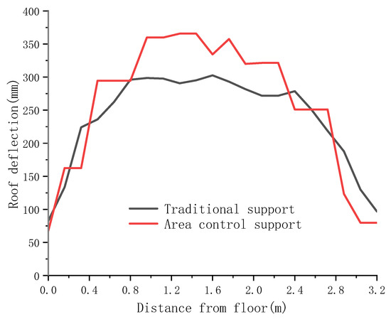
Figure 13.
Rib convergence curve under different support forms.
As shown in Figure 14, crack development in the roof under area control support is far lower than under conventional bolt-cable support. Crack development in the ribs under area control support is slightly higher than under conventional support.
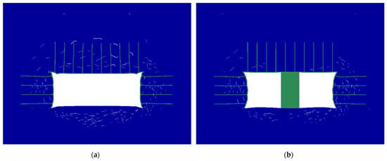
Figure 14.
Surrounding rock crack distribution under different support forms: (a) conventional bolt-cable support; (b) area control support.
5. Results and Discussion
5.1. Geological Conditions
Based on the mechanical analysis of roof deformation under area support using the elastic foundation beam model, this study investigated the influence of area support on roof stability. Taking the tailgate of Panel II513 at Huaibei Shuanglong Coal Mine as an example, the application of critical time-effective roof control technology based on area support was carried out. The tailgate of Panel II513 has an average depth of 310 m, a coal seam dip angle of 8~18° (average 13°), and an average coal thickness 3.2 m. The coal seam roof is sandy mudstone, with an average thickness 4.9 m. The coal seam floor is mudstone, with an average thickness 4.7 m.
5.2. Support Scheme
The tailgate of Panel II513 is 3.2 m high and 8 m wide. The construction scheme involves first excavating a 4.5 m wide pilot heading, then enlarging the pilot heading to 8 m. The cross-sectional view of the tailgate support design is presented in Figure 15.
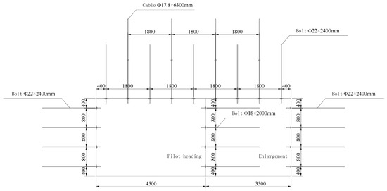
Figure 15.
Cross-sectional view of the tailgate support design.
Roof: Φ22 mm × 2400 mm high-strength longitudinal-ribless rebar bolts, spacing 1800 mm × 800 mm (row × column); Φ17.8 mm × 6300 mm cables, spacing 1800 mm × 800 mm.
Ribs: Φ22 mm × 2400 mm high-strength longitudinal-ribless rebar bolts, spacing 800 mm × 800 mm; Φ18 mm × 2000 mm fiberglass bolts on the enlargement side rib of the pilot heading, spacing 800 mm × 800 mm.
5.3. Control Effect and Discussion
As shown in Figure 16, the black curve shows monitoring results of maximum roof deformation in a tailgate of similar specifications in an adjacent panel without area control support. The red curve shows monitoring results of maximum roof deformation in the tailgate of Panel II513 under area control support.
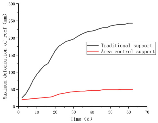
Figure 16.
Relationship curve between tailgate deformation and excavation time.
Under traditional support technology, the tailgate deformation rate is relatively fast in the initial construction stage, approximately 7 mm/d. Over time, the roof deformation rate slows significantly, eventually stabilizing, with a total roof deformation of about 250 mm.
Under the critical time-effective roof control technology based on area support, the deformation rate is significantly slower than under traditional support due to the support effect of hydraulic supports within the pilot heading. Over time, it eventually stabilizes, with a total roof deformation of about 50 mm. This is very close to the theoretical calculation result (Figure 4) and represents an 80% reduction compared to traditional support technology. Tailgate deformation is effectively controlled.
The allowable deformation value of the surrounding rock in coal roadways is not a fixed figure. For mining roadways with a short service life, under the premise of ensuring safe use and effective support, the total deformation of the roof within the range of 100 mm to 300 mm is a common empirical range. The critical time-effective roof control technology based on area support reduces the total deformation of the top plate from a qualified 250 mm to an excellent 50 mm.
In response to the issue that hydraulic supports are not applicable to large-span roadways other than the tailgate, chock-type supports can be used to replace hydraulic supports to achieve the critical aging control process for the surface support of large-span roadways.
6. Conclusions
- (1)
- The smaller the thickness and larger the span of the roof rock beam, the worse its ability to support its own weight, transfer loads to the ribs, and withstand secondary stresses within the beam. Deformation and failure modes of large-span roadway roofs include anchor failure within the anchored zone and delamination outside the anchored zone.
- (2)
- To prevent and control delamination in large-span roadway roofs, a critical time-effective roof control principle based on “span reduction through area control” achieved by supports was proposed. Mechanical analysis of roof deformation under area support was conducted based on the elastic foundation beam model. Substituting parameters from the tailgate of Panel II513 at Huaibei Shuanglong Coal Mine revealed that area control support can significantly reduce roof bending deformation. Consequently, the critical time-effective roof control technology using hydraulic supports for area support was proposed.
- (3)
- Based on the geological conditions of the tailgate of Panel II513 at Huaibei Shuanglong Coal Mine, support scheme parameters were designed. The total roof deformation under the critical time-effective roof control technology based on area support was approximately 50 mm, very close to the theoretical calculation result, representing an 80% reduction compared to traditional support technology. Tailgate deformation was effectively controlled. This demonstrates the significant importance of the proposed critical time-effective roof control principle based on area support for controlling the stability of large-span roadway surrounding rock.
Author Contributions
Funding acquisition, N.Z. and Z.X.; Investigation, J.W., N.Z., J.K., P.W., F.M. and G.C.; Methodology, J.W., N.Z., J.K., Z.X., P.W. and S.Q.; Supervision, N.Z., J.K. and D.P.; Writing—Original Draft, J.W., Z.X., P.W., F.M., G.C. and S.Q.; Writing—review and editing, N.Z., J.K. and D.P. All authors have read and agreed to the published version of the manuscript.
Funding
This research was funded by the National Key Research and Development Plan (2023YFC2907600), the National Natural Science Foundation of China (52034007), and the Young Elite Scientists Sponsorship Program by CAST (20230NRC001).
Institutional Review Board Statement
Not applicable.
Informed Consent Statement
Not applicable.
Data Availability Statement
The data presented in this study are available upon request from the corresponding author. The data are not publicly available due to containing information that could compromise the privacy of research participants.
Acknowledgments
We would also like to thank the anonymous reviewers for their valuable comments and suggestions that lead to a substantially improved manuscript.
Conflicts of Interest
The authors declare that this research received funding from the National Key Research and Development Plan, the National Natural Science Foundation of China, and the Young Elite Scientists Sponsorship Program by CAST. The funders were not involved in the study design, collection, analysis, interpretation of data, writing of the article, or the decision to submit it for publication.
References
- Wang, G.; Ren, H.; Zhao, G.; Zhang, D.; Wen, Z.; Meng, L.; Gong, S. Research and practice of intelligent coal mine technology systems in China. Int. J. Coal Sci. Technol. 2022, 9, 24. [Google Scholar] [CrossRef]
- Pu, L.; Liu, Y.; Cai, Y.; Sun, Z.; Zhou, X. Study on Active Support Parameters for Surrounding Rock with Ultra-Large Span Open-Off Cut in Thick Coal Seam. Appl. Sci. 2023, 13, 12804. [Google Scholar] [CrossRef]
- Wang, J.; Yue, P.; Wei, X. Failure Mechanism and Numerical Simulation of Surrounding Rock of Long-span Rectangular Roadway. Sci. Technol. Eng. 2023, 23, 991–997. [Google Scholar]
- Colwell, M.; Frith, R. Utilising the scientific method to demonstrate that slender beam/column behaviour is the dominant behavioural mechanism leading to roof/rib failure. Int. J. Min. Sci. Technol. 2021, 31, 867–887. [Google Scholar] [CrossRef]
- Brady, B.; Brown, E. Rock Mechanics for Underground Mining; Springer Science & Business Media: Berlin/Heidelberg, Germany, 2004. [Google Scholar]
- Bai, Q.; Tu, S. Failure analysis of a large span longwall drift under water-rich roofs and its control techniques. Eng. Fail. Anal. 2016, 67, 15–32. [Google Scholar] [CrossRef]
- Yin, J.; Fu, B.; Zhang, H. Failure Mechanism and Control Technology for a Large-Section Roadway under Weakly Cemented Formation Condition. Geofluids 2020, 1, 6669060. [Google Scholar] [CrossRef]
- Zhu, D.; Wu, Y.; Liu, Z.; Dong, X.; Yu, J. Failure mechanism and safety control strategy for laminated roof of wide-span roadway. Eng. Fail. Anal. 2020, 111, 104489. [Google Scholar] [CrossRef]
- Zheng, W.; Guo, Y.; Zhi, G.; Bao, X.; Sun, M.; Ren, R.; Duan, Z.; Gao, Z.; Wu, Q. Stability Analysis and Control Measures of Large-Span Open-Off Cut with Argillaceous Cemented Sandstone Layered Roof. Math. Probl. Eng. 2021, 1, 8744081. [Google Scholar] [CrossRef]
- Han, C.; Zhang, N.; Yang, H.; Zhao, Q.; Song, K. Discontinuous Deformation Characteristics of Deep Buried Roadway Roofs and Linkage Control of Thick Layer Cross-Boundary Anchorage: A Case Study. Energies 2023, 16, 2160. [Google Scholar] [CrossRef]
- Mark, C.; Barczak, T. Fundamentals of coal mine roof support. New Technology for Coal Mine Roof Support. In Proceedings of the NIOSH Open Industry Briefing; NIOSH IC: Washington, DC, USA, 2000; Volume 9453, pp. 23–42. [Google Scholar]
- Zhang, N.; Han, C.; Xie, Z. Theory of continuous beam control and high efficiency supporting technology in coal roadway. J. Min. Strat. Control Eng. 2019, 1, 48–55. [Google Scholar]
- Xie, Z.; Zhang, N.; Wei, Q.; Wang, J.; Sharifzadeh, M. Study on mechanical properties and application of a new flexible bolt. Appl. Sci. 2021, 11, 924. [Google Scholar] [CrossRef]
- Han, C.; Yuan, Y.; Ding, G.; Li, W.; Yang, H.; Han, G. The Active Roof Supporting Technique of a Double-Layer Flexible and Thick Anchorage for Deep Withdrawal Roadway under Strong Mining Disturbance. Appl. Sci. 2023, 13, 12656. [Google Scholar] [CrossRef]
- Li, Y.; Yang, R.; Fang, S.; Lin, H.; Lu, S.; Zhu, Y.; Wang, M. Failure analysis and control measures of deep roadway with composite roof: A case study. Int. J. Coal Sci. Technol. 2022, 9, 2. [Google Scholar] [CrossRef]
- Xie, S.; Gao, M.; Chen, D.; Sun, Y.; Pan, H.; Su, H.; Lan, S. Stability influence factors analysis and construction of a deep beam anchorage structure in roadway roof. J. Min. Sci. Technol. 2018, 28, 445–451. [Google Scholar]
- Yang, G. Cooperation technology of driving and supporting in large section coal roadway of deep mine and case analysis. Saf. Coal Min. 2022, 53, 89–97. [Google Scholar] [CrossRef]
- Li, Y.; Wang, Y.; Luo, G.; Zhang, Y. Mechanism and application of full-anchor cable support mechanism for direct roof with thick soft rock in mining roadway. J. Min. Sci. Technol. 2025, 10, 775–784. [Google Scholar] [CrossRef]
- Li, S.; Zhou, M.; Li, Z.; Zhao, J.; Liu, M. Research on Thick Layer Anchorage Control Technology of Deep High Ground Stress Roadway. Mod. Min. 2023, 39, 221–225. [Google Scholar]
- Wei, X.; Shahani, N.; Zheng, X.; Wang, J.; Wang, Y.; Chen, C.; Ren, Z. The retention and control technology for rock beams in the roof of the roadway: A case study. Processes 2023, 11, 1593. [Google Scholar] [CrossRef]
- Jin, Z.; Xu, Y.; Peng, T.; Gao, L.; Kong, D. Roof control technology of mining roadway under the influence of advanced supporting pressure. Adv. Civ. Eng. 2021, 1, 2049755. [Google Scholar] [CrossRef]
- Han, L.; Li, W.; Bjorhovde, R. Developments and advanced applications of concrete-filled steel tubular (CFST) structures: Members. J. Constr. Steel Res. 2014, 100, 211–228. [Google Scholar] [CrossRef]
- Ding, K.; Wang, L.; Tian, J.; Ren, B.; Jiang, C.; Wang, S. Design of a Highly Adaptable Advance Support for a Deep, Fully Mechanized Roadway and Analysis of Its Support Performance. Appl. Sci. 2022, 12, 12728. [Google Scholar] [CrossRef]
- Liu, X.; Hua, X.; Liang, Y.; Li, C. Quantitative Research on Roof Deformation and Temporary Support Stiffness in Deep-Mine Gob-Side Entry Retaining by Roof Cutting. Appl. Sci. 2024, 14, 6520. [Google Scholar] [CrossRef]
- Wang, X.; Lou, J.; Li, J.; Gao, F.; Yuan, G. Influence of rockbolt pretension on bolting behaviors by gravel bolting tests. J. Rock. Mech. Geotech. Eng. 2025, 1, 2. [Google Scholar] [CrossRef]
- Pan, H.; Li, S.; Zhang, T.; Lin, H. Composite key stratum module of Winkler foundation and its mechanical properties. J. Cent. South Univ. (Sci. Technol.) 2012, 43, 4050–4056. [Google Scholar]
Disclaimer/Publisher’s Note: The statements, opinions and data contained in all publications are solely those of the individual author(s) and contributor(s) and not of MDPI and/or the editor(s). MDPI and/or the editor(s) disclaim responsibility for any injury to people or property resulting from any ideas, methods, instructions or products referred to in the content. |
© 2025 by the authors. Licensee MDPI, Basel, Switzerland. This article is an open access article distributed under the terms and conditions of the Creative Commons Attribution (CC BY) license (https://creativecommons.org/licenses/by/4.0/).