Article

Performance Optimization of Grounding System for Multi-Voltage Electrical Installation

1
Centre for Electric Energy and High Voltage, CoE for Robotics and Sensing Technologies, Faculty of Artificial Intelligence and Engineering, Multimedia University, Cyberjaya 63100, Malaysia
2
Department of Computer Science, College of Computing and Information Technology, Shaqra University, Shaqra 11961, Saudi Arabia
*
Authors to whom correspondence should be addressed.
Appl. Sci. 2025, 15(15), 8600; https://doi.org/10.3390/app15158600
Submission received: 22 July 2025 / Revised: 31 July 2025 / Accepted: 1 August 2025 / Published: 2 August 2025

Abstract

Grounding systems are critical for ensuring electrical safety, fault current dissipation, and electromagnetic compatibility in power installations across different voltage levels. This research presents a comparative study on the optimization of grounding configurations for 400 V, 10 kV, and 35 kV electrical installations, focusing on key performance parameters such as grounding resistance, step and touch voltages, and fault current dissipation efficiency. The study employs computational simulations using the finite element method (FEM) alongside empirical field measurements to evaluate the influence of soil resistivity, electrode materials, and grounding configurations, including rod electrodes, grids, deep-driven rods, and hybrid grounding systems. Results indicate that soil resistivity significantly affects grounding efficiency, with deep-driven rods providing superior performance in high-resistivity conditions, while grounding grids demonstrate enhanced fault current dissipation in substations. The integration of conductive backfill materials, such as bentonite and conductive concrete, further reduces grounding resistance and enhances system reliability. This study provides engineering insights into optimizing grounding systems based on installation voltage levels, cost considerations, and compliance with IEEE Std 80-2013 and IEC 60364-5-54. The findings contribute to the development of more resilient and cost-effective grounding strategies for electrical installations.

1. Introduction

Grounding systems are essential for the safe operation of electrical installations of different voltage levels. Grounding systems primarily perform fault reduction, dissipate fault currents, limit electromagnetic interference, and afford protection from transient overvoltage [1]. The effects of grounding system performance are quite critical to electrical safety, system stability, and equipment lifespan. However, the process of design for a grounding system depends on certain reciprocal considerations regarding the characteristics of the soil, position of the electrodes, properties of the materials being used, and acceptance of international standards like IEEE Std 80-2013 [2] and IEC 60364-5-54 [3]. The performance of a grounding system hinges largely on its capability to maintain both low grounding resistance and low step and touch voltage hazards. Variations in soil resistivity, moisture content, and environmental factors are major factors hampering the efficiency of an optimal grounding design [4]. Furthermore, the selection of grounding electrodes, which can take the form of rod electrodes, grounding grids, deep-driven rods, or hybrid systems, profoundly affects the ability of a grounding system to dissipate fault currents. In this sense, medium- and high-voltage installations, such as 10 kV and 35 kV networks, could rise into hazardous conditions by the fault currents themselves, necessitating the implementation of advanced grounding methods to ensure safe dissipation of fault energy [5]. 
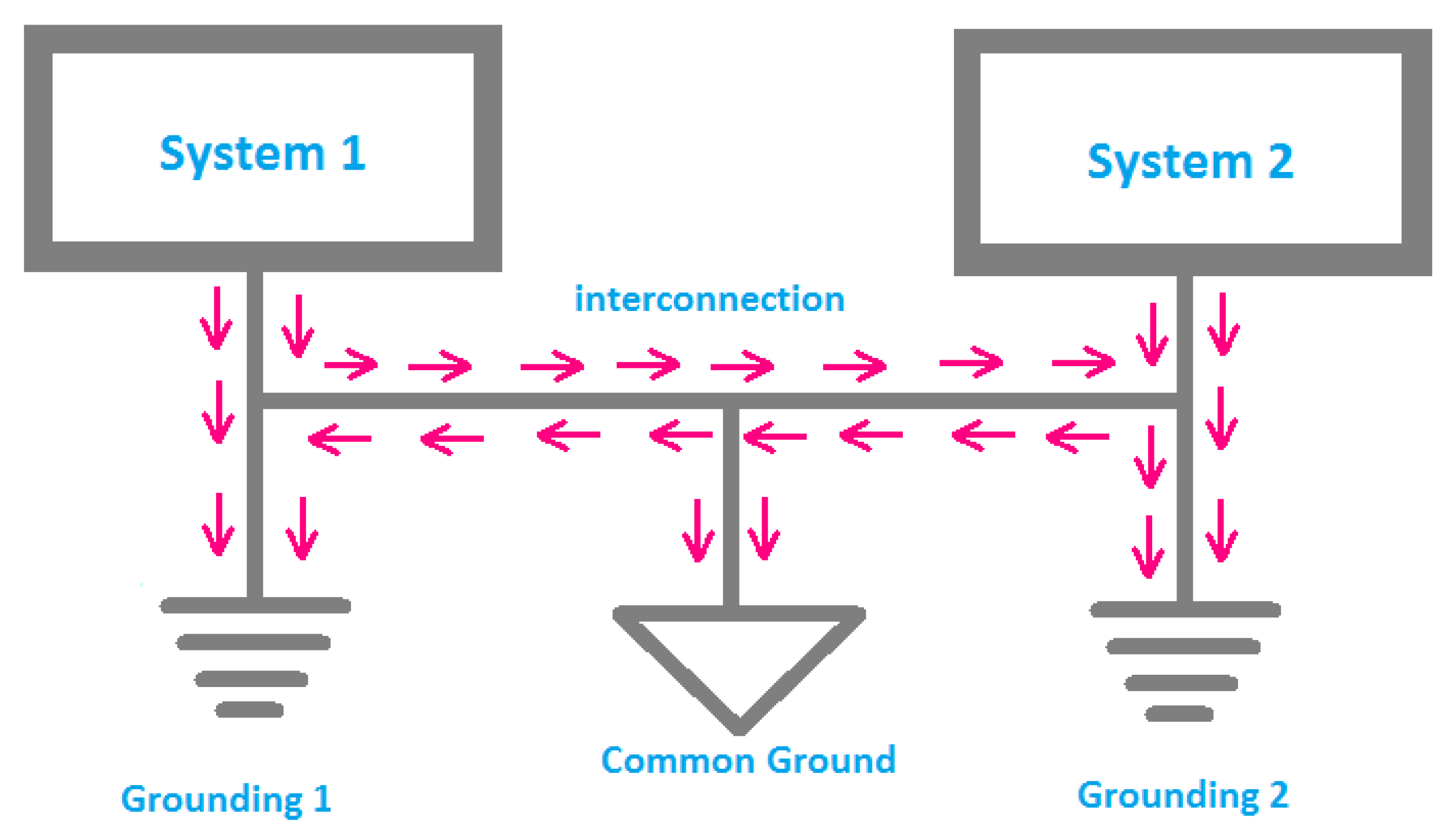
Figure 1 shows the traditional grounding system.
This study offers a comparative analysis of grounding systems for 400 V, 10 kV, and 35 kV electrical installations, including the range of configurations and soil conditions considered. The study employs computer simulations (finite element method—FEM), field measurements, and parametric analyses focusing on key aspects such as grounding resistance, rise in potential, step and touch voltages, and fault current dissipation efficiency [6]. In combining computer modeling with experimental backing, this work delivers best practices for cost-effective, efficiently designed grounding systems for varied voltage requirements. Another major intention is to assess the performance of the grounding systems with respect to different soil resistivities and changing environmental conditions with regard to the effectiveness of dissipating the fault action currents and safety voltages. The study will evaluate various grounding configurations with the assistance of rod electrodes, grounding grids, deep-driven rods, and hybrid systems to determine their efficiency in optimizing grounding designs for 400 V, 10 kV, and 35 kV installations. In order to confirm that respective grounding systems fall into compliance with adherence to international standards in step and touch voltage limits for guaranteed safety and operationally highest performance of the systems, target standards taken into consideration will be IEEE Std 80-2013 and IEC 60364-5-54 [3]. By addressing these objectives, this research aims to contribute to the development of more resilient, cost-effective, and technically optimized grounding strategies for modern electrical installations. The study not only enhances theoretical understanding but also provides practical guidelines for engineers, utility planners, and policymakers engaged in electrical grounding design.
The rest of the research is organized as follows: the principles of grounding systems in Section 2, followed by Section 3, Methodology, which combines FEM simulations and field measurements to assess grounding configurations across different soils. Section 4, Grounding Configurations and Optimization Techniques, compares various systems, like rod electrodes and grids, analyzing their efficiency. Section 5, Comparative Analysis of Grounding Performance, presents a comparison for 400 V, 10 kV, and 35 kV systems, focusing on fault current dissipation and safety voltages. Section 6, Discussion and Recommendations, addresses environmental factors and suggests further research on advanced materials and real-time monitoring. Finally, Section 7, Conclusion, emphasizes the need for tailored solutions and outlines areas for future research to improve safety and reliability, and suggests areas for future research to enhance safety and system reliability.

2. Principles of Grounding Systems

2.1. Purpose of Grounding Systems

Grounding systems in electrical installations are essential to ensure personnel safety, system reliability, and equipment protection. These systems serve multiple purposes, each with specific technical requirements to maintain a safe and functional electrical network.

2.1.1. Protection of Personnel from Electric Shock

The fundamental purpose of grounding is to provide a low-resistance path for fault currents to flow into the earth, thereby preventing electric shock hazards. This is particularly critical when faults such as short circuits or insulation breakdowns occur. In the absence of a good earthing system, fault currents could actually travel through a person, resulting in extreme injury or even death from electric shock. Touch voltage refers to the voltage difference between any two points that may be simultaneously contacted by a person and serves as an indicator of electric shock risk [7]. The touch voltage V t o u c h can be calculated as follows:
V t o u c h = I f a u l t × R g r o u n d
where I f a u l t is the fault current, R g r o u n d   is the resistance of the grounding system. To ensure personnel protection, the touch voltage must be kept below a threshold value, typically defined by safety standards like IEEE 80 or IEC 60364 [3].

2.1.2. Ensuring System Stability and Operational Reliability

Grounding systems stabilize the electrical system by placing certain values on an electrical reference point of the system voltage. Without proper references, voltages may vary widely up or down and lead to equipment malfunctions or, in worse cases, failures. Grounding ensures that during normal operations, all parts of the system maintain consistent potential with respect to the earth, further reducing overvoltage risk and aiding in ensuring that protective devices will operate reliably.
The increase in potential, V r i s e , at any point during a fault, depends both on the grounding system impedance as well as the fault current. The rise in potential across a connection at the site of a fault can be expressed as.
V r i s e = I f a u l t × Z g r o u n d
where Z g r o u n d   is the impedance of the grounding system. System stability is highly dependent on ensuring that the impedance is minimized, particularly in high-voltage systems like 10 kV and 35 kV, where high-fault currents can cause significant potential rises.

2.1.3. Reduction in Equipment Damage Due to Transient Overvoltages

Transient overvoltages originate from events such as lightning strikes or switching surges [8]. These overvoltages can cause insulation breakdown, leading to equipment damage. Grounding systems reduce this risk by offering a path for the transient currents to flow safely into the earth, thereby preventing equipment damage.
The voltage rise due to transient overvoltages can be quantified using the equation for the transient voltage surge,
V t r a n s i e n t = L · I t r a n s i e n t R g r o u n d
where I t r a n s i e n t is the transient current, L is the inductance of the system, and R g r o u n d is the grounding resistance. By providing a direct path for these surges to dissipate, grounding systems help protect sensitive equipment from such transient events.

2.2. Regulatory Standards and Guidelines

Grounding systems must comply with several international and national standards to ensure they are both effective and safe. These standards outline the design, construction, and maintenance of grounding systems to reduce hazards.

2.2.1. IEEE Std 80-2013: Guidelines for AC Substation Grounding

IEEE Std 80-2013 provides guidelines for grounding systems in AC substations, particularly focusing on safety from electric shock [9]. The standard includes detailed calculations for the safe touch voltage, step voltage, and ground potential rise (GPR) during fault conditions.
The GPR can be expressed as follows:
V G P R = I f a u l t 2 π × l n R s o i l r e l e c t r o d e
where I f a u l t is the fault current, R s o i l is the resistivity of the soil, and r e l e c t r o d e is the radius of the grounding electrode. This equation models the potential rise in the surrounding soil, which is crucial for designing grounding systems that minimize hazards to personnel.

2.2.2. Regulations for Earthing Arrangements

IEC 60364-5-54, which is concerned with earthing of low-voltage electrical installations, provides guidance on these aspects, such as minimum sizes of earthing conductors and other parameters such as impedance. This standard is formulated in order that earthing systems can adequately deal with fault currents without excessive rise in voltage or damage to any connected equipment. Table 1 shows the IEC 60364-5-54 Regulations for Earthing Arrangements.

2.2.3. National Electrical Code (NEC) Standards

The National Electrical Code (NEC), particularly Article 250, provides detailed requirements for grounding systems in the United States. It defines acceptable grounding electrode systems, the minimum size of grounding conductors, and the methods of connecting electrical systems to earth [10]. It requires the grounding system to possess adequate capacity to safely carry fault currents and reduce the risk of electric shock. Table 2 shows the National Electrical Code (NEC) Standards for Grounding in the USA.

2.3. Key Parameters Influencing Grounding Performance

Grounding performance is influenced by several parameters, including soil resistivity, electrode material, and system voltage levels. These parameters must be considered during the design phase to optimize the grounding system’s effectiveness.

2.3.1. Soil Resistivity and Moisture Content

Soil resistivity ρ s o i l is a critical factor in determining the performance of a grounding system. It varies with the moisture content, temperature, and soil composition. The resistivity of soil is typically measured in Ohm-meters (Ω·m). The total resistance of a grounding electrode in a given soil is given by the following:
R e l e c t r o d e = ρ s o i l 2 π · L ln D r e l e c t r o d e
where L is the length of the electrode, D is the distance from the electrode to the measurement point, and r e l e c t r o d e is the radius of the electrode. As the moisture content increases, soil resistivity decreases, improving the performance of the grounding system. In dry conditions, additional measures such as increasing the number of electrodes or using conductive materials may be required to ensure a low-impedance grounding path.

2.3.2. Electrode Material and Configuration

Electrode material impacts resistivity and corrosion resistance, influencing grounding performance. Copper is preferred for its low resistivity and high conductivity [12]. Electrode configuration (vertical, horizontal, or mesh) affects grounding resistance, with vertical rods performing better in high-resistivity soil due to greater earth contact.

2.3.3. System Voltage Level and Fault Current Magnitude

The voltage level and fault current magnitude significantly influence the design of grounding systems. Higher-voltage systems, such as 10 kV and 35 kV, necessitate grounding systems designed to manage higher fault currents. The fault current I f a u l t during a short circuit can be calculated using Ohm’s law:
I f a u l t = V s y s t e m Z t o t a l
where V s y s t e m is the system voltage, Z t o t a l is the total impedance of the fault path, including the impedance of the grounding system.
In high-fault-current systems, grounding electrodes must withstand large currents without damage. Proper design mitigates ground potential rise (GPR) to ensure safety, equipment protection, and system stability. Effective grounding requires careful planning of soil properties, electrode materials, and fault levels, adhering to international standards for optimal performance at various voltages (400 V, 10 kV, 35 kV).

3. Methodology

The optimization of grounding systems for different voltage levels (400 V, 10 kV, and 35 kV). It involves both computational modeling and experimental field measurements. The methodology integrates numerical simulations, measurement techniques, and analysis of various parameters that influence grounding performance.

3.1. Field Measurement Techniques

Field measurements are crucial to validate the results obtained through computational modeling and provide real-world data on grounding system performance.

3.1.1. Ground Resistance Testing Using the Wenner and Schlumberger Methods

To accurately measure the ground resistance, two primary methods are used: the Wenner method and the Schlumberger method. Both methods involve injecting a current into the ground and measuring the resulting potential difference.
Wenner Method: This method uses four equally spaced electrodes placed in a straight line. A current is injected into the outer electrodes, and the voltage is measured between the inner two electrodes. The ground resistance R g r o u n d is calculated using
R g r o u n d = 2 π α V I
where α is the spacing between the electrodes, V   is the voltage between the inner electrodes, and V is the injected current.
Schlumberger Method: In this method, the current electrodes are placed farther apart than the voltage electrodes. The resistance is calculated similarly, but the setup is more flexible for varying electrode spacings. The equation is as follows:
R g r o u n d = π ( M N ) I V
where M and N represent the positions of the current and voltage electrodes, respectively.

3.1.2. Step and Touch Voltage Analysis Using High-Precision Meters

Analysis of step and touch voltages is essential to assess the safety of the personnel under fault conditions [13,14]. Step voltage is the voltage between a person’s feet when standing on the ground, and touch voltage is the voltage between a person’s hand and the ground. Precision voltmeters and safety analyzers are employed to measure these voltages during fault simulations. The touch voltage V t o u c h and step voltage V s t e p can be verified for IEEE 80-2013 compliance [3], which recommends that these voltages should not exceed 430 V for 10 kV systems under fault conditions.

3.2. Soil Resistivity Analysis

Soil resistivity plays a significant role in the overall performance of grounding systems. Variations in soil resistivity due to seasonal changes or soil composition can significantly affect the effectiveness of a grounding system.

3.2.1. Measurement Techniques and Soil Layering Impact

Soil resistivity is measured using techniques such as the Wenner and Schlumberger methods [15]. In addition, the impact of soil layering is analyzed by considering variations in resistivity at different depths. The total ground resistance of a system depends on the resistivity of the individual layers, as shown by the following:
R t o t a l = 1 i = 1 n 1 R i
where R i   is the resistance of the individual soil layer i , n is the number of soil layers.

3.2.2. Seasonal Variations in Soil Resistivity

Soil resistivity varies with seasonal changes, particularly with moisture content. During wet seasons, soil resistivity decreases, which may improve the grounding system’s performance. In contrast, dry conditions can significantly increase resistivity, leading to a decrease in the system’s fault current dissipation capacity. These variations are taken into account during the design and testing phases.
Seasonal resistivity ρ s e a s o n can be approximated using a temperature and moisture content-dependent formula:
ρ s e a s o n = ρ d r y ( 1 + k · T + m · M )
where ρ d r y is the resistivity of dry soil, T is the temperature, M is the moisture content, and k and m are constants.

3.3. Evaluation Criteria

The performance of the grounding system is evaluated using several parameters that quantify the effectiveness of current dissipation, safety measures, and compliance with regulations.

3.3.1. Ground Resistance

Grounding resistance of a grounding device comprises three components: the resistance of the grounding body, the contact resistance between the grounding body’s surface and the soil, and the soil resistance as the current flows from the grounding body into the ground. The total ground resistance is a critical measure of the performance of the grounding system. Lower resistance enhances fault current dissipation efficiency and safety. The goal is to minimize R g r o u n d while ensuring the system meets all other design requirements. The efficiency of fault current dissipation is determined by the grounding system’s ability to absorb and safely direct fault currents into the earth. This efficiency is assessed by comparing the fault current dissipated by the system to the total fault current applied. Table 3 presents the evaluation criteria for grounding system optimization.
The dissipation efficiency η f a u l t can be calculated as follows:
η f a u l t = I d i s s i p a t e d I t o t a l × 100
where I d i s s i p a t e d   is the current dissipated into the ground, and I t o t a l is the total fault current.
These evaluation criteria offer a comprehensive approach to evaluating the optimization of grounding systems, from computational modeling to real-world measurements and performance criteria.

3.3.2. FEM Model Validation

To ensure the accuracy of the finite element method (FEM) simulations, a validation exercise was performed by comparing the simulated ground resistance values with those obtained from field measurements. The comparison was conducted across multiple grounding configurations using identical soil resistivity and geometric parameters. The results indicate a strong correlation between the simulated and measured values. The average absolute error observed was ±0.35 Ω, while the relative error remained below 7% for most cases. These deviations are considered acceptable within the typical range of variability expected in soil resistivity and measurement tolerances. The low error margins confirm that the FEM model accurately reflects the physical behavior of the grounding system and validates the appropriateness of the soil modeling and boundary conditions used in the simulations. This provides confidence in the use of the FEM results for optimizing design parameters and evaluating performance under various grounding scenarios.

4. Grounding Configurations and Optimization Techniques

4.1. Conventional Grounding Electrodes

Conventional earthing entails burying a copper plate or galvanized iron (GI) pipe within a pit layered alternately with salt and charcoal. This method requires regular water replenishment and periodic maintenance to ensure effective grounding. Conventional grounding electrodes include single rod electrodes and multiple rods, commonly used in electrical grounding systems [16]. The resistance of a single vertical rod electrode can be estimated using the following equation:
R = ρ 2 π L l n 4 L d
where R ground resistance (Ω), ρ = soil resistivity (Ω·m), L = length of the rod (m), d = diameter of the rod (m). As the length of the rod L increases, the resistance R decreases, leading to a more effective grounding electrode. A larger diameter d reduces the resistance, as a wider surface area allows more current to flow into the ground. The soil resistivity ρ has a direct impact on the resistance, with dry or rocky soil having higher resistivity, and moist, sandy, or clay-rich soil exhibiting lower resistivity.
In many practical applications, a single rod may not provide sufficient grounding, especially in areas with high soil resistivity [17]. To overcome this, multiple rods are used in parallel to reduce the overall grounding resistance. The resistance of the system with multiple rods depends on the number of rods nnn, their spacing, and the configuration in which they are arranged. For multiple rod configurations, the overall resistance R n is reduced as given by the following:
R n = R n K n
where n denotes the number of rods and K n is a spacing factor dependent on the configuration. The spacing factor K n can be estimated from empirical data or specialized charts that correlate the spacing of the rods and the configuration type with the resulting resistance. The closer the rods are spaced, the more effective the grounding system will be, as the total surface area for current dissipation increases. However, if rods are placed too close to one another, their individual effectiveness may be reduced due to mutual coupling effects, which can increase the total system resistance.
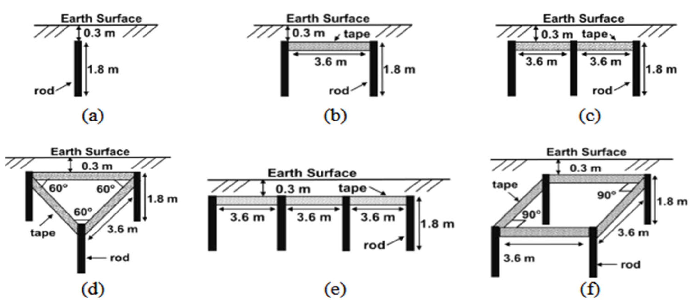
For example, if the rods are placed in a linear arrangement, the resistance will decrease more slowly as the number of rods increases. However, if the rods are arranged in a triangular or rectangular grid pattern, the resistance will decrease more efficiently, especially at larger spacings. Figure 2 displays the conventional grounding system arrangements [18].

4.2. Deep-Driven Rods and Vertical Electrodes

Deep-driven rods perform effectively in soils with high resistivity due to increased contact with lower-resistivity layers. 
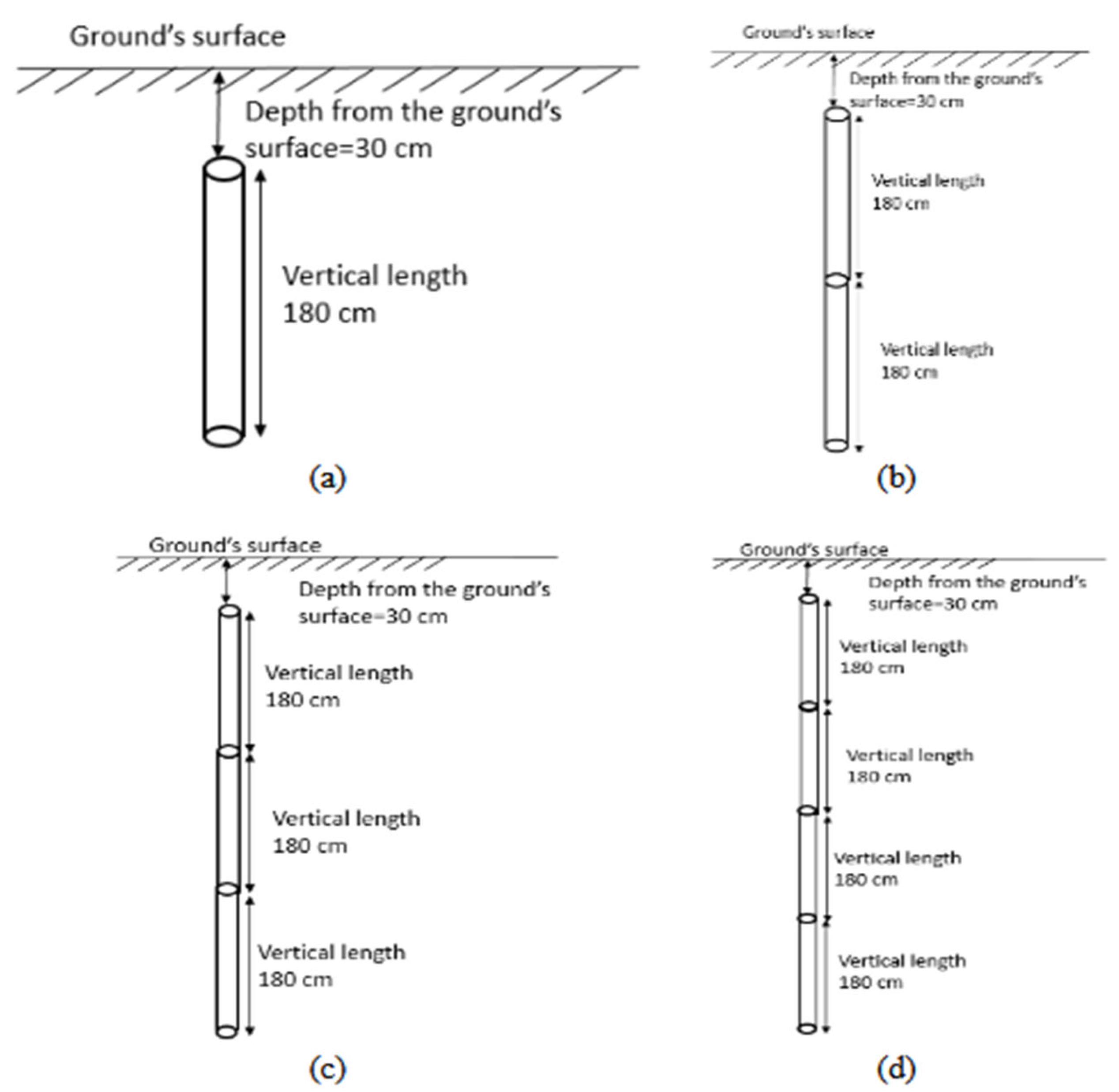
Figure 3 shows the ground electrodes used in vertical formulation [19]. This grounding system has been employed and tested in Cyberjaya, Malaysia. The reduction in resistance with increasing depth is as follows:
R d = ρ 2 π L l n 4 l d 1
Table 4 shows that as the rod length increases, the resistance decreases. In formation V1 (1.8 m rod), the resistance is highest at 35 Ω, indicating poor conductivity with the shorter rod. In formation V2 (3.6 m rod), resistance drops to 17 Ω, improving grounding efficiency. This trend continues in formation V3 (5.4 m rod) with a resistance of 15 Ω, and formation V4 (7.2 m rod) shows a further slight decrease to 13.5 Ω. While longer rods provide better grounding, the reduction in resistance diminishes as rod length increases, suggesting a point of diminishing returns. The error range was typically ±0.2 to ±0.5 Ω, depending on soil moisture at the time of testing.

4.3. Grounding Grids and Mesh Systems

Grounding grids improve fault current dissipation by providing multiple current paths. The grid resistance can be estimated as follows:
R g   = ρ 4 L 1 + K n
where K is a coefficient dependent on the grid layout.
For optimal design, IEEE Std 80-2013 suggests spacing electrodes based on the maximum step and touch voltage limits:
V s = I f R g A s
where V s = step voltage (V), I f = fault current (A), and A s = surface area of the grid (m2)

4.4. Use of Enhancing Materials (Bentonite, Conductive Concrete)

Enhancing materials like bentonite and conductive concrete reduces soil resistivity, improving grounding efficiency. The resistance of an electrode with an enhancement layer can be estimated using the following:
R e = ρ m 2 π L l n 4 L d + 2 t
where ρ m is the modified resistivity, and t is the thickness of the enhancement layer.
Table 5 shows the comparison of ground resistance with enhancing materials. The reduction in ground resistance was computed using the baseline resistance without enhancement material R 0 and the resistance with material R 1 via the following formula:
R e d u c t i o n   % = R 0 R 1 R 0 × 100

4.5. Hybrid Grounding Systems

Hybrid grounding combines vertical rods and horizontal conductors for improved performance [20]. The combined resistance is given by the following:
R h = R v R h R v + R h
where R v = resistance of vertical electrodes, and R h = resistance of horizontal electrodes.
Chemical electrodes can further reduce resistance by ionizing the surrounding soil, ensuring long-term stability. 
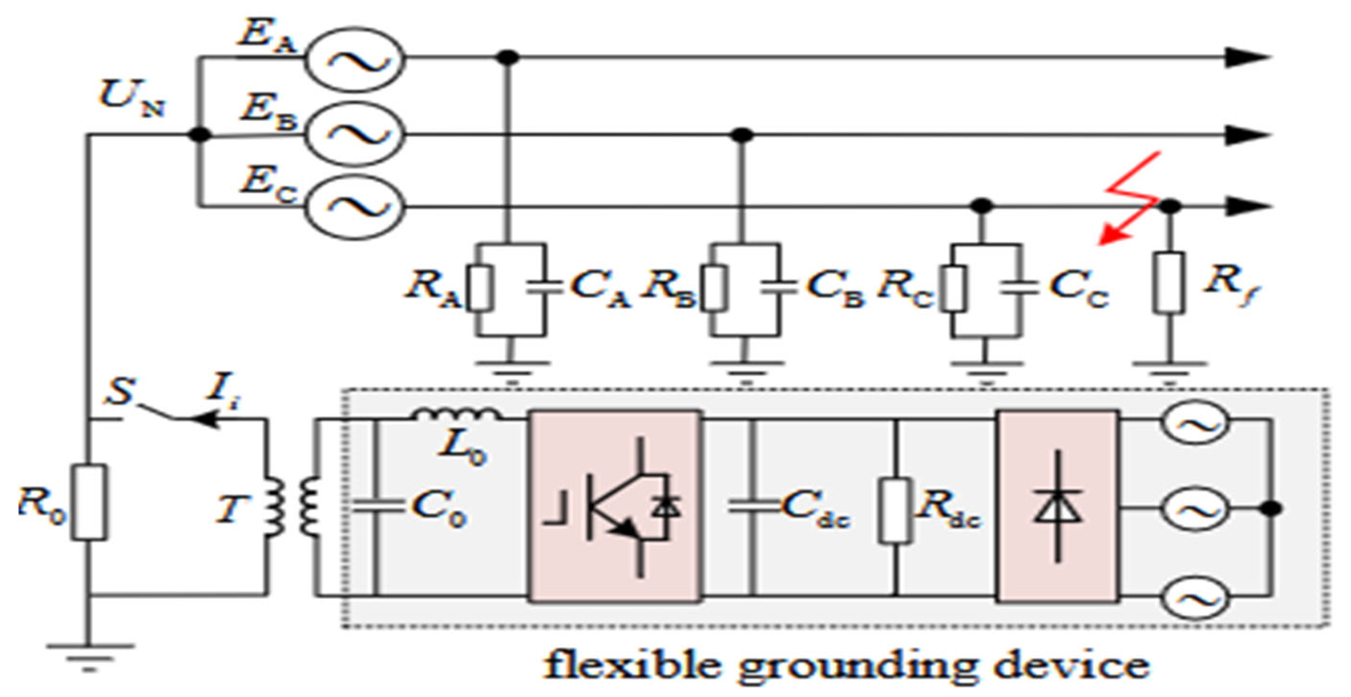
Figure 4 illustrates a hybrid grounding system layout.

4.6. Grounding Using Natural Conductors

In addition to conventional grounding methods involving rods, plates, and mesh systems, natural conductors such as metal water pipes, structural steel frameworks, and underground metallic fittings can serve as effective grounding paths. These elements, often already embedded in the infrastructure, provide an economical and practical means of achieving grounding, particularly in low-voltage or commercial installations. According to NEC Article 250.52(A) [3] and IEC 60364-5-54 (Clause 54.3), such conductors may be recognized as grounding electrodes, provided they meet specific criteria regarding their electrical continuity, corrosion resistance, and direct contact with the soil. For example, metal water pipes must be in contact with the earth for at least 3 m and must not be coated with insulating material that would inhibit conductivity. Similarly, structural steel must be securely bonded to the grounding system using approved mechanical or welded connections.
The use of natural conductors offers several advantages, including reduced material costs, simplified installation, especially in new buildings, and potential redundancy when used alongside conventional electrodes. However, there are limitations that must be considered. These include the risk of corrosion over time, potential discontinuities due to mechanical disassembly or use of insulating joints, and challenges in verifying the integrity of buried or inaccessible connections. Consequently, natural grounding conductors are best used to supplement, rather than replace, dedicated grounding electrodes, particularly in high-fault-current environments or critical systems requiring high reliability.
Regular testing and verification are essential to ensure the ongoing effectiveness of natural conductors in grounding applications. Their performance can vary widely depending on the type of material, the size and shape of the conductor, soil characteristics, and environmental exposure. When appropriately validated and maintained, natural conductors can play a valuable role in achieving safe and cost-effective grounding for electrical installations, particularly in residential, commercial, and light industrial settings.

5. Comparative Analysis of Grounding Performance

This section presents a comparative analysis of grounding performance in low-voltage (400 V), medium-voltage (10 kV), and high-voltage (35 kV) systems. Key factors such as fault current dissipation, grounding resistance, ground potential rise (GPR), step/touch voltage, and mitigation techniques are analyzed. Table 6 presents a comparison of grounding system configurations.

5.1. 400 V System (Low-Voltage) Grounding

In a commercial facility operating a 400 V three-phase system, a phase-to-ground fault occurs due to cable insulation failure, resulting in a fault current of 5 kA. The grounding system consists of a 2 m deep copper rod, and the surrounding soil has a resistivity of 100 Ω·m. The resistance of the grounding system can be calculated using Equation (14),
Substituting the given values, ρ = 100 Ω·m, L = 2 m, d = 16   m m into Equation (14),
= 100 2 π × 2 ln 4 × 2 0.016 = 3.2   Ω
The fault current dissipation can be determined by multiplying the fault current (5 kA) by the calculated resistance (3.2 Ω)
V G P R = I f R
From Equation (20),
V G P R = 5000   A × 3.2   Ω = 16,000   V
The resulting ground potential rise (GPR) of 16,000 V exceeds safe limits, posing a potential safety hazard. Therefore, to mitigate the risk, additional grounding rods are required to effectively reduce the GPR and ensure the safety of the system. To mitigate high ground potential rise (GPR), multiple grounding rods can be deployed in parallel, significantly reducing the overall resistance and enhancing fault current dissipation [21]. When n identical grounding rods are installed in parallel, the equivalent resistance R n e w is given by the following:
R n e w = R n
Table 7 shows the typical configurations and cost-effective solutions for a 400 V grounding system.

5.2. 10 kV System (Medium-Voltage) Grounding

Soil variations significantly affect ground potential rise (GPR) in 10 kV grounding systems is primarily governed by factors such as soil resistivity, moisture content, temperature, and composition. High soil resistivity, typically observed in arid or sandy soils, results in increased GPR due to limited current dissipation, potentially causing hazardous voltage gradients [22]. Conversely, low resistivity in moist or clay-rich soils enhances current flow, reducing GPR. Temperature variations impact resistivity, with higher temperatures generally increasing resistivity and raising GPR, while lower temperatures reduce resistivity and lower GPR. Furthermore, soil layer stratification with differing resistivities can cause uneven current distribution, further affecting GPR.
The 10 kV flexible grounding device topology is shown in Figure 5. E A , E B , and E C are the three-phase voltages, while R x and C x   ( x = A , B , C ) represent the network’s equivalent resistance and capacitance. T is the step-up transformer, and R 0 is the neutral grounding resistance. The device injects compensation current I i at the neutral point, with L 0 and C 0 serving as the filter inductance and capacitance. In a phase C ground fault, R f represents the transition resistance. Table 8 shows the impact of flexible grounding on fault current reduction. Upon a grounding fault, the flexible grounding device effectively suppresses fault current to zero and fully compensates residual current, achieving 100% transient arc extinguishment. Compared to ungrounded and small-resistance grounding modes, integrating a flexible grounding device with small-resistance grounding provides superior residual current suppression and higher arc extinction reliability.
Accurate soil resistivity measurements and seasonal variations are critical in the design of grounding systems to ensure compliance with safety standards and optimal system performance. Table 9 demonstrates the grounding strategies for medium-voltage (MV) installations.

5.3. 35 kV System (High-Voltage) Grounding

Grounding systems in high-voltage substations, particularly those rated at 35 kV, face significant challenges due to the high-fault currents and large potential gradients involved [24]. A primary concern is ensuring efficient fault current dissipation, which prevents dangerous step and touch voltages from affecting personnel and equipment. Inhomogeneous soil conditions, including varying resistivity and moisture content, further complicate the design and maintenance of grounding systems. Moreover, the expansive surface area of substations causes ground potential rise (GPR) to extend over a broad region, necessitating careful planning to ensure safe voltage levels throughout the substation. In many industries, high-resistance grounding is designed to ensure that the system’s capacitive charging current does not exceed the resistor current during a ground fault. This approach mitigates risks associated with ungrounded systems, such as overvoltages from inductive-capacitive resonance and intermittent ground faults [25]. In high-voltage mining environments, the employment of shielded cables—with higher capacitance than unshielded counterparts—adds complexity to grounding, requiring careful system design to maintain stability and safety. Table 10 shows the high-voltage substation grounding challenges for a 35 kV grounding system.
Table 11 presents a comparison of fault current dissipation across various voltage levels, highlighting the corresponding ground resistance, ground potential rise (GPR), and safety compliance based on Equation (21). For 400 V (LV), fault currents range from 5 to 10 kA with ground resistance between 3 and 5 Ω, resulting in a GPR of 15,000 to 25,000 V. This level is considered unsafe, necessitating additional rods for sufficient dissipation. For 10 kV (MV), fault currents range from 10 to 25 kA, with lower resistance (1 to 3 Ω) and a GPR of 15,000 to 30,000 V, still deemed unsafe and necessitating enhanced grids. For 35 kV (HV), fault currents of 15 to 40 kA and very low resistance (<1 Ω) lead to a GPR of 10,000 to 40,000 V, necessitating deep well grounding and counterpoise systems to ensure safety.
Higher-voltage systems require low-resistance grounding due to the significantly larger fault currents they must dissipate safely [26]. As the system voltage increases, the ground potential rise (GPR) escalates, necessitating more advanced grounding strategies to mitigate potential hazards. Mitigation techniques vary according to voltage levels: for 400 V systems, grounding can be achieved using simple rods combined with bentonite to enhance soil conductivity; for 10 kV networks, a more robust approach incorporating deep grounding rods and grounding grids is required; whereas for 35 kV transmission systems, an extensive grounding infrastructure involving counterpoise wires and deep wells is essential to effectively manage fault currents. Regardless of voltage, all grounding systems require step and touch voltage analyses to ensure compliance with IEEE 80 and NEC 250.56 standards, thereby guaranteeing personnel safety and system reliability. Table 12 shows the mitigation strategies for each grounding system.

5.4. Cost–Benefit Analysis of Different Grounding Configurations

High-performance systems—including multiple grounding electrodes, resistance grounding, or TN-S configurations—often require higher initial costs due to the need for additional materials, specialized components, and more complex installation processes [27]. Nevertheless, these systems provide higher levels of fault protection with lower ground potential rise (GPR) and better system safety. In the long term, these can translate into considerable cost savings due to the prevention of equipment damage and assurance of system operability. By stark contrast, cheaper alternatives, such as solid grounding or TN-C-S systems, tend to have lower initial costs, running to a satisfactory level in low-risk environments where the fault conditions are stable [28]. However, these alternatives fall short of providing adequate protection or performance in more demanding conditions. This tradeoff entails weighing system requirements, fault levels, and long-term maintenance costs very closely while choosing the grounding configuration to use for a specific installation. For high-risk or other situations where the environment is complex, spending for the higher performance systems offers promise for long-term gains, whereas cost-effective solutions may be admissible in less critical applications. Table 13 presents the cost–benefit analysis of various grounding configurations.

6. Discussion and Recommendations

6.1. Impact of Soil Resistivity Variations

Soil resistivity is a key factor influencing grounding system effectiveness. Since soil resistivity is affected by the moisture content, temperature variations, and soil composition, seasonal changes create a dramatic change in grounding system performance. For example, soil resistivity increases during dry periods, raising ground resistance, thus impairing fault current dissipation and augmenting the potential risk of equipment damage; some mitigation techniques to offset peak resistivity during dry weather include soil conditioning via chemical additives or conductive backfill installation. As we see it, these treatments work best in high-resistivity soil areas and thus make for a continuity of system reliability throughout the year. However, the effectiveness of soil treatments may be limited by unavoidable environmental factors, which may demand periodic maintenance for sustained effectiveness.
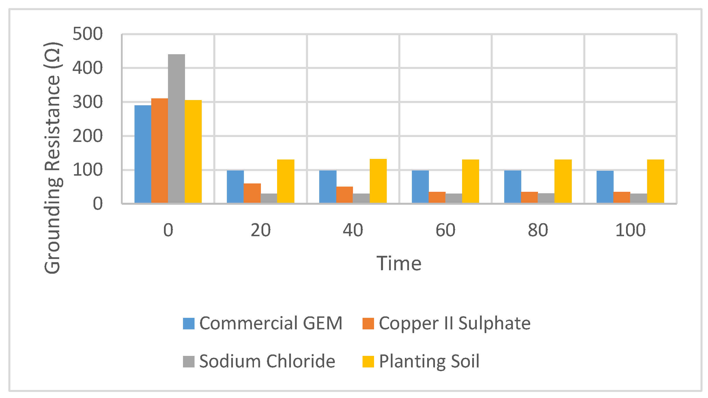
Grounding enhancement materials (GEM) such as Sodium Chloride and Copper II Sulphate provide significant reductions in earthing resistance. In Figure 6, Sodium Chloride shows the highest reduction of 96.45%), the commercially available GEM exhibits superior stability over time. The commercial GEM maintained a consistent earthing resistance with minimal fluctuation, making it more reliable for long-term use, especially in environments where moisture retention is crucial. Fluctuation of earthing resistance is shown in Table 14. Sodium Chloride, while effective initially, was found to dissolve in heavy rain, highlighting the need for periodic replenishment in tropical climates. Thus, for stable long-term performance, the commercial GEM is recommended.

6.2. Effectiveness of Different Electrode Materials

Electrode selection significantly impacts the performance and lifespan of grounding systems. Although the general consensus is that copper electrodes are the best due to their low resistance and high conductivity, guaranteed performance, and non-degradation, their high cost makes them uneconomical for large-scale installations. Galvanized steel electrodes, conversely, exhibit lower conductivity compared to copper. With their cost-effectiveness, adequate grounding performance is still experienced in many applications. Nevertheless, galvanized steel does corrode more easily as time progresses, particularly when buried in soils with high moisture, acid conditions, or both, hence additional reduction in longevity. Corrosion resistance and electrode lifespan are crucial factors that must be evaluated against local environmental conditions to ensure that the grounding system remains a viable prospect over time.

6.3. Safety Considerations and Compliance with Standards

Standards have to be followed through the IEEE and IEC for safety and performance. The standards state specifications with regard to ground resistance, electrode installation, and system performance that allow the proper execution of the grounding system in relation to the protective abilities of the personnel and equipment from an electrical fault. A periodic risk assessment and analysis for a fault scenario must be performed to find a justification for the potential fault conditions of a system high-fault currents or unexpected voltage surges [29]. Their ultimate aim shall be to indicate or expose the weaknesses in a certain grounding system, and draw conclusions for improvements required in order to obtain the safety of the grounding system. They are, therefore, requisite facilities to consider for safety against electrical hazards that mainly include, but are not restricted to, electric shocks and damage to equipment, while at the same time trying to ensure adequate system performance and reliability under all kinds of fault conditions [30].

6.4. Grounding Considerations in High-Altitude Mining Environments

Power supply security in high-altitude mining operations presents unique engineering challenges that directly affect grounding system performance. At high altitudes, lower atmospheric pressure, reduced air ionization, and dry or frozen soil conditions significantly decrease soil conductivity, resulting in higher ground resistance and elevated ground potential rise (GPR). These factors increase the risk of unsafe step and touch voltages, especially during fault or lightning events. Moreover, extreme temperature variations can accelerate corrosion in grounding conductors and compromise the long-term reliability of the system.
In such environments, conventional shallow-grounding techniques are often inadequate. Instead, deep-well electrodes, counterpoise systems, and soil conditioning compounds must be deployed to ensure adequate fault current dissipation. As highlighted in recent studies, the implementation of automated monitoring systems and remote control operations in high-altitude mines increases the reliance on stable and secure power systems, where grounding design becomes a foundational safety and reliability element [31]. The adaptation of grounding infrastructure to meet the demands of electrified and digitized mining systems is also emphasized in regional case studies [32].
Furthermore, grounding systems should be considered in tandem with insulation studies to offer a more comprehensive electrical safety strategy. Insulation degradation at high altitudes, combined with elevated GPR, can exacerbate insulation stress and increase the likelihood of equipment failure or personnel hazard. Therefore, integrating grounding system optimization with insulation coordination and surge protection schemes is essential for ensuring safe and reliable operations in high-altitude mining environments.

6.5. Recommendations for Optimal Grounding Strategies

Best practices for grounding design differ significantly across voltage levels; the specific needs of the installation dictate these differences. For low-voltage systems (e.g., 400 volts), normally, a simple solid grounding system or TN-C-S system is used; these systems assuredly protect in very much lower fault-risk environments. Medium- and high-voltage systems (e.g., 10 kV and above) utilize resistance grounding or multiple electrodes to cope with hefty fault currents and diminish ground potential rise (GPR), thus providing better protection and functional stability. Optimizing grounding systems in the present involves the loading of intelligent monitoring technologies-real-time resistance measure and automatic fault detection systems that bring in the smart, responsive, and high-efficiency maintenance system. Consequently, these technologies facilitate continuous monitoring and adjustment of grounding systems with minimal maintenance, which in turn boosts performance, permits lower maintenance costs, and makes them responsive. With all this, further protection can also be allotted to those grounding systems to optimize performance with due consideration to safety, reliability, and cost across different voltage levels and installation types.

6.6. Predictive Modeling of Long-Term Soil Resistivity Variations

Long-term variations in soil resistivity significantly affect the performance and reliability of grounding systems. These variations are primarily influenced by seasonal changes in temperature and moisture content, which alter the conductivity of the soil over time. To address this, a simple empirical predictive model is introduced to estimate the temporal evolution of soil resistivity, allowing for better planning and optimization of grounding system maintenance and performance forecasting. The model is expressed as follows:
ρ t = ρ 0 × ( 1 + α T + β M )
where the ρ t   is the predicted soil resistivity at time t , ρ 0 is the baseline soil resistivity under dry reference conditions, T   is the deviation in soil temperature from the baseline, M is the deviation in soil moisture content from the baseline, α and β are soil-type-specific coefficients that quantify the sensitivity of resistivity to temperature and moisture changes, respectively. This model allows for proactive adjustment of grounding system parameters based on environmental forecasts or sensor data. For example, in tropical climates, soil resistivity may increase significantly during dry seasons due to evaporation and reduced conductivity, while during the rainy season, increased moisture levels reduce resistivity and improve grounding effectiveness. By estimating future resistivity values, system designers can determine when to implement supplementary electrodes, chemical treatments, or system recalibrations.
In future work, this model can be enhanced using real-time monitoring tools (e.g., IoT-based soil sensors) and integrated into smart grounding system architectures for continuous adaptation to environmental conditions.

7. Conclusions

This study provides a comprehensive analysis of key aspects in optimizing grounding systems for 400 V, 10 kV, and 35 kV electrical installations, dealing with grounding resistance, fault current dissipation values, and safety voltages. The results reiterated the fact that soil resistivity plays a major role in the performance of grounding systems: at high resistivity, deep-driven rods were found to function better, while grounding grids were better at dissipating fault current in substations. Further reductions in grounding resistance and performance enhancements were observed with conductive backfill materials like bentonite and conductive concrete. The work discusses various configurations of grounding electrodes, such as rod electrodes, grids, deep-driven rods, and hybrid systems, also signifying that the best grounding system is contingent upon environmental conditions and the magnitude of the fault current. The grounding systems developed, in compliance with the respective international standards, IEEE Std 80-2013 and IEC 60364-5-54, provide the necessary protection against hazards associated with step and touch voltages, ensuring personnel safety and system reliability. This study contributes practical guidance for designing cost-effective, high-efficiency grounding systems across voltage levels that meet stringent safety and operational demands. By fusing computational simulation with field data, the study offers substantial perspectives on resilient grounding system designs that ensure enhanced safety and reliability in operations.
Future research should focus on the long-term performance, particularly in areas with extreme fluctuations of seasonal soil resistivity affecting the grounding systems. Understanding the mechanisms of electrode material degradation, especially those that occur in a corrosive environment, would lead to the enhancement of grounding system durability and lifespan. At the same time, through a dynamic view of soil resistivity and grounding system performance, diverse real-time monitoring tools, like those based on IoT sensors, may support more immersive and responsive designs of grounding. Further improvements may be expected from more sophisticated computational models that simulate elaborate fault and transient conditions, combined with larger-scale field data for the improvement of grounding system design for the standards of optimal performance. Lastly, assessing the economic performance of various grounding models in large-scale installations for a deeper understanding of the cost/benefit tradeoffs of optimizing grounding systems.

Author Contributions

Conceptualization, M.T.S.; methodology, M.T.S.; validation, M.T.S. and M.A.Q.; formal analysis, M.T.S., M.A.Q. and G.R.; investigation, M.T.S., M.A.Q. and M.S.H.; data curation, M.T.S., M.A.Q. and G.R.; writing—original draft, M.T.S.; writing—review and editing, M.T.S., M.S.H. and M.A.Q.; visualization, M.T.S. and M.A.Q.; supervision, G.R. All authors have read and agreed to the published version of the manuscript.

Funding

The funding for this project was provided by the Multimedia University under the post-doctoral research fellowship scheme, with the grant number MMUI/240028. Appreciation is also extended to the Research Management Center (RMC) of MMU for covering the article processing charges (APC).

Data Availability Statement

The original contributions presented in the study are included in the article. Further inquiries can be directed to the corresponding authors.

Acknowledgments

The authors gratefully acknowledge the support provided by the Multimedia University, Malaysia, for facilitating laboratory resources and technical assistance throughout this research. The authors would also like to thank the Deanship of Scientific Research at Shaqra University for supporting this work.

Conflicts of Interest

The authors declare no conflicts of interest.

References

  1. Bierals, G.P. Grounding and Bonding Photovoltaic and Energy Storage Systems; CRC Press: Boca Raton, FL, USA, 2025. [Google Scholar]
  2. IEEE Guide for Safety in AC Substation Grounding; IEEE: New York, NY, USA, 2015; pp. 1–226.
  3. IEC 60364-5-54; Installations—Part, Low-Voltage Electrical. Part 5–54: Selection and Erection of Electrical Equipment-Earthing Arrangements and Protective Conductors. IEC: Geneva, Switzerland, 2011.
  4. Malanda, S.C.; Davidson, I.E.; Singh, E.; Buraimoh, E. Analysis of soil resistivity and its impact on grounding systems design. In Proceedings of the 2018 IEEE PES/IAS Power Africa, Cape Town, South Africa, 28–29 June 2018; IEEE: New York, NY, USA; pp. 324–329. [Google Scholar]
  5. Bindi, M.; Piccirilli, M.C.; Luchetta, A.; Grasso, F. A comprehensive review of fault diagnosis and prognosis techniques in high voltage and medium voltage electrical power lines. Energies 2023, 16, 7317. [Google Scholar] [CrossRef]
  6. Marinkovic, D.; Zehn, M. Survey of finite element method-based real-time simulations. Appl. Sci. 2019, 9, 2775. [Google Scholar] [CrossRef]
  7. Kostić, V.I.; Raičević, N.B. An alternative approach for touch and step voltages measurement in high-voltage substations. Electr. Power Syst. Res. 2016, 130, 59–66. [Google Scholar] [CrossRef]
  8. Zalhaf, A.S.; Zhao, E.; Han, Y.; Yang, P.; Almaliki, A.H.; Aly, R.M. Evaluation of the transient overvoltages of HVDC transmission lines caused by lightning strikes. Energies 2022, 15, 1452. [Google Scholar] [CrossRef]
  9. Farooq, H.; Ali, W.; Iqbal, H.; Rasool, A.; Sajjad, I.A.; Noon, A.A. Evaluation of the Safety Performance of a 500-kV AC Substation Grounding Using IEEE Standard 80-2013. Electrica 2021, 21, 225+. [Google Scholar] [CrossRef]
  10. Kavimandan, M.D. Electrical Grounding Impedance and Gap (s) in IEEE STD. 80, NESC®, or NEC®—A Project Case. In Proceedings of the 2024 IEEE/PES Transmission and Distribution Conference and Exposition (T&D), Anaheim, CA, USA, 6–9 May 2024; IEEE: New York, NY, USA; pp. 1–4. [Google Scholar]
  11. Sergent, J.S.; Coach, C.D.; Roux, R.J. National Electrical Code Handbook; NFPA: Quincy, MA, USA, 2011. [Google Scholar]
  12. Zhang, C.; Liao, Y.; Gao, X.; Zhao, J.; Yuan, Y.; Liao, R. Research advances of soil corrosion of grounding grids. Micromachines 2021, 12, 513. [Google Scholar] [CrossRef]
  13. dos Santos, G.; Martins, F.G.; Sass, F.; Sotelo, G.G.; Morandi, A.; Grilli, F. A 3-D finite-element method approach for analyzing different short circuit types in a saturated iron core fault current limiter. IEEE Trans. Appl. Supercond. 2022, 32, 1–13. [Google Scholar] [CrossRef]
  14. Hsu, S.H.; Tzu, F.M.; Chang, W.H.; Chen, Y.D. Assessing high-voltage shore connection safety: An in-depth study of grounding practices in shore power systems. Energies 2024, 17, 1373. [Google Scholar] [CrossRef]
  15. Allred, B.J.; Groom, D.; Ehsani, M.R.; Daniels, J.J. Resistivity methods. In Handbook of Agricultural Geophysics; CRC Press: Boca Raton, FL, USA, 2008; pp. 85–108. [Google Scholar]
  16. Clark, D.; Mousa, S.; Harid, N.; Griffiths, H.; Haddad, A. Lightning current performance of conventional and enhanced rod ground electrodes. IEEE Trans. Electromagn. Compat. 2021, 63, 1179–1188. [Google Scholar] [CrossRef]
  17. Kherif, O.; Robson, S.; Haddad, A.; Thorpe, D. On the optimization of grounding design of rods covered by low resistivity materials. In Proceedings of the 2022 57th International Universities Power Engineering Conference (UPEC), Istanbul, Turkey, 30 August 2022; IEEE: New York, NY, USA; pp. 1–6. [Google Scholar]
  18. Muhammad, U.; Zaid, H.; Ahmad, N.N.; Nor, N.M.; Aman, F. Evaluation of steady-state ground resistance by field measurement and CDEGS computation. Bull. Electr. Eng. Inform. 2024, 13, 3033–3042. [Google Scholar] [CrossRef]
  19. Shamsul, S.A.; Muhammad, U.; Aman, F.; Nor, N.M.; Osman, M. Comparing horizontal versus vertical arrangement on the ground resistance values. Bull. Electr. Eng. Inform. 2024, 13, 3841–3849. [Google Scholar] [CrossRef]
  20. Lin, C.; Sen, W.; Zhi, Z.; Jing, W.; Bo, Z.; Weidong, S. Design of grounding system for wind-photovoltaic-energy storage Hybrid power station. In Proceedings of the 2014 ICHVE International Conference on High Voltage Engineering and Application, Poznań, Poland, 8–11 September 2014; IEEE: New York, NY, USA; pp. 1–5. [Google Scholar]
  21. Amadi, H.N. Design of grounding system for AC substations with critical consideration of the mesh, touch and step potentials. Eur. J. Eng. Technol. 2017, 5, 44–57. [Google Scholar]
  22. Rasheed, M.W.; Tang, J.; Sarwar, A.; Shah, S.; Saddique, N.; Khan, M.U.; Nawaz, S.; Shamshiri, R.R.; Aziz, M.; Sultan, M. Soil moisture measuring techniques and factors affecting the moisture dynamics: A comprehensive review. Sustainability 2022, 14, 11538. [Google Scholar] [CrossRef]
  23. Liu, M.; Zhang, C.; Liu, K. Simulation and experiment analysis of 10 kV flexible grounding device. Information 2021, 12, 384. [Google Scholar] [CrossRef]
  24. Shern, S.J.; Sarker, M.T.; Haram, M.H.S.M.; Ramasamy, G.; Thiagarajah, S.P.; Al Farid, F. Artificial intelligence optimization for user prediction and efficient energy distribution in electric vehicle smart charging systems. Energies 2024, 17, 5772. [Google Scholar] [CrossRef]
  25. Paul, D. High-resistance grounded power system. IEEE Trans. Ind. Appl. 2015, 51, 5261–5269. [Google Scholar] [CrossRef]
  26. Pourmirasghariyan, M.; Zarei, S.F.; Hamzeh, M. DC-system grounding: Existing strategies, performance analysis, functional characteristics, technical challenges, and selection criteria-a review. Electr. Power Syst. Res. 2022, 206, 107769. [Google Scholar] [CrossRef]
  27. Sarker, M.T.; Al Qwaid, M.; Shern, S.J.; Ramasamy, G. AI-Driven Optimization Framework for Smart EV Charging Systems Integrated with Solar PV and BESS in High-Density Residential Environments. World Electr. Veh. J. 2025, 16, 385. [Google Scholar] [CrossRef]
  28. Barrett, M. Using Virtual Reality Modelling to Enhance Electrical Safety and Design in the Built Environment. Ph.D. Thesis, Technological University Dublin, Dublin, Ireland, 2012. [Google Scholar]
  29. Sarker, M.T.; Rahman, M.A.; Rahman, T.; Sarker, A.; Sarker, V.K.; Mahmud, Z.H. GSM & microcontroller based three phase fault analysis system. Int. J. Adv. Res. Technol. 2017, 6, 1–8. [Google Scholar]
  30. Rahman, M.A.; Khan, M.; Sarker, M.T.; Mahmood, Z.H. Design, Inspection and Implementation of Solar PV Driven Smart & Automated Irrigation Systems. Int. J. Sci. Eng. Invent. 2016, 2, 18–22. [Google Scholar]
  31. Radebe, N.; Chipangamate, N. Mining industry risks, and future critical minerals and metals supply chain resilience in emerging markets. Resour. Policy 2024, 91, 104887. [Google Scholar] [CrossRef]
  32. Koul, P. Advancements in underground mining equipment design: Safety, finite element analysis, and structural innovations. Synerg. Int. J. Multidiscip. Stud. 2025, 2, 24–43. [Google Scholar] [CrossRef]
Figure 1. Traditional grounding system.
Applsci 15 08600 g001
Figure 2. Conventional grounding system arrangements; (a) single road, (b) 2-parallel rods, (c) 3-parallel rods, (d) triangular rod grid, (e) 4-parallel rods, and (f) rectangular rod grid.
Applsci 15 08600 g002
Figure 3. Ground electrodes used; (a) formation V1, (b) formation V2, (c) formation V3, and (d) formation V4.
Applsci 15 08600 g003
Figure 4. Hybrid grounding system.
Applsci 15 08600 g004
Figure 5. The 10 kV flexible grounding device topology [23].
Applsci 15 08600 g005
Figure 6. Earthing resistance of various GEM against time.
Applsci 15 08600 g006
Table 1. IEC 60364-5-54 Regulations for Earthing Arrangements [2].
ClauseRegulation AspectDescription
54.1General RequirementsSpecifies the need for protective earthing and equipotential bonding to ensure electrical safety.
54.2Types of Earthing SystemsDefines TN, TT, and IT earthing systems and their respective grounding methods.
54.3Earth ElectrodesSpecifies types (rod, plate, strip, foundation earth) and installation guidelines.
54.4Protective ConductorsDefines cross-sectional area requirements and materials (copper, aluminum, galvanized steel).
54.5Equipotential BondingRequires bonding of exposed conductive parts and extraneous conductive parts to minimize touch voltages.
54.6Earthing ResistanceEstablishes limits for ground resistance to ensure safe fault current dissipation.
54.7Connection MethodsSpecifies bolted, welded, or exothermic welding for secure electrical continuity.
54.8Lightning Protection IntegrationCoordination with IEC 62305 for integrating grounding systems with lightning protection.
54.9Testing and VerificationMandates periodic ground resistance testing and documentation.
Table 2. National Electrical Code (NEC) Standards for Grounding in the USA [11].
NEC ArticleRegulation AspectDescription
Article 90IntroductionDefines the scope, purpose, and application of NEC grounding requirements.
Article 100DefinitionsProvides key definitions for grounding, bonding, and related electrical terms.
Article 110.26Working Space RequirementsSpecifies clearances for electrical equipment to ensure safe maintenance.
Article 250Grounding and BondingComprehensive guidelines for grounding and bonding of electrical systems.
250.4General RequirementsEstablishes principles for effective fault current path and protection against electric shock.
250.52Grounding ElectrodesLists acceptable grounding electrode types (e.g., ground rods, water pipes, concrete-encased electrodes).
250.56Resistance of Grounding ElectrodesSpecifies that the ground electrode system should have a resistance of 25 ohms or less.
250.66Sizing of Grounding Electrode ConductorsDefines the minimum size of conductors based on service entrance conductor size.
250.90-250.96Bonding RequirementsMandates bonding of metallic parts to eliminate potential differences.
250.102Grounding Conductor SizingSpecifies minimum conductor sizes for grounding based on system capacity.
250.104Bonding of Piping and Structural MetalRequires bonding of metal water piping and structural steel to the grounding system.
250.186High-Voltage SystemsOutlines special grounding rules for systems above 1 kV, including industrial applications.
Article 690Solar PV System GroundingProvides grounding rules for photovoltaic systems to prevent electrical hazards.
Table 3. Evaluation criteria for grounding system optimization.
ParameterUnitCalculation MethodStandard/Limit
Ground ResistanceOhmsCalculated from Wenner or Schlumberger methodMinimum value as per NEC
Step VoltageVoltsMeasured during fault condition≤430 V (IEEE 80-2013)
Touch VoltageVoltsMeasured during fault condition≤430 V (IEEE 80-2013)
Fault Current Dissipation EfficiencyPercentage (%) η f a u l t = I d i s s i p a t e d I t o t a l × 100 Maximized for safety and reliability
Table 4. Effect of rod depth on resistance.
Formulation Rod Length (m) Measured Resistance (Ω) Measurement Error (±Ω)
a1.835.0±0.5
b3.617.0±0.4
c5.415.0±0.4
d7.213.5±0.3
Table 5. Comparison of ground resistance with enhancing materials.
Enhancement MaterialReduction in Resistance (%)Voltage Reduction (%)Current Withstand Increase (%)
Bentonite40%30%35%
Conductive Concrete60%45%50%
Table 6. Comparison of grounding system configurations.
Parameter 400 V System (LV) 10 kV System (MV) 35 kV System (HV)
ApplicationResidential, commercial, small-scale industriesIndustrial distribution, substations, EV chargingTransmission substations, large-scale power distribution
Fault Current (kA)2–1010–2515–40
Grounding ElectrodeSingle rod or gridDeep-driven rods and gridExtensive grounding grid + counterpoise
Resistance (R)1–5 Ω0.5–3 Ω<1 Ω
Ground Potential Rise (GPR) (V)200–20002000–50005000–10,000
Step Voltage (V)<5001000–20002000–4000
Touch Voltage (V)<250500–15001500–3000
Mitigation MeasuresRod extension, equipotential bondingAdditional rods, bentonite, grounding meshLarge grounding grids, counterpoise, deep wells
Table 7. Typical configurations and cost-effective solutions for a 400 V grounding system.
ConfigurationDescriptionCost-Effective Solutions
Solid GroundingNeutral point directly connected to the ground, providing a low-impedance path.Simple, low-cost solution; suitable for smaller systems where fault currents are manageable.
Resistance GroundingA resistor is used between neutral and ground to limit fault current.Low-cost resistors can be used; reduces fault current and minimizes the risk of equipment damage.
TN-S SystemSeparate neutral and ground conductors, neutral directly grounded at the source.Common in residential/commercial installations; cost-effective, especially for lower-risk fault scenarios.
TN-C-S SystemCombined neutral and ground conductor used for part of the system and separate for the rest.Economical for residential and commercial installations, as it reduces the need for multiple conductors.
Multiple Grounding ElectrodesUse of multiple ground rods or plates to increase surface area for fault current dissipation.Cost-effective for larger systems; uses affordable electrodes to reduce resistance and improve fault current flow.
Equipotential BondingBonding all metallic parts (e.g., pipes, structures) to the grounding system.Inexpensive and ensures that all conductive parts are at the same potential, reducing shock hazards.
Earthing ConductorsUse of low-resistance, copper or aluminum conductors for connecting to the ground.Use aluminum conductors instead of copper for cost savings while maintaining safety and efficiency.
Use of Grounding PlatesGrounding plates (e.g., copper or galvanized steel) buried in the ground.A cost-effective solution in areas with high soil resistivity; provides good fault current dissipation.
Soil ConditioningChemical additives or conductive backfill materials to improve soil conductivity.Inexpensive chemical treatments or backfill solutions can lower soil resistivity, improving grounding performance.
Table 8. Impact of flexible grounding on fault current reduction.
Fault TypeTransition Resistance Earthing TypeFault Current Device Earlier UseFault Current Device Later Use
Metallic Earthing0Ungrounded86.550.87
Small-Resistance Earthing18.410.35
Low-Resistance Earthing 10 2 Ungrounded78.790.33
Small-Resistance Earthing2.810.24
High-Resistance Earthing 10 3 Ungrounded8.510.28
Small-Resistance Earthing1.390.12
Table 9. Grounding strategies for medium-voltage (MV) installations.
Grounding StrategyDescriptionAdvantages
Solid GroundingNeutral directly connected to ground for low-impedance path.Quick fault detection, effective voltage control.
Resistance GroundingResistor limits fault current in case of line-to-ground faults.Prevents equipment damage, limits fault currents.
Reactance GroundingCoil limits fault currents and prevents overvoltage.Reduces fault currents, protects equipment.
Multiple Grounding ElectrodesMultiple rods/plates for better current dissipation.Reduces GPR, enhances safety by spreading fault current.
Mesh Grounding SystemGround grid or mesh to reduce potential gradients.Even voltage distribution, effective in large areas.
Bonding of EquipmentBonding metallic parts to the ground system.Prevents damage, ensures safe fault current dissipation.
Grounding of Shielded CablesShield grounded at both ends to reduce induced voltages.Minimizes EMI, improves system reliability.
Soil ConditioningUse of backfill or chemical treatments to improve conductivity.Lowers resistance, enhances performance in high-resistivity soils.
Regular Testing and MonitoringRoutine inspections to check system effectiveness.Ensures long-term safety, detects performance issues.
Table 10. High-voltage substation grounding challenges for a 35 kV grounding system.
ChallengeDescriptionSolution with Optimization Strategies
High-Fault CurrentsHigh-fault currents can generate hazardous step and touch voltages.Use multiple ground electrodes (rods, meshes) and fault current limiters to safely dissipate fault currents.
Large Potential Gradients (GPR)High-voltage systems create large GPR, affecting safety and equipment.Increase electrode surface area and employ mesh or radial configurations to distribute fault current and reduce GPR.
Soil Resistivity VariationsSoil resistivity variations lead to uneven fault current distribution, increasing GPR.Use soil conditioning (conductive backfill) and layered electrodes to minimize resistivity impacts.
Electromagnetic Interference (EMI)EMI from high-voltage systems affects nearby equipment and grounding performance.Implement shielding, proper grounding of sensitive equipment, and adequate separation to reduce EMI.
Transient OvervoltagesTransient overvoltages from lightning or switching can overwhelm the grounding system.Install surge arresters and transient voltage suppressors to manage overvoltages.
Maintenance ChallengesGrounding system performance can degrade due to environmental changes.Regular monitoring, including soil resistivity and GPR testing, and use of corrosion-resistant materials for durability.
Substation Size and LayoutLarge substation area complicates fault current dissipation and GPR management.Optimize grounding layout with radial or mesh configurations and appropriately spaced electrodes for better current flow.
Table 11. Comparative fault current dissipation results.
Voltage Level Fault Current (kA) Ground Resistance (Ω) GPR (V) Lightning Surge Impact Short Circuit Impact Safety Compliance
400 V (LV)5–103–515,000–25,000Moderate transient rise (up to 40 kV) if no surge arresters installedShort-duration arc faults may raise step voltage above thresholdUnsafe; needs multiple rods, equipotential bonding, surge protection
10 kV (MV)10–251–315,000–30,000High risk of insulation flashover; transient GPR up to 80 kVCan cause persistent high touch voltages without grid enhancementUnsafe; requires enhanced grounding grids, bentonite backfill, and surge suppressors
35 kV (HV)15–40<110,000–40,000Severe overvoltages >100 kV; risk of backflash or conductor burnLong-duration faults may result in sustained GPR above tolerable limitsMarginally safe with deep wells, counterpoise, and dynamic protection measures
Table 12. Mitigation strategies for each grounding system.
Voltage LevelPrimary Mitigation MethodsAdditional Enhancements
400 VMultiple rods, copper gridUse of bentonite, grounding mesh
10 kVDeep rods, chemical electrodesGrid expansion, equipotential bonding
35 kVCounterpoise grounding, deep wellsExtensive grounding networks, resistivity reduction
Table 13. Cost–benefit analysis of different grounding configurations.
Grounding ConfigurationMaterial CostsLong-Term Performance AnalysisMaintenance Considerations
Solid GroundingLow (single conductor)Reliable in low-resistivity soils; stable path for small systemsMinimal maintenance unstable soil; periodic inspection recommended
Resistance GroundingModerate (resistor + accessories)Limits fault current; effective for MV/HV systemsResistors may require recalibration or replacement every 5–10 years
TN-S SystemModerate (separate neutral/ground conductors)High reliability for low-voltage applicationsLow corrosion risk; conductor integrity checks required over time
TN-C-S SystemLow to moderateEconomical for stable environments; less effective in high-fault conditionsRegular checks for shared conductor faults; bonding integrity critical
Multiple Grounding ElectrodesModerate to high (multiple rods/plates)Enhanced dissipation; useful in complex systemsGalvanized rods may corrode in 5–10 years; copper lasts 20–30+ years
Equipotential BondingLow to moderateReduces voltage gradients; improves personnel safetyVisual inspection of bonds/joints; low material degradation
Earthing Conductors (Al/Cu)Moderate (depends on material)Copper: long-lasting; aluminum: cost-effective but less durableAluminum requires more frequent checks for oxidation and mechanical integrity
Grounding Plates (Steel/Copper)Moderate to highExcellent in high-resistivity soils due to large surface areaGalvanized steel plates may corrode in ~10 years; copper plates > 25 years lifespan
Soil ConditioningLow to moderateSignificantly lowers resistance in dry/high-resistivity soilsReplenishment of chemical additives (e.g., bentonite, salts) every 3–5 years depending on leaching and climate
Table 14. Fluctuation of earthing resistance.
Type of GEM Standard Deviation (Ω)
Commercial GEM 37
Copper II Sulphate 101
Sodium Chloride 172
Disclaimer/Publisher’s Note: The statements, opinions and data contained in all publications are solely those of the individual author(s) and contributor(s) and not of MDPI and/or the editor(s). MDPI and/or the editor(s) disclaim responsibility for any injury to people or property resulting from any ideas, methods, instructions or products referred to in the content.

