Article

A Multiband Dual Linear-to-Circular Polarization Conversion Reflective Metasurface Design Based on Liquid Crystal for X-Band Applications

1
School of Ocean Information Engineering, Jimei University, Xiamen 361021, China
2
Fujian Provincial Key Laboratory of Oceanic Information Perception and Intelligent Processing, Jimei University, Xiamen 361021, China
3
School of Electronic Science and Engineering, Xiamen University, Xiamen 361100, China
4
Fujian Provincial Key Laboratory of Maritime Communication and Intelligent Electronic Systems, Jimei University, Xiamen 361021, China
*
Author to whom correspondence should be addressed.
Appl. Sci. 2025, 15(15), 8499; https://doi.org/10.3390/app15158499
Submission received: 26 June 2025 / Revised: 19 July 2025 / Accepted: 24 July 2025 / Published: 31 July 2025
(This article belongs to the Section Applied Physics General)

Abstract

A novel reflective metasurface (RMS) is proposed in this paper. The MS measures 128 × 128 × 2.794 mm3 and consists of a six-layer vertically stacked structure, with a liquid crystal (LC) cavity in the middle layer. A dual fan-shaped direct current (DC) bias circuit is designed to minimize the interaction between the radio frequency (RF) signal and the DC source, allowing control of the LC dielectric constant via bias voltage. This enables multi-band operation to improve communication capacity and quality for x-band devices. The polarization conversion (PC) structure employs an orthogonal anisotropic design, utilizing logarithmic functions to create two pairs of bowtie microstrip patches for linear-to-circular polarization conversion (LCPC). Simulation results show that for x-polarized incident waves, with an LC dielectric constant of εr = 2.8, left- and right-handed circularly polarized (LHCP and RHCP) waves are achieved in the frequency ranges of 8.15–8.46 GHz and 9.84–12.52 GHz, respectively. For εr = 3.9, LHCP and RHCP are achieved in 9–9.11 GHz and 9.86–11.81 GHz, respectively, and for εr = 4.6, they are in 8.96–9.11 GHz and 9.95–11.51 GHz. In the case of y-polarized incident waves, the MS reflects the reverse CP waves within the same frequency ranges. Measured results show that at εr = 2.8, the axial ratio (AR) is below 3 dB in the frequency ranges 8.16–8.46 GHz and 9.86–12.48 GHz, with 3 dB AR relative bandwidth (ARBW) of 3.61% and 23.46%, respectively. For εr = 4.6, the AR < 3 dB in the frequency range of 9.78–11.34 GHz, with a 3 dB ARBW of 14.77%. Finally, the measured and simulated results are compared to validate the proposed design, which can be applied to various applications within the corresponding operating frequency band.

1. Introduction

In wireless communication scenarios, polarization mismatch between antennas is a significant issue that impacts communication quality. When polarization mismatch occurs, it can lead to signal attenuation or distortion. Therefore, achieving optimal polarization matching is crucial for enhancing the immunity of the communication system. CP electromagnetic (EM) waves offer a notable advantage over linearly polarized (LP) waves in terms of reducing absorption loss and signal attenuation during information transmission [1]. Furthermore, CP waves are more capable of bypassing obstacles in certain environments, such as between urban high-rise buildings, thereby improving coverage and signal strength. This helps mitigate polarization mismatch, multipath loss, and enhances signal integrity [2,3]. Metasurfaces (MSs), composed of subwavelength microstructures arranged in periodic or quasi-periodic patterns, have attracted extensive research attention due to their exceptional ability to manipulate CP waves [4]. MSs are two-dimensional counterparts of metamaterials, capable of controlling the EM response of incident waves and offering functionalities such as polarization switching, beam steering, and phase control [5,6]. Circularly polarized electromagnetic waves can be described as the result of synthesizing two linearly polarized waves with equal amplitudes and a 90° phase difference. In the plane perpendicular to the wave propagation direction, two independent directions of polarization can be defined [7]. When employing a dual-line-polarized feeder with high isolation and applying equal-amplitude orthogonal phase excitation, the synthesized electromagnetic field produces circularly polarized radiation. Moreover, by combining two circular polarization selectors with opposite chirality, a circular polarization convertor can be formed [8]. However, achieving broadband circular polarization in feed networks requires the integration of a power-dividing phase-shift unit. This addition significantly increases the overall size of the structure and severely limits the miniaturization of the device. The resulting trade-off between space requirements and compact design has become a key technical challenge for current circularly polarized phased array antennas aiming for broadband operation. In contrast to traditional phased array antennas, which rely on complex feed networks and circularly polarized MSs, linear-to-circular (LTC) polarized MSs offer a more attractive solution due to their simpler structure and greater flexibility in polarization conversion. Different types of polarization converters have been proposed and studied, with the main categories based on input and output polarization states, including linear-to-linear, LTC, and circular-to-linear polarization [9,10]. Numerous geometrical designs of MSs for polarization conversion have been reported in the literature, such as three-layer chiral MS composed of deformed I-beam and cross-beam shapes [11], MS element structures employing orthogonal aperture-coupled feed technology to receive and radiate cross-polarized waves [12], and MS structures consisting of two curved lines and one cut line printed on a dielectric substrate to achieve broadband cross-polarization conversion [13]. A unit cell structure consisting of two square ring resonators is used to achieve cross-polarization conversion with high gain bandwidth by varying the length of the rings and mirror elements [14]. Compared to cross-polarization conversion MSs, LCPC MSs can better meet the communication needs in complex and dynamic application scenarios. There are primarily two types of designs for CP control in MSs: one involves the direct design of CP MS antennas [15,16]. While this method is straightforward and efficient, it lacks flexibility, as the designed MS can only radiate CP waves once constructed. The other approach involves designing the LCPC MS first and then positioning it above the LP feeder to convert the LP waves radiated by the feeder into CP waves [17,18]. LCPC MSs designed using this second method offer greater flexibility, allowing the polarization direction of the radiated EM waves to be dynamically adjusted. Recent advancements in EM metamaterials have contributed to the growing application of MSs as LTC polarization converters across various scenarios requiring flexible CP wave radiation. For example, the reduction of radar scattering cross section (RCS), enhancement of stealth capabilities, and exploitation of circular polarization (CP) diversity can significantly improve system performance. These techniques enable frequency multiplexing, thereby increasing channel capacity [19].
However, most of the reported MSs are constrained by their fixed structures and limited to a single function, with only a small number of operable frequency bands, thus restricting their practical applications. In contrast, MSs utilizing equal amplitude, self-phase-shifting functionalities can be realized through common tunable materials such as p-i-n diodes [18,20], varactor diodes [17], and liquid metals [21], facilitating polarization reconfigurability and contributing to size reduction. For instance, in reference [22], a polarization reconfigurable liquid dielectric resonator MS is presented. This MS employs gravity-controlled ethylacetate as a reconfigurable variable, enabling adaptation to the device’s orientation and allowing independent switching between LP and LHCP or RHCP. In reference [23], a dual broadband LTC polarization converter based on rectangular slot MS is proposed, which can convert LP into RHCP in two non-adjacent frequency bands. However, this design only supports broadband CP waves for y-polarized incident waves and does not function under EM waves with other polarization orientations. Liquid crystals (LCs), owing to their excellent electrical tunability and low cost, have garnered increasing attention for use in tunable MSs [3,24]. The tunability provided by LCs allows for polarization by switching across multiple frequency bands. Despite their potential, there are relatively few reports on the application of LCs for polarization conversion in MSs. For example, in reference [25], a reconfigurable chiral metal surface absorber based on LC was proposed. By controlling the arrangement of liquid crystal molecules, this device can alter the direction of circular polarization in incident light, effectively reversing the original CP direction. It exhibits strong absorption of CP waves in one spin state and reflection of CP waves in the opposite state. However, the operating frequency range is limited to between 340 THz and 1000 THz, resulting in significant signal loss during transmission. Moreover, the device operates within a single frequency band, which limits its applicability in real-world communication environments. In reference [26], the proposed MS-based antenna consists of square and L-shaped patches separated by L-shaped slots. A 3 dB ARBW of 26.2% (4.8–6.25 GHz) was achieved. In reference [27], a dual CP Fabry–Perot resonator antenna was proposed. In this, an LCPC MS is used as a cover layer for the FP resonator antenna. Different linearly polarized waves are converted into different CP by this MS. In reference [28], a MS-based LTC polarization converter with a flexible structure for conformal and wearable applications is proposed. The converter consists of S-shaped and C-shaped open-ring resonators nested in a unit cell, which can convert an LP incident wave into an LHCP at 12.4 GHz.
In this article, we propose a multi-band LCPC RMS design for application in the X-band. By manipulating the relative dielectric constants of the LCs, we successfully convert the x or y polarization wave into LHCP- or RHCP-reflected EM waves at several different frequency bands. The choice of two dielectric substrate materials in the microstrip structure was made strategically. The thicker Rogers RT5880 material was selected for its low-loss properties, while the increased thickness and the use of Rogers 4350B material help reduce the Q factor of the equivalent resonant circuit, thus broadening the frequency band. Our innovative logarithmic function approach for constructing the microstrip polarization conversion radiating cell results in a smoother impedance transition, which not only improves the bandwidth of the LCPC but also enhances the purity of the reflected CP EM wave. In addition, the incorporation of a λ/4 (λ is the wavelength corresponding to the operating frequency) microstrip sector-branch DC bias circuit effectively mitigates the impact of the DC source on the impedance characteristics of the high-frequency radiation components. By applying different DC bias voltages to adjust the dielectric constant of the LC, the MS maintains stable and controllable multi-band LCPC and polarization-selective conversion performance.
The paper is organized as follows. Section 2 provides a detailed description of the structural design of the MS unit cell and introduces the characteristics and tuning mechanism of the LC. Section 3 presents the simulation results of the MS unit cell and analyzes the LCPC mechanism. Section 4 evaluates the performance of the MS by comparing and validating the results obtained from both the simulation and experimental measurements. Finally, Section 5 briefly summarizes the main contributions of this study and draws conclusions.

2. Unit Cell Design and Properties of LC Materials

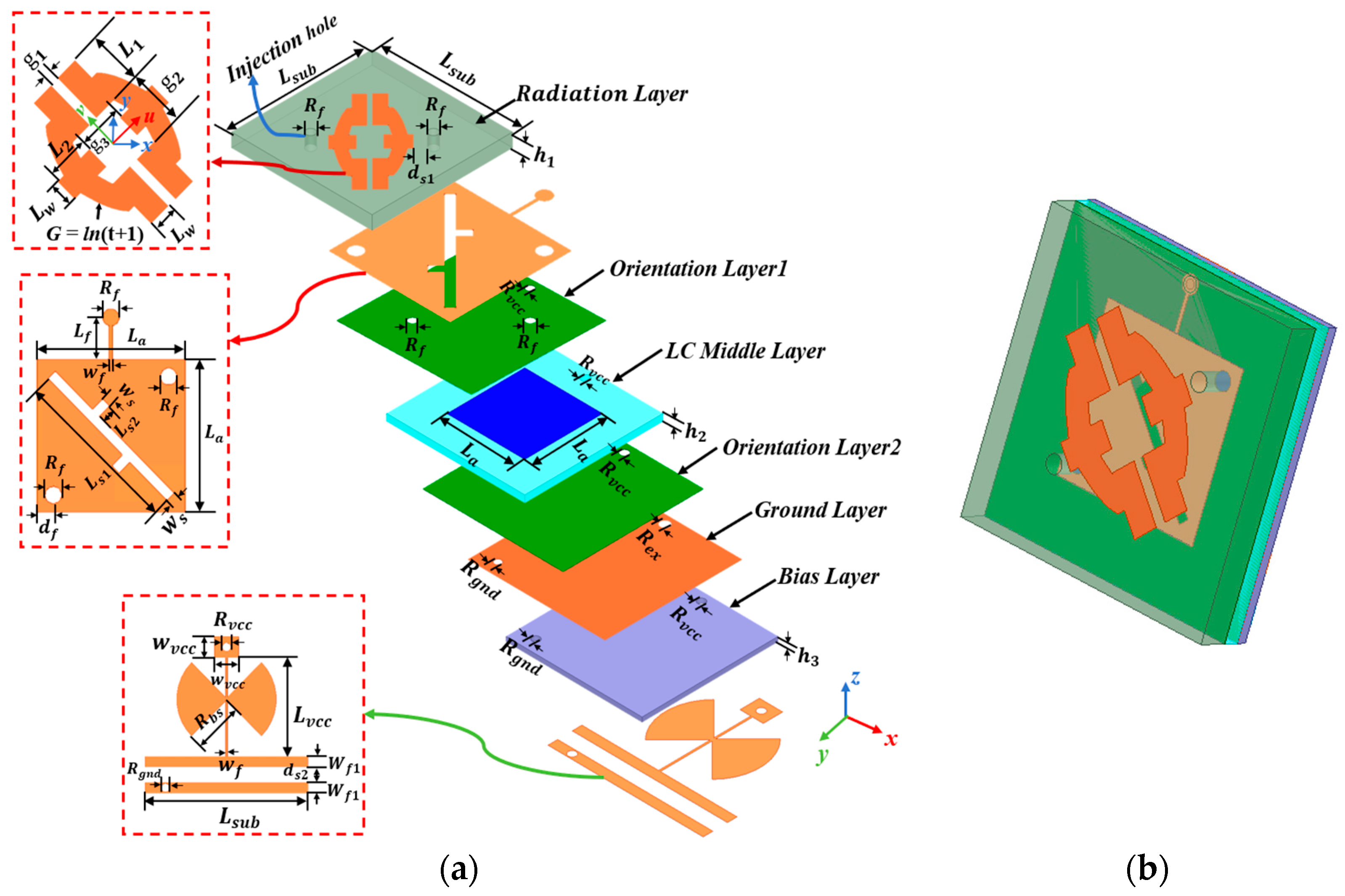
2.1. Unit Cell Structure Design

Figure 1 illustrates the geometry and corresponding dimensional parameters of the optimized polarization-converting RMS unit cell. The unit cell has dimensions of 16 × 16 × 2.794 mm3 and consists of a 6-layer stacked structure, as shown in Figure 1a,b, from top to bottom, the polarization conversion radiation layer, orientation layer 1, LC middle layer, orientation layer 2, ground layer, and bias layer. The dielectric substrates of both the polarization conversion radiation layer and the LC middle layer are made of Rogers RT5880 material, which has a relative dielectric constant of 2.2 and a loss angle tangent of 0.0009. The polarization conversion radiation layer contains two drill holes: one for exhaust and the other for LC injection. The outer surface of the top layer is designed based on the logarithmic function expression G = ln(t + 1), where t ranges from 0 to 3.7 mm. The inner surface is slotted with a cross-like slit structure to facilitate caliber coupling feed, and the patch serves as the positive electrode for the biased DC power supply. Both patches are symmetric with respect to the u- and v-axes, where the u-axis is oriented at +45° relative to the x-axis, and the v-axis is oriented at +45° relative to the y-axis. The LC middle layer contains skeletonized grooves for LC filling. The second and fourth layers are orientation layers, which are made by spin-coating a polyimide solution, high-temperature curing, and friction processing. They have a relative dielectric permittivity of 4.3 and a loss angle tangent of 0.004, and they are primarily used to pre-orient the LC molecules. The ground and other metal radiation patches are made of copper, with a conductivity σ = 5.8 × 10⁷ S/m and a thickness of 35 um. The grounded metal patch acts as the negative electrode for the DC power supply. The sixth layer is the DC bias layer, and Rogers 4350B is used as the dielectric substrate with a relative permittivity of 3.66 and a loss angle tangent of 0.0037. The DC bias circuit features a fan-shaped branch structure. Table 1 demonstrates the specific values of the optimized MS parameters.

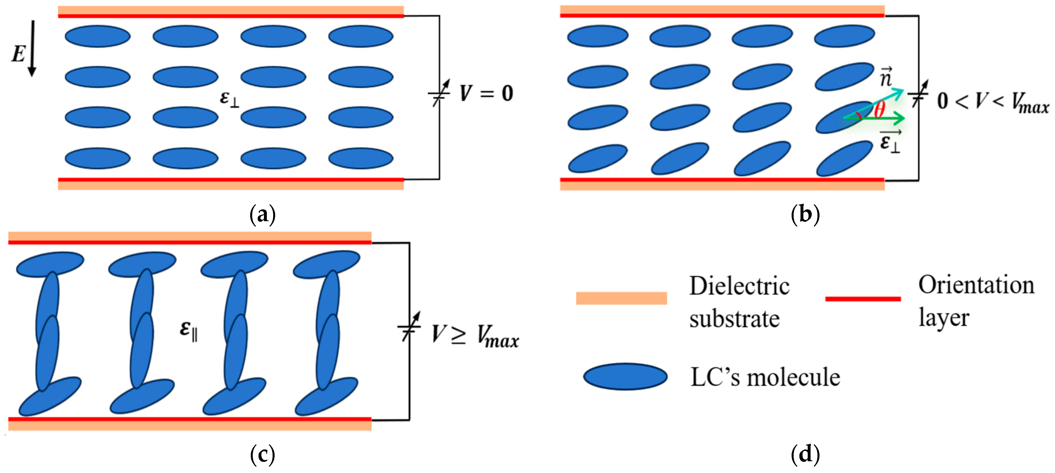
2.2. Electromagnetic Properties of LC Materials

LC materials are primarily classified into thermotropic LCs, solvatropic LCs, and polymeric LCs. LCs are a unique class of polymer compound materials between liquids and solids, combining the fluidity of liquids and the anisotropy of crystals [29]. In this study, thermotropic nematic-phase LCs with dielectric anisotropies are selected as tunable materials for RMS. Nematic phase LCs are composed of uniaxial rod-shaped molecules, which can move between molecular layers, have superior mobility, simple orientation control, and low threshold voltage, which makes them widely used in the field of microwave device tuning. When different bias voltages are applied, the orientation of the nematic LC molecules determines the dielectric constant tensor in various deflection states [30].
Figure 2 demonstrates the deflection characteristics of nematic phase LC molecules under different applied bias voltages [29]. Different cases of LC molecules and dielectric constant variation with applied bias voltage are shown in Figure 2a, b, and c, respectively, where V m a x denotes the critical maximum voltage, and ε e f f is the effective dielectric constant of the LC. E is the electric field direction of the applied bias voltage. When the applied voltage is below the threshold voltage ( V t h ), which is insufficient to deflect the LC molecules, the LC molecules align perpendicular to the electric field, with a dielectric constant of ε and a corresponding tangent loss of tan δ . As the voltage reaches V m a x , the LC molecules will be parallel to the electric field, with a dielectric constant of ε and a corresponding tangent loss of tan δ . The dielectric anisotropy of LC is expressed as ε r = ε r , ε r , (where ε r , ε and ε r ,   ε ). The varying rotational angles of the LC molecules under externally applied bias voltages correspond to different dielectric constants of the LCs. The pointing vectors, n , of these molecules determine the dielectric constant tensor in different deflected states, with θ representing the angle of molecular deflection.
When n = ( cos θ , 0 , sin θ ) , its relative dielectric constant can be expressed as [29]:
ε r = ε + ε r cos 2 θ 0 ε r sin θ cos θ 0 ε 0 ε r sin θ cos θ 0 ε + ε r sin 2 θ
When no bias voltage is loaded, n is perpendicular to the direction of the electric field, the LC molecules are not deflected, θ is approximated to be 0°, and the LC relative dielectric tensor matrix is:
ε r = ε 0 0 0 ε 0 0 0 ε
When the loaded bias voltage is greater than V m a x , n is parallel to the direction of the electric field, and θ is approximated to be 90°, the relative dielectric tensor matrix of the LC is:
ε r = ε 0 0 0 ε 0 0 0 ε
The relative electrical tunability of the nematic phase LC material is:
τ =   ε r ε r , = ε r , ε r , ε r ,
As the arrangement of LC molecules becomes more disordered at high temperatures, the intermolecular interactions are modified, leading to a decrease in the dielectric constant and an increase in the loss factor at elevated temperatures, while the opposite trends occur at low temperatures. Therefore, this study employs the LC-BYIPS-P02 model of positively orientated column phase LCs provided by Shanghai Hengshang Precision Instrument Co., Ltd., Shanghai, China, which exhibits lower sensitivity to temperature fluctuations and has more stable dielectric properties. The characteristics of this LC material at room temperature are as follows: ε = 2.6 , ε = 5.2 , its loss tangent tan δ = 0.0153, and tan δ = 0.0376.

3. Simulation Results of Unit Cell and Theory Analysis of LCPC

To achieve the proposed MS with dual polarization conversion properties, the unit cell needs to be capable of controlling both the amplitude and phase of EM waves. When an x- or y-polarization plane wave is incident on the top surface of the RMS unit cell, the incident electric field can be represented as:
E i x y =   E i x y e x p ( j φ i x y ) e i x y
where e i x y denotes the unit vector of the incident wave.
Due to the anisotropy of the structure, the polarization direction of the EM wave is altered, and the reflected wave can be decomposed into two orthogonal field components. Consequently, the reflected electric field can be expressed as:
E r =   E r x e x p ( j φ r x ) e r x +   E r y e x p ( j φ r y ) e r y
where E r x and E r y are the amplitudes of the reflected wave in the x- and y-direction electric field components, respectively.   φ r x and φ r y are the corresponding phases of the reflected wave in the x- and y-direction electric field components. Additionally, e r x and e r y are the unit vectors of the reflected wave in the x- and y-directions, respectively. Similarly, as shown in [31], the reflected electric field, E r , can also be expressed as:
E r = E x r E y r = R · E i = r x x r x y r y x r y y E x i E y i
where r x x and r y y represent the co-polarized reflection coefficient amplitude components for vertical polarization (VP) and horizontal polarization (HP) waves, respectively. Meanwhile, r x y and r y x denote the cross-polarized reflection coefficient amplitude components for both. For instance, considering x-polarization (i.e., horizontal polarization), where r x x =   E x r / E x i , r y x =   E y r / E x i . When r x x =   r y x and the phase difference φ y x =   φ x x φ y x =   2 k 0 π   ±   π / 2 ( k 0 takes an integer), LCPC is achieved.
If the AR of the reflected EM wave is less than 3 dB, the reflected wave can be considered as a CP wave, and the formula for calculating the AR is as follows [23,32]:
A R =   R + , + 2 + R , + 2 + a R + , + 2 + R , + 2 a 1 / 2
where a = R + , + 4 + R , + 4 +2 R + , + 2   R , + 2 cos( 2 φ , + ), + and − refer to the polarization signs of the incident and reflected waves, respectively. Additionally, φ , + = φ + + φ + . To specifically probe the LCPC, some parameters are introduced, where the incident EM wave is either x or y-polarized. The reflection coefficients for the LCPC are LHCP and RHCP, and the right-handed circular polarization conversion rate ( P C R R H C P y ) for a y-polarized incident wave can be expressed as follows:
r R H C P x = 2 2 ( R x x + i R y x ) r L H C P x = 2 2 ( R x x i R y y ) r R H C P y = 2 2 ( R x y + i R y y ) r L H C P y = 2 2 ( R x y i R y x )
P C R R H C P y = r R H C P y 2 r R H C P y 2 + r L H C P y 2
The simulation results of the MS unit cell under an incident y-polarized EM wave are shown in Figure 3. Figure 3a shows the co- and cross-polarized ( r y y and r x y ) amplitude components for different LC dielectric constants. Figure 3b displays the phase difference φ x y between the co- and cross-polarized components for different LC dielectric constants. By combining Figure 3a,b, it can be observed that the LCPC conditions are met as follows: for ε r = 2.8 , frequency intervals within 8.14–8.48 GHz and 9.84–12.52 GHz, r y y r x y , φ x y are −90° and 90°, respectively. For ε r = 3.9 , frequency intervals within 8.32–8.43 GHz, 9–9.11 GHz, and 9.86–11.83 GHz, and r y y r x y , φ x y are 90°, −90°, and 90°, respectively. ε r = 4.6 , and r y y r x y for frequency intervals within 8.96–9.11 GHz and 9.95–11.51 GHz, with phase differences of −90° and 90°, respectively. The results calculated for the incidence of x- or y-polarized EM waves are shown in Figure 4. Figure 4a,b show the magnitude components of the reflection coefficients of the reflection coefficients for the two CP reflections, calculated under the incidence of x- and y-polarized EM waves, respectively. It is evident that the reflected CP waves, obtained for an incident x- or y-polarized EM wave, propagate in opposite directions at the same frequency. This behavior results from the orthogonal symmetry of the unit cell, which has a diagonal 45° structure. The system is reciprocal, meaning that the unit cell exhibits symmetric behavior in the direction of signal transmission. For an incident x-polarized EM wave, with ε r = 2.8 , the reflected EM waves are primarily composed of LHCP and RHCP, with amplitudes exceeding 0.98 in the frequency ranges 8.15–8.46 GHz and 9.84–12.52 GHz, respectively. When ε r = 3.9 , the reflected EM waves are dominated by LHCP with amplitudes above 0.96 in the frequency range 9–9.11 GHz. In the frequency interval of 9.86–11.81 GHz, the reflected EM waves are dominated by RHCP with amplitudes above 0.98. For ε r = 4.6 , the reflected EM waves are dominated by LHCP and RHCP with amplitudes greater than 0.96 in the frequency ranges 8.96–9.11 GHz and 9.95–11.51 GHz, respectively.
Figure 5 shows the computationally obtained results after simulating the MS unit cell at the incidence of a y-polarized EM wave. In Figure 5a, as the dielectric constant of the LC decreases, the ARBW gradually increases, which also corresponds to different frequency ranges in the x-band, making it suitable for flexible scheduling of the resulting circularly polarized waves. For ε r = 2.8 , AR < 3 dB in the frequency intervals 8.14–8.48 GHz and 9.84–12.52 GHz, with fractional bandwidths (FBWs) of 4.09% and 23.97%, respectively. And AR < 1 dB in the frequency ranges of 8.28–8.36 GHz and 10.18–12.06 GHz, with FBWs of 0.96% and 16.91%. For ε r = 3.9 , the frequency intervals within 8.37–8.43 GHz, 9.01–9.11 GHz, and 9.86–11.83 GHz, AR < 3 dB, and FBWs are 0.71%, 1.1% and 18.17%, respectively. In the frequency range of 10.17–11.45 GHz, AR < 1 dB, and FBW is 11.84%. For ε r = 4.6 , AR < 3 dB, and 1.66% and 14.54% for FBWs within the frequency intervals 8.96–9.11 GHz and 9.95–11.51 GHz, respectively, and 7.66% for FBW, AR < 1 dB within the frequency intervals 10.3–11.12 GHz, respectively. In Figure 5b, the polarization conversion ratios (PCRs) exceed 0.98 (greater than 98%) in the following frequency ranges: 8.17–8.45 GHz and 9.9–12.43 GHz for ε r = 2.8 , 9.92–11.75 GHz for ε r = 3.9 , and 8.98–9.1 GHz and 10.01–11.44 GHz for ε r = 4.6 .
The surface current distribution of the unitary radiating patch at ε r = 2.8 is investigated under vertical positive feed incidence of y-polarized wave (φ = 90°, θ = 0°) at operating frequencies of 8.24 GHz and 11 GHz, respectively. This analysis reveals the mechanism behind the transition between linear and circular polarization. At a frequency of 8.24 GHz in Figure 6a, the surface current vectors of the primary radiating patch rotate counterclockwise as the resonance phase increases from 0° to 270°, indicating the achievement of RHCP. Conversely, Figure 6b demonstrates that at a frequency of 11 GHz, the surface current vector shows clockwise rotation, indicating that the conversion of LHCP is achieved.
Typically, for an LP wave, the EM wave can be decomposed into two components along orthogonal directions, denoted as u and v, as illustrated in Figure 1. These components are symmetric about the y-axis, with angles of −45° and 45° relative to the y-axis, respectively. Due to the anisotropic nature of the subsurface, the co-polarized reflection coefficients ( r u u , r v v ) are independent, yet their magnitudes are nearly equal to 1.0, owing to the low dielectric loss. Therefore, neglecting the minimum dielectric loss, the following equation can be derived: r v v = r u u e j φ u v , and the electric field unit vectors for the x- and y-polarized waves can be expressed using the u and v-axis as follows: e x = 2 2 ( e u e v ) and e y =   2 2 ( e u + e v ) [33], where e u and e v are the unit vectors along the u and v axes, respectively, and the phase difference, φ u v = φ u u φ v v . Assuming a vertically incident y-polarized wave as an input ( E i = E 0 e y =   2 2 ( e u + e v ) ), and using Equations (6) and (7), the reflected EM waves are characterized as follows: E r = E u r e u + E v r e v , which can be simplified as follows:
E r = E 0 2 [ ( r u u + r v v ) e y + ( r u u r v v ) e x ]
where r y y and r x y can be summarized as follows: r y y = 1 2 r u u + r v v = 1 2 r u u ( 1 + e j φ u v ) and r x y = 1 2 r u u r v v = 1 2 r u u ( 1 e j φ u v ) . Then, the reflection coefficient matrix ( R l i n ) can be converted into:
R l i n = r x x r x y r y x r y y = 1 2 r u u 1 + e j φ u v 1 e j φ u v 1 e j φ u v 1 + e j φ u v
Therefore, based on Equation (12), the following equation can be demonstrated [31]:
r x x r y x = r y y r x y = 1 + e j φ u v 1 e j φ u v = 1 + cos φ u v j sin φ u v 1 cos φ u v + j sin φ u v = j sin φ u v 1 cos φ u v
Equation (13) depicts that the ratio between the co- and cross-polarized reflection coefficients is a purely imaginary number for both x- and y-polarized incidences. This implies that the absolute value of the phase difference between them will always be equal to 90°, which helps explain why the absolute value of the phase difference φ x y , as shown in Figure 3b, the absolute value remains approximately 90° within certain frequency bands of the spectrum. The proposed unit cell was simulated under illumination by a 45° linearly polarized (LP) wave, as illustrated in Figure 7a,b. For ε r = 2.8 , the reflection coefficients r u u and r v v exhibit near-equality (   r u u r v v ) within two frequency bands: 8.15–8.5 GHz and 9.84–12.54 GHz, with magnitudes exceeding 0.96.Additionally, the phase difference φ u v =   ± 90 ° with a deviation of ± 10 ° . This provides additional evidence supporting the mechanism of LCPC.

4. Discussion

Except for Figure 6, which was simulated using CST 2016 Microwave Studio, other simulation data were obtained using the ANSYS HFSS 2014 EM simulation software. To validate the proposed design, an MS consisting of 6 × 6 cells is fabricated. Full-wave simulations were performed on this MS prototype. Its radiation performance was tested using Ceyear-3671D vector network analyzer (VNA), Midrand, South Africa and Xiang tong OTA microwave anechoic chamber, Guangzhou, China.

4.1. Actual Test Environment Setup

The physical structure of the layers of a machined 6 × 6 unit cell prototype is shown in Figure 8a, with an overall size of 128 × 128 × 2.794 mm3. The DC power supply and the MS feed setup are illustrated in Figure 8b. Two standard feed horns were used as transmitter and receiver antennas, respectively. The transmitter horn was used to feed the vertical LP wave to the MS under test (MUT), while the receiver horn collected the reflected EM wave signals. It is important to note that during the actual testing, after adjusting the DC voltage, a waiting period was required before the testing could commence. This delay is due to the hysteresis effect in the electro-optical response of the liquid crystals (LCs), meaning the electric field generated by the new voltage cannot be uniformly distributed immediately, which may lead to an inconsistent arrangement of the LC molecules, resulting in an unstable tuning mechanism. Furthermore, to prevent leakage of the LCs, UV-curable adhesive was used for interlayer bonding, and the injection holes were sealed after the LC injection. The test environment was maintained at a temperature of approximately 20 °C. Figure 8c depicts the actual test setup in the OTA microwave anechoic chamber. The MS to be tested and the transmitting horn were fixed on a wooden frame to minimize errors.

4.2. Comparison and Analysis of Measurement and Simulation Results

Figure 9 depicts the values of AR of the MS at different frequencies for two kinds of LP waves in x and y directions with the addition of 8.6 v and 19.8 v DC voltage, corresponding to dielectric constants of ε r = 2.8 and ε r = 4.6 , respectively. In Figure 9a, for ε r = 2.8 , the AR< 3 dB within the frequency ranges of 8.16–8.46 GHz and 9.86–12.48 GHz, with FBWs of 3.61% and 23.46%, respectively. In Figure 9b, for ε r = 4.6 , the AR< 3 dB for the frequency intervals within 9.78–11.34 GHz, with FBW of 14.77%. Figure 10 presents a comparison of the directivity coefficients of the MS for incident x- and y-direction polarization waves, with dielectric constants of ε r = 2.8 and ε r = 4.6 . From Figure 10a, it can be seen that the x-polarized wave is converted to LHCP and RHCP, i.e., DirTotal ≈ DirLHCP, and DirTotal ≈ DirRHCP, respectively, for ε r = 2.8 and the frequency intervals within 8.12–8.52 GHz and 9.76–12.78 GHz, respectively. Figure 10b illustrates the conversion of the x-polarized wave to RHCP, i.e., DirTotal ≈ DirRHCP, for ε r = 4.6 , within the frequency range of 9.8–11.78 GHz. Comparing Figure 10a,c, it can be seen that changing the x- to a y-polarized wave alters the direction of the reflected CP wave within the same frequency band and will not have an effect on the frequency band of the LCPC. In Figure 10c, for ε r = 2.8 , the y-polarized wave is converted to RHCP and LHCP for the frequency intervals within 8.12–8.52 GHz and 9.76–12.78 GHz, respectively. In Figure 10d, for ε r = 4.6 , the y-polarized wave is converted to LHCP within the frequency range of 9.8–11.78 GHz. The comparison between the simulation and measured results in Figure 9 and Figure 10 shows good agreement, verifying the validity of the design. However, some deviation remains between the two datasets. This deviation could be attributed to the limitations in the fabrication process of the MS. Specifically, the high temperature used to produce the polyimide during the fabrication of the orientation layer may cause some damage to the layer. Additionally, the distribution of LC molecules during the encapsulation process might be inhomogeneous. Air residues between the layers in the stacked MS structure could also reduce the dielectric constant of the dielectric layer, among other factors, contributing to the observed deviation. Table 2 lists the properties of the proposed MS and compares them with other related works published in the literature.

5. Conclusions

In this paper, a novel design of polarization-converted RMS is proposed, which utilizes an applied DC bias voltage to regulate the relative permittivity of LCs, thereby modulating the MS properties. The design enables the realization of a dual-LCPC function across multiple frequency bands, where the reflected EM wave can be either LHCP or RHCP, and the incident EM wave can be either x- or y-polarized. This approach enhances the potential for x-band applications to a certain extent. The proposed MS not only overcomes the limitation of conventional designs, which typically operate in a single frequency band or a single LP wave, but also adapts to the diverse communication requirements across different regions and standards. Consequently, it allows the communication system to support more simultaneous user access, significantly improving both the stability and flexibility of its performance. The proposed MS expands the wide range of application prospects in wireless communication, radar, remote sensing, and other fields.

Author Contributions

Conception, design, data collection, analysis, simulation, and measurement were initially carried out by P.C. and X.W.; L.L., L.T., Y.Y., and H.Z. contributed to completing the writing and presentation of the whole manuscript. All authors have read and agreed to the published version of the manuscript.

Funding

This work was supported by Fujian Provincial Science and Technology Department’s Industrial Guidance Projects (2024H0018) and the Xiamen Industry–University–Research Subsidy Project (2023CXY0303, 2024CXY0311).

Institutional Review Board Statement

Not applicable.

Informed Consent Statement

Not applicable.

Data Availability Statement

The original contributions presented in this study are included in the article. Further inquiries can be directed to the corresponding author.

Conflicts of Interest

The authors declare no conflicts of interest.

References

  1. Ullah, U.; Mabrouk, I.B.; Koziel, S. A Compact Circularly Polarized Antenna with Directional Pattern for Wearable Off-Body Communications. IEEE Antennas Wirel. Propag. Lett. 2019, 18, 2523–2527. [Google Scholar] [CrossRef]
  2. Ullah, U.; Koziel, S.; Mabrouk, I.B. Rapid Redesign and Bandwidth/Size Tradeoffs for Compact Wideband Circular Polarization Antennas Using Inverse Surrogates and Fast EM-Based Parameter Tuning. IEEE Trans. Antennas Propag. 2020, 68, 81–89. [Google Scholar] [CrossRef]
  3. Ullah, U.; Al-Hasan, M.; Koziel, S.; Mabrouk, I.B. Circular Polarization Diversity Implementation for Correlation Reduction in Wideband Low-Cost Multiple-Input-Multiple-Output Antenna. IEEE Access 2020, 8, 95585–95593. [Google Scholar] [CrossRef]
  4. Deng, G.; Zhu, Y.; Zhang, Q.; Zhang, G.; Yin, Z.; Yang, J.; Li, Y. Reconfigurable Linear-to-Circular Polarization Conversion Using Liquid Crystal-Based Reflective Metasurface. IEEE Antennas Wirel. Propag. Lett. 2024, 23, 2249–2253. [Google Scholar] [CrossRef]
  5. Li, A.; Singh, S.; Sievenpiper, D. Metasurfaces and Their Applications. Nanophotonics 2018, 7, 989–1011. [Google Scholar] [CrossRef]
  6. Hu, J.; Bandyopadhyay, S.; Liu, Y.-h.; Shao, L.-Y. A Review on Metasurface: From Principle to Smart Metadevices. Front. Phys. 2021, 8, 586087. [Google Scholar] [CrossRef]
  7. Qian, Y.-J.; Wang, Y.-B.; Yang, X.-D.; Wang, J.; Yan, Y.-Z. Manipulation of circular polarization and mechanical waves in gyroscopic metamaterials. Phys. Rev. Appl. 2024, 22, 054016. [Google Scholar] [CrossRef]
  8. Lin, X.; Shen, Z.; Huang, D. Broadband circular polarization selector and converter based on multilayer metamaterials with stacked split-rings. Phys. Rev. Mater. 2024, 8, 015203. [Google Scholar] [CrossRef]
  9. Dutta, R.; Ghosh, J.; Yang, Z.; Zhang, X. Multi-Band Multi-Functional Metasurface-Based Reflective Polarization Converter for Linear and Circular Polarizations. IEEE Access 2021, 9, 152738–152748. [Google Scholar] [CrossRef]
  10. Li, J.; Yuan, Y.; Wu, Q.; Zhang, K. Bi-Isotropic Huygens’ Metasurface for Polarization-Insensitive Cross-Polarization Conversion and Wavefront Manipulation. IEEE Trans. Antennas Propag. 2024, 72, 2445–2454. [Google Scholar] [CrossRef]
  11. Khan, M.; Hu, B.; Chen, Y.; Ullah, N.; Khan, M.J.I.; Khalid, A.U.R. Multiband Efficient Asymmetric Transmission with Polarization Conversion Using Chiral Metasurface. IEEE Antennas Wirel. Propag. Lett. 2020, 19, 1137–1141. [Google Scholar] [CrossRef]
  12. Kang, W.; Chen, S.; Li, Y.; Sima, B.; Wu, W. Simultaneous Polarization Conversion and Retro-reflection Based on Surface-Circuit Metasurfaces. IEEE Antennas Wirel. Propag. Lett. 2023, 22, 2002–2006. [Google Scholar] [CrossRef]
  13. Zheng, Q.; Guo, C.; Ding, J. Wideband Metasurface-Based Reflective Polarization Converter for Linear-to-Linear and Linear-to-Circular Polarization Conversion. IEEE Antennas Wirel. Propag. Lett. 2018, 17, 1459–1463. [Google Scholar] [CrossRef]
  14. Zhao, X.-B.; Wei, F.; Shi, X.W.; Zeng, C. Broadband Folded Reflectarray Antenna Using Single-Layer Cross-Polarization Conversion Subwavelength Elements. IEEE Antennas Wirel. Propag. Lett. 2021, 20, 612–616. [Google Scholar] [CrossRef]
  15. Zhang, P.-P.; Zhu, X.-C.; Hu, Y.; Hao, Z.-C.; Luo, G.-Q. A Wideband Circularly Polarized Folded Reflectarray Antenna with Linearly Polarized Feed. IEEE Antennas Wirel. Propag. Lett. 2022, 21, 913–917. [Google Scholar] [CrossRef]
  16. Yang, Y.-H.; Sun, B.-H.; Guo, J.-L. A Single-Layer Wideband Circularly Polarized Antenna for Millimeter-Wave Applications. IEEE Trans. Antennas Propag. 2020, 68, 4925–4929. [Google Scholar] [CrossRef]
  17. Yang, X.; Wen, E.; Bharadia, D.; Sievenpiper, D.F. Multifunctional Metasurface: Simultaneous Beam Steering, Polarization Conversion, and Phase Offset. IEEE Trans. Antennas Propag. 2024, 72, 4589–4593. [Google Scholar] [CrossRef]
  18. Gao, X.; Qi, J.C.; Lan, F.; Wang, G.F.; Xie, X.M.; Li, H.Y. 1-Bit Metasurface-Based Beam-Scanning Circularly Polarized Folded Reflector Antenna. IEEE Antennas Wirel. Propag. Lett. 2024, 23, 638–642. [Google Scholar] [CrossRef]
  19. Bhattacharjee, A.; Dwari, S.; Mandal, M.K. Polarization-Reconfigurable Compact Monopole Antenna with Wide Effective Bandwidth. IEEE Antennas Wirel. Propag. Lett. 2019, 18, 1041–1045. [Google Scholar] [CrossRef]
  20. Cui, Y.; Qi, C.; Li, R. A Low-Profile Broadband Quad-Polarization Reconfigurable Omnidirectional Antenna. IEEE Trans. Antennas Propag. 2019, 67, 4178–4183. [Google Scholar] [CrossRef]
  21. Yu, H.; Zhang, Z.; Su, J.; Qu, M.; Li, Z.; Xu, S.; Yang, F. Quad-Polarization Reconfigurable Reflectarray with Independent Beam-Scanning and Polarization Switching Capabilities. IEEE Trans. Antennas Propag. 2023, 71, 7285–7298. [Google Scholar] [CrossRef]
  22. Yan, X.; Li, L.; Zhang, H.; Han, J. Broadband Polarization-Reconfigurable Liquid Dielectric Resonator Antenna Controlled by Gravity. IEEE Antennas Wirel. Propag. Lett. 2022, 21, 2105–2109. [Google Scholar] [CrossRef]
  23. Majeed, A.; Zhang, J.; Awan, Z.A.; Memon, S.; Ishfaq, M.; Wang, C. A High-Efficiency Dual-Band Linear-to-Circular Polarization Converter Based on Rectangular-Slot Reflective Metasurface. Appl. Sci. 2022, 12, 9172. [Google Scholar] [CrossRef]
  24. Park, J.; Yoo, Y.; Lee, C.; Yoon, D.K.; Park, S.-O. Liquid-Crystal-Based Beam-Steering Guided-Wave Metasurface Antenna at Millimeter-Wave Band. IEEE Antennas Wirel. Propag. Lett. 2024, 23, 4208–4212. [Google Scholar] [CrossRef]
  25. Yin, S.; Xiao, D.; Liu, J.; Li, K.; He, H.; Jiang, S.; Luo, D.; Sun, X.W.; Ji, W.; Liu, Y.J. Reconfigurable Chiral Metasurface Absorbers Based on Liquid Crystals. IEEE Photonics J. 2018, 10, 1–9. [Google Scholar] [CrossRef]
  26. Chen, Q.; Zhang, H. Dual-Patch Polarization Conversion Metasurface-Based Wideband Circular Polarization Slot Antenna. IEEE Access 2018, 6, 74772–74777. [Google Scholar] [CrossRef]
  27. Wang, Y.; Zhang, A. Dual Circularly Polarized Fabry–Perot Resonator Antenna Employing a Polarization Conversion Metasurface. IEEE Access 2021, 9, 44881–44887. [Google Scholar] [CrossRef]
  28. Li, E.; Li, X.J.; Seet, B.-C.; Ghaffar, A.; Aneja, A. A Metasurface-Based LTC Polarization Converter with S-Shaped Split Ring Resonator Structure for Flexible Applications. Sensors 2023, 23, 6268. [Google Scholar] [CrossRef]
  29. Chen, P.; Wang, D.; Wang, L.; Liu, L.; Gan, Z. Liquid Crystal-Based Reconfigurable Antenna for 5G Millimeter-Wave. Sci. Rep. 2024, 14, 2045–2322. [Google Scholar] [CrossRef]
  30. Zhang, W.; Li, Y.; Zhang, Z. A Reconfigurable Reflectarray Antenna with an 8 μm-Thick Layer of Liquid Crystal. IEEE Trans. Antennas Propag. 2022, 70, 2770–2778. [Google Scholar] [CrossRef]
  31. Fei, P.; Guo, W.; Hu, W.; Zheng, Q.; Wen, X.; Chen, X.; Vandenbosch, G.A.E. A Transmissive Frequency-Reconfigurable Cross-Polarization Conversion Surface. IEEE Antennas Wirel. Propag. Lett. 2022, 21, 997–1001. [Google Scholar] [CrossRef]
  32. Lin, B.; Lv, L.; Guo, J.; Liu, Z.; Ji, X.; Wu, J. An Ultra-Wideband Reflective Linear-to-Circular Polarization Converter Based on Anisotropic Metasurface. IEEE Access 2020, 8, 82732–82740. [Google Scholar] [CrossRef]
  33. Majeed, A.; Zhang, J.; Ashraf, M.A.; Memon, S.; Mohammadani, K.H.; Ishfaq, M.; Sun, M. An Ultra-Wideband Linear-to-Circular Polarization Converter Based on a Circular, Pie-Shaped Reflective Metasurface. Electronics 2022, 11, 1681. [Google Scholar] [CrossRef]
Figure 1. Structure of the proposed reflective MS unit cell involving LC is listed as: (a) exploded view and dimension parameters, and (b) perspective side view.
Applsci 15 08499 g001
Figure 2. Deflection characteristics of nematic phase LC molecules with applied bias voltage are listed as: (a) without a bias voltage, (b) with a bias voltage ( 0 < V < V m a x ), (c) with a bias voltage (V V m a x ), and (d) elements labeling.
Applsci 15 08499 g002
Figure 3. Simulation results of the MS unit cell under an incident y-polarized EM wave. (a) Co- and cross-polarized ( r y y and r x y ) amplitude components and (b) phase difference ( φ y x ) for different LC dielectric constants.
Applsci 15 08499 g003
Figure 4. Calculated results at the incidence of an x- or y-polarized EM wave. Two CP reflection coefficient magnitude components (LHCP and RHCP) for (a) an incident x-polarized and (b) y-polarized EM waves and different LC dielectric constants.
Applsci 15 08499 g004
Figure 5. Results obtained by calculations at the incidence of a y-polarized EM wave. (a) Axial ratio (dB) and (b) linear-to-circular polarization conversion ratio (PCR).
Applsci 15 08499 g005
Figure 6. ε r = 2.8 , incident wave φ = 90°, θ = 0 ° , (a) surface current distribution in the MS unit cell at 8.24 GHz, and (b) 11 GHz, both with different resonance phases varying from 0° to 270°.
Applsci 15 08499 g006
Figure 7. (a) Magnitude of r u u and r v v and (b) phase difference ( φ u v ) for an incident y-polarized wave, and ε r = 2.8 .
Applsci 15 08499 g007
Figure 8. (a) Physical structure of the layers of the MS prototype and (b) DC feed setup. (c) Microwave anechoic chamber test setup.
Applsci 15 08499 g008
Figure 9. Comparison of the measured and simulated AR results under x- and y-incidence polarized waves is shown as follows: (a) AR (dB) at ε r = 2.8 , 8.6 v x-polarized wave, and (b) ε r = 4.6 , 19.8 v y-polarized wave.
Applsci 15 08499 g009
Figure 10. Comparison of measured and simulated directionality results under x- and y-incidence polarized waves: (a) directionality (dB) at ε r = 2.8 , 8.6 v, x-polarized wave, (b) ε r = 4.6 , 19.8 v, x-polarized wave, (c) directionality (dB) at ε r = 2.8 , 8.6 v, y-polarized wave, and (d) ε r = 4.6 , 19.8 v, y-polarized wave.
Applsci 15 08499 g010
Table 1. Optimized value (in mm) of the proposed RMS unit cell (Para. is parameter).
Para.ValuePara.ValuePara.ValuePara.ValuePara.Value
Lsub16L13.4L22.8g10.6g23.6
g32.7Lw1.5Rf1ds10.3h11.524
La9Lf2.5Ls110.2Ls20.9ws0.6
wf0.4df1Rvcc0.9La9Rex1.4
h20.762h30.508Rgnd0.8Rbs5Lvcc2.5
wvcc2.4wf11ds21.5
Table 2. Comparison of polarization conversion with the previously published works.
Ref.Unit Cell
P (mm)
Substrate
Thickness
h (mm)
No. of Substrate
Layers
3 dB AR
FBW (%)
Polarization Conversion
Mode
LTC PCR (%)No. of Bands
[23]6.01.6135.23 and 26.62y-CP992
[33]6.01.6150.8y-CP981
[26]8.00.5226.2x-CPN.A.1
[27]8.03.235x-CP and
y-CP
N.A.1
[28]13.01.5751N.A.y-CPN.A.single
frequency
(12.4 GHz)
This work16.02.79453.61, 1.1, 18.17, 23.46 and 14.77x-CP and
y-CP
985
N.A. represents not applicable.
Disclaimer/Publisher’s Note: The statements, opinions and data contained in all publications are solely those of the individual author(s) and contributor(s) and not of MDPI and/or the editor(s). MDPI and/or the editor(s) disclaim responsibility for any injury to people or property resulting from any ideas, methods, instructions or products referred to in the content.

