
Hydrogen Storage Vessel for a Proton-Exchange Membrane (PEM) Fuel Cell Auxiliary Power Unit for Commercial Aircraft


Abstract
1. Introduction
2. Methodology
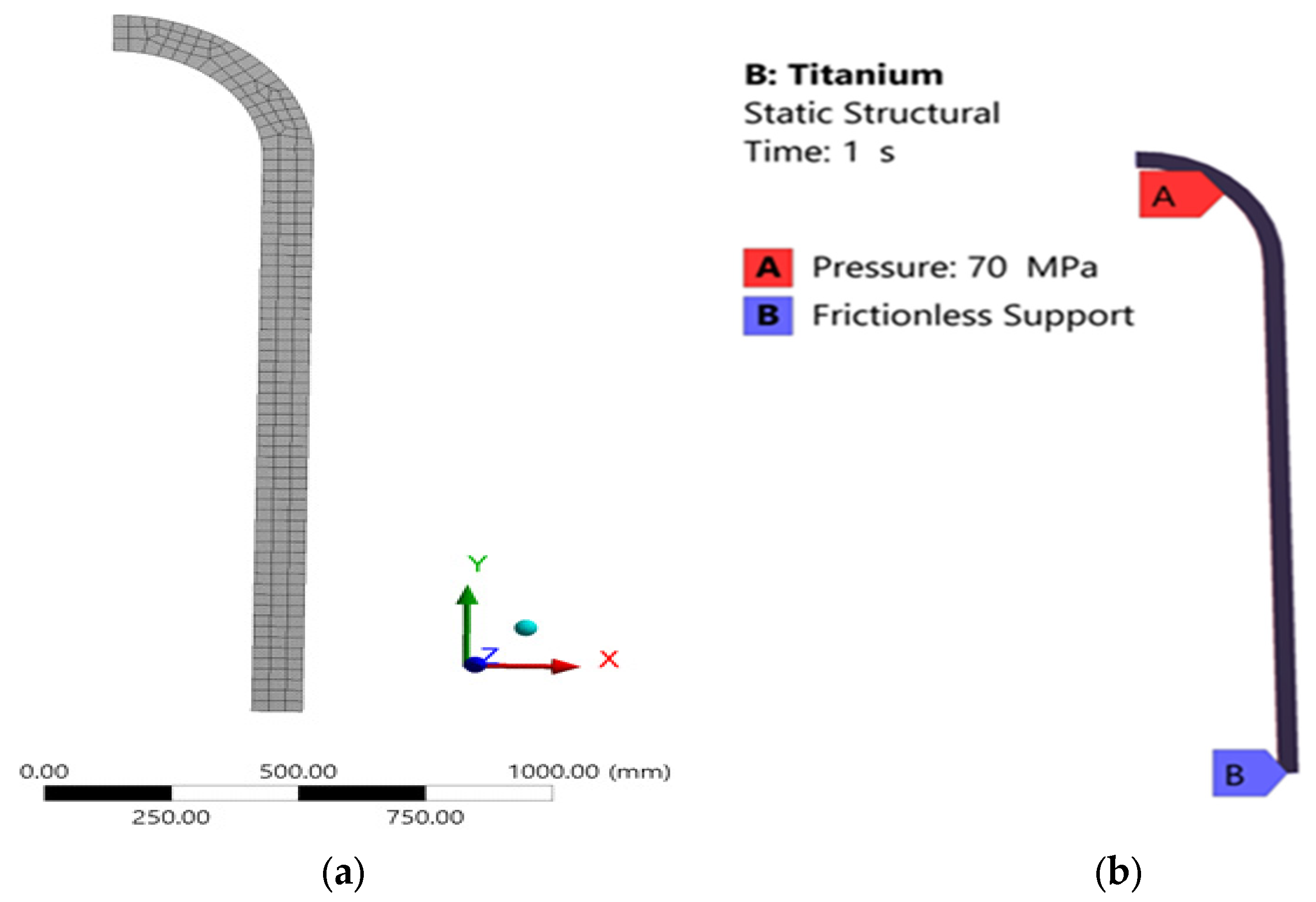
2.1. Hydrogen Vessel Design
2.2. CO2 Emission Calculation
3. Results and Discussion
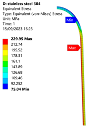
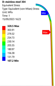
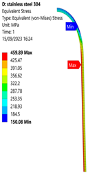
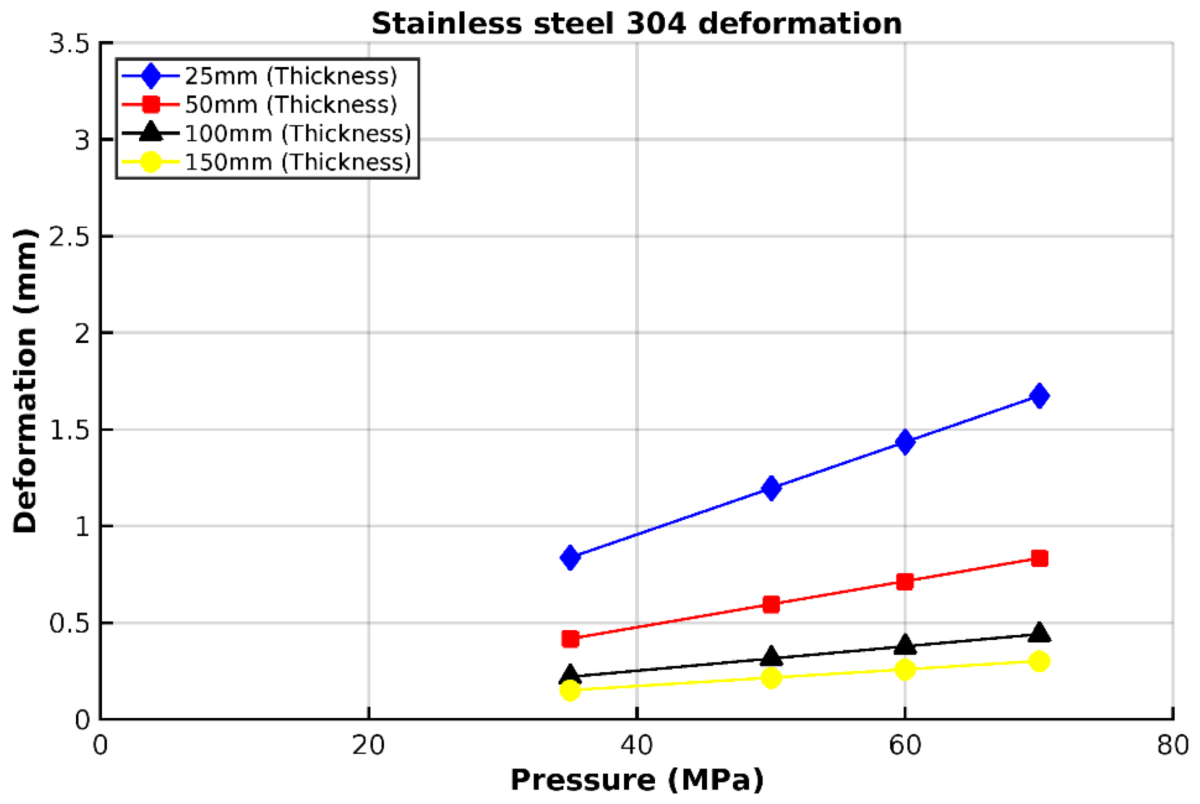
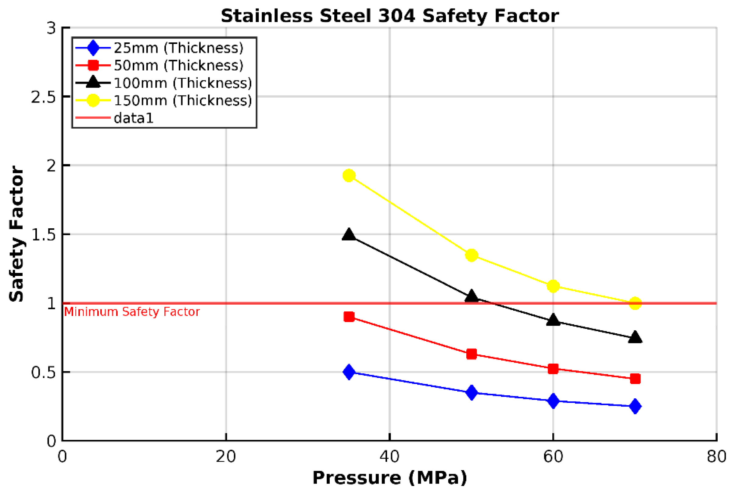
3.1. Analysis of 304 Stainless Steel Vessel
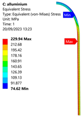
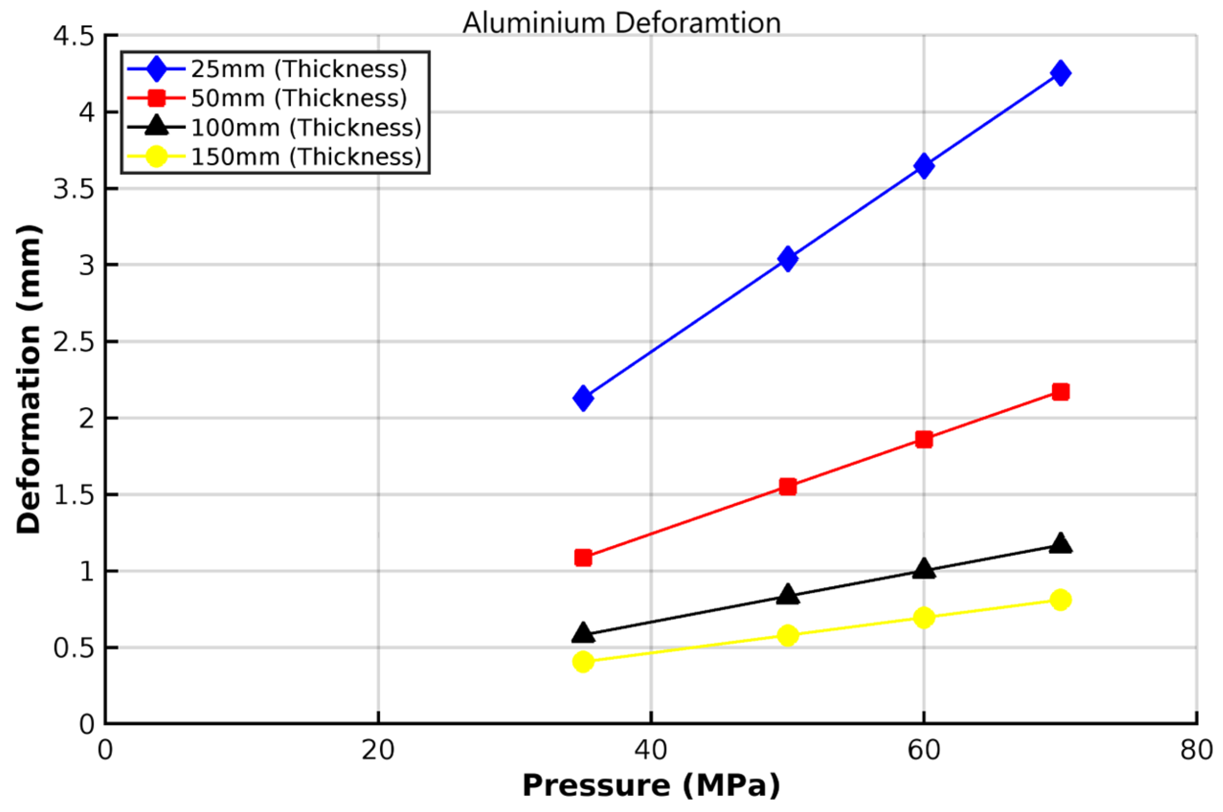
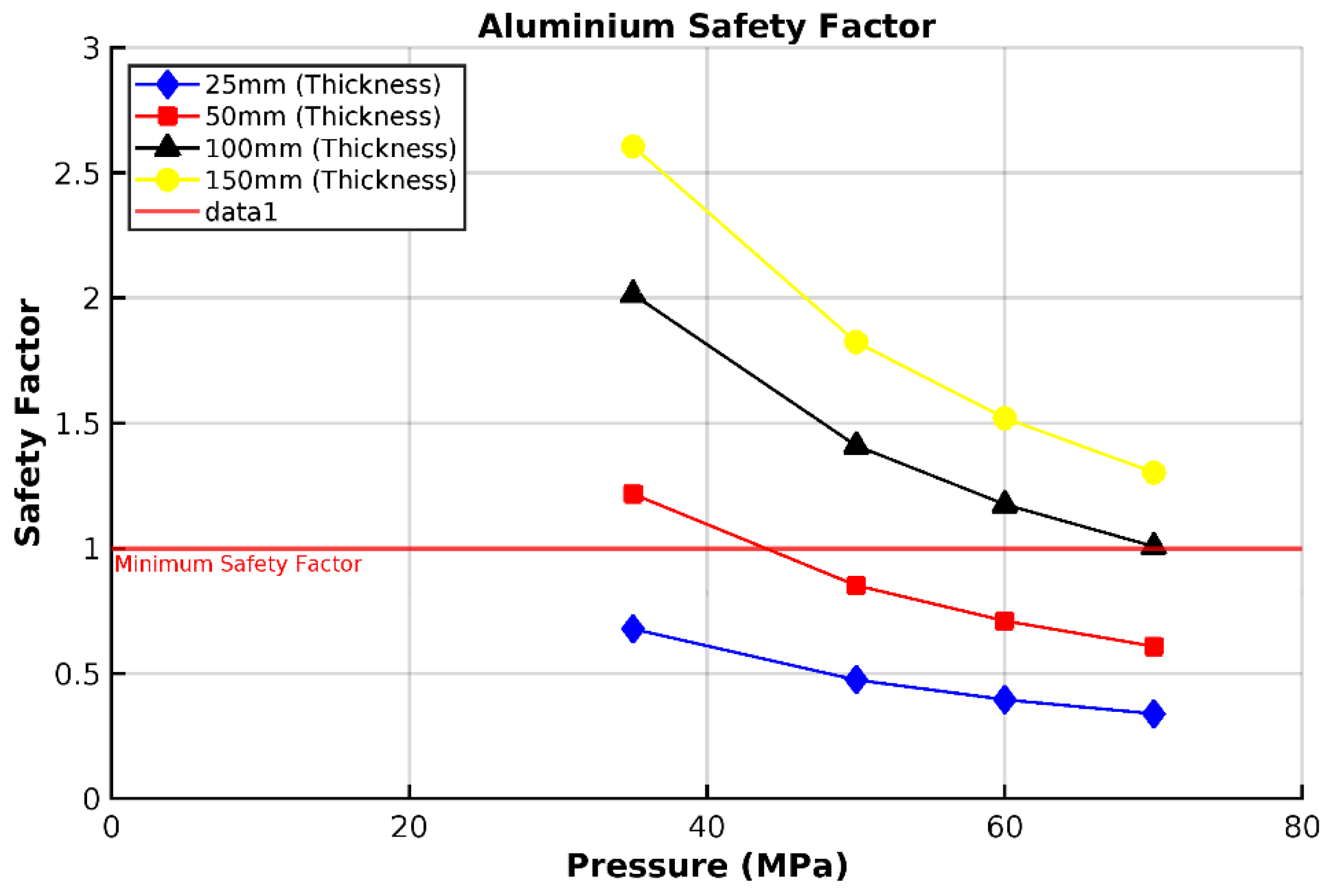
3.2. Analysis of 6061-T6 Aluminium Vessel
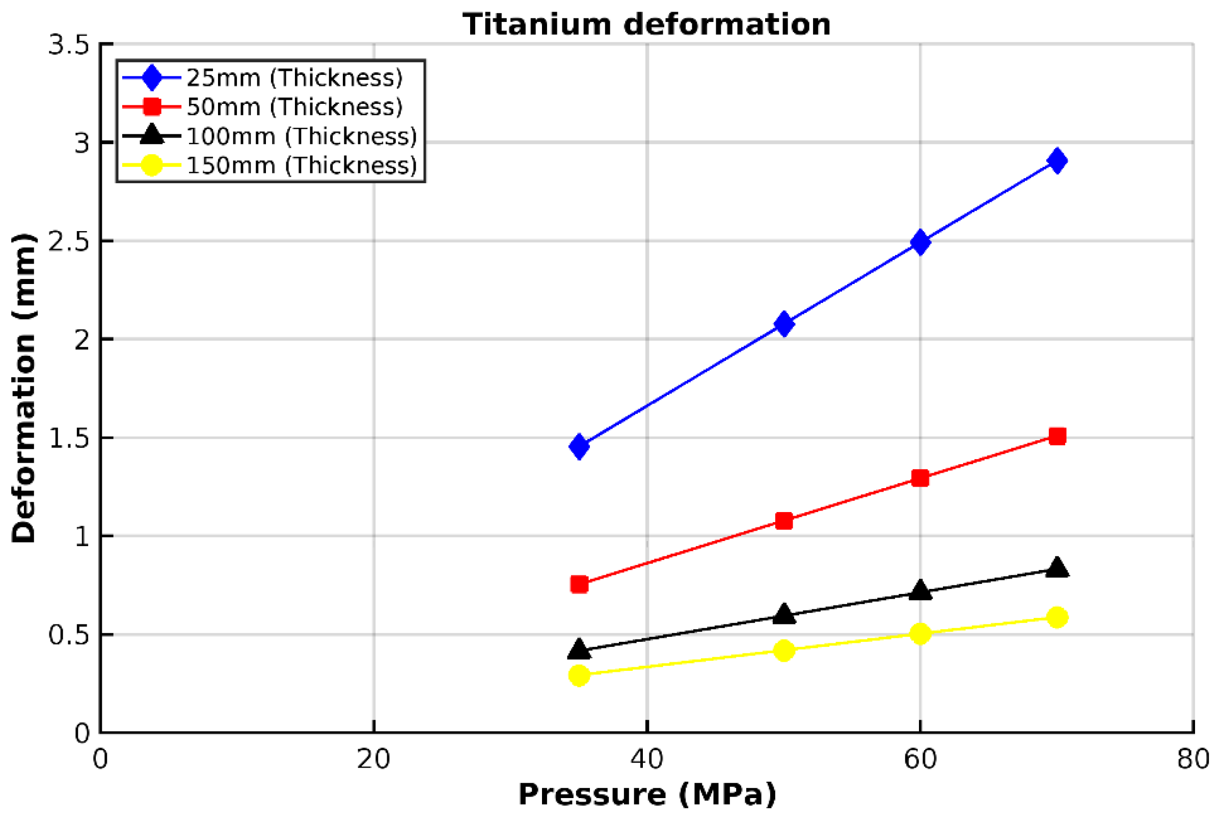
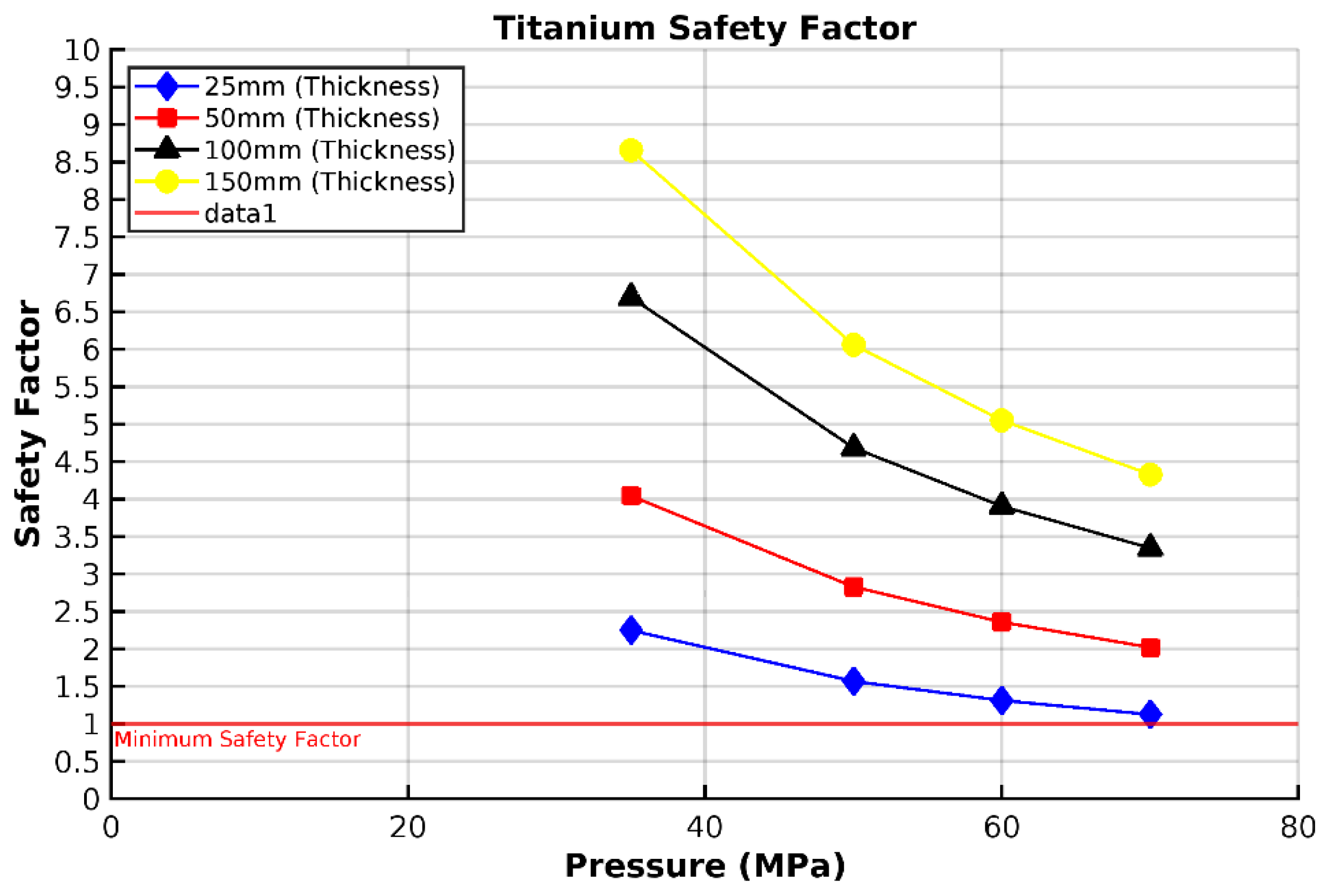
3.3. Analysis of Grade 5 (Ti-6Al-4V) Titanium Vessel
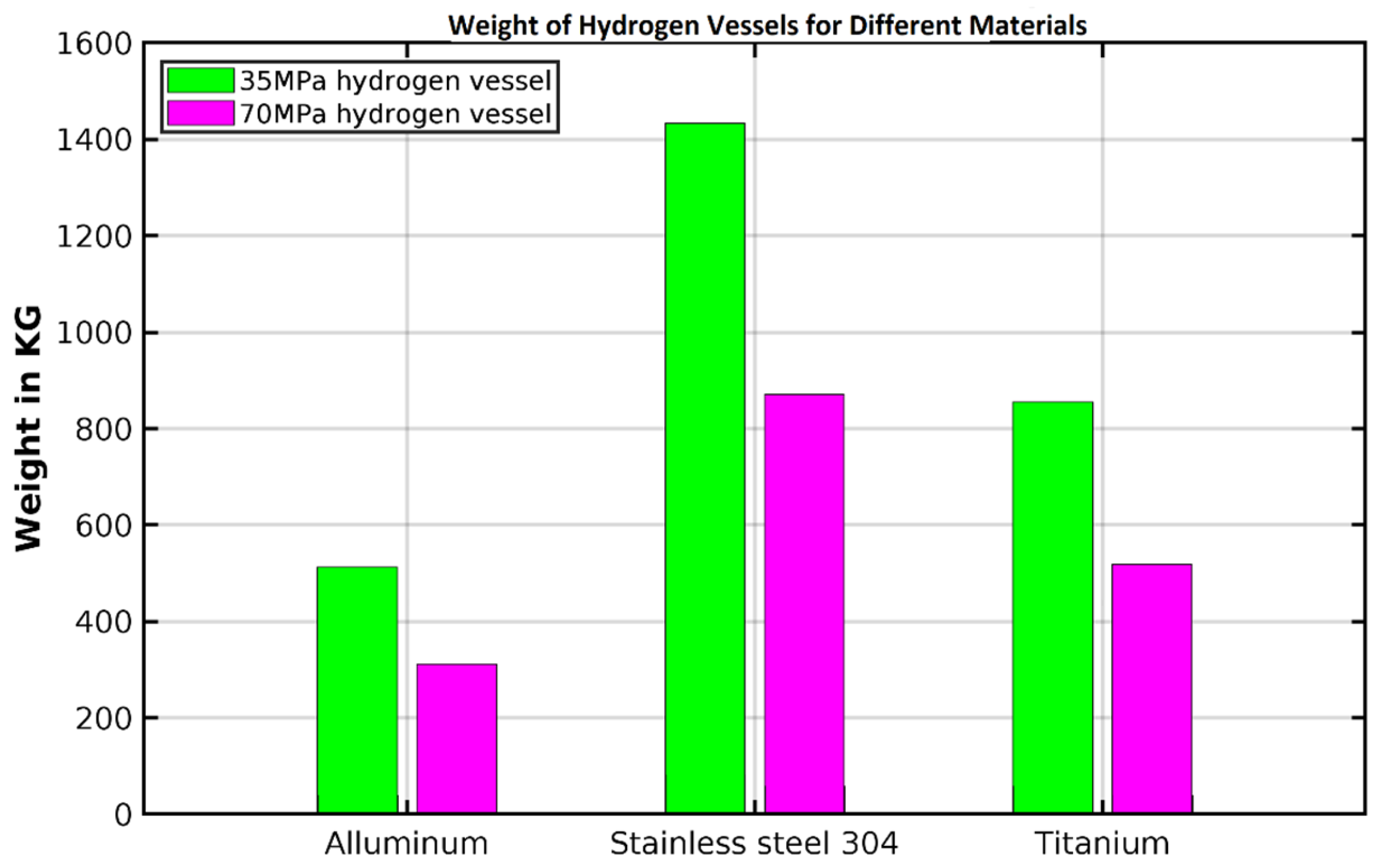
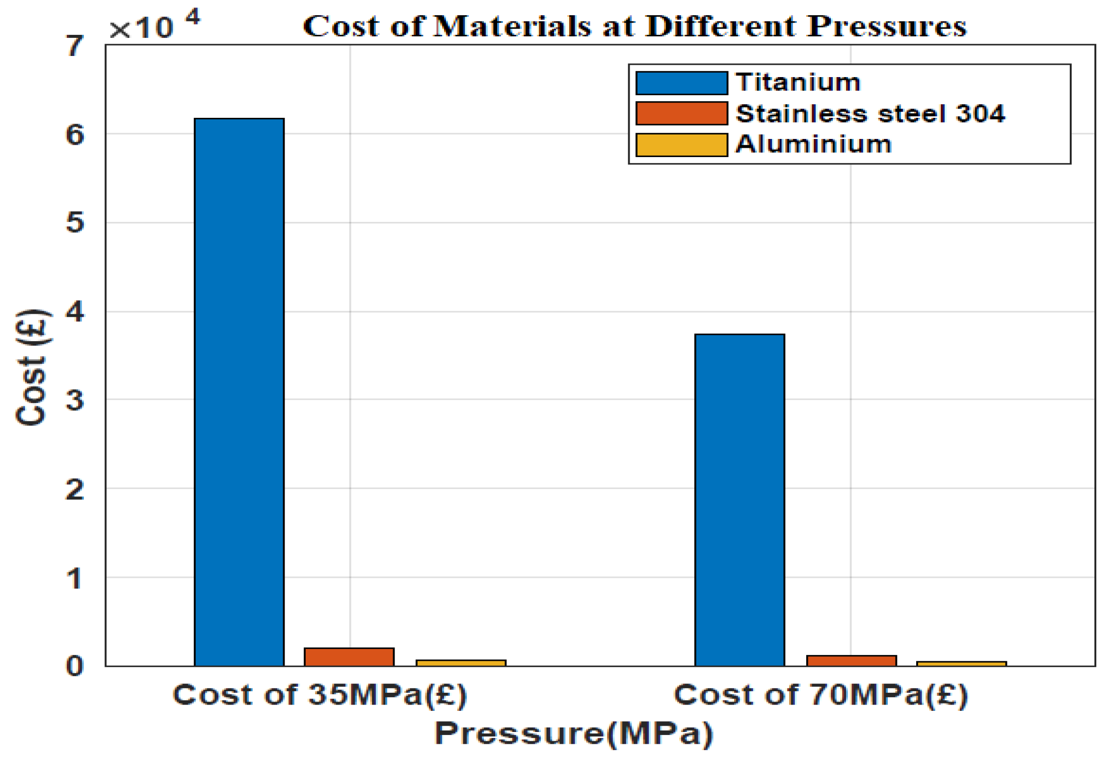
3.4. Weight and Cost Estimation
4. Conclusions
Author Contributions
Funding
Institutional Review Board Statement
Informed Consent Statement
Data Availability Statement
Acknowledgments
Conflicts of Interest
Abbreviations
| H | Height of the vessel (in m) |
| LHV | Lower heating value of hydrogen (33.33 kwh/kg or 120,000 kJ/kg) |
| P | Pressure in MPa |
| P | Power in kW |
| R | Radius of the cylindrical vessel (in m) |
| V | Volume in (m3) |
| ɳ | Efficiency of the fuel cell system |
Appendix A

| 25 mm | 50 mm | 100 mm | 150 mm | |
|---|---|---|---|---|
| 35 MPa | 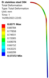 |  | 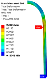 | 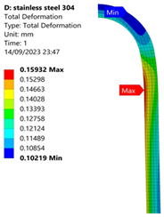 |
| 50 MPa | 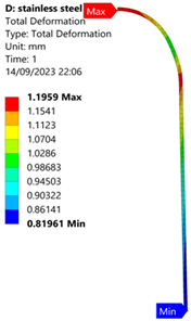 | 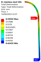 |  | 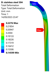 |
| 60 MPa | 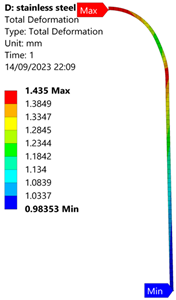 |  |  | 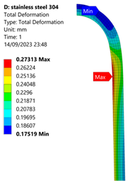 |
| 70 MPa |  | 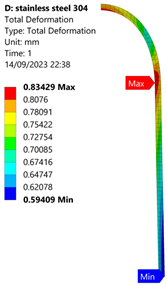 | 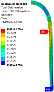 | 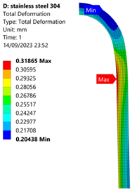 |
| Stainless Steel (304) Hydrogen Vessel (Equivalent Von Mises Stress) | |||
|---|---|---|---|
| 35 MPa | 50 MPa | 60 MPa | 70 MPa |
 |  |  |  |
| 25 mm | 50 mm | 100 mm | 150 mm | |
|---|---|---|---|---|
| 35 MPa | 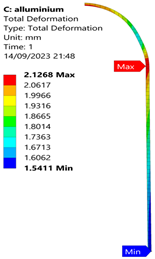 | 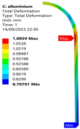 |  | 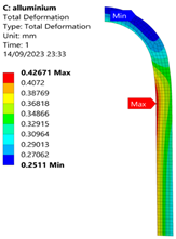 |
| 50 MPa | 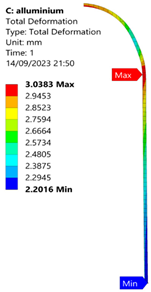 | 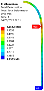 | 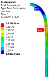 | 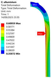 |
| 60 MPa | 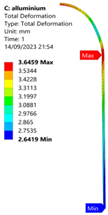 | 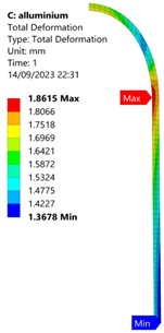 |  |  |
| 70 MPa |  | 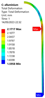 | 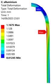 |  |
| Aluminium Hydrogen Vessel (Equivalent Von Mises Stress) | |||
|---|---|---|---|
| 35 MPa | 50 MPa | 60 MPa | 70 MPa |
 |  |  |  |
| 25 mm | 50 mm | 100 mm | 150 mm | |
|---|---|---|---|---|
| 35 MPa | 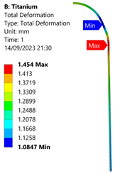 | 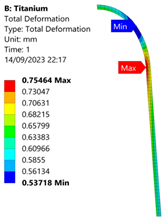 |  |  |
| 50 MPa | 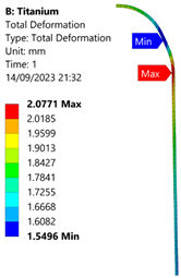 | 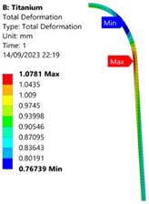 |  | 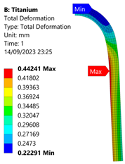 |
| 60 MPa | 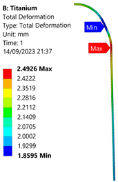 | 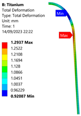 | 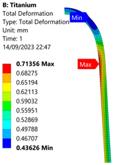 |  |
| 70 MPa | 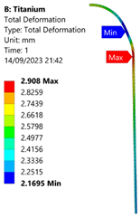 |  | 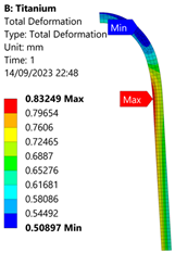 |  |
| Titanium Hydrogen Vessel (Equivalent Von Mises stress) | |||
|---|---|---|---|
| 35 MPa | 50 MPa | 60 MPa | 70 MPa |
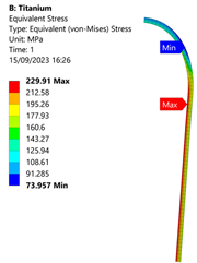 | 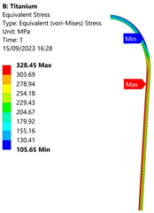 | 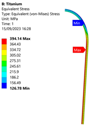 |  |
References
- Baroutaji, A.; Wilberforce, T.; Ramadan, M.; Olabi, A.G. Comprehensive investigation on hydrogen and fuel cell technology in the aviation and aerospace sectors. Renew. Sustain. Energy Rev. 2019, 106, 31–40. [Google Scholar] [CrossRef]
- Bruce, S.; Temminghoff, M.; Hayward, J.; Palfreyman, D.; Munnings, C.; Burke, N.; Creasey, S. Opportunities for Hydrogen in Aviation; CSIRO: Canbera, Australia, 2020.
- Baroutaji, A.; Awotwe, T.W.; Olabi, A.G. Overview of hydrogen and fuel cell technology in the aviation sector. In Proceedings of the 11th International Conference on Sustainable Energy and Environmental Protection, Paisley, UK, 8–11 May 2018. [Google Scholar]
- Sharaf, O.Z.; Orhan, M.F. An overview of fuel cell technology: Fundamentals and applications. Renew. Sustain. Energy Rev. 2014, 32, 810–853. [Google Scholar] [CrossRef]
- Yusaf, T.; Fernandes, L.; Talib, A.R.A.; Altarazi, Y.S.M.; Alrefae, W.; Kadirgama, K.; Ramasamy, D.; Jayasuriya, A.; Brown, G.; Mamat, R.; et al. Sustainable aviation—Hydrogen is the future. Sustainability 2022, 14, 548. [Google Scholar] [CrossRef]
- Hassan, I.A.; Ramadan, H.S.; Saleh, M.A.; Hissel, D. Hydrogen storage technologies for stationary and mobile applications: Review, analysis and perspectives. Renew. Sustain. Energy Rev. 2021, 149, 111311. [Google Scholar] [CrossRef]
- Yılmaz, İ.; İlbaş, M.; Taştan, M.; Tarhan, C. Investigation of hydrogen usage in aviation industry. Energy Convers. Manag. 2012, 63, 63–69. [Google Scholar] [CrossRef]
- Prewitz, M.; Schwärzer, J.; Bardenhagen, A. Potential analysis of hydrogen storage systems in aircraft design. Int. J. Hydrogen Energy 2023, 48, 25538–25548. [Google Scholar] [CrossRef]
- Hordé, T.; Achard, P.; Metkemeijer, R. PEMFC application for aviation: Experimental and numerical study of sensitivity to altitude. Int. J. Hydrogen Energy 2012, 37, 10818–10829. [Google Scholar] [CrossRef]
- Li, C.; Cheng, K.; Ma, S.; Liu, H.; Ji, Z.; Qin, J. Performance analysis of solid oxide fuel cell/piston engine hybrid system for aviation. Appl. Therm. Eng. 2022, 214, 118797. [Google Scholar] [CrossRef]
- Massaro, M.C.; Biga, R.; Kolisnichenko, A.; Marocco, P.; Monteverde, A.H.A.; Santarelli, M. Potential and technical challenges of on-board hydrogen storage technologies coupled with fuel cell systems for aircraft electrification. J. Power Sources 2023, 555, 232397. [Google Scholar] [CrossRef]
- Santin, M.; Traverso, A.; Massardo, A. Technological aspects of gas turbine and fuel cell hybrid systems for aircraft: A review. Aeronaut. J. 2008, 112, 459–467. [Google Scholar] [CrossRef]
- Keim, M.; Kallo, J.; Friedrich, K.A.; Werner, C.; Saballus, M.; Gores, F. Multifunctional fuel cell system in an aircraft environment: An investigation focusing on fuel tank inerting and water generation. Aerosp. Sci. Technol. 2013, 29, 330–338. [Google Scholar] [CrossRef]
- Ayar, M.; Karakoc, T.H. Decision mechanism between fuel cell types: A case study for small aircraft. Int. J. Hydrogen Energy 2023, 48, 23156–23167. [Google Scholar] [CrossRef]
- Arat, H.T.; Sürer, M.G.; Gökpinar, S.; Aydin, K. Conceptual design analysis for a lightweight aircraft with a fuel cell hybrid propulsion system. Energy Sources Part A Recovery Util. Environ. Eff. 2023, 45, 46–60. [Google Scholar] [CrossRef]
- Guida, D.; Minutillo, M. Design methodology for a PEM fuel cell power system in a more electrical aircraft. Appl. Energy 2017, 192, 446–456. [Google Scholar] [CrossRef]
- Kazula, S.; de Graaf, S.; Enghardt, L. Preliminary safety assessment of PEM fuel cell systems for electrified propulsion systems in commercial aviation. In Proceedings of the 32nd European Safety and Reliability Conference (ESREL 2022), Dublin, Ireland, 28 August–1 September 2022; Research Publishing: Singapore, 2022. [Google Scholar]
- Saleh, I.M.; Ali, R.; Zhang, H. Simplified mathematical model of proton exchange membrane fuel cell based on horizon fuel cell stack. J. Mod. Power Syst. Clean Energy 2016, 4, 668–679. [Google Scholar] [CrossRef]
- Saleh, I.; Ali, R.; Zhang, H. Experimental testing and validation of the mathematical model for a self-humidifying PEM fuel cell. J. Mater. Sci. Chem. Eng. 2018, 5, 202–218. [Google Scholar] [CrossRef]
- Schröder, M.; Becker, F.; Kallo, J.; Gentner, C. Optimal operating conditions of PEM fuel cells in commercial aircraft. Int. J. Hydrogen Energy 2021, 46, 33218–33240. [Google Scholar] [CrossRef]
- Hashimoto, S.-i.; Miyata, R.; Kobayashi, K.; Yashiro, K.; Takamura, H.; Yoshimi, K.; Kijima, N.; Manabe, T.; Tsuchiya, T.; Hirota, T.; et al. A new development strategy of light weight solid oxide fuel cells for electrified airplane system. In Proceedings of the 2019 AIAA/IEEE Electric Aircraft Technologies Symposium (EATS), Indianapolis, IN, USA, 22–24 August 2019; pp. 1–6. [Google Scholar]
- Saleh, I.; Ali, R.; Zhang, H. Environmental impact of high altitudes on the operation of PEM fuel cell based UAS. J. Energy Power Eng. 2018, 10, 87–105. [Google Scholar] [CrossRef]
- Wang, B.; Zhao, D.; Li, W.; Wang, Z.; Huang, Y.; You, Y.; Becker, S. Current technologies and challenges of applying fuel cell hybrid propulsion systems in unmanned aerial vehicles. Prog. Aerosp. Sci. 2020, 116, 100620. [Google Scholar] [CrossRef]
- Reid, W.A.; Albayati, I.M. Design of an unmanned aircraft system for high-altitude 1 kW fuel cell power system. Aerosp. Syst. 2021, 4, 353–363. [Google Scholar] [CrossRef]
- Gadalla, M.; Zafar, S. Analysis of a hydrogen fuel cell-PV power system for small UAV. Int. J. Hydrogen Energy 2016, 41, 6422–6432. [Google Scholar] [CrossRef]
- Coutinho, M.; Bento, D.; Souza, A.; Cruz, R.; Afonso, F.; Lau, F.; Suleman, A.; Barbosa, F.R.; Gandolfi, R.; Junior, W.A.; et al. A review on the recent developments in thermal management systems for hybrid-electric aircraft. Appl. Therm. Eng. 2023, 227, 120427. [Google Scholar] [CrossRef]
- Bradley, T.H.; Moffitt, B.A.; Mavris, D.N.; Parekh, D.E. Development and experimental characterization of a fuel cell powered aircraft. J. Power Sources 2007, 171, 793–801. [Google Scholar] [CrossRef]
- Son, H.; Yu, S. Analysis of cooling performance using evaporation enthalpy of product water for a lightweight aviation fuel cell system. Appl. Therm. Eng. 2023, 222, 119937. [Google Scholar] [CrossRef]
- Coppola, C.M.; Tolbatov, I.; Tranca, I.C.; Coletti, C.; Marrone, A.; Storchi, L.; Di Profio, P.; Re, N.; Kazandjian, M.V.; Pellecchia, A.; et al. A database approach for materials selection for hydrogen storage in aerospace technology. Rend. Lincei. Sci. Fis. E Nat. 2019, 30, 287–296. [Google Scholar] [CrossRef]
- Dutczak, J. Liquefied and chemical hydrogen storage in contemporary small drones’ fuel cell propulsion systems. IOP Conf. Ser. Mater. Sci. Eng. 2018, 421, 042015. [Google Scholar] [CrossRef]
- Colozza, A.J.; Kohout, L. Hydrogen Storage for Aircraft Applications Overview; National Aeronautics and Space Administration (NASA) Glenn Research Center: Cleveland, OH, USA, 2002.
- Liu, H.; Qin, J.; Ji, Z.; Guo, F.; Dong, P. Study on the performance comparison of three configurations of aviation fuel cell gas turbine hybrid power generation system. J. Power Sources 2021, 501, 230007. [Google Scholar] [CrossRef]
- Eelman, S.; del Pozo y de Poza, I.; Krieg, T. fuel cell APU’S in commercial aircraft an assessment of SOFC and PEMFC concepts. In Proceedings of the 24th International Congress of the Aeronautical Sciences (ICAS), Yokohama, Japan, 29 August–3 September 2004. [Google Scholar]
- Rajashekara, K.; Grieve, J.; Daggett, D. Solid oxide fuel cell/gas turbine hybrid APU system for aerospace applications. In Proceedings of the Conference Record of the 2006 IEEE Industry Applications Conference Forty-First IAS Annual Meeting, Tampa, FL, USA, 8–12 October 2006; IEEE: New York, NY, USA, 2006; Volume 5, pp. 2185–2192. [Google Scholar]
- Marine Service Noord. How Much Hydrogen Do I Need For The Fuel Cell On My Ship? Available online: https://marine-service-noord.com/en/products/alternative-fuels-and-technologies/hydrogen/how-much-hydrogen-do-i-need/#:~:text=With%20these%20values%20%E2%80%8B%E2%80%8B,kg%20of%20hydrogen%20is%20required (accessed on 1 August 2023).
- Salah, I.M. Modelling, Simulation and Performance Evaluation: PEM Fuel Cells for High Altitude UAS. Ph.D. Thesis, Sheffield Hallam University, Sheffield, UK, 2015. [Google Scholar]
- Rievaj, V.; Gaňa, J.; Synák, F. Is hydrogen the fuel of the future? Transp. Res. Procedia 2019, 40, 469–474. [Google Scholar] [CrossRef]
- HPBS. International GHG Calculating Methodology Standards. Available online: https://hpb-s.com/en/news/international-ghg-calculating-methodology-standards/ (accessed on 1 August 2023).
- OpenAirlines. How to Track Your APU Fuel Burn on Ground? Available online: https://blog.openairlines.com/how-to-track-apu-fuel-burn-on-ground#:~:text=Some%20tips%20to%20reduce%20your%20APU%20fuel%20burn&text=According%20to%20United%20Continental%2C%20APU,GPU%20when%20it%20is%20possible (accessed on 1 August 2023).

| Material Properties | Grade 5 (Ti-6Al-4V) Titanium | 304 Stainless Steel | 6061-T6 Aluminium |
|---|---|---|---|
| Density | 4620 Kg m−3 | 7750 Kg m−3 | 2770 Kg m−3 |
| Young’s modulus | 9.6 × 10¹⁰ Pa | 1.93 × 10¹¹ Pa | 7.1 × 10¹⁰ Pa |
| Poisson’s ratio | 0.36 | 0.31 | 0.33 |
| Tensile yield strength | 930 MPa | 207 MPa | 280 MPa |
| Compressive yield strength | 930 MPa | 207 MPa | 280 MPa |
| Tensile ultimate strength | 1070 MPa | 586 MPa | 310 MPa |
Disclaimer/Publisher’s Note: The statements, opinions and data contained in all publications are solely those of the individual author(s) and contributor(s) and not of MDPI and/or the editor(s). MDPI and/or the editor(s) disclaim responsibility for any injury to people or property resulting from any ideas, methods, instructions or products referred to in the content. |
© 2025 by the authors. Licensee MDPI, Basel, Switzerland. This article is an open access article distributed under the terms and conditions of the Creative Commons Attribution (CC BY) license (https://creativecommons.org/licenses/by/4.0/).
Share and Cite
Antony Ramesh, A.N.; Aliyu, A.M.; Tucker, N.; Albayati, I.M. Hydrogen Storage Vessel for a Proton-Exchange Membrane (PEM) Fuel Cell Auxiliary Power Unit for Commercial Aircraft. Appl. Sci. 2025, 15, 8006. https://doi.org/10.3390/app15148006
Antony Ramesh AN, Aliyu AM, Tucker N, Albayati IM. Hydrogen Storage Vessel for a Proton-Exchange Membrane (PEM) Fuel Cell Auxiliary Power Unit for Commercial Aircraft. Applied Sciences. 2025; 15(14):8006. https://doi.org/10.3390/app15148006
Chicago/Turabian StyleAntony Ramesh, Anto Nickhil, Aliyu M. Aliyu, Nick Tucker, and Ibrahim M. Albayati. 2025. "Hydrogen Storage Vessel for a Proton-Exchange Membrane (PEM) Fuel Cell Auxiliary Power Unit for Commercial Aircraft" Applied Sciences 15, no. 14: 8006. https://doi.org/10.3390/app15148006
APA StyleAntony Ramesh, A. N., Aliyu, A. M., Tucker, N., & Albayati, I. M. (2025). Hydrogen Storage Vessel for a Proton-Exchange Membrane (PEM) Fuel Cell Auxiliary Power Unit for Commercial Aircraft. Applied Sciences, 15(14), 8006. https://doi.org/10.3390/app15148006