
Optimised Twin Fluid Atomiser Design for High-Viscosity, Shear-Thinning Fluids


Abstract
1. Introduction
2. Materials and Methods
2.1. Model Fluid and Atomising Agent Properties
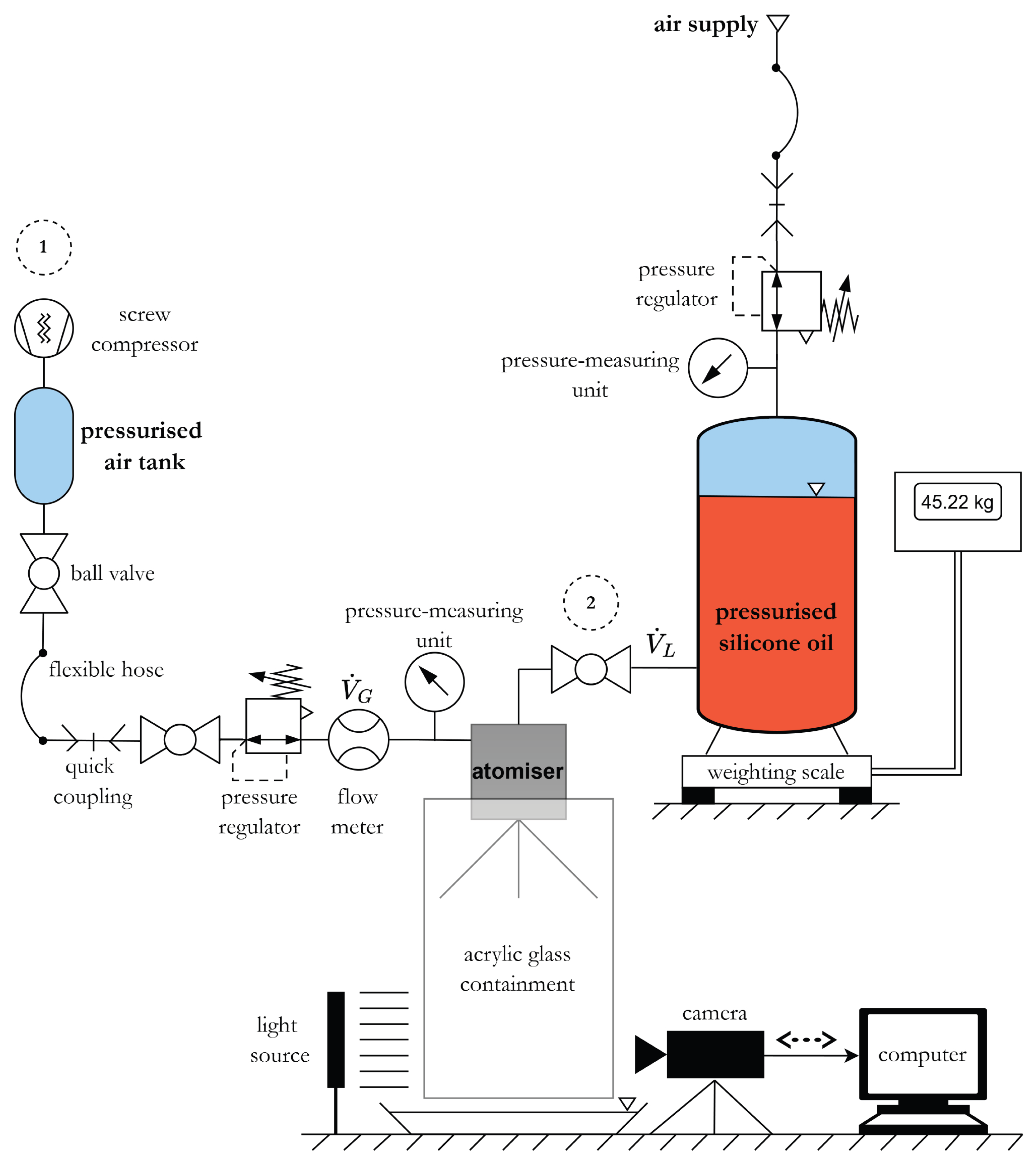
2.2. Setup
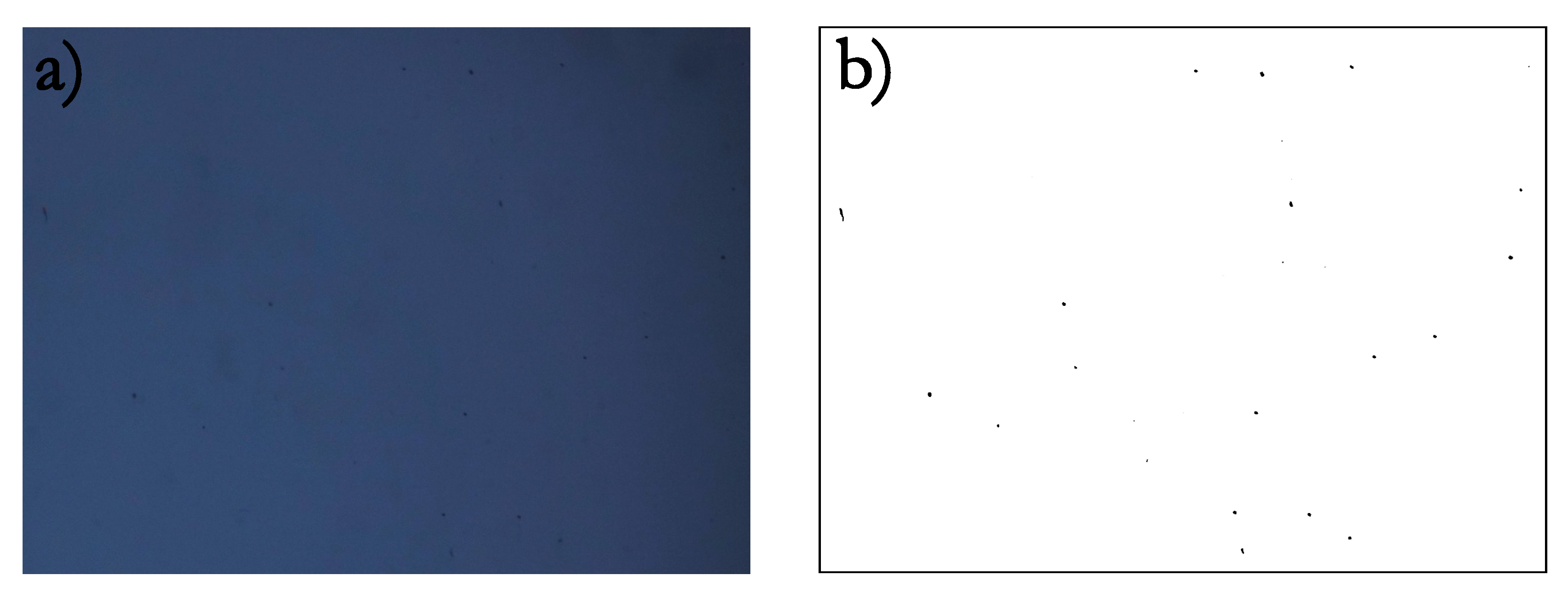
2.3. Video Analysis
2.4. Image Analysis
3. Results
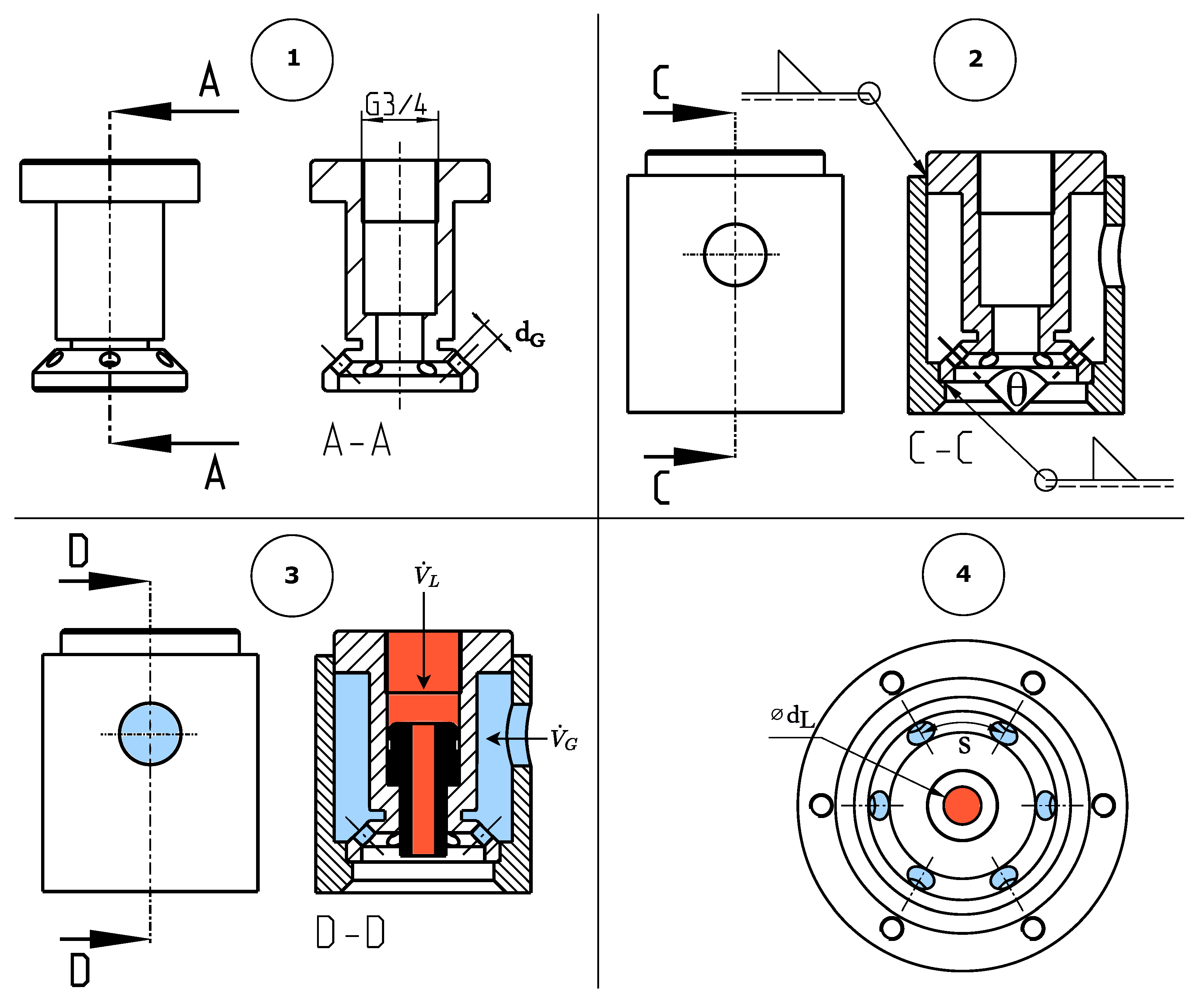
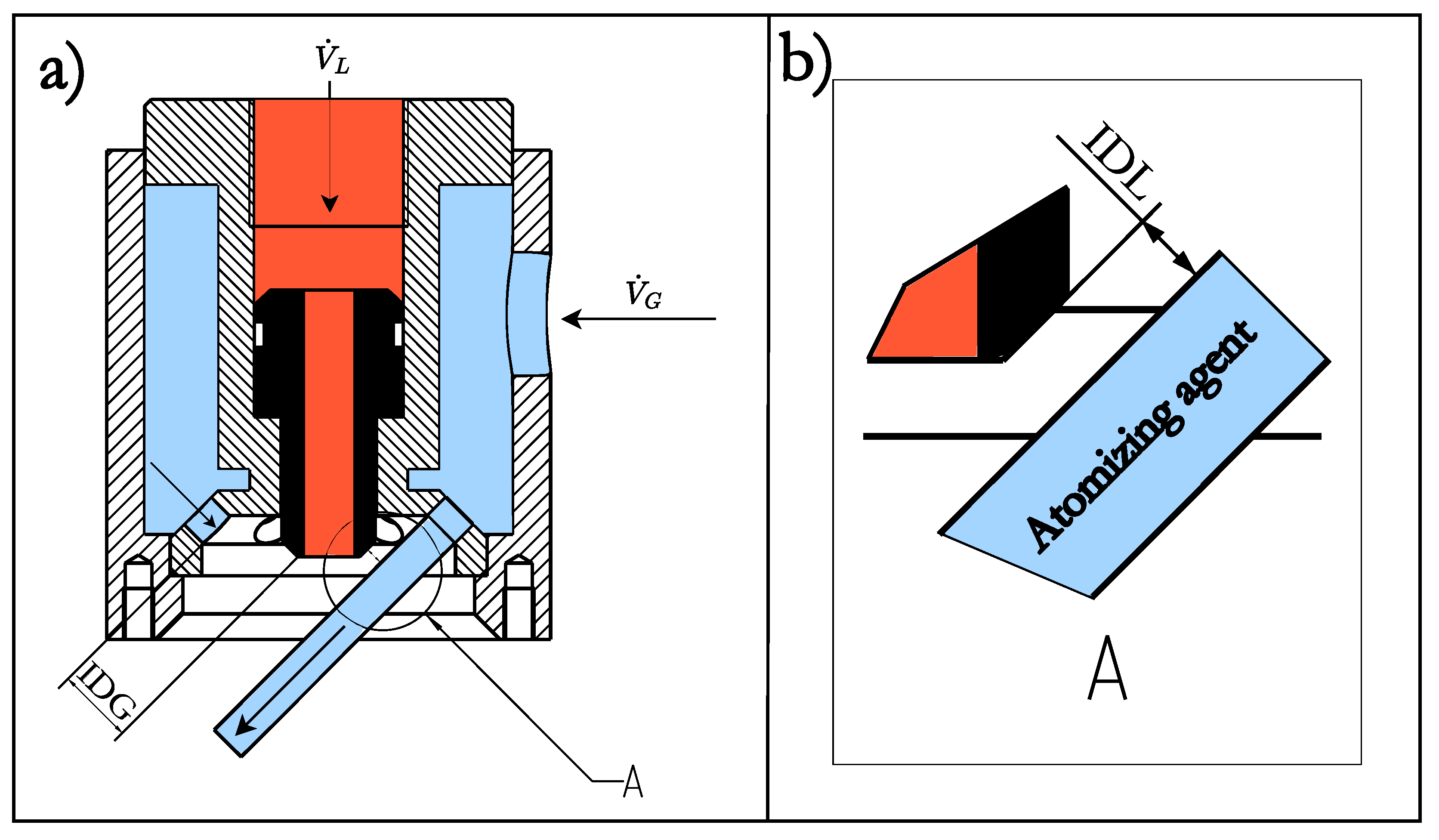
3.1. Nozzle Inserts
3.2. Nozzle Configurations
3.3. Droplet Velocity
3.4. ALR
3.5. Atomisation Quality
4. Conclusions
Author Contributions
Funding
Institutional Review Board Statement
Informed Consent Statement
Data Availability Statement
Acknowledgments
Conflicts of Interest
Nomenclature
| Abbreviations | |
| CWS | Coal–water slurry |
| DS | Dataset |
| MP | Measurement point |
| NC | Nozzle configuration |
| ONC | Optimal nozzle configuration |
| PDMS | Polydimethylsiloxane |
| Subscripts | |
| A | Ambient |
| G | Gas |
| L | Liquid |
| Variables | |
| Change in mass, kg | |
| Change in time, s | |
| Velocity difference between gas jet and liquid stream, m s−1 | |
| Mass flow rate, kg s−1 | |
| ALR = air-liquid ratio, - | |
| Volumetric flow rate of liquid, m3 s−1 | |
| Standard volumetric flow rate of gas, std m3/s | |
| Viscosity at specified shear rate, Pa s | |
| Shear rate, s−1 | |
| Density, kg m−3 | |
| Surface tension, N m−1 | |
| Geometrical apex angle of atomising agent, ° | |
| Area ratio of gas nozzle holes to liquid tube cross-section, - | |
| Axial offset between atomiser and image acquisition location, m | |
| D | Characteristic droplet length scale, m |
| Diameter of gas nozzle orifices, m | |
| Diameter of a circle with the same area as droplet i, m | |
| Diameter of nozzle insert, m | |
| Sauter mean diameter, m | |
| Viscous energy dissipation, kgm2/s2 | |
| Surface energy, kgm2/s2 | |
| Frames per second, s−1 | |
| Impingement distance: gas, m | |
| Impingement distance: liquid, m | |
| Mach number, - | |
| n | Number of gas orifices, - |
| Ohnesorge number, - | |
| p | Static pressure, Pa |
| Reynolds number, - | |
| s | Circumferential distance between two adjacent gas nozzle holes, m |
| T | Temperature, K |
| Weber number, - |
References
- Sichler, T.C.; Adam, C.; Montag, D.; Barjenbruch, M. Future nutrient recovery from sewage sludge regarding three different scenarios—German case study. J. Clean. Prod. 2022, 333, 130130. [Google Scholar] [CrossRef]
- Adam, C.; Peplinski, B.; Michaelis, M.; Kley, G.; Simon, F.G. Thermochemical treatment of sewage sludge ashes for phosphorus recovery. Waste Manag. 2009, 29, 1122–1128. [Google Scholar] [CrossRef] [PubMed]
- Wang, Y.; Yu, L.; Yuan, H.; Ying, D.; Zhu, N. Improved removal of phosphorus from incinerated sewage sludge ash by thermo-chemical reduction method with CaCl2 application. J. Clean. Prod. 2020, 258, 120779. [Google Scholar] [CrossRef]
- Xu, H.; Wang, C.; Wang, K. Full-Scale Plant Study of the Innovative Spray-Drying-Based Sludge Incineration (SDSI) Process: Behavior of Heavy Metals. Energy Fuels 2015, 29, 3908–3912. [Google Scholar] [CrossRef]
- Gvozdyakov, D.; Zenkov, A.; Lavrinenko, S.; Marysheva, Y.; Larionov, K. Spraying Characteristics of Alcohol–Coal–Water Slurries with Low Coal Content. Chem. Eng. Technol. 2022, 45, 936–945. [Google Scholar] [CrossRef]
- Deng, J.; Ding, Z.; Zhou, H.; Tan, Y. Performance and wear characteristics of ceramic, cemented carbide, and metal nozzles used in coal–water–slurry boilers. Int. J. Refract. Met. Hard Mater. 2009, 27, 919–926. [Google Scholar] [CrossRef]
- Lefebvre, A.H.; McDonell, V.G. Atomization and Sprays, 2nd ed.; CRC Press: Boca Raton, FL, USA, 2017. [Google Scholar]
- Gvozdyakov, D.; Zenkov, A. Nozzles for Spraying Coal–Water Fuels. Appl. Sci. 2023, 13, 12006. [Google Scholar] [CrossRef]
- Kuznetsov, G.V.; Strizhak, P.A.; Valiullin, T.R.; Volkov, R.S. Atomization behavior of composite liquid fuels based on typical coal processing wastes. Fuel Process. Technol. 2022, 225, 107037. [Google Scholar] [CrossRef]
- Wu, X.; Guo, Q.; Gong, Y.; Liu, J.; Luo, X.; Wu, T.; Yu, G. Influence of burner geometry on atomization of coal water slurry in an entrained-flow gasifier. Chem. Eng. Sci. 2022, 247, 117088. [Google Scholar] [CrossRef]
- Zheng, J.; Xu, Y.; Wang, Q.; He, H. Characteristics of particle size and velocity of droplets of coal water slurry subjected to air-blast electrostatic atomization using a phase Doppler particle analyzer. J. Electrost. 2019, 98, 40–48. [Google Scholar] [CrossRef]
- Daviault, S.G.; Ramadan, O.B.; Matida, E.A.; Hughes, P.M.; Hughes, R. Atomization performance of petroleum coke and coal water slurries from a twin fluid atomizer. Fuel 2012, 98, 183–193. [Google Scholar] [CrossRef]
- Taboada, M.L.; Zapata, E.; Karbstein, H.P.; Gaukel, V. Investigation of Oil Droplet Breakup during Atomization of Emulsions: Comparison of Pressure Swirl and Twin-Fluid Atomizers. Fluids 2021, 6, 219. [Google Scholar] [CrossRef]
- Shadrin, E.; Anufriev, I.S.; Butakov, E.B.; Kopyev, E.P.; Alekseenko, S.V.; Maltsev, L.I.; Sharypov, O.V. Coal-water slurry atomization in a new pneumatic nozzle and combustion in a low-power industrial burner. Fuel 2021, 303, 121182. [Google Scholar] [CrossRef]
- Aliseda, A.; Hopfinger, E.J.; Lasheras, J.C.; Kremer, D.M.; Berchielli, A.; Connolly, E.K. Atomization of viscous and non-newtonian liquids by a coaxial, high-speed gas jet. Experiments and droplet size modeling. Int. J. Multiph. Flow 2008, 34, 161–175. [Google Scholar] [CrossRef]
- Ghezelchi, M.H.; Garcia-Perez, M.; Wu, H. Bioslurry as a Fuel. 7: Spray Characteristics of Bio-Oil and Bioslurry via Impact and Twin-Fluid Atomizers. Energy Fuels 2015, 29, 8058–8065. [Google Scholar] [CrossRef]
- Loureiro, L.; Gil, P.; Vieira de Campos, F.V.; Nunes, L.; Ferreira, J. Dispersion and flow properties of charcoal oil slurries (ChOS) as potential renewable industrial liquid fuels. J. Energy Inst. 2018, 91, 978–983. [Google Scholar] [CrossRef]
- Cheng, Y.; Li, H. Rheological behavior of sewage sludge with high solid content. Water Sci. Technol. A J. Int. Assoc. Water Pollut. Res. 2015, 71, 1686–1693. [Google Scholar] [CrossRef] [PubMed]
- Gienau, T.; Kraume, M.; Rosenberger, S. Rheological Characterization of Anaerobic Sludge from Agricultural and Bio–Waste Biogas Plants. Chem. Ing. Tech. 2018, 90, 988–997. [Google Scholar] [CrossRef]
- Hu, S.; Liu, L.; Yang, X.; Li, J.; Zhou, B.; Wu, C.; Weng, L.; Liu, K. Influence of different dispersants on rheological behaviors of coal water slurry prepared from a low quality coal. RSC Adv. 2019, 9, 32911–32921. [Google Scholar] [CrossRef] [PubMed]
- Ou, H.; Su, L.; Shi, Y.; Ruan, S. Investigation on High-Viscosity Chemical Waste Liquid Atomizer Based on VOF-DPM. Energies 2023, 16, 3109. [Google Scholar] [CrossRef]
- Cao, X.; Pan, Y.; Jiang, K.; Zhu, K.; Ren, X. Effect of high-temperature thermal hydrolysis on rheological properties and dewaterability of sludge. Environ. Technol. 2021, 42, 3707–3715. [Google Scholar] [CrossRef] [PubMed]
- Taburchinov, R.I.; Belonogov, M.V.; Egorov, R.I. Effect of the Addition of Petrochemicals onto the Atomization and Ignition of the Coal-Water Slurry Prepared from the Wastes. Appl. Sci. 2020, 10, 8574. [Google Scholar] [CrossRef]
- Ling, W.; Xing, Y.; Hong, C.; Zhao, C.; Wang, Y. Experiment study on particle pulverization-assisted convective air drying of sewage sludge. Dry. Technol. 2024, 42, 1509–1525. [Google Scholar] [CrossRef]
- Xiao, J.; Wang, S.; Duan, X.; Ye, S.; Wen, J.; Zhang, Z. Rheological models for temperature and concentration dependencies of coal water slurry. Int. J. Coal Prep. Util. 2022, 42, 1185–1203. [Google Scholar] [CrossRef]
- Eshtiaghi, N.; Markis, F.; Yap, S.D.; Baudez, J.C.; Slatter, P. Rheological characterisation of municipal sludge: A review. Water Res. 2013, 47, 5493–5510. [Google Scholar] [CrossRef] [PubMed]
- Wolski, P. Rheological properties of disintegrated sewage sludge. E3S Web Conf. 2017, 22, 00189. [Google Scholar] [CrossRef]
- Wacker Siliconöle. 2001. Available online: www.hellermanntyton.at/binaries/content/assets/downloads/at/datenblatter/01-wacker-silikone/siliconefluidsakde.pdf (accessed on 17 June 2025).
- ShinEtsu Silicone Oil Performance Test Results. 2014. Available online: www.shinetsusilicone-global.com/catalog/pdf/kf96_e.pdf (accessed on 12 July 2025).
- Bayer Silicones. 2020. Available online: https://dcproducts.com.au/wp-content/uploads/2020/12/BayerBaysiloneFluidsBrochure.pdf (accessed on 12 July 2025).
- Yule, A.J. Atomization of Melts: For Powder Production and Spray Deposition, 1st ed.; Oxford University Press Inc.: Oxford, UK, 1994; Chapter 2. [Google Scholar]
- Wang, P.; Zhou, X.L.; Li, X.G.; Chen, Z.P.; Hu, Q.P.; Wang, X.; Yu, Z.Y. Numerical and experimental investigation of close-coupled twin-nozzle gas atomization towards fine high-entropy alloy powder production. J. Mater. Process. Technol. 2024, 324, 118238. [Google Scholar] [CrossRef]
- Zhang, M.; Zhang, Z.; Liu, Q. Research Advances in Close-Coupled Atomizer Flow and Atomizing Mechanisms. Powder Metall. Met. Ceram. 2023, 62, 400–426. [Google Scholar] [CrossRef]
- Qing, Y.; Guo, K.; Liu, C.; Qin, Y.; Zhan, Y.; Shuo, S.; Wei, Y.; Yu, B.; Liu, C. Impact of Atomization Pressure on the Particle Size of Nickel-Based Superalloy Powders by Numerical Simulation. Materials 2022, 15, 3020. [Google Scholar] [CrossRef] [PubMed]
- Sänger, A.D. Zerstäubung Hochviskoser Fluide bei Variierendem Systemdruck: Grundlagenforschung zur Hochdruck-Flugstromvergasung. Doctoral Dissertation, Institut für Technische Chemie (ITC), Karlsruhe, Germany, 2018. [Google Scholar] [CrossRef]
- Mandal, S.; Sadeghianjahromi, A.; Wang, C.C. Experimental and numerical investigations on molten metal atomization techniques—A critical review. Adv. Powder Technol. 2022, 33, 103809. [Google Scholar] [CrossRef]
- Cheng, T.; Leibovici, R.; Kong, B.; van Hout, R. Experimental investigation of primary breakup in close-coupled gas atomization. Int. J. Multiph. Flow 2024, 181, 105009. [Google Scholar] [CrossRef]
- Lefebvre, A.H. Energy Considerations in Twin-Fluid Atomization. In Proceedings of the ASME 1990 International Gas Turbine and Aeroengine Congress and Exposition. Volume 3: Coal, Biomass and Alternative Fuels; Combustion and Fuels; Oil and Gas Applications, Cycle Innovations, Brussels, Belgium, 11–14 June 1990. [Google Scholar] [CrossRef]
- Motaman, S.; Mullis, A.M.; Cochrane, R.F.; Borman, D.J. Numerical and Experimental Investigations of the Effect of Melt Delivery Nozzle Design on the Open- to Closed-Wake Transition in Closed-Coupled Gas Atomization. Metall. Mater. Trans. B 2015, 46, 1990–2004. [Google Scholar] [CrossRef]
- Dieter Rist. Dynamik Realer Gase: Grundlagen, Berechnungen und Daten für Thermogasdynamik, Strömungsmechanik und Gastechnik; Springer: Berlin/Heidelberg, Germany, 1996; Chapter 16. [Google Scholar] [CrossRef]
- Venczel, M.; Bognár, G.; Veress, Á. Temperature-Dependent Viscosity Model for Silicone Oil and Its Application in Viscous Dampers. Processes 2021, 9, 331. [Google Scholar] [CrossRef]
- Li, X.; Gao, H.; Soteriou, M.C. Investigation of the impact of high liquid viscosity on jet atomization in crossflow via high-fidelity simulations. Phys. Fluids 2017, 29, 082103. [Google Scholar] [CrossRef]


| Fluid | T K | Nm−1 | Pa s | kgm−3 | WeL/ReL - | - |
|---|---|---|---|---|---|---|
| Water | 298 | 72 | 0.00089 | 997 | 4 | 5 |
| Sewage Sludge | 298 | 40 | 2.2 | 1100 | 16,500 | 14,832 |
| Silicone oil | 298 | 21.4 | 2 | 970 | 28,037 | 19,631 |
K | Pa s | kgm−3 | Nm−1 |
|---|---|---|---|
| 273 | 17.3 | 992 | - |
| 278 | 15.5 | 988 | - |
| 283 | 13.7 | 984 | - |
| 288 | 12.3 | 980 | - |
| 293 | 11.1 | 975 | - |
| 298 | 9.7 | 970 | 21.5 |
| NC | n - | m | θ ° | - | - |
|---|---|---|---|---|---|
| No. 1 | 3 | 8 | 90 | 3 | 4.65 |
| No. 2 | 4 | 7 | 90 | 3.06 | 3.98 |
| No. 3 | 6 | 6 | 60 | 3.38 | 3.1 |
| No. 4 | 6 | 6 | 90 | 3.38 | 3.1 |
| No. 5 | 6 | 6 | 120 | 3.38 | 3.1 |
| No. 6 | 8 | 5 | 90 | 3.13 | 2.79 |
| No. 7 | 10 | 4.5 | 90 | 3.16 | 2.48 |
| No. 8 | 12 | 4 | 90 | 3 | 2.32 |
| No. 9 | 24 | 3 | 30 | 3.38 | 1.55 |
| No. 10 | 24 | 3 | 90 | 3.38 | 1.55 |
| Index Figure 6 | NC | FPS s−1 | Pa s | ALR - | std m3/s | kgs−1 |
|---|---|---|---|---|---|---|
| 1 | 4 | 60 | 11.1 | 3849 | 83.33 | 21.00 |
| 2 | 4 | 5000 | 11.1 | 4875 | 105.56 | 21.00 |
| 3 | 4 | 10,000 | 11.1 | 6143 | 52.78 | 8.33 |
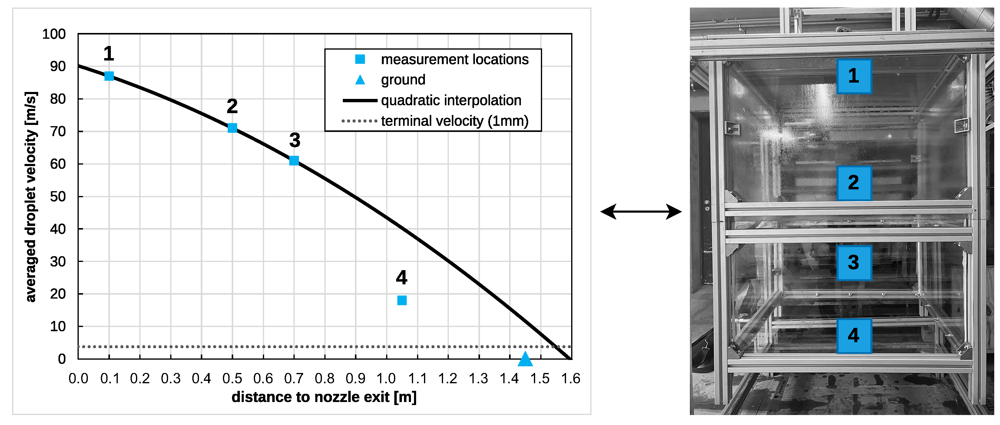
| NC | MP | AX m × 103 | ALR - | Avg. Velocity ms−1 | Std. Velocity ms−1 |
|---|---|---|---|---|---|
| No. 4 | 1 | 100 (12.5 × ) | 12,286 | 86.2 | 29.6 |
| No. 4 | 2 | 500 (62.5 × ) | 12,286 | 71.1 | 24.3 |
| No. 4 | 3 | 700 (87.5 × ) | 12,286 | 61.3 | 24.6 |
| No. 4 | 4 | 1050 (131.25 × ) | 12,286 | 14.8 | 6.8 |
| NC | std m3/s | K | Ma - | Pa |
|---|---|---|---|---|
| No. 4 | 52.78 | 298 | 0.9 | 1 |
| No. 4 | 105.56 | 288 | 1.0 | 1.8 |
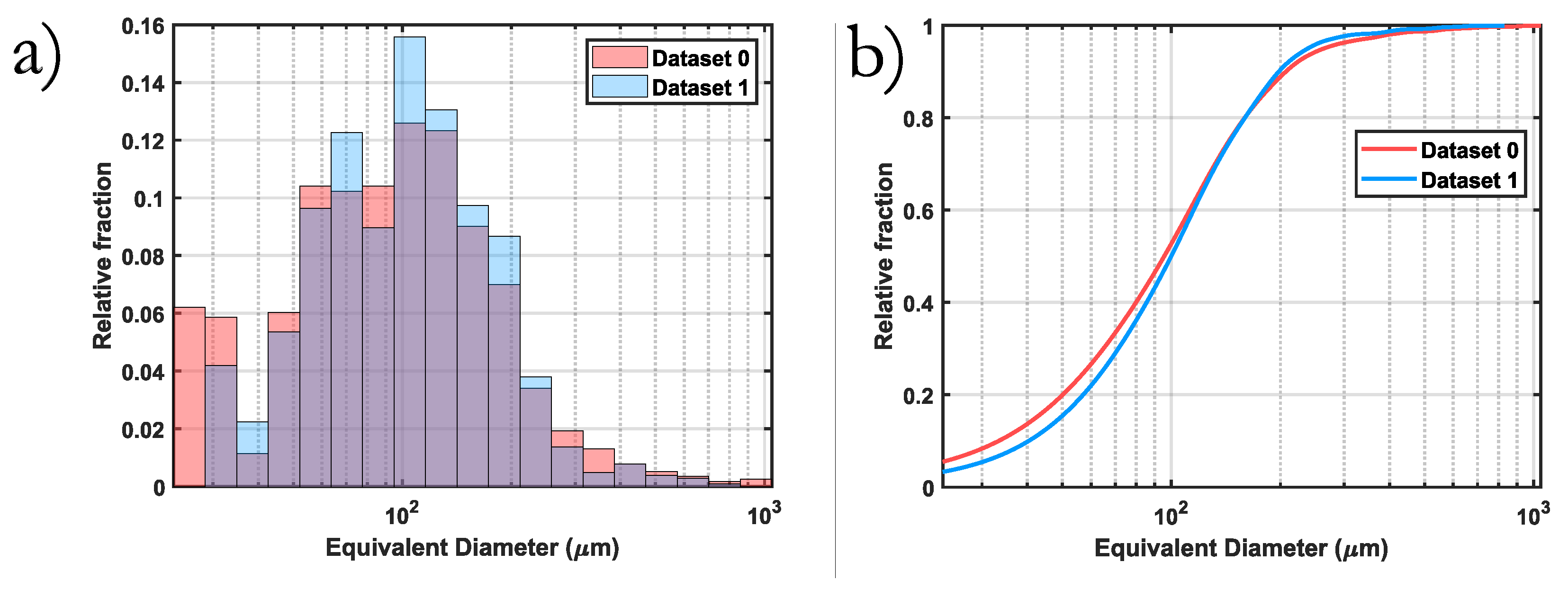
| DS | NC | AX m | Pa s | ALR - | kgs−1 | × m |
|---|---|---|---|---|---|---|
| 0 | 4 | 62.5 × | 12.3 | 12,286 | 8.33 | 367 |
| 1 | 4 | 131.25 × | 12.3 | 12,286 | 8.33 | 259 |
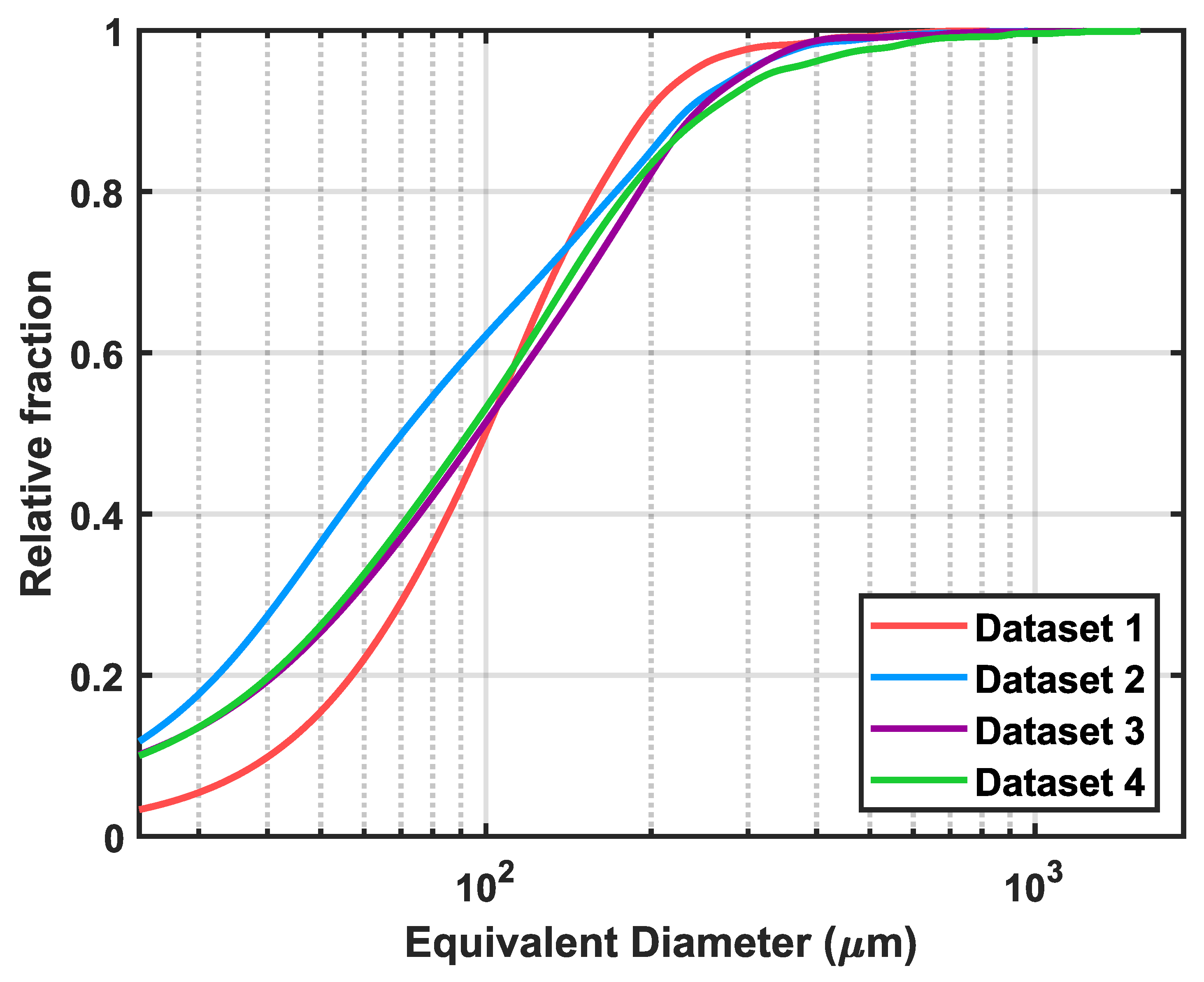
| DS | NC | AX m | Pa s | ALR - | × kgs−1 | × m |
|---|---|---|---|---|---|---|
| 0 | 4 | 62.5 × | 12.3 | 12,286 | 8.33 | 367 |
| 1 | 4 | 131.25 × | 12.3 | 12,286 | 8.33 | 259 |
| 2 | 4 | 131.25 × | 16.7 | 20,477 | 5.00 | 343 |
| 3 | 4 | 131.25 × | 15.9 | 11,376 | 9.00 | 372 |
| 4 | 4 | 131.25 × | 15.9 | 8532 | 12.00 | 570 |
Disclaimer/Publisher’s Note: The statements, opinions and data contained in all publications are solely those of the individual author(s) and contributor(s) and not of MDPI and/or the editor(s). MDPI and/or the editor(s) disclaim responsibility for any injury to people or property resulting from any ideas, methods, instructions or products referred to in the content. |
© 2025 by the authors. Licensee MDPI, Basel, Switzerland. This article is an open access article distributed under the terms and conditions of the Creative Commons Attribution (CC BY) license (https://creativecommons.org/licenses/by/4.0/).
Share and Cite
Diamantopoulos, M.; Hochenauer, C. Optimised Twin Fluid Atomiser Design for High-Viscosity, Shear-Thinning Fluids. Appl. Sci. 2025, 15, 7992. https://doi.org/10.3390/app15147992
Diamantopoulos M, Hochenauer C. Optimised Twin Fluid Atomiser Design for High-Viscosity, Shear-Thinning Fluids. Applied Sciences. 2025; 15(14):7992. https://doi.org/10.3390/app15147992
Chicago/Turabian StyleDiamantopoulos, Marvin, and Christoph Hochenauer. 2025. "Optimised Twin Fluid Atomiser Design for High-Viscosity, Shear-Thinning Fluids" Applied Sciences 15, no. 14: 7992. https://doi.org/10.3390/app15147992
APA StyleDiamantopoulos, M., & Hochenauer, C. (2025). Optimised Twin Fluid Atomiser Design for High-Viscosity, Shear-Thinning Fluids. Applied Sciences, 15(14), 7992. https://doi.org/10.3390/app15147992