1. Introduction
With the rapid development of intelligent robotics technology and the Beidou Satellite Navigation System (BDS), autonomous mobile robots based on high-precision positioning have been widely used in industrial inspection, smart logistics, autonomous driving, and other fields. Especially in the power industry, the demand for automated substation inspection has been increasing [
1,
2]. Robots replacing humans in high-voltage equipment inspection, fault detection, and maintenance has become a trend. Through high-precision navigation and positioning technology, mobile robots can efficiently complete autonomous path planning and navigation tasks, greatly improving operational efficiency and reducing labor costs. The Beidou Navigation Satellite System (BDS), particularly its third generation (BDS-3), has been providing global Positioning, Navigation, and Timing (PNT) services since 2020 [
3]. Unlike other Global Navigation Satellite Systems (GNSSs), such as GPS (USA), GLONASS (Russia), and Galileo (EU), BDS utilizes a unique hybrid constellation of Geostationary Earth Orbit (GEO), Inclined Geosynchronous Orbit (IGSO), and Medium Earth Orbit (MEO) satellites. This architecture provides enhanced coverage and accuracy in the Asia–Pacific region, making it particularly suitable for applications within China [
4]. While our proposed fusion framework is applicable to other GNSSs, this study focuses on BDS due to its regional performance advantages and its strategic importance for critical national infrastructure like the power grid. However, the unique characteristics of substation environments present severe challenges for the application of high-precision navigation systems [
5,
6,
7].
Substation environments pose severe challenges for high-precision navigation. The dense arrangement of high-voltage equipment generates strong electromagnetic interference that degrades satellite signal quality [
8,
9,
10]. Concurrently, metal structures and buildings cause significant signal obstruction and multipath effects. The complex layout of these environments, with narrow passages and dynamic obstacles, further complicates autonomous navigation, rendering global positioning from Beidou alone insufficient for safe and reliable operation [
11,
12].
To address these challenges, researchers have proposed multi-sensor fusion techniques, combining Beidou high-precision positioning, visual recognition, LiDAR, inertial navigation, and other methods to enable efficient navigation and obstacle avoidance for robots in complex environments [
13]. Among them, binocular vision technology, as an important environmental sensing tool, can obtain real-time depth information based on the principle of disparity. Combined with artificial intelligence object-detection algorithms (such as YOLO, SSD, DeepLab), it can achieve dynamic object recognition, obstacle detection, and local path planning [
14]. Moreover, the development of visual SLAM technology has further promoted the application of binocular vision in robot navigation. Its advantage lies in the ability to complete environmental modeling and positioning tasks based solely on visual data, without the need for external positioning signals [
15]. However, the intelligent collaboration between current vision technology and Beidou high-precision navigation systems is still not mature. Specifically, when dealing with electromagnetic interference or Beidou signal obstruction, how to achieve intelligent fusion and switching of vision and Beidou data remains a challenge that needs to be solved [
16,
17].
This paper proposes an intelligent collaborative technology based on Beidou high-precision navigation and binocular artificial intelligence visual recognition, aiming to achieve stable autonomous navigation and obstacle avoidance for robots in the presence of electromagnetic interference and signal blockage in complex substation environments. The research includes the following stages: First, the Beidou high-precision navigation system is optimized by designing signal filtering and data redundancy strategies to improve the system’s robustness in complex environments. Second, based on binocular vision recognition technology and combining artificial intelligence deep learning algorithms, the real-time recognition and modeling of obstacles and equipment structures in the environment are achieved. Finally, the Unscented Kalman Filter (UKF) is used to intelligently fuse the Beidou positioning data and binocular vision data, dynamically plan paths, and enable the robot to autonomously avoid obstacles and adjust its path in complex scenarios. Through simulation and physical experiments, the effectiveness and feasibility of the proposed method in complex industrial environments, such as substations, are verified.
The research in this paper not only provides a new solution for addressing the positioning bottleneck of Beidou systems in substation environments, but also promotes the in-depth application of multi-sensor fusion technology in robot navigation. By achieving intelligent collaboration between Beidou navigation and visual recognition, this research provides theoretical and engineering support for robot autonomous navigation, path planning, and obstacle-avoidance control, with the potential to further improve the operational performance and safety of mobile robots in hazardous and complex environments.
2. Beidou–Binocular Cooperative Navigation Model
In order to address the issues of interference and signal blockage in the Beidou signal within the complex environment of substations, this paper proposes a Beidou–Binocular Cooperative Navigation Model (BBCN). The model fully utilizes the high-precision global positioning information provided by the Beidou satellite system, as well as the local environmental perception capability offered by the binocular vision system. Through multi-sensor data fusion and path optimization algorithms, a stable and robust autonomous navigation and obstacle avoidance method is established. Specifically, the BBCN model consists of three core modules: the Beidou navigation positioning module, the binocular vision recognition and perception module, and the intelligent collaborative fusion and path planning module.
2.1. Beidou Navigation Positioning Module
The Beidou navigation positioning module is one of the core modules of the Beidou–Binocular Cooperative Navigation Model (BBCN), responsible for providing the robot’s global positioning information and providing initial position references for path planning and environmental perception. In complex industrial environments like substations, the accuracy and robustness of Beidou navigation positioning are vulnerable to electromagnetic interference, signal blockage, and multipath effects. Therefore, multiple optimization techniques are required to enhance the reliability and precision of positioning. This section provides a detailed description of the working principle of the Beidou navigation system, the main issues in complex environments, and the improvement strategies and algorithms addressing these issues.
2.1.1. Principle of Beidou Navigation Positioning
The Beidou Navigation System (BDS) is a high-precision positioning system based on global satellite positioning technology. By receiving signals from multiple satellites and combining ground reference stations and real-time dynamic differential positioning (RTK) technology, it can achieve positioning accuracy at the centimeter or even millimeter level. The basic measurement model for Beidou navigation positioning is as follows:
where
P is the pseudorange measurement value, i.e., the measurement distance between the receiver and the satellite;
is the true geometric distance;
c is the speed of light;
are the clock errors of the receiver and the satellite, respectively;
I is the ionospheric delay;
T is the tropospheric delay; and
is the error term that includes multipath effects and measurement noise.
Through differential positioning technology, most of the errors (such as clock errors and some ionospheric delays) can be effectively eliminated, resulting in a significant increase in positioning accuracy.
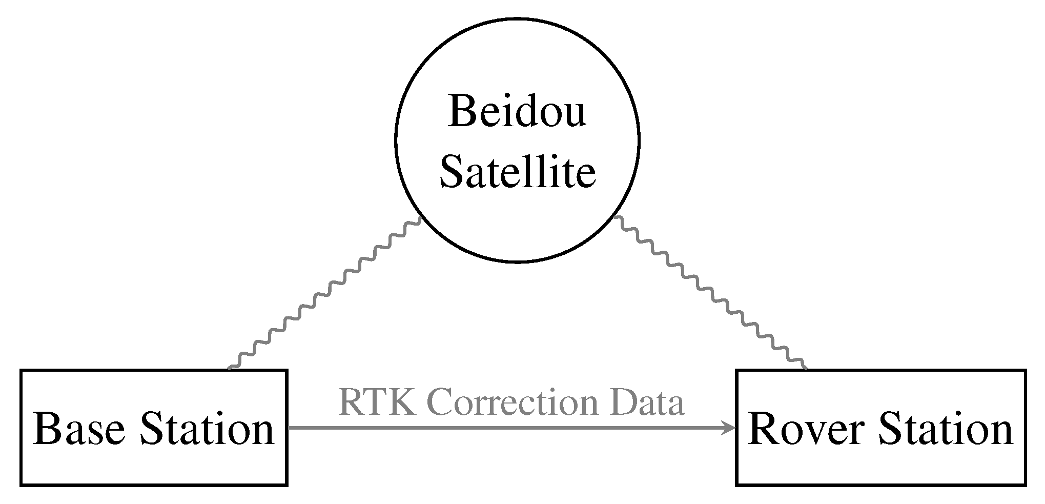
Figure 1 shows a schematic diagram of the application of RTK technology in the BBCN model.
RTK technology further utilizes real-time correction information provided by reference stations to achieve high-precision positioning via carrier-phase measurements.
2.1.2. Challenges of Beidou Positioning in Complex Environments
In complex industrial environments such as substations, the Beidou positioning system faces the following major challenges:
Electromagnetic Interference: The high-voltage equipment, transformers, and switch cabinets inside the substation generate strong electromagnetic radiation, which may interfere with the reception of Beidou signals, causing fluctuations in pseudorange measurement values and reducing positioning accuracy.
Signal Obstruction: Buildings, metal structures, and high-voltage line towers in the substation may block satellite signals, preventing the receiver from obtaining enough satellite signals simultaneously, thus affecting the reliability of positioning computation.
Multipath Effects: Satellite signals reflected on metal surfaces or walls cause multipath propagation, adding error terms to the pseudorange measurements, especially in environments with complex signal propagation paths.
Reference Station Layout and Data Transmission Delays: The distribution of reference stations around the substation and the potential delays or packet loss in data transmission between the reference stations and the robot’s receiver may affect the timeliness of RTK correction information.
2.1.3. Optimization Strategies for Beidou Positioning
To address the above challenges, this paper proposes the following optimization strategies, combining existing research and engineering practices, to improve the robustness and precision of the Beidou navigation positioning module in complex environments:
Signal Filtering and Error Compensation: To reduce the effects of electromagnetic interference and multipath effects, a Weighted Kalman Filter (WKF) is introduced for dynamic filtering and correction of pseudorange measurements. The state update formula for the WKF is as follows:
where
is the current state estimate;
is the predicted state at the previous time step;
is the Kalman gain;
is the current measurement (pseudorange);
H is the observation matrix;
is the state covariance matrix; and
R is the measurement noise covariance matrix. By assigning dynamic weights to pseudorange signals (e.g., higher-confidence satellite signals have higher weights), the WKF can maintain high positioning stability even when the signal is experiencing interference.
Multi-frequency Redundancy Design: The Beidou navigation system supports multi-frequency signals (such as B1, B2, B3), each with different interference resistance and signal penetration capabilities. By receiving signals from multiple frequencies and using least-squares optimization for pseudorange measurements, ionospheric and multipath errors can be effectively reduced:
where
is the pseudorange measurement value of the
i-th frequency band;
is the weight for each frequency band (determined by signal strength and confidence); and
is the optimized geometric distance. This strategy allows the system to still perform high-precision positioning by utilizing other frequency bands even when one band is experiencing interference.
Satellite Signal Selection and Geometry Optimization: To minimize the impact of signal obstruction, a satellite signal geometry optimization algorithm is used to select satellites with the best geometric distribution for positioning calculations. The satellite’s geometric precision factor (GDOP, Geometric Dilution of Precision) is calculated to assess signal quality:
where
G is the geometric precision factor, and
are the diagonal elements of the position and time covariance matrix. A lower
G value indicates a better satellite geometric distribution and higher positioning accuracy. In positioning computation, satellites with the smallest
G value are dynamically selected, improving computation quality in complex environments.
Data Redundancy and Fusion: To enhance the reliability of Beidou navigation data, multi-source data fusion based on the Unscented Kalman Filter (UKF) is introduced. This combines Beidou positioning data with Inertial Measurement Unit (IMU) data. The state transition and observation models of UKF are as follows:
where
is the next state;
is the current state;
is the control input;
is the current observation; and
and
are process and observation noises, respectively. The UKF compensates for the short-term, high-precision characteristics of IMU data while using Beidou data to correct IMU drift errors, thus maintaining high-precision positioning even in the case of severe signal interference or short-term signal loss.
2.1.4. Function Integration of Beidou Navigation Module
In the BBCN model, the Beidou navigation positioning module is responsible for providing the robot’s global position and state information, including the following:
Real-time calculation of the robot’s current global position coordinates and attitude.
Providing initial position references for the binocular vision module to assist in local path planning.
Collaborating with visual and IMU data in the data fusion module to enhance the overall system’s robustness and precision.
By optimizing filtering, redundancy design, and multi-source data fusion, the Beidou navigation positioning module proposed in this paper effectively improves positioning accuracy and robustness in the complex environment of substations, providing a stable global reference for binocular vision perception and path planning.
2.2. Binocular Vision Recognition and Perception Module
The binocular vision recognition and perception module is a key component of the Beidou–Binocular Cooperative Navigation Model (BBCN), responsible for providing the robot with the capability for real-time perception of the local environment. Compared to the global positioning information provided by the Beidou navigation positioning module, the binocular vision system mainly focuses on identifying obstacles and dynamic changes in the robot’s surrounding environment, while utilizing depth estimation algorithms to provide accurate three-dimensional spatial information. The binocular vision recognition and perception module closely collaborates with the Beidou navigation module to compensate for the limitations of the Beidou system in cases of signal interference or blockage. When Beidou signals fluctuate, the binocular vision system can generate a local environment map using methods like visual SLAM, providing the robot with short-term alternative positioning and path planning capabilities. Under normal conditions, the fusion of binocular vision recognition and Beidou navigation can further enhance the accuracy and robustness of path planning.
2.2.1. Principle of Binocular Vision
The binocular vision system consists of a pair of synchronized cameras. By capturing left and right images of the same scene, the system calculates depth information for the three-dimensional scene based on the disparity principle. Binocular vision generates dense depth maps that provide three-dimensional spatial information for path planning and obstacle detection. Additionally, by combining the binocular vision system with artificial intelligence algorithms (such as YOLO, DeepLab, etc.), objects in the scene can be detected and segmented, enabling the recognition of static and dynamic obstacles.
2.2.2. Main Functional Modules of Binocular Vision
Disparity Calculation and Depth Estimation: One of the core functions of binocular vision is depth estimation based on disparity. After calculating the disparity for each pixel in the left and right images captured by the cameras, the system converts this into depth values. The flowchart of disparity calculation and depth estimation is shown in
Figure 2.
Assuming the intrinsic and extrinsic parameters of the left and right cameras are
and
, respectively, for a point
in the scene, the pixel coordinates
and
in the left and right images are
where
is the rotation and translation matrix of the left camera relative to the right camera, and
I is the identity matrix, representing the coordinate system of the right camera itself. The relationship between disparity
d and depth
Z is
where
f is the camera focal length,
b is the baseline length of the binocular system, and
d is the disparity. Using depth estimation, the system can generate a dense depth map to describe the three-dimensional information of the entire scene.
Object Detection and Semantic Segmentation: This study used the deep learning-based object detection algorithm YOLO and the semantic segmentation algorithm DeepLab to detect and segment key targets and obstacles in the scene. YOLO is a regression-based object detection algorithm that transforms the object detection problem into a regression task for location and category, enabling target detection with extremely high speed and accuracy. Compared to other object detection methods (such as Faster R-CNN), YOLO features single-stage detection, directly generating predictions for object classes and locations from the input image, avoiding the complex process of generating candidate boxes. A schematic of the YOLO algorithm is shown in
Figure 3.
YOLO divides the input image into an grid, with each grid responsible for detecting objects that fall within its range. The model outputs the following information:
The coordinates of each grid cell’s bounding box , where is the relative position of the bounding box center, and are the width and height of the bounding box;
The confidence C of the bounding box, representing whether the box contains an object and the accuracy of the prediction;
The probability of the object class, used for identifying the object’s class.
The output tensor size of the model is
where
B is the number of bounding boxes predicted per grid, and
C is the number of object classes. The YOLO loss function consists of three parts: bounding box location loss, confidence loss, and class loss. In the BBCN model, YOLO is primarily used to detect key obstacles in the scene (such as transformers, switch cabinets, etc.). The detected bounding box positions and class probabilities are passed as inputs to the semantic segmentation module and the local path planning module for further obstacle segmentation and avoidance strategy formulation.
DeepLab is a powerful semantic segmentation algorithm, capable of partitioning the input image into multiple semantic regions, that is widely used in autonomous driving, robot navigation, and other scenarios. In the BBCN model, DeepLab is used to perform pixel-level obstacle segmentation on the images captured by binocular vision, thereby generating more accurate obstacle information. The core components of the DeepLab algorithm are as follows:
Dilated Convolution: By inserting holes in the convolution kernel, dilated convolution expands the receptive field while maintaining computational efficiency, capturing multi-scale contextual information. The output of dilated convolution can be expressed as follows:
where
r is the dilation rate,
K is the kernel size,
x is the output feature, and
w is the convolution kernel weights.
Atrous Spatial Pyramid Pooling (ASPP): ASPP extracts multi-scale features by using convolution kernels with different dilation rates in parallel, combining local information with global context. The output of ASPP is the fused result of multi-scale features.
Conditional Random Field (CRF) Post-processing: CRF post-processing is used to introduce contextual information into the prediction results and optimize the segmentation boundaries through a fully connected CRF, refining the results.
DeepLab uses the cross-entropy loss function to optimize the classification of each pixel:
where
N is the total number of pixels in the image,
C is the number of classes, and
and
are the true class and predicted probability of pixel
i, respectively. In the BBCN model, DeepLab is used to perform pixel-level semantic segmentation on the bounding box regions output by the object detection module (YOLO). For example, after YOLO detects a transformer, DeepLab further segments its pixel region, generating precise shape and boundary information for the obstacle. The segmentation results, combined with the depth map, are then input into the local path planning module for dynamic obstacle avoidance.
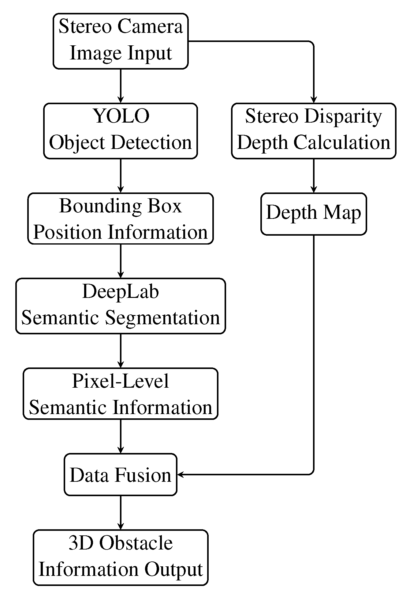
Figure 4 summarizes the collaboration between YOLO and DeepLab. Through the collaboration of YOLO and DeepLab, the BBCN model can precisely perceive the environment and provide support for dynamic obstacle avoidance and path planning.
Dynamic Object Detection and Tracking: The binocular vision system can also use optical flow methods or tracking algorithms to detect and track dynamic objects in real time. Supposing the pixel coordinates of the target point at time
t and
are
and
, respectively, the motion trajectory can be estimated using the optical flow method:
where
is the velocity change, and
and
are the image intensity gradients. Through dynamic object tracking, the system can promptly perceive environmental changes and update the path.
Figure 2.
Disparity calculation and depth estimation flowchart.
Figure 2.
Disparity calculation and depth estimation flowchart.
Figure 3.
Schematic diagram of YOLO algorithm.
Figure 3.
Schematic diagram of YOLO algorithm.
Figure 4.
Schematic diagram of YOLO and DeepLab collaboration.
Figure 4.
Schematic diagram of YOLO and DeepLab collaboration.
2.2.3. Local Path Planning of Binocular Vision
After generating depth information and identifying obstacles, the binocular vision module is responsible for providing obstacle avoidance capabilities through local path planning. Local path planning uses a grid map to represent the environment and employs the A* algorithm to compute the obstacle-free path:
Environment Modeling: A grid map is generated from the depth map, marking obstacle areas as impassable cells.
Path Search: Using the A* algorithm, the path from the robot’s current position to the target position is searched for the minimum-cost path.
Path Optimization: The local path is optimized in combination with the global path provided by Beidou, ensuring smoothness and reachability.
The core function of the binocular vision recognition and perception module in the BBCN model is to provide high-precision environmental perception and dynamic obstacle avoidance capabilities. Through close collaboration with the Beidou navigation module, this module not only compensates when Beidou signals are interfered with, but also dynamically adjusts paths during robot navigation to ensure efficient operation in complex environments.
2.3. Intelligent Collaborative Fusion and Path Planning Module
The Beidou and binocular vision modules in the BBCN model collaborate and fuse with each other. First, when Beidou signals are lost, the binocular vision system generates a local map using visual SLAM and performs short-term position estimation using odometry. Second, the binocular vision system provides real-time obstacle information to Beidou, enabling dynamic path adjustment when combined with global path planning. Finally, through the Unscented Kalman Filter (UKF), data from Beidou and binocular vision are fused to achieve global state estimation for the robot.
The intelligent collaborative fusion and path planning module is a core component of the Beidou–Binocular Cooperative Navigation (BBCN) model. The main task of this module is to fuse the global position information from the Beidou navigation positioning module with the local environmental information from the binocular vision recognition module, and to implement data fusion and dynamic path planning through intelligent algorithms. In complex environments such as substations, this module can effectively coordinate multi-source information, overcome the limitations of a single data source, adjust the robot’s path in real-time, avoid obstacles, and ensure the efficiency and safety of navigation. This module consists of three core parts: multi-sensor data fusion, global–local path planning coordination, and dynamic obstacle avoidance and optimization control. This section will detail the theoretical foundations and algorithm implementations.
2.3.1. Multi-Sensor Data Fusion
The Beidou navigation positioning module provides global position information, but is affected by signal interference and blockage. The binocular vision recognition module provides local environmental perception data with high accuracy, but cannot provide global position references. The intelligent collaborative fusion module uses the Unscented Kalman Filter (UKF) to fuse Beidou navigation data with binocular vision data, thereby generating a unified robot state estimate.
The choice of the Unscented Kalman Filter (UKF) is critical for the BBCN model, and this choice was made after careful consideration of alternatives such as the Extended Kalman Filter (EKF) and the Particle Filter (PF). The robot’s kinematic model and the sensor measurement functions are inherently non-linear. The EKF addresses non-linearity by performing a first-order Taylor series linearization, which can lead to significant estimation errors and even divergence when non-linearities are pronounced. The PF, while highly effective for non-Gaussian and non-linear systems, is computationally intensive as it requires a large number of particles to accurately approximate the posterior distribution, posing a challenge for real-time implementation on embedded hardware. The UKF, in contrast, uses the unscented transform to deterministically select a set of “sigma points” that capture the true mean and covariance of the state distribution up to the second order. This approach avoids the need for Jacobian matrix calculations and provides higher accuracy than the EKF for non-linear systems, while remaining significantly more computationally efficient than the PF. Therefore, the UKF represents the optimal trade-off between accuracy, robustness, and computational feasibility for our real-time multi-sensor fusion task.
The system’s state vector
includes the robot’s position, velocity, attitude, and errors from both the Beidou and vision sensors:
where
are the robot’s position information;
are the velocity components;
is the angular velocity;
is the Beidou positioning error; and
is the vision error.
Assuming the robot’s state
at time
is updated through a motion model, the state transition equation is as follows:
where
is the state transition function,
is the control input (such as speed and direction), and
is the process noise.
The observation model associates the measurements from the Beidou navigation module and the binocular vision module with the state vector:
where
includes the positions measured by Beidou
and by vision
;
is the observation function; and
is the observation noise.
The UKF models the state and observation uncertainties using unscented transforms without requiring linearization of the state equations, making it suitable for non-linear systems. The application of the UKF in the BBCN model is shown in
Figure 5.
By decomposing the state covariance matrix
,
sigma points are generated:
Each sigma point is substituted into the state transition equation, and the predicted observations are obtained through the observation model. By combining the actual observations
, the state is updated using the Kalman gain:
Through UKF fusion, Beidou navigation and binocular vision data are unified in the same coordinate system, providing accurate state estimates for path planning.
2.3.2. Global–Local Path Planning Coordination
Path planning is one of the core tasks of the navigation system, with the goal of finding the optimal path from the robot’s current position to the target position. The BBCN model combines the global path planning capabilities of Beidou with the local obstacle avoidance capabilities of binocular vision to propose a collaborative path planning method.
Global Path Planning: Global path planning is based on the global position information from the Beidou navigation module, and the A* algorithm is used to generate an initial path from the starting point to the target point. The path cost function is
where
is the path cost from the starting point to the current node
n; and
is the heuristic cost from the current node to the target node, typically using Euclidean distance.
Local Path Planning: Local path planning is based on the depth map and obstacle recognition results from binocular vision, generating real-time obstacle avoidance paths. The local path represents the environment using a grid map, where cells occupied by obstacles are marked as impassable; the A* algorithm is used to calculate the local path from the robot to the target point.
The cost function for the local path includes a dynamic obstacle avoidance weight:
where
represents the obstacle risk at node
n, and
is the obstacle weight coefficient.
Global–Local Collaborative Optimization: The global and local paths are combined in the coordination module, and the final path is obtained through a weighted optimization formula:
where
and
are the weight coefficients for the global and local paths.
2.3.3. Dynamic Obstacle Avoidance and Optimization Control
In dynamic environments, robots must avoid dynamic obstacles in real time and adjust their paths. This paper introduces the Riemannian Motion Policies (RMP) framework for dynamic obstacle avoidance and path optimization.
RMP describes the robot’s dynamic path adjustment through task acceleration fields, with the optimization goal as follows:
where
is the acceleration field for task
i, and
is the weight matrix. RMP decomposes path planning into multiple tasks, including guiding the robot towards the target point, generating avoidance acceleration fields near obstacles, and optimizing path smoothness via curvature.
The intelligent collaborative fusion and path planning module provides efficient path planning and obstacle avoidance capabilities for robots in complex environments through data fusion, global–local coordination, and dynamic optimization. The integration of this module ensures seamless connection between the Beidou navigation module and the binocular vision module, ensuring stable operation and flexibility in response to dynamic changes in substation environments.
2.4. Model Framework and Implementation
In the design of the Beidou–Binocular Cooperative Navigation Model (BBCN), each submodule (Beidou navigation positioning module, binocular vision recognition and perception module, intelligent collaborative fusion and path planning module) needs to be integrated through a unified framework to achieve seamless fusion of multi-sensor data, real-time path planning, and dynamic obstacle avoidance. This section will describe in detail the system framework design of the BBCN model, the data flow, and the implementation process.
2.4.1. Model Framework Design
The system framework of the BBCN model consists of three main layers: a sensor data input layer, a data processing and fusion layer, and a path planning and control layer. The tasks undertaken by each layer in the system are as follows:
Sensor Data Input Layer: This includes the Beidou navigation module and the binocular vision module. It is responsible for collecting global positioning data from the Beidou receiver and real-time images, depth maps, and environmental information captured by the binocular cameras.
Data Processing and Fusion Layer: The Beidou and binocular vision data are fused using the Unscented Kalman Filter (UKF) to generate a unified state estimate. Based on the fused data, the robot’s global position and local environmental information are updated.
Path Planning and Control Layer: At the global level, a global path is generated based on the target position provided by Beidou navigation. At the local level, the path is dynamically adjusted using obstacle information from vision recognition, and dynamic obstacle avoidance and path optimization are performed through Riemannian Motion Policies (RMP). The output includes low-level robot control commands, such as linear velocity and angular velocity.
2.4.2. Data Flow
The data flow of the BBCN model is divided into three stages: input, processing, and output. The specific steps are as follows:
Input Stage: The Beidou navigation module receives signals from the Beidou satellites and calculates the current position and attitude through differential positioning (RTK). It outputs global positioning information and Beidou state estimation errors. The binocular vision module’s left and right cameras capture synchronized images, calculate disparities, and generate depth maps. Object detection and semantic segmentation algorithms are applied to output the positions, categories, and local environmental maps of obstacles.
Processing Stage: The UKF fuses the global positioning data from Beidou with the local environmental data from vision, generating a unified robot state estimate. The depth map output by the binocular vision and the object detection results are converted into a 2D grid map, marking obstacles and free space. Based on the fused data, the path is planned by combining global path and local obstacle information, generating the dynamically adjusted optimal path.
Output Stage: The robot’s motion control commands are output, including linear velocity and angular velocity. If Beidou signals are lost, the system switches to visual odometry and local path planning mode.
2.4.3. System Implementation Process
The specific implementation process of the BBCN model is shown in
Figure 6.
Through the fusion processing of multi-sensor data, the collaborative optimization of global and local path planning, and real-time dynamic obstacle avoidance control, the BBCN model can provide efficient navigation capabilities in complex environments. The next chapter will cover the simulations and physical experiments conducted to validate the model and evaluate its actual performance.
3. Experiments
To validate the performance of the Beidou–Binocular Cooperative Navigation Model (BBCN), experiments were conducted to evaluate its global positioning accuracy, dynamic obstacle avoidance capability, and path planning efficiency in complex environments. The experiments utilized a robotic platform to test its performance in a substation’s complex environment. The experimental scenarios included fixed obstacles, dynamic obstacles, and electromagnetic interference areas. The evaluation focused on the BBCN model’s own performance while also comparing it with other models to highlight its advantages in multi-sensor fusion and adaptability to complex environments.
3.1. Experimental Setup
The experiments were conducted at a 10 × 10 m outdoor testing facility in Harbin, China (45.75° N, 126.63° E), which was designed to simulate the typical characteristics of a substation and included various obstacles, dynamic elements, and electromagnetic interference sources.
3.1.1. Experimental Scenarios
The experimental scenarios included the following elements:
Fixed Obstacles: Including metal walls, columnar equipment, and narrow passages, simulating the common equipment distribution in substations. These were primarily used to test the accuracy of robot path planning.
Dynamic Obstacles: Including randomly moving vehicles and people, simulating dynamic interference in industrial environments, and testing the model’s dynamic obstacle avoidance ability.
Electromagnetic Interference Areas: Using virtual signal sources to simulate the electromagnetic interference caused by high-voltage equipment, leading to Beidou signal instability. This tested the model’s emergency handling capabilities under weak- or lost-signal conditions.
Target Point Layout: Multiple target points were set in this scenario, covering areas of varying complexity to validate the model’s robustness in different navigation tasks.
All experiments were conducted under controlled and consistent environmental conditions to ensure comparability. The ambient lighting was maintained at approximately 500 lux. The electromagnetic interference was simulated using a signal generator, with “Moderate” and “High” levels corresponding to predefined, repeatable power spectral densities applied to the Beidou signal receiver.
3.1.2. Experimental Scenario Visualization and Equipment
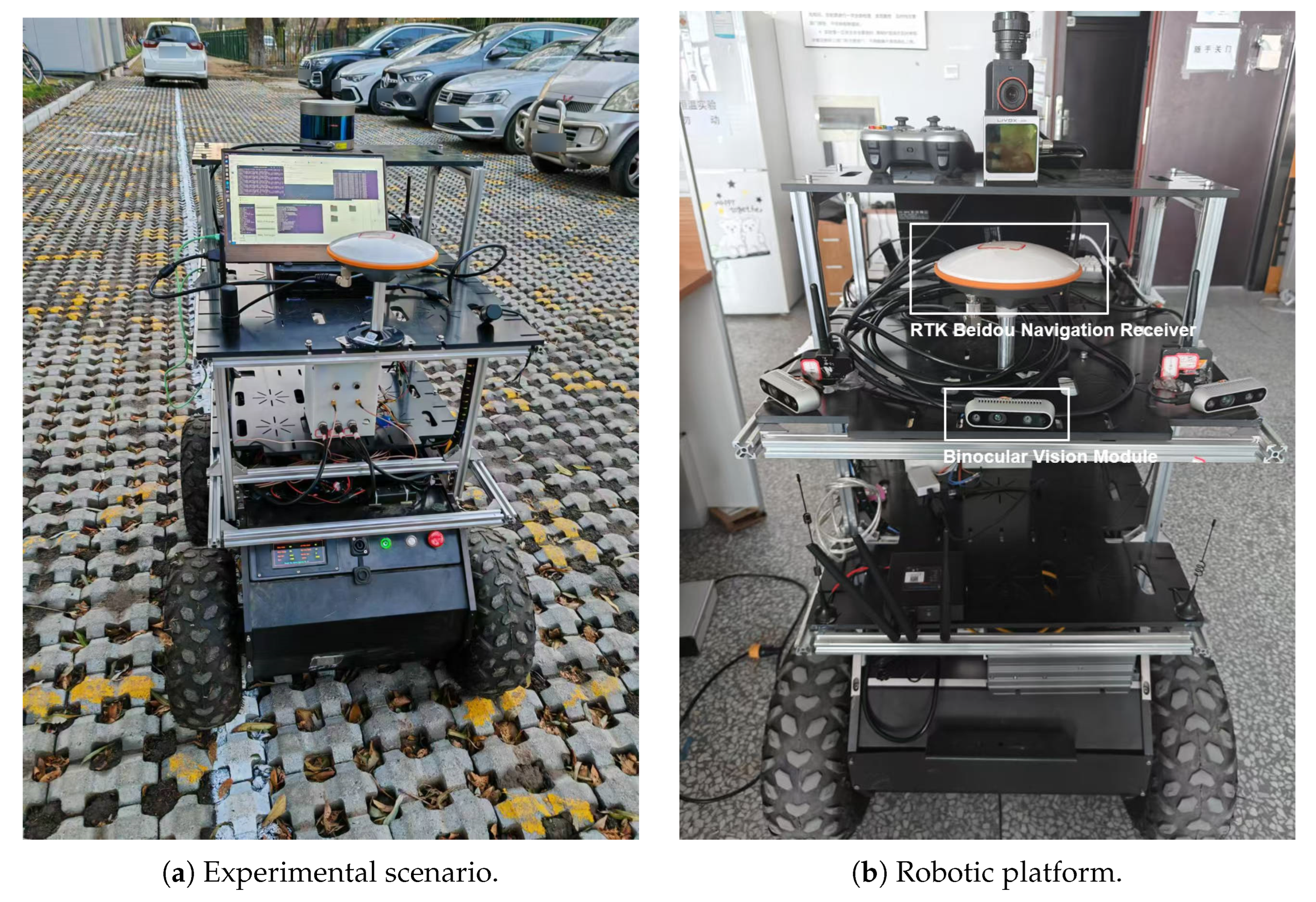
To provide a more intuitive representation of the experimental environment,
Figure 7a shows the actual scenario for testing the BBCN model. As illustrated, the experimental platform was deployed in a simulated substation environment featuring complex ground structures and surrounding obstacles. The test site was paved with permeable bricks to simulate the complex terrain inside substations, facilitating the evaluation of the navigation model’s adaptability under various surface conditions. The surrounding area also included static obstacles (such as parked vehicles) and designated zones for dynamic obstacle movement, providing a realistic environment for testing the system’s obstacle avoidance capabilities.
The experiment utilized a robotic platform equipped with sensor modules and a data processing system. The sensor modules included a RTK Beidou navigation receiver; the binocular vision module was equipped with an Intel RealSense D455 camera, providing left and right images as well as depth maps for local environment modeling and dynamic obstacle avoidance. An IMU sensor (MPU-9250; InvenSense Inc., San Jose, CA, USA) was used to provide attitude estimation data. It is important to note that the magnetometer integrated within the IMU was deliberately disabled. Its data were excluded from the fusion algorithm because substation environments contain strong, fluctuating magnetic fields from high-voltage equipment, which introduce significant and unpredictable errors into the heading estimation, making magnetometer data unreliable for this specific application. The experimental equipment is shown in
Figure 7b. The performance of the robotic platform in real-world environments directly impacts the efficiency of data acquisition and the control system. The experimental control system was based on the ROS 2 framework, responsible for real-time collection and processing of sensor data, as well as path planning and motion control.
3.1.3. Evaluation Metrics and Comparison Models
The following quantitative metrics were used to evaluate the performance of the BBCN model:
Global Positioning Error (GPE): The average Euclidean distance between the robot’s actual position and the target position.
Path Efficiency (PEF): The ratio of the actual path length to the ideal optimal path length, reflecting the optimality of the path planning.
Obstacle Avoidance Success Rate (OASR): The percentage of successful obstacle avoidance in dynamic environments.
System Latency (SL): The time taken for sensor data processing and control command generation, reflecting the real-time performance of the system.
The following common models were compared:
Single Beidou Navigation Model (GNSS): Only relies on Beidou navigation for global path planning, with no local perception capability.
Vision-based Local Navigation Model (Vision-SLAM): Uses visual SLAM for positioning and path planning.
Beidou and Vision Fusion Model (GNSS-Vision): Uses the Extended Kalman Filter (EKF) to fuse Beidou and vision data for navigation and obstacle avoidance.
3.2. Experimental Steps
Step 1: Scene Initialization. In the experimental environment, obstacles and target points representing the substation layout were arranged. The setup included defining the positions of fixed obstacles, the movement trajectories of dynamic obstacles, and the coverage area of electromagnetic interference zones. The distance between the robot’s starting point and target points ranged from 6 to 12 m, ensuring the evaluation of both short-range and long-range navigation tasks.
Step 2: Sensor Data Collection. The robot sensor modules were activated to collect the following data:
Beidou navigation data: Global positioning data were generated through the virtual RTK module with a frequency of 1 Hz.
Binocular vision data: Left and right images and depth maps were generated with a frequency of 30 Hz.
IMU data: Attitude information was output with a frequency of 100 Hz.
Step 3: Navigation Task Execution. The Beidou–Binocular Cooperative Navigation Model was activated, fusing multi-sensor data to perform path planning and navigation tasks. The GNSS, Vision-SLAM, and GNSS-Vision models were run in the same scenario to complete navigation tasks.
Step 4: Data Recording and Processing. For each navigation task and model configuration, the experiment was repeated 10 times. The global positioning error, actual path length, dynamic obstacle avoidance outcomes, and system processing delay were recorded for each run. The final reported metrics are the average of these 10 trials, and statistical data, including standard deviation, were generated for analysis.
3.3. Experimental Results and Analysis
The experimental results were analyzed and measured in terms of positioning accuracy, path planning efficiency, obstacle avoidance ability, and real-time system performance.
3.3.1. Global Positioning Error (GPE)
The experiment varied the scene complexity (obstacle count) and electromagnetic interference strength, recording the positioning error of the BBCN model and comparing it with that of other models. The results are shown in
Table 1.
The GPE of the BBCN model remains under 5 cm under no-interference conditions. Even in high-electromagnetic-interference scenarios, thanks to the compensation from the binocular vision module and IMU, the positioning error only increases to 6.2 cm, demonstrating excellent resistance to interference.
Table 2 shows a comparison of the GPE under high interference for the BBCN model and other models.
Compared to the GNSS model, whose GPE significantly increases with interference, reaching 40.2 cm, the BBCN model reduces the error by 84.5%. The BBCN model also reduces positioning errors compared to the Vision-SLAM and GNSS-Vision models, further demonstrating the effectiveness of multi-sensor fusion in complex environments.
3.3.2. Path Planning Efficiency (PEF)
By setting target points with different distance ranges, the path length data for the BBCN model were recorded, and the PEF was calculated. The path planning efficiency of the BBCN model is shown in
Table 3.
The BBCN model maintains a high path planning efficiency close to 1 across different distances and complex environments, indicating that the model generates near-optimal paths. Even in environments with dense obstacles, the efficiency remains below 1.05, demonstrating high adaptability.
3.3.3. Dynamic Obstacle Avoidance Success Rate (OASR)
In the simulation environment, dynamic obstacles (randomly moving vehicles and people) were set, and the obstacle avoidance performance of the BBCN model and other models was tested. The results are shown in
Table 4.
The BBCN model achieved a 95% success rate in dynamic obstacle avoidance, significantly outperforming the other models. The GNSS model, which relies entirely on global path planning and lacks local perception, achieved only a 40% success rate in dynamic obstacle scenarios. The Vision-SLAM model, while capable of local perception, was unstable in handling fast-moving obstacles, achieving 80% success. The GNSS-Vision model, which fuses Beidou and vision data using the EKF, showed an improvement, but still had a lower success rate than the BBCN model. This demonstrates that the BBCN model, with its dynamic path optimization and efficient collaboration mechanism, can more reliably handle dynamic obstacle scenarios.
3.3.4. System Latency (SL)
During the experiment, the sensor data collection frequency was adjusted and the average system latency for the BBCN model was recorded, as shown in
Table 5.
At a 30 Hz data collection frequency, the latency of the BBCN model is controlled within 80 ms, meeting real-time requirements. Latency slightly decreases with an increase in data frequency, as high-frequency collection reduces the waiting time for data buffering. Compared to other models, the GNSS model has the lowest latency, but lacks local perception and data fusion capabilities. The Vision-SLAM model has the highest latency, mainly due to the higher computational demands of visual SLAM. The BBCN model achieves real-time performance close to that of the GNSS-Vision model, demonstrating good stability and real-time capability.
3.3.5. Computational Cost Analysis
To evaluate the real-time feasibility of the BBCN model, we analyzed the computational cost of its main components using the NVIDIA Jetson AGX Xavier platform. The average processing time per cycle for each key module is presented in
Table 6. The visual perception tasks, particularly semantic segmentation with DeepLab, represent the most computationally intensive part of the pipeline. However, by leveraging GPU acceleration, the total processing time for the entire navigation loop is maintained at approximately 80 ms, which is well within the real-time requirements for robotic navigation at a control frequency of over 10 Hz.
4. Conclusions
This paper proposes an intelligent collaborative navigation model (BBCN) based on Beidou high-precision navigation and binocular vision recognition to address the specific needs of robot navigation in the complex environment of substations. The model’s effectiveness was verified through simulation experiments. The research focuses on the system’s global positioning capabilities, local path planning capabilities, and dynamic obstacle avoidance performance, solving the issues of Beidou signal interference and blockage in complex industrial environments, and providing a multi-sensor fusion navigation solution.
First, this paper deeply analyzed the complex characteristics of substation environments, including the effects of electromagnetic interference, signal blockage, and dynamic obstacles on navigation performance. A collaborative solution was proposed where Beidou navigation provides global positioning references, combined with binocular vision for local environmental perception. By using the Unscented Kalman Filter (UKF) to fuse Beidou positioning data with vision data, the BBCN model can maintain high positioning accuracy in complex environments. Additionally, a collaborative path planning method was designed, combining global and local paths, and dynamic path adjustment and obstacle avoidance strategies were employed to ensure the robot’s navigation safety and efficiency in dynamic environments.
Experimental results show that the BBCN model exhibits significant performance advantages in the simulation environment. In terms of global positioning, the positioning error of the BBCN model remained within 5 cm under no-interference conditions. Even under high electromagnetic interference, the error increased only to 6.2 cm, significantly outperforming the single Beidou navigation model and other comparison models. In terms of path planning efficiency, the actual path generated by the BBCN model closely matched the ideal path, with a nearly optimal efficiency factor (close to 1), demonstrating high adaptability in obstacle-dense environments. In dynamic obstacle avoidance, the BBCN model achieved a 95% success rate, reliably handling interference from dynamic obstacles, far exceeding traditional GNSS models and single-vision navigation models. Additionally, the system latency of the BBCN model was controlled within 80 ms, meeting the real-time requirements of industrial scenarios.
The innovation of the BBCN model lies in its provision of a targeted solution to the unique challenges of substation environments, representing a significant advancement in the practical application of autonomous robotic systems in the power industry. By successfully addressing the electromagnetic interference and signal blockage issues that have previously limited automation in substations, this research opens up new possibilities for comprehensive intelligent inspection and maintenance operations. The practical applications of this technology extend beyond basic navigation to enable fully autonomous equipment inspection, real-time fault detection, preventive maintenance, and emergency response in high-voltage environments—tasks that traditionally expose human workers to significant safety risks. Economic benefits include reduced labor costs (with potential savings of 40–60% on routine inspection tasks), minimized power outages through more frequent and thorough inspections, extended equipment lifespan through early fault detection, and improved operational safety. As power infrastructure continues to expand and age globally, the BBCN model provides a timely solution for power utilities seeking to modernize their maintenance strategies while addressing workforce challenges. The methodology developed in this research also establishes a foundation for future intelligent operation systems in other complex industrial environments with similar navigation challenges.
However, the authors acknowledge certain limitations that present avenues for future research. The current study was conducted under controlled lighting conditions, and the robustness of the binocular vision system under adverse environmental conditions—such as low light, high glare, fog, or heavy rain—has not been fully evaluated. These conditions can degrade the quality of visual data, potentially impacting the accuracy of depth estimation and object detection. Future work should focus on enhancing the system’s resilience to such challenges. Potential strategies include the integration of pre-processing algorithms for image enhancement and the development of an adaptive fusion mechanism. In such a mechanism, the measurement noise covariance (R) within the UKF could be dynamically adjusted based on real-time image quality metrics, thereby down-weighting the contribution of the visual system when its reliability is compromised. Furthermore, incorporating additional sensor modalities, such as thermal imaging or LiDAR, could provide complementary data to ensure robust navigation across all environmental conditions.


