1. Introduction
Earthwork operations are critical components of most construction projects and involve significant volumetric modifications of the terrain. These operations are inherently cyclic, as multiple pieces of equipment, such as excavators and dump trucks, are utilized to excavate, transport, and fill earthwork materials. Earthwork construction has a dynamic nature and unique characteristics, including an unstructured work environment such as irregular terrain and inhomogeneous earthwork material properties, the presence of utilities or unstable soil, unexpected rock layers, large-scale operations involving volumetric designs and significant material quantities, difficult scene perception, particularly in underground construction, and limited visibility of machine operators [
1]. During construction, two significant challenges arise, as follows: (1) simulating the interaction between an unstructured environment and equipment during earthwork activities, and (2) the difficulty in integrating all the information and dynamically updating the model to reflect the as-built status. These challenges often create safety issues, impacting the productivity and quality of earthwork construction. Hence, a system is needed that can support the integration of all information in an integrated environment, represent earthwork characteristics realistically, and support real-time simulation and dynamic monitoring for efficient earthwork management.
The digital twin connects the physical and virtual assets/processes, enabling seamless integration and control. It uses sensing technologies to capture as-built information and utilizes advanced modeling, visualization, and simulation techniques to accurately represent, analyze, and optimize the system during the operation [
2]. At its core, the digital twin serves as a manipulable virtual replica, allowing users to gain insights into the behavior and performance of the physical system [
3]. To be effective, the virtual twin must be built with a high degree of fidelity, incorporating the spatial, material, and temporal dynamics of its physical counterpart [
4]. Additionally, the virtual twin and physical twin are linked in a bidirectional way, meaning that the changes in the physical environment, such as excavation volume and materials, must be reflected in the virtual twin. Equally, insights from the virtual twin should be used to guide the project stakeholders for accurate and timely decisions [
5]. Therefore, in the context of earthwork, a realistic and data-rich virtual twin is fundamental, as it could represent dynamic earthwork processes, including the representation of heterogeneous earthwork materials, interactions, and the volumetric changes that occur during the construction.
Several review articles provide definitions, challenges, opportunities, and current methods for data acquisition, data integration, data linkage between physical and digital components, twin representations, and advanced tools for improving systems and making decisions effectively [
4,
6,
7,
8,
9,
10,
11]. Most of the proposed definitions and frameworks share three fundamental components of a digital twin, as follows: the physical twin, the digital twin, and the connections [
12]. Tao et al. [
13] proposed a generalized framework of the following five components: digital components, virtual components, data, connection, and services. In recent years, digital twin applications have gained substantial attention in the construction industry, particularly for monitoring, simulation, and optimization of physical processes. For example, a digital twin framework for construction equipment monitoring, progress monitoring, and visualization was developed. It provides information about equipment tracking using Internet of Things (IoT) data and dashboard visualization [
14]. Drone-based photogrammetry and computer-aided design (CAD) data were integrated to track road base construction in a digital twin environment [
15]. A scan-to–building information modeling (BIM) approach was utilized for bridge construction monitoring, leveraging laser scanning data and BIM models to enhance progress monitoring [
16]. A framework was developed that uses vision data and IoT data to collect the progress and resource data for construction status assessment, visualization, and prediction [
6].
These studies underscore the growing relevance and versatility of digital twins in improving the efficiency, accuracy, and visualization of the construction stage. Despite these advancements, existing digital twin approaches in construction face several limitations, particularly when applied to earthwork construction. For example, previous studies relied on static BIM or CAD models for virtual twin development to represent the as-planned model while collecting data from physical objects [
17]. These models do not reflect earthwork properties, which are based on inhomogeneous geotechnical characteristics, and support volumetric changes that occur during excavation and filling [
18]. The modeling needed to develop a virtual twin for earthwork is fundamentally different. Structural components typically possess homogenous characteristics and can be represented as discrete, object-based elements within a BIM environment; however, earthwork elements such as terrain and soils are irregular and heterogeneous, characterized by uncertain properties that vary spatially and temporally [
18]. Additionally, unlike structural components that are installed or constructed according to the static as-planned designs, earthwork is inherently operational, involving dynamic changes to the terrain in a volumetric manner due to the filling and excavation activities [
19]. Capturing these dynamic characteristics of earthwork requires specialized geometric modeling that can represent its complexity in a spatially accurate and semantically rich manner, enabling the virtual twin to reflect realistic conditions and adapt to the evolving physical twin [
20].
Apart from this, recently proposed vision-based methods for digital twin creation provide excellent capabilities to capture dynamic changes in the construction environment; however, the earthwork digital twin requires additional information, such as material properties, for semantically specific simulations and progress monitoring [
21]. Moreover, they capture point-based information, such as point clouds, which are converted into surfaces and do not support volumetric reasoning, which is crucial for managing cut-and-fill operations [
22]. Most importantly, integration between geometric and semantic twin sources (such as design information, construction dataset monitored from the physical twin, and geotechnical parameters) is typically ad hoc [
23]. A holistic system that integrates the information in a unified platform with an update function, not only for the geometric information but also for the earthwork semantics, is needed and can contribute significantly.
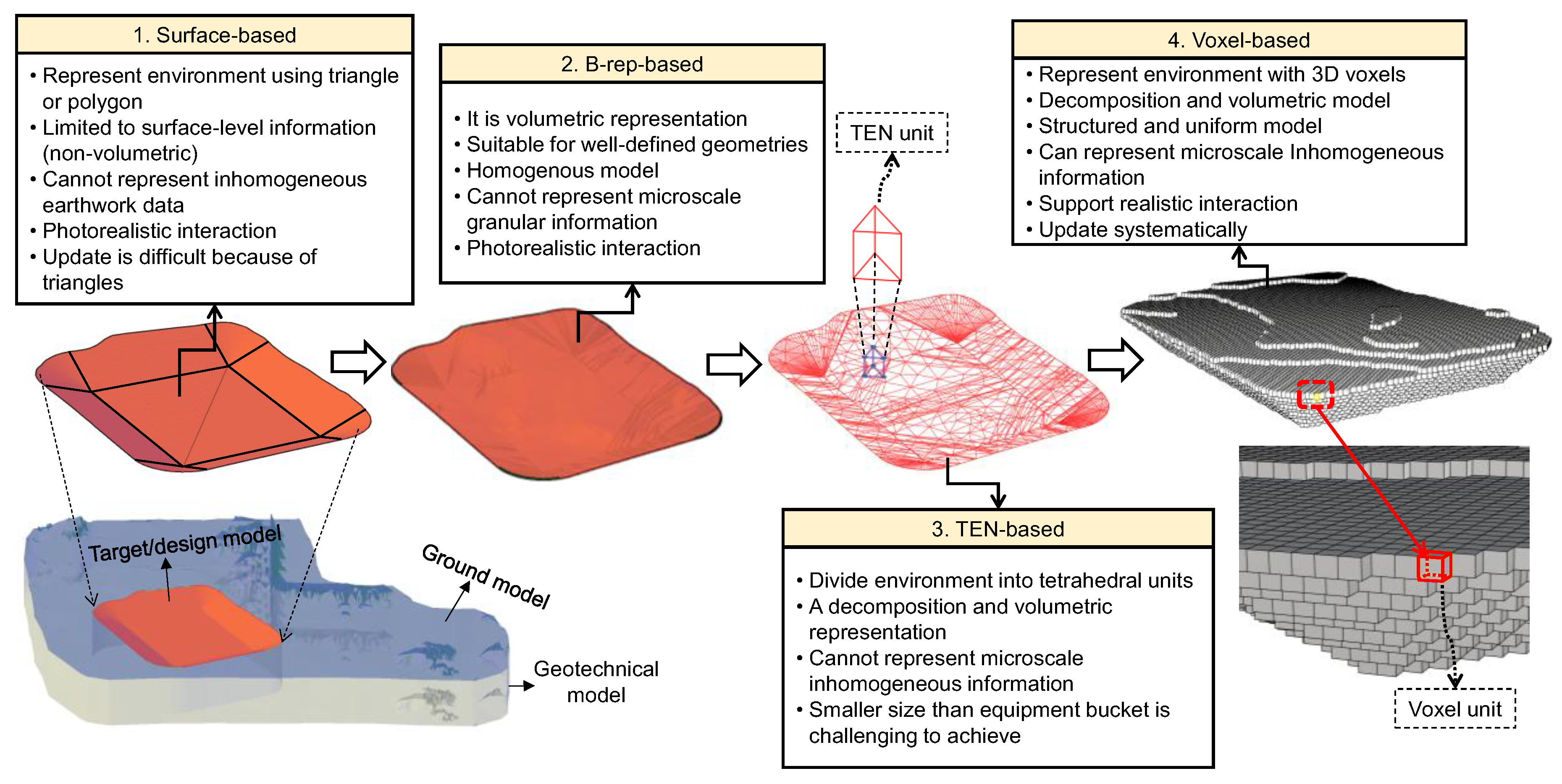
Voxel-based representation offers a robust solution to address the inherent challenges, making it highly suitable for the development of a realistic earthwork digital twin [
24]. The advantages of the voxels in this context are as follows: (1) voxels are a volumetric unit created by discretizing the as-planned or as-built model into three-dimensional (3D) cells/cubes, capturing the realistic representations of earthwork characteristics. (2) Voxels are scalable and their size can be refined, allowing for the detailed representation of uncertain earthwork properties [
25]. (3) Each voxel can integrate semantic information such as soil type, cohesion, strength, moisture content, unit cost, and excavation time, enabling detailed monitoring of earthwork conditions. This embedded semantic information not only supports material-specific simulation during model–equipment interaction but also allows for tracking which materials have been excavated or filled during construction. (4) Voxels can be systematically updated when new sensing data becomes available, supporting real-time tracking and productivity assessment at an operational level. Despite these advantages, the practical implementation of voxel-based models for earthwork digital twins, particularly their efficient creation, visualization, updating, and management in a constantly changing environment, remains a significant research challenge [
4,
26].
This article proposes a voxel-based digital twin framework for earthwork construction that addresses the critical gaps. The framework is designed to integrate the earthwork information (including terrain, geotechnical, design, and construction data) and uses voxels for the as-planned and as-built modeling, enabling volumetric representation and allowing for real-time simulation and progress tracking. The proposed framework has been validated through real-world case studies, demonstrating the system’s effectiveness in providing a high-fidelity, operationally insightful digital twin for earthwork. Moreover, the scope of this study is primarily focused on the virtual twin creation for earthwork, the development of graphical simulations that facilitate model–equipment interaction, and the monitoring of progress through the dynamic integration of construction data from the physical twin to the digital twin. The primary objective of the proposed study is to achieve a voxel-based digital twin framework that overcomes the limitations of the existing representation schemes. The particular objectives are as follows: (1) to integrate terrain, geotechnical, and construction data, with an update function, into a unified voxel-based environment; (2) to represent heterogeneous earthwork semantics through attribute-rich voxels; (3) to enable volumetric modeling of as-planned and as-built earthwork conditions; (4) to facilitate earthwork model–equipment interaction and progress monitoring with semantic tracking during construction. By achieving these particular goals, the proposed system bridges the gap between static modeling practices and dynamic earthwork management needs, contributing to improved automation, visualization, and decision-making in a complex construction environment.
3. Methodology
3.1. Proposed Voxel-Based Digital Twin Framework
The proposed voxel-based digital twin framework for earthwork construction is presented in
Figure 2. The proposed framework digitally replicates and manages earthwork construction through the following five components: physical parts, digital parts, data, connections, and services. At its core, the physical parts represent real-world entities on construction sites, including terrain, excavation and filling zones, geotechnical properties, and heavy equipment such as excavators and dump trucks. These physical parts are actively engaged in earthwork activities. For instance, the terrain changes volumetrically, which is captured through sensing technologies such as photogrammetry or laser scanning. Equipment operations at the construction site continuously generate data that reflects the evolution and serves as a data source for the updated digital twin.
The digital part of the framework involves the representation of each physical part in a 3D environment, such as through BIM models. The terrain, geotechnical, design, and construction data are modeled and embedded with semantic information. Additionally, this includes a simulation of the earthwork operation, where equipment and models interact based on the as-built data. The digital counterpart facilitates both real-time model updating and simulation, enabling stakeholders to analyze the current state, simulate future scenarios, and visualize previous activity sequences.
The data, connectivity, and service components of the framework contribute to developing the operational layer of the system. The data component integrates earthwork construction-related information such as geotechnical parameters, terrain information, equipment specification, design models, and as-built scans. The connection layer provides seamless communication between the physical and digital parts, ensuring volumetric updates and feedback. The service layer delivers application functions, including model–equipment interaction simulation, material tracking, and volumetric analysis. These components are linked together, creating a highly integrated and context-aware digital twin system tailored for earthwork construction.
3.2. Proposed Digital Twin Architecture
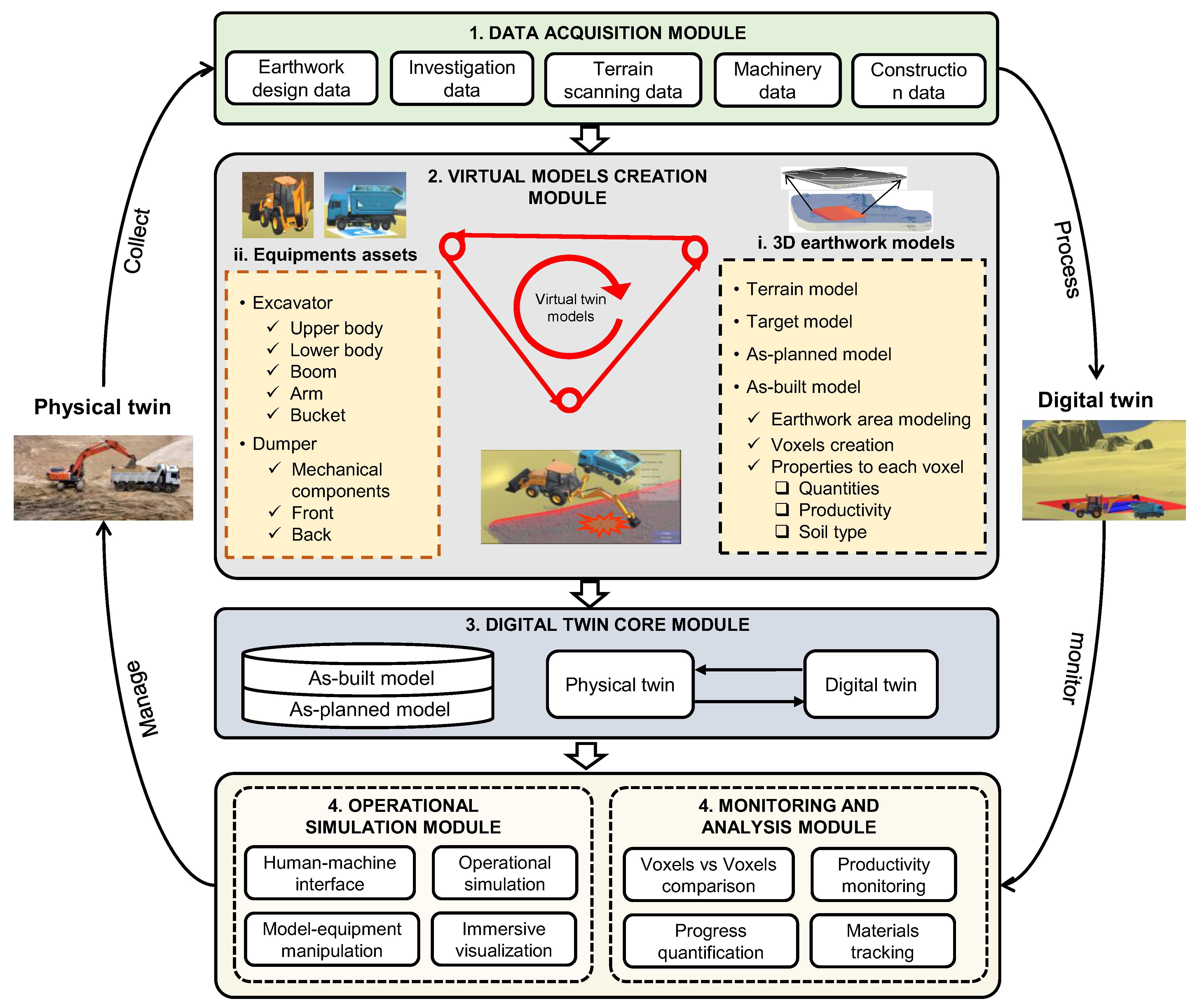
The proposed framework for earthwork construction is structured around five interconnected modules that cumulatively allow the creation, synchronization, visualization, simulation, and monitoring of the dynamic earthwork process (
Figure 3). The modules are as follows: (1) data acquisition, (2) virtual model creation, (3) digital twin core, (4) visualization and simulation, and (5) monitoring and analysis.
3.2.1. Data Acquisition Module
This module collects multi-source information, which forms the foundation of the digital twin. The data sources are broadly categorized into construction site data and equipment data. Construction site data consist of subsurface, surface, and design data, such as target models, cut/fill zones, and as-built construction data collected during operation. Subsurface data represent the underground material conditions and their characteristics, which can be collected through geotechnical investigations. Boreholes provide data on the earthwork material at different depths, along with other in situ and laboratory test results, to achieve geotechnical stratigraphy and properties such as material type, strength, cohesion, friction, and ground level.
Surface data, which represents the existing ground conditions, can be obtained from publicly available datasets such as the National Geographic Institute of Korea (NGII), the United States Geological Survey, OpenStreetMap, and GIS. However, these datasets are inaccurate because of scale changes and outdated formats. Advanced technologies, such as laser scanning and photogrammetry, can be used to capture surface data with millimeter-level accuracy. In addition to accuracy, it is important to obtain the current state of information for realistic simulations, which is lacking in the public datasets. In addition, earthwork design data, including BIM models, CAD data, and earthwork quantity reports, provide targets and cut-and-fill information.
Construction data is acquired regularly using cameras or laser scanners, ensuring that both static and dynamic field data are captured for downstream use. Another critical data source is the equipment used for model manipulation. Equipment data are obtained either by scanning onsite or from equipment specifications, such as equipment-specific dimensions, capacity, and mobility parameters that influence the simulation performance. In addition, kinematic and dynamic equipment data can be obtained from the onboard sensors and telemetry systems. Moreover, automated machine guidance (AMG) can provide significant information about the equipment at a construction site.
3.2.2. Virtual Model Creation Module
After collecting essential data on the construction site and equipment, the next step is to create virtual simulation models that have similar characteristics to the physical models. At this stage, it is assumed that the collected data are sufficiently accurate to be used for virtualization.
This module is responsible for the as-planned and as-built model generation. The as-planned model represents the design models that are scheduled to be excavated or filled. These models include the preprocessing of terrain and terrain modeling, subsurface modeling, design target modeling, and conversion of the design model into a voxel-based model. Additionally, they include the semantic assignment to each voxel, such as material type, strength, moisture content, excavation time, cost, and construction status (a detailed process of voxelization is discussed in
Section 3.3.3). This information is appended to each voxel with the aim of utilization in the downstream stages. For example, the material information attached to each voxel is used for material tracking. Moreover, the equipment is configured within the virtual environment that is used for model–equipment simulation. On the other hand, the as-built model is acquired through a sensing technique and continuously updated to reflect the as-built condition. The as-built is integrated with the as-planned to reflect the current state of information.
3.2.3. Digital Twin Core Module
At the center of the proposed framework, the digital twin core module links the physical and digital twins in an integrated environment. It serves as an integration layer that connects the as-planned and as-built models. This module ensures that the physical and digital twins are synchronized, provides the simulation and progress information according to the as-is condition, and evolves continuously with the construction.
3.2.4. Visualization and Simulation Module
This module provides a graphical simulation interface for interaction with the model and equipment in an interactive and immersive environment. It integrates the as-is condition information, including ground, target, and design or as-built voxels, along with the construction equipment, such as an excavator and dumper. The equipment is utilized to simulate a voxel-based earthwork environment according to its semantics, enhancing the situational awareness of construction site information, as well as facilitating scenario analysis and effective decision-making.
3.2.5. Monitoring and Analysis Module
The monitoring and analysis module uses the as-planned and as-built voxels to support the real-time tracking of progress. It enables monitoring the productivity of earthwork construction at the voxel level. The key characteristic of this module is that it not only tracks volumetric information but also material information. Additionally, it continuously provides earthwork quality information using a visualization model of the deviation between as-planned and as-built voxels. This module plays a significant role in facilitating project managers to make decisions based on data-driven analysis, ensuring that the project is completed according to the planned objectives.
These five connected modules are linked together to form a robust and intelligent digital twin tailored for earthwork construction. Integrating voxel-based modeling, game-engine–supported model–equipment simulation, semantic data modeling, and real-time sensing data forms an advanced platform for earthwork construction visualization, simulation, and monitoring.
3.3. Earthwork Virtual Model Construction
The purpose of virtual models in earthwork construction is to develop a virtual environment containing a digital representation of the physical entities and their characteristics. The realism, accuracy, and computation of the simulation are highly dependent on the model’s level of detail (LOD), which is directly correlated with its representation. For example, the as-planned model represents excavation materials to be removed, which requires a detailed representation with a higher LOD. Each earthwork model employs distinct geometric modeling to balance computational efficiency with fidelity to actual earthwork conditions.
3.3.1. Surface and Geotechnical Model
The original ground model digitally represents the terrain topography, slopes, design zones, and their properties. Several representations were reviewed to select the ground model type. The ground model provides a static environment for equipment mobility and is not directly manipulated by the equipment. Hence, a simplified and accurate TIN-based surface modeling approach was used to represent the ground conditions. TIN constructs a mesh model of irregular triangles from drone surveys or LIDAR scans to represent complex and large-scale geographical conditions (
Figure 4a).
The geotechnical model represents the variation in geological profiles, along with characteristics such as earthwork materials, bearing strength, and moisture content. Investigation reports and borehole data were used to generate a subsurface model. B-rep was used to represent the subsurface volumetric information by defining the geometries using the boundary surfaces. Before modeling, the borehole coordinates were transferred from the local to the standard Universal Transverse Mercator (UTM) to obtain georeferenced data. The borehole coordinates were then transferred using a transformation equation.
For a borehole point p = [x, y, z]
⊤ in the local coordinate system, its transformed position is
where R is a rotational matrix and t is a translational vector.
Assuming the boreholes are created vertically, their coordinates are determined through the following equation:
where
, and t
x, t
y, and t
z are translations in the x-, y-, and z-directions, respectively.
After determining the coordinate values for each borehole, they were integrated with the ground surface and modeled. First, boreholes were created from the point data at different depths obtained through a geotechnical investigation (
Figure 4b). Layers were created at each depth to obtain surface information for each material type (
Figure 4c,d). The top and bottom layers of each material were used to develop the volumetric B-rep model (
Figure 4e,f). A detailed method for creating the geotechnical model can be found in our previous article [
24].
3.3.2. Target Model
In earthwork operations, the equipment operates in a continuously changing environment because the materials are either removed or filled. The target model presents the grade line or final information to equipment operators or managers. As this model only provides a target to assist the operator, a TIN-based surface is used to represent the target model.
Figure 5a shows the target model design, considering the earthwork cut or excavation scenario.
3.3.3. Voxel-Based As-Planned/As-Built Model Development
The proposed method uses voxel-based representation for the design model and the as-built model. The design model represents the volume between the target model and the ground model. To voxelize a design model or an as-built model, the voxelization process is used. Voxelization converts the geometrical models into cubes, where each cube can be assigned different properties and semantics. The voxelization process of the earthwork model is explained in detail in our previous article [
25]. The method uses a three-step procedure, as follows: (1) solid extraction between the target and ground models, (2) conversion of the solid model into a mesh model, and (3) voxel generation inside the mesh. The process is depicted for an excavation example in
Figure 5.
The solid was extracted in the first step using the ground and target surfaces. The triangles of the TIN surfaces were utilized to extract the solid that represents the homogenous volumetric details of the cut or fill, providing clear boundaries with topological information. The extracted solids were converted into meshes. The conversion of the design model into meshes retains surface discontinuities and topology, ensuring that geometric fidelity is preserved. The meshes were composed of several triangular facets. The generated meshes were used as inputs for the voxelization algorithm to create a voxel-based as-planned model. The final step involved the creation of voxels inside the cut-and-fill mesh. Voxel creation inside the mesh consisted of the following steps: (i) creation of a bounding box around the design mesh, (ii) voxel size definition, (iii) voxel grid definition and voxel generation in the bounding box, and (iv) ray casting for voxel occupancy detection and classification.
An axis-aligned bounding box (AABB) was created around the selected cut or fill mesh to define a simple enclosed boundary. It is calculated by iterating all the vertices, specifically, the minimum and maximum values (xmin, ymin, zmin, and xmax, ymax, zmax) of the design mesh, which define their coordinates in the Cartesian system. The design models are generally available in surface-based representation and are directly used for voxelization. However, the as-built models are collected through sensing techniques such as cameras or laser scanners. The available dataset is a point cloud, which is then processed to develop a surface model. The surface-based model was utilized as input for the voxelization. The AABB enclosed the extent of the geometry, and voxels were created in alignment with the AABB, ensuring that the exact geometry was voxelized.
Voxel size selection is a critical factor for realistic simulations, as it is directly correlated with site geotechnical conditions, volumetric accuracy and computation, equipment bucket size, and their interactions during the simulation. Depending on the geotechnical conditions of the site, granular materials, such as sand or gravel, can be represented by large voxels, whereas fine materials, such as clay or silt, require smaller voxels to capture realistic site conditions. This method uses actual site condition data from geotechnical investigations and laboratory testing data, and the voxel size is selected based on the condition and material type. After the material is identified, its standard size can be used for voxel size selection. To ensure computational efficiency, a scaling factor is applied to the size of the geotechnical material. The voxel size is calculated as follows:
The voxel size is constrained by the allowable error that occurs when the voxels surpass the design surface boundary or the as-built surface boundary (the as-built surface obtained after the point cloud is converted into a surface). Smaller voxels provide greater accuracy; however, they require additional computation for model creation and simulation. For the earthwork scenario, an error of 2–3% is allowable [
25]. For earthwork design volume,
Vd, and the allowable error range,
Eallow, the voxel size for volume accuracy can be determined as follows:
Within the allowable error range, the voxel size is directly correlated with computational efficiency. A voxel size that balances the accuracy and computational burden should be selected. The bucket size also influences voxel resolution. A suitable voxel size is calculated by dividing the bucket dimension by the resolution factor (n). For bucket width B
w and resolution factor n, the voxel size can be determined as follows:
For larger bucket sizes, coarser voxels provide the required resolution for model–equipment manipulation. In addition, the contact area between the bucket and voxel affects the voxel size because it can affect the penetration depth. Larger buckets have greater widths and penetration depths, and require coarser voxels. The voxel size for penetration depth d
p is calculated as follows:
The optimal voxel size is selected based on min (Δmaterial, Δaccuracy, Δbucketsize, Δinteraction). After the voxel size is selected, voxel grids are generated. For voxel grids, a diagonal vector is generated in the bounding box. As the centers of the bounding box and mesh are aligned in the AABB, the diagonal vector passes through the mesh geometry. The diagonal vector is deconstructed with a predefined interval that creates grids in the local x-direction. Voxels are generated over the grids in the x-direction; see
Figure 5c,d,f. Each voxel in the bounding box is indexed, containing the center position. Initiating voxelization from the center position enables uniform distribution over the bounding box. After voxelization of the bounding box, a ray-casting algorithm is applied to determine whether the voxel is inside the design mesh, intersects it, or is outside. The outside voxels are detected and discarded since voxels belonging to the design or as-built models are used. Additionally, each voxel is embedded with semantic information, as presented in
Figure 5g.
3.4. Equipment Configuration in the Virtual Environment
Equipment is configured within the virtual environment for the operational simulation. The equipment configuration involves the development of equipment components in a virtual environment and building a hierarchy. This study focused on excavation and filling, and the equipment required for this process, including an excavator and dumper, was configured. Building the hierarchy of the virtual components of the equipment is crucial for capturing the actual equipment kinematics.
For instance, an excavator consists of multiple components such as an upper body, lower body, arm, boom, and bucket. The components are linked hierarchically according to the parent–child relationship. Each component of the equipment has a geographical position, rotation, and scale. Excavator activities include digging/loading, swinging to dump/hauling, dumping/unloading, and returning to the dig. It can translate and rotate about the X, Y, and Z planes using the assigned degrees of freedom (DOFs). Similarly, excavator components have DOFs, such as a bucket that can roll in or roll out to represent the dynamic behavior of the virtual model.
Figure 6 shows the components of the excavator built to develop accurate equipment. The equipment cabins, doors, mechanical parts, vehicle parts, and wheels are at the same hierarchical level, indicating that they can rotate independently during the simulation. The most important components are the mechanical parts, including swing frames, stabilizers, cylinders, booms, arms, levers, and buckets. The swing frame has a parent relationship with the boom, arm, bucket, and cylinders, such that when the frame swings, these components can move together. In this example, data can be attributed to the location information of each joint that provides the motion of the components during the simulation.
3.5. Interaction Between the Model and Equipment for Graphical Simulation in Unity 3D
To create a simulation of the earthwork operational environment and model–equipment interaction at any given time during construction, interaction between voxels and equipment is necessary. This simulation was achieved in the Unity game engine. The Unity game engine was selected because it can import 3D data from design tools, provides a robust physical system, simulates model–equipment contact forces, allows simulation enhancements through scripts, and supports the deployment of cross-platform development and interactive user interfaces (UIs), where the operator or manager can interact with the system. Considering the complex nature of the earthwork process, the interaction is categorized into two main components, as follows: (i) model vs. model, and (ii) model vs. equipment. Since the target, ground, and as-planned voxel models are used in the proposed graphical simulation, each model is created separately. Surface-based representation has been used to create target and ground models, while voxels are used to represent the as-planned earthwork model. These models interact with each other during earthwork operations in the graphical simulation.
Each component is assigned Unity physics components, which provide functions that behave realistically (
Table 1). The model vs. model interaction was achieved using the defined Unity physics components. For example, the excavator falls under gravity because of the Rigidbody component, and the ground Mesh Collider supports the equipment’s navigation around the construction site during the graphical simulation.
On the other hand, the model vs. equipment interaction is the most important and complex aspect of manipulating earthwork models with equipment. This has been achieved using Unity physics components and scripting. When an excavator performs activities such as digging, loading, and moving back and forth for material handling, it interacts with the environment. The excavator interacts with the environment in two ways, as follows: (i) interaction with the environment not directly handled by the excavator bucket, i.e., the ground and target models, and (ii) interaction with the work environment, i.e., the voxel-based as-planned model.
In order to reduce the computational efforts, the environment interactions (equipment vs. target model and equipment vs. ground model) are achieved through Unity physics, which provides exact collision. The excavator vs. as-planned model is a complex interaction because the excavator has to deal with the voxels to perform the earthwork activities. In the context of construction management, the project managers and operators are mainly concerned with volumetric deformation, quantities, and realistic visualization for making informed decisions. Simplified but efficient algorithms have been developed based on collision detection to create interaction between buckets and voxels, allowing excavation and earth loading to be performed. The algorithms allow us to perform earthwork activities and update the model in real-time, which would otherwise be too complex, requiring high computational loads due to the strongly nonlinear behavior of the dynamic equations [
36].
The algorithms are scripted with C# programming and attached to each voxel and excavator bucket to determine the position of the bucket. When the excavator bucket enters the trigger zone of the voxels, the interaction is determined based on the Box Colliders assigned to each voxel. The algorithm detects the event and triggers the interaction. The identically shaped voxels proposed in this research make it easy and efficient to detect bucket mesh colliders. Similarly, when the excavator bucket exits the voxel trigger zone, the trigger exit function is activated. As the excavator bucket moves inside the voxels, the algorithm monitors the excavator bucket movement continuously as it interacts with the voxels to ensure precise alignment with the voxels. By dynamically adjusting the bucket position according to user input and earthwork conditions, the algorithm replicates the complex interaction between the excavator and voxels. The algorithm accurately penetrates the voxels based on the collision detection between the excavator and voxels, utilizing Unity’s robust physics, and removes voxels according to the bucket adjustment. The voxel position is updated based on the movement of the excavator bucket. When the excavator loads the voxels and unloads them in the dumper, the system monitors the number and type (material type) of voxels and visualizes them in the user interface. This approach enables users to excavate the earthwork as-planned voxels, which accurately represent volumetric changes as the buckets load the as-planned voxels, mirroring actual earthwork construction with high fidelity.
Excavator unloading is performed similarly. When the excavator bucket is rolled out, the voxels fall into the dumper due to the gravity function of Unity physics. The dumper detects the voxels and shows them in the user interface with properties such as volume, material type, number of voxels, etc. The advantage of the proposed method is that it represents an as-planned model with voxels that provide realistic simulation and volume calculation, performing better than previous methods where volume is estimated based on approximations.
3.6. Digital Twin Update
The proposed framework is continuously evolving as new sensing data emerges into the system. This framework uses a voxel-to-voxel comparison to monitor the volumetric information and track productivity progress and material tracking. When new data is acquired with cameras or laser scanning, it is processed into a point cloud [
48]. The TIN surface is generated from the point cloud and extruded relative to the ground surface to create a solid model. The solid is voxelized according to our previous method [
25].
The as-planned voxels achieved by voxelization of the design surface and as-built voxels, which are obtained from the sensing data, are spatially registered by aligning their global coordinates. Since, in the context of this research application, both as-planned and as-built models are created in the same coordinate system, coordinate transformation is not required. Consequently, each voxel in the as-planned model is compared with the as-built voxels using centroid proximity. Centroid proximity ensures that both models are spatially aligned.
After the as-planned and as-built voxel correspondence, the as-planned voxel status is updated according to the presence of as-built voxels at the same location within the digital twin environment. The status of the as-planned voxels is changed from planned to excavated when as-built voxels are found at a given coordinate. After the status is changed, the excavated voxels are hidden in the visualization to show the as-built status of earthwork construction. Additionally, the volume of the excavated voxels is used for volumetric quantification, productivity calculation, and monitoring. Moreover, the material information, along with other semantics, is extracted from the excavated voxels for material tracking. The voxel-to-voxel comparison not only provides productivity and progress information but also material information, which is significant for project managers in assessing what kinds of materials have been excavated since these materials can be used for filling or other activities. It allows a fine-grained representation of construction progress, ensuring that the digital twin evolves accurately according to the current state of the construction.
4. Implementation of the Proposed System
This study used excavation sites as examples to verify the developed framework and system capabilities for earthwork construction. The system architecture is shown in
Figure 7. First, it collects all related information, including surface terrain data, subsurface information, design BIM models, equipment data, and scans collected during the construction stage, to represent the current state of information. All these data are converted into a virtual platform in the next phase to create the earthwork digital replica, which can update the digital models when new data from the physical twin is available. The as-is condition data are converted into a graphical simulation environment for model–equipment interaction. Moreover, the as-planned and as-built data are continuously compared for progress monitoring, facilitating practitioners with visual and quantitative insights into progress.
The system is implemented using commercial tools such as Autodesk Civil 3D, Rhino 3D, and Unity 3D. For instance, the ground, geotechnical model, and design model are developed using Autodesk Civil 3D 2023, while Rhino 3D version 8 is used for the design voxelization and integration of all models to achieve the as-planned model. The point cloud data achieved during the construction stage, after preprocessing in CloudCompare, is converted into a TIN surface in Autodesk Civil 3D, representing the current state of construction, and later integrated with the as-planned model in Rhino 3D. The as-planned model is updated accordingly, and progress is visualized and quantified inside Rhino 3D. Meanwhile, the as-planned model in the preconstruction stage or as-is condition information during any construction is linked with Unity 3D for graphical simulation and model–equipment interaction. Also, the C# scripts are designed within Unity 3D for model–equipment interaction. All these models—adopted from the physical twin through data acquisition techniques—are processed, virtualized, simulated, analyzed, and updated in near-real time whenever new data is available.
Considering the implementation scenarios of the proposed digital twin system, two different case studies were selected. A building pad excavation project was used for the implementation of the graphical simulation environment using the digital twin data. Moreover, a trench excavation site was used to implement progress monitoring. However, the study framework is general and can be applied to all earthwork cases. The selected case studies, a building pad and trench, represent two of the most commonly encountered earthwork conditions in infrastructure and site development projects. The building pad scenario is typical of large-scale cut-and-fill operations requiring broad volumetric balancing and ground preparation for structural foundations. On the other hand, the trench excavation is representative of narrower and linear excavations frequently used for utility installations or road excavation, making it suitable for assessing detailed boundary conditions and model–equipment interaction at a fine resolution. These two case studies together offer balanced and realistic representations of earthwork conditions that span different operational requirements and geometric constraints.
4.1. Graphical Simulation Environment for Model–Equipment Interaction
The first implementation scenario of the proposed digital twin is an application for a graphical simulation environment. The development was divided into the following steps: (i) data collection and accuracy evaluation, (ii) creation of virtual or digital twin models, (iii) platform for model integration, and (iv) scenario development for model manipulation.
4.1.1. Data Collection and Processing
First, the construction site was scanned using a DJI Phantom 4 Real-time Kinematic (RTK) (DJI, Shenzhen, China) drone according to the earthwork management plan. First, ground control points (GCPs) were selected at sites that provided ground coordinates using Leica RTK-Geographic Positioning System (RTK-GPS) (Leica, Wetzlar, Germany) at different reference points. Next, the drone was flown at an altitude of 100 m, and site images were captured. The accuracy of the data was verified by comparing the coordinates of unknown points selected on the construction site from the total station and drone survey. The Leica Total Station (TS), TS-16, was used to measure the coordinates of the reference points for accuracy evaluation. Errors of 2, 2, and 2.4 cm were found for this specific site in the x-, y-, and z-directions, respectively, which are considered within the allowable range for earthwork. Next, subsurface information was collected through boreholes. The borehole coordinates were determined manually using a total station. Geotechnical information was obtained through laboratory tests.
4.1.2. Digital Twin Models Creation
The digital twin models for the graphical simulation were based on the as-is condition. The ground, geotechnical, design, and the current state of the data were processed to develop the twin models. The procedure for creating the digital twin models is presented in
Figure 8.
Firstly, a ground model was generated, representing the original ground condition before construction, and serving as a base for the model registration in the downstream stages. A 3D point cloud was generated by processing images through image registration, which involved merging and aligning the images using feature extraction, feature matching, and bundle adjustment. A TIN surface was created from the point cloud data. Then, geotechnical modeling was performed using borehole investigation data, using the algorithm proposed in a previous study [
24].
The next step was to create an as-is condition model. Since the scenario was created before the construction started, practically on site, the design model, along with ground and geotechnical, was used to represent the as-is condition. It was modeled using Autodesk Civil 3D, providing target information and quantities. The ground and target models are shown in
Figure 9a. A solid was extracted using the ground and target TIN surfaces, which shows the as-planned excavation model. The earthwork models from Autodesk Civil 3D were imported into Rhino 3D software using the Drawing (dwg) format. The extracted solid was converted into a mesh, which was then converted into voxels. Before converting the design mesh into voxels, the voxel size was determined based on the allowable accuracy and computation, site material, and bucket information, such as width. A voxel size of 1 cm was selected, considering the site material and bucket size, as it resulted in minimal error and efficient computation. The voxel-based as-planned model is shown in
Figure 9b.
For equipment modeling, a customizable library was used in the implementation. Users can manipulate the equipment in the simulation, such as translating the machine, rotating mechanical parts, and digging voxels with a bucket. Keyboard keys were used to control the equipment commands. Each mechanical component had a lever attached to perform its functions. The lever had an input setting controlled by keyboard commands. The details of the input settings for the excavator and dump truck are described in
Table 2.
4.1.3. Model Integration in Platform
A platform was developed to implement the proposed system. The Unity game engine was selected because it can import 3D data from design tools, provide a robust physical system, and simulate model–equipment contact forces, allowing the simulation to be enhanced through scripts. It also supports the deployment of cross-platform development and interactive user interfaces (UIs), where the operator or manager can interact with the system.
Unity has three challenges that must be overcome for successful platform implementation. First, Unity manipulates the data in mesh format, which requires the conversion of earthwork data, such as surface models, into mesh models. Second, the manipulation of voxel data in Unity requires an adaptive tree structure. Third, metadata or attributes attached to each voxel must be preserved.
The earthwork geometrical data were converted into meshes inside Rhino 3D. The meshes can be imported into Unity 3D in Object (Obj), Drawing Exchange Format (DXF), or Filmbox (Fbx) formats. The problem with the Obj and DXF formats is that they export the selected model as an integrated mesh; for example, voxels are exported as a single mesh that cannot be manipulated in Unity 3D. Furthermore, exporting each voxel separately and integrating it into Unity 3D is time-consuming. Hence, the Fbx format was selected to convert the earthwork models into meshes along with the material, color, and texture information.
The ground and target models were assigned different layers with defined materials, colors, and unique names. The voxels were divided into different layers based on the soil type and exported in the Fbx format. This has the advantage of assigning them a name and tag in the Unity platform, which makes them recognizable. The earthwork geometrical models were exported through the Fbx format. The attribute conversion was achieved through the following two steps: exporting the attribute information into a comma-separated values (CSV) file from Rhino and importing it into Unity. A custom script was designed to iterate through each voxel in the design tool, extract key parameters, and save them in a CSV file. The next step is to read the exported attributes and integrate them into voxels. The script first identifies each voxel based on its ID and position, and then maps its respective data accordingly, ensuring that the data is assigned correctly to each voxel. The pseudocode for the script is presented in Algorithm 1: Conversion of voxel physical properties from Rhino 3D to Unity 3D.
| Algorithm 1 Algorithm for Voxel Property Conversion |
Input: voxels, ID, position, metadata
Output: voxels with metadata in Unity |
Function export_voxel_attribute_data();
Open “voxel_attributes.csv” for writing
Write “Voxel_ID, x,y,z, volume, material, mass, density, friction, strength, cohesion, resistance”
For each voxel:
If voxel is valid:
Voxel_ID = Get voxel unique identifier
x,y,z = Get spatial coordinates of voxel center
volume = Get cubic volume
material = Get material type (user-defined or default)
mass = Get voxel mass
parameters (i…n) = Get voxel parameters value
Write “Voxel_ID, x,y,z, volume, material, mass, parameters value” to File
Function import_voxel_attribute_data();
Open “voxel_attributes.csv” for reading
For each line in file:
“Voxel_ID, x,y,z, volume, material, mass, parameters value” = Parse line
//Find voxel in Unity project
Where voxel = find voxel using Voxel_ID
If voxel exists:
Set voxel spatial position to (x,y,z)
Resize volume based on volume attribute
Assign metainformation to each voxel:
Voxel. material = material
Voxel. mass = mass
Voxel. parameters(i…n) = parameters value
Close file
Return voxel model with metainformation in Unity 3D |
4.1.4. Modeling Model–Equipment Interaction
The core implementation to enable model–equipment interaction requires models with physical properties assigned, interaction detection capability, and voxel excavation based on the bucket force. With physical properties assigned to each component, Rigidbody and Collider components are also assigned. A Rigidbody enables the earthwork model to avoid deformation under external forces and to react to these forces. For example, the excavator falls under gravity because of its Rigidbody, and the ground Mesh Collider supports equipment navigation around the construction site. Colliders are used to detect collisions between the models during the simulation.
The Rigidbody component is configured with a realistic mass value for every voxel derived from the volume and density. In addition, all voxels are assigned colliders that surround the voxel boundary and detect collisions when equipment buckets trigger the buffer zone. The voxels respond to the bucket forces based on their physical properties and Box Collider-based collision detection. When the excavator bucket enters the trigger zone of the voxels, a collision is detected. As the excavator bucket moves inside the voxels, its movement is continuously monitored because it interacts with the voxels to ensure precise alignment with the voxels. The applied force is compared with the physical properties of the voxel.
When the applied force exceeds the resistive force, the voxels are excavated and added to the bucket payload. The voxel position is updated based on the movement of the excavator bucket. When the excavator loads the voxels and unloads them in the dumper, the system monitors the number and type (material type) of voxels and visualizes them at the UI. Moreover, when the excavator bucket is rolled out, the voxels fall into the dumper owing to gravity. The dumper detects the voxels and shows them in the UI with properties such as volume, material type, and number of voxels.
4.1.5. User Interface Development
The integrated georeferenced earthwork model is shown in
Figure 10 along with the equipment and other details of the proposed system. The imported models are shown in the asset module and can be used at any time while the game objects in the hierarchy are manipulated. They include earthwork models, UI components, cameras, lighting, and equipment models. Users interact with the model through an interactive UI developed using the Unity platform. In equipment selection, the excavator and dumper are linked to UI buttons, where users select and switch between equipment types. The equipment is linked and activated through UI buttons with scripts having the ExcavatorActive and DumperActive functions. The ExcavatorActive function activates or deactivates all relevant components or activities of the excavator in the game.
The calculation UI displays information about earthwork quantities in terms of voxel volume, type, and number, along with time metrics and equipment information, such as excavator and dumper productivity. The voxel information is monitored at the excavation site, dump truck, and dump site. The information is categorized according to the soil type. The UI tracks the times for different activities, such as loading, hauling, returning, and dumping. These periods are associated with the equipment activities for each cycle. The systems calculate the productivity of the equipment based on the number of voxels excavated and the time period.
4.1.6. Excavation Cycle Visualization
An earthwork cyclic activity scenario was selected to demonstrate the functionality of the proposed system. The excavation activities were performed in repetitive cycles, and involved digging, loading, hauling, unloading, dumping, and returning. For model–equipment manipulation, users first selected equipment according to the activity. The excavation in the simulation was initiated when the excavator bucket interacted with the voxels. As the bucket penetrated the voxels, a collision was detected. The bucket penetrated the voxels to depth d based on the applied force, which was calculated from the bucket speed, penetration depth, and machine power. Once the voxels were dug and loaded into the bucket, they were classified as excavated voxels and added to the bucket payload.
Figure 11 shows the excavation cycle of the excavation process, allowing users to experience the excavation process—from digging, involving bucket–voxel interaction, to unloading voxels at the dump site.
After voxel excavation, the loaded voxels were collected in the bucket against the force of gravity, and the total number of voxels was monitored, depending on the voxel size and bucket size. The excavator hauled the voxel materials following constraints such as rotational angle, arm limit, movement, or velocity constraints. The unloading process was followed by placing the voxels from the bucket in the dump truck under gravitational acceleration and interactions with neighboring voxels. Finally, the dump truck was driven to the dump site, where the voxels from the dump truck container were unloaded under gravity at the dump site and settled after interacting with the rigid terrain.
To improve operational performance, performance metrics were used to display operational information, including voxel volume excavated, dumped volume, cycle time, and productivity. This information was displayed on the UI captured through the scripts attached to the components (
Figure 11). The results of the simulation cycle show that the proposed system provides an effective visualization of the earthwork operational process, where the equipment interacts and manipulates the as-planned model.
4.1.7. System Evaluation
The volumetric changes in the simulation were compared with the volumetric changes at the actual construction site, along with the time taken by the equipment for the excavation activities. Volume accuracy was calculated by monitoring the voxel volume from the virtual environment and the earthwork material volume excavated from a real construction site. Accuracy was calculated from the volumetric differences between the virtual and actual environments using the following equation:
The earthwork volume at the actual construction site was calculated by scanning the excavation site and calculating the physical site volume. The proposed method uses identically sized voxels and calculates the volume using the voxel size and the number of voxels. For a robust evaluation, three excavation volume measurements were taken, and the average of the three measurements was used for each material.
The simulated vs. real volume data showed a close correspondence for each material (
Figure 12). Gravel materials had higher accuracy because they consist of discrete particles and can accurately represent the contact forces and resistance between the model and equipment. The proposed method uses a larger voxel size, which creates an additional error between the simulated and real volumes. Smaller voxels can improve accuracy, particularly for silts, because of their fine material and characteristics; however, this significantly increases the computational cost. The proposed system balances accuracy and computational efficiency, providing more accurate results for granular materials.
The time taken by each activity was similar between the virtual and real equipment (
Figure 12b). The time taken by the dump truck to move from the excavation site to the dump site was the longest in the virtual earthwork cycle because the distance was long, and the movement was greatly affected by the ground topography. The results were similar to those of the real environment because the topography was developed using scanned data from the photogrammetry technique, which captures accurate as-built information. The proposed method uses a voxel-based representation that accurately captures earthwork information, utilizes Unity 3D physics, and makes the system suitable for large-scale operations.
Beyond material properties and realistic models developed using data collected from real sites, several other factors contribute to the discrepancies observed between simulated and real excavation volume and time. One important cause is the simplification of equipment behavior in the virtual environment. In the simulation, equipment follows idealized, repeatable paths with fixed motion parameters, while in real-world operations, the skill level and behavior of human operators introduce variability in bucket angles, scooping depth, and dumping motions, which significantly affect the exact volume excavated during cycle time. Additionally, the model is simplified, and several key contributing factors, such as spillage, partial bucket loads, and soil sticking to equipment surfaces, are not explicitly modeled in the simulation. This simplification also causes over- or underestimation. Moreover, the system is implemented in Unity 3D, which does not account for the simulation of complex soil–tool interactions, such as deformation and breakage. These factors also impact realism. These simplifications, while needed for maintaining computational performance, collectively contribute to the observed differences and suggest areas for future enhancement using more advanced simulation techniques.
4.2. Operational-Level Voxel-Based Progress Monitoring
In this scenario, the earthwork operational-level progress is monitored using a voxel-to-voxel comparison. The demonstration steps are as follows: (i) data collection, (ii) twin model creation, (iii) alignment of as-planned and as-built models, and (iv) progress visualization and quantification.
4.2.1. As-Planned and As-Built Model Creation
The digital twin models include both as-planned and as-built models. Both of these models are created in a voxel-based representation. The as-planned models are created using original ground data, geotechnical data, and design data. On the other hand, as-built models are created using original ground data and current state data. These models are regularly aligned and compared for progress visualization and quantification.
For demonstration, firstly, the coordinate system was first set up. Site calibration was performed by using the total station survey equipment. Then, the site coordinate system was developed from four nationally authorized reference points near the competition field. The coordinate system was calibrated to the GRS80 (Korean 2000/Central Belt 2010) and the Geoid KN13. Then, the earthwork site, measuring 105 m × 35 m, was scanned with a camera mounted on a UAV, as shown in
Figure 13a. Autodesk Civil 3D was used to convert the scanned data into a TIN surface. At the same time, geotechnical investigations, such as boreholes, were conducted to obtain the site’s geotechnical information. Additionally, the design trench model was developed and voxelized accordingly (
Figure 13b,c).
To generate the TIN surface, the point cloud data after pre-processing was imported into Autodesk Civil 3D. The Surface Generation from Points function was used to create a TIN surface of the ground. This workflow inside Autodesk Civil 3D, while not fully automated through application programming interface (API), utilizes semi-automated native functions. Additionally, the geotechnical module was used for the creation of geotechnical boreholes, geotechnical surfaces, and solids. The design model was also created using Autodesk Civil 3D native functions.
After the voxel-based as-planned model was developed, the model was divided into different sections for construction planning, and as-built data was captured accordingly (
Figure 13d). During the construction stage, the planned voxels were removed, and the model was updated to represent the current state of information.
Figure 13e represents the earthwork status after the data was collected at Time-1. Similarly, the data was collected at different intervals, and the model was updated accordingly to represent the current state of information.
Figure 13f represents the final model, depicting the as-planned target and as-built target model.
4.2.2. Progress Visualization and Quantification
The models were integrated for the visualization and quantitative analysis during construction. The as-built model was compared with the as-planned model at different times, while the target model was shown to the operator and project managers throughout construction. The ground and target models are represented using surfaces, and the as-planned vs. as-built models are represented with voxels.
For progress monitoring, the as-built voxel model was noted at different times, and the quantity of excavated voxels was determined. The actual excavated voxel quantities were compared with the as-planned excavation. In this way, earthwork progress was monitored using voxel excavation. On the other hand, productivity was calculated using the following: (i) the excavated voxel data and (ii) the time taken for excavation.
The total quantity of the earthwork to be removed was 65 m
3. The excavated volume design is shown using a target surface representation, and schedules are embedded into the model for the as-planned state using voxels. After finishing the work in actuality on the construction site, the site images were taken, and a point cloud was generated. The point cloud was converted into a surface model, which was then voxelized to achieve an as-built voxel model. The experiments performed in this scenario are explained in
Table 3, along with the progress and productivity information.
4.2.3. Accuracy Evaluation
The proposed method uses point cloud data for as-built voxel generation. However, while UAV-based or laser scanners provide data with sub-centimeter accuracy, raw data typically contains noise, incomplete regions, and redundant points, particularly in areas of steep ground. Additionally, the data is converted into voxels, and this process introduces some inaccuracy, which is inherent in the modeling process. For example, the sources of the as-built data collection (UAVs and laser scanners) may introduce some errors. Furthermore, converting the point cloud data into a TIN surface incorporates interpolation errors, especially in areas where point data is missing or in complex terrains. Moreover, creating voxels from this data introduces discretization errors because there are voxels that are outside of the as-built TIN surface. Hence, to ensure geometric fidelity and reliability of the voxel results, the raw data must undergo a structured preprocessing workflow prior to conversion into the as-built model.
Firstly, point cloud preprocessing begins with noise filtering, where statistical outlier removal is applied to eliminate sparse points that lie significantly outside the neighboring points. This step normalizes the data points, reducing as-built surface roughness and preventing voxel misclassification, making the process efficient for comparing as-planned and as-built voxels. To reduce computational burden and manage data scalability, point cloud decimation/subsampling is applied using a distance-based method. The distance-based method uses a predefined distance between 3D points, and points are subsampled based on the minimum distance. In this method, the points are retained after the minimum distance is achieved, and the interior points are excluded [
49]. For example, a sampling percentage of 20% refers to a large inter-point distance, resulting in a sparser point cloud, whereas a higher sampling percentage (e.g., 70%) corresponds to denser point clouds with smaller inter-point distances. The method was selected based on simplicity, and other methods, such as random point or cell-based approaches, can also be adopted to achieve the output sparser point cloud [
50]. The method is applied inside CloudCompare, a commercial tool, allowing users to manipulate point cloud datasets. This method divides 3D space into uniform points and reduces the computational burden of the model, resulting in a sparser but topologically consistent point cloud.
Once filtered and downsampled, the point cloud is converted into a TIN surface representing the current state of information. The TIN surface representing the current state of information and the ground TIN surface are compared, and the solid is extracted. This extracted solid is used as input for voxelization, representing the as-built voxels. However, the transformation from point cloud to TIN introduces minor interpolation errors, particularly in regions with low point density or complex topography. These errors can propagate into the voxel model and must be calculated and controlled. Most importantly, the accuracy of the proposed method must align with construction tolerances; for example, the error of the as-built volume (cut or fill) should not increase the allowable range. For most earthwork projects, an error deviation of 1–3% is typically considered within an acceptable range. For instance, modeling accuracy is greatly affected by the size of the voxel. A smaller voxel size fits the as-built volume, reducing error and enhancing model accuracy.
To assess the impact of voxel size and point cloud resolution on model accuracy, multiple experiments were conducted. The raw point cloud was subsampled at varying levels (20%, 30%, 40%, 50%, 60%, and 70%) using a distance-based approach. Similarly, voxel sizes of 3 mm, 6 mm, and 9 mm were considered. The error was calculated by changing the voxel size, and model accuracy was compared with the allowable range.
Figure 14 presents the sampling of the point cloud data and the effect of voxel size on model accuracy. The error was calculated against the ground truth point cloud obtained using a laser scanner with mm level accuracy. It was found that smaller voxels can tolerate the error and enhance model accuracy even for a large, sampled dataset. For example, a voxel size of 3 mm provides less than 3% error (allowable range) when the data is subsampled by 60%. On the other hand, a voxel size of 9 mm tolerates the same error when the data is sampled at 40%.
Even though smaller voxels provide more accuracy, they increase the computational effort for model creation and model updating when new data is added to the system. Hence, in addition to accuracy, the computational performance of model creation and updating was analyzed.
Figure 15 presents the performance of model creation and updating for each voxel size. It can be seen that a smaller voxel size enhances model computation for both model creation and updating. An optimal voxel size can be selected based on accuracy and computational efficiency.
A voxel size of 9 mm provides an error of 2.9% when the data is sampled at 40%. The time values for model creation and model updating are 14 s and 60 s, respectively, which are suitable for the trench excavation case study. The proposed method provides a method to select an optimal voxel size, considering data quality, accuracy, and computational efficiency. For an earthwork project sensitive to accuracy, smaller voxels can be selected that provide more accuracy. The results demonstrate that the voxel size and point cloud resolution must be jointly optimized to achieve a balance between modeling accuracy and real-time performance. The framework offers flexibility in selecting voxel parameters based on project-specific accuracy requirements and available data quality, making it adaptable to various earthwork construction scenarios.
5. Conclusions
Due to the unique characteristics of earthwork construction, such as inhomogeneous earthwork material information, volumetric modeling, irregular terrain, and the complex nature of earthwork resources, such as model–equipment interaction, developing an earthwork digital twin is a challenging task. This study proposes a digital twin framework that connects the physical earthwork twin with its digital counterpart using a voxel-based representation for earthwork operational simulation, as well as for the visualization and quantification of earthwork progress. The key contribution of this study is the proposed development of a framework consisting of five interconnected modules that generate voxel-based as-planned and as-built models, embedding geotechnical properties of the earthwork site. Furthermore, a structured voxel-to-voxel comparison method is proposed that integrates the as-planned model with automated updating using as-built data derived through photogrammetry or laser scanning. Additionally, the voxels’ semantics are used, which provides semantic tracking along with volumetric information. Moreover, the comparison of the as-planned and as-built models provides quality information about the excavation at any instant of the construction.
The proposed digital twin framework was validated with real-world case studies, and its effectiveness was demonstrated through two different scenarios. The first scenario integrates the digital twin environment with earthwork equipment for the simulation of model–equipment manipulations. Unity 3D was utilized, which enabled efficient interaction and manipulation between voxels and equipment through different excavation activities, such as digging, loading, hauling, unloading, and visualizing volumetric deformation at the excavation site. The accuracy of the system was validated by comparing the excavation volumes and activity durations of the real and simulated models. Three different material semantics were used, and the system provided an average accuracy of more than 95%. This shows that the system is reliable for use in different earthwork conditions. Additionally, the gravel material achieved a higher accuracy of 97.8% by using a Rigidbody interaction mechanism from the Unity 3D platform, which simulates granular interaction better than cohesion. Simulation activity duration showed a deviation of less than 6% from the field data. In addition, the developed interactive UI provides valuable insights into project dynamics, assisting earthwork construction managers and equipment operators in interacting with the system and manipulating the work environment and equipment to improve construction site planning, understanding, and management. The proposed system offers a training platform for earthwork practitioners in simulations and can improve earthwork quality and productivity.
On the other hand, the second scenario uses the digital twin models for earthwork progress monitoring. The trench excavation site was used as a demonstration example. The as-planned and as-built models were regularly integrated and updated during construction, facilitating operational-level monitoring and bridging the gap between physical and digital construction sites. The case study demonstrates that the proposed system is capable of integrating multi-source earthwork data, developing 3D as-planned and as-built models, and updating the model regularly, providing progress visualization and quantification information. Additionally, material information and quality assessment can be achieved from the developed digital twin. The accuracy of the system is greatly affected by the voxel size. However, the proposed system provides a flexible algorithm, and the size of the voxel can be selected according to the allowable error. For instance, the proposed system achieved a progress quantification error below 3% using 60% point cloud subsampling, demonstrating its robustness under reduced data density. Similarly, the size also affects the time required for voxel creation when new data arrives during construction and for model updating. The proposed system generates and integrates updated voxels in less than 60 s, confirming the system’s suitability for near real-time operational use.
6. Limitations and Future Work
Despite the benefits, there are several limitations of the proposed system. The accuracy and reliability of the digital twins are dependent on the accuracy of the input data. For instance, in our proposed system, the geotechnical information is collected from boreholes, and construction data is achieved through scans using laser scanners and photogrammetry. However, sparse distribution in boreholes can result in uncertainties that might incorporate some level of inaccuracies in voxel semantics or missed subsurface features. High-fidelity voxel modeling requires dense and well-structured data, which may not be available or affordable in real-world projects. Data-driven techniques can be integrated in the future to enhance the accuracy of the proposed system [
43]. Additionally, scans achieved through laser scanners and UAVs are sometimes incomplete due to limited data capturing, occlusions, or incorporate uncertainties due to the subsampling to optimize computation for computer analysis. These can additionally affect the quality of the voxel-based construction models. Hybrid data collection methods, such as cameras and laser scanning from multiple locations, will advance operational data collection. Additionally, sensor technologies integrated with construction equipment can significantly enhance the equipment’s behavior. Integrating the method with interface technologies such as machine guidance, augmented reality, and virtual reality can advance the systems by providing a more granular and detailed work environment using voxels, helping stakeholders with rich information, facilitating decision-making, and leading to improved productivity, work quality, and safety.
In our proposed system, the size of the voxel can be changed according to site condition and required accuracy can be achieved (for example, smaller voxels can be used to represent the inhomogeneous ground conditions or represent detailed features of the design models); however, this increases the number of data points, leading to significant computational and storage demands. This creates a trade-off between accuracy and efficiency, which may limit the scalability of the framework, especially for large-scale earthwork projects, unless optimized voxelization and storage techniques are applied. Efficient voxels and cloud-based storage could be explored to enhance scalability. Moreover, the mode–equipment interaction is driven by geometric and rule-based methods rather than simulation-based, such as FEM or DEM [
39]. Future integration with physics-realistic simulation engines could enhance predictive capabilities. Additionally, the system was implemented in Unity 3D, where physics properties such as colliders were assigned; this approach has system limitations [
51,
52].
The current proposed system provides efficient visualization in an integrated environment and updates the system when new data is available. However, in the current state, it serves as a monitoring, visualization, and analysis tool, providing design and construction information at any stage. Advanced analysis, such as predictive or prescriptive analysis, is not supported, which can significantly improve decision support and achieve a more proactive system [
53]. The proposed framework serves as a foundation for the advancement in the field of automated earthwork construction monitoring techniques and model–equipment interaction. These applications are not limited to surface excavation, but can also greatly support deep excavation and underground excavation, such as drill-and-blast construction [
54]. Currently, the system is applied and validated through two common and representative cases, namely, building pad and trench excavation. Additional validation is needed for more complex and specialized earthwork construction. Each scenario presents specific and unique challenges that need to be explored, such as voxel resolution, data integration, and visualization strategies.


