Article

Improved PR Control Without Load Current Sensors and Phase-Locked Loops for APFs

School of Mechanical and Electrical Engineering, China University of Mining & Technology-Beijing, Beijing 100083, China
*
Author to whom correspondence should be addressed.
Appl. Sci. 2025, 15(14), 7830; https://doi.org/10.3390/app15147830
Submission received: 10 June 2025 / Revised: 3 July 2025 / Accepted: 11 July 2025 / Published: 12 July 2025
(This article belongs to the Special Issue Research on and Application of Power Systems)

Abstract

Focusing on the common problems of phase-locked loop dependence, multiple current sensor requirements, a large number of controllers, and complex settings in traditional parallel active power filter (APF) control methods, this paper proposes a harmonic compensation control strategy based on an improved proportional resonant (PR) controller. The proposed method introduces an instantaneous power theory to construct a reference current model, which relies solely on grid voltage and current signals, does not require load-side current detection and phase-locked loop modules, and effectively simplifies the sensor configuration and system structure. At the same time, compared with the traditional solution that requires PR modules to be configured for each order of harmonics, this study only uses one set of PR controllers for fundamental current tracking, which has advantages in terms of compactness and computing resource occupation. To guide the controller parameter setting, this paper systematically discusses the influence of changes in Kp and Kr on pole distribution and dynamic performance based on discrete domain modeling and root locus analysis methods. The results were verified on the MATLAB/Simulink simulation platform and the 1 kVA experimental platform and compared with the traditional control method that requires the use of phase-locked loops (PLLs), load current sensors, and multiple PR controllers. The simulation and experimental results show that the proposed method has achieved a certain degree of optimization in terms of harmonic suppression effect, dynamic response performance, and system structure complexity.

1. Introduction

With the widespread application of power electronics technology, the number of nonlinear loads in modern power systems has increased, resulting in increasingly serious harmonic pollution problems. The harmonic currents generated by these nonlinear loads not only cause voltage waveform distortion but may also lead to a series of power quality problems, such as the overheating of electrical equipment and malfunction of relay protection [1,2]. To meet this challenge, APFs have emerged. APFs use advanced power electronics technology and real-time control algorithms to dynamically track and accurately compensate for harmonics and reactive currents, significantly improving the energy efficiency and power quality of the system [3,4]. Compared with traditional passive filters, APFs have the advantages of strong adaptability and fast response speed and are particularly suitable for industrial applications with frequent load changes [3]. At present, parallel APFs based on voltage source converters have become a research hotspot in the field of harmonic control and the preferred solution in engineering practice. Among them, parallel three-phase three-wire two-level APFs have been widely used in industrial scenarios due to their excellent filtering performance and economy [4]. To achieve excellent harmonic compensation performance in APFs, the design of an effective control strategy is essential. The dynamic response and steady-state accuracy of the control method directly affect the filter’s compensation performance, particularly under sudden load changes or complex harmonic conditions [5]. Currently, research on APF control methods has branched into multiple technical directions. Among them, the traditional control scheme based on synchronous coordinate transformation is widely adopted due to its simple implementation. In the proposed method, the grid voltage phase is obtained using a PLL, which is then used to perform a synchronous coordinate transformation (such as the dq transformation) on the load current. This converts the fundamental component of the AC current into a DC signal. A low-pass filter is then used to extract the AC harmonic components, which are regulated by a proportional–integral (PI) controller to achieve harmonic compensation [6]. Although this approach offers fast dynamic response, its inherent bandwidth limitations reduce the accuracy of high-frequency harmonic compensation, making it difficult to meet performance requirements under complex harmonic conditions [7]. To address this issue, researchers introduced repetitive control strategies based on the internal model principle. This approach constructs an internal model of the periodic signal, enabling, in theory, zero-error tracking of all harmonic components and significantly enhancing steady-state accuracy. However, standalone repetitive control suffers from response lag, which can lead to transient oscillations during sudden load changes. To overcome this drawback, composite control strategies have been developed. The PI-repetitive control parallel structure (PIRC) proposed in [7] combines the fast dynamic response of PI control with the high-precision compensation of repetitive control, achieving improved performance through a time–frequency domain collaborative control mechanism. Despite its advantages, PIRC still has several limitations. First, it relies on the PLL, which introduces phase detection delays and can cause small-signal stability issues [8,9,10]. Second, PIRC involves high computational complexity, requires large memory resources, and exhibits limited effectiveness in compensating for non-periodic harmonics. To tackle these challenges, PR control implemented in the stationary reference frame (αβ coordinate system) offers a simpler and more efficient alternative [11]. The PR controller directly constructs a complex domain resonator in the αβ coordinate system. In theory, there is no need for coordinate transformation or reliance on a PLL, which simplifies the control structure, reduces computational complexity, and improves the real-time performance and stability of the system. However, in practical applications, the PR controller is often implemented in combination with PLL and synchronous rotating coordinate transformation (dq transformation). By obtaining the phase information of the grid voltage through PLL and using the phase information for dq transformation, specific harmonic components can be converted into components of the same frequency, thereby reducing the number of PR controllers required. For example, the fifth and seventh harmonics will appear as sixth harmonic components in the dq coordinate system, so a PR controller for the sixth harmonic can be used to compensate for both harmonics at the same time. This approach not only significantly reduces the control algorithm’s requirements for storage space and computing power, but its modular structure can also flexibly expand the compensation frequency band by connecting multiple resonators in parallel.
Therefore, it is essential to further explore the application potential of PR controllers in APFs [12], particularly in conjunction with the emerging research trend of sensorless control strategies. In recent years, low-sensor schemes have gained increasing attention as a means to reduce system cost, enhance reliability, and avoid issues related to sensor noise, drift, and failure [13]. Reference [14] proposed a variable structure adaptive predictive control (VS-APPC) method based on pole placement theory and the internal model principle. This approach enables zero steady-state error sinusoidal tracking and accommodates system parameter uncertainties—without requiring harmonic detectors or current sensors. However, it demands high model accuracy and careful parameter tuning, making practical implementation complex. Reference [15] introduced a direct current control (DCC) method based on a predictive model, which relies solely on grid current measurements while eliminating the need for load and filter current sensors. Although the control structure is simple, its robustness is constrained by the accuracy of the filter model. Beyond reducing current sensors, the elimination of voltage sensors has also become a significant research focus [16,17,18,19,20,21]. References [16,17] propose voltage sensorless control strategies using electromotive force (EMF) estimation and model predictive control (MPC) algorithms. These methods simplify the system architecture considerably but depend heavily on accurate modeling and prediction and often involve high computational complexity. References [18,19] utilize virtual flux estimation (VFO) and incorporate techniques such as cascade delay suppression (CDSC), second-order generalized integrator (SOGI), and resonant compensators to improve system robustness and high-frequency adaptability under unbalanced grid conditions. In addition, References [20,21] employ time-domain symmetric component extraction (SCEA) to generate reference signals without requiring voltage measurements. By extracting the negative-sequence current and driving the inverter current to compensate for it, these methods effectively eliminate unbalanced components while simplifying the sensing configuration.
Based on this line of research, References [22,23] proposed a voltage sensorless control strategy for APFs that integrates a PR controller with the symmetric component extraction algorithm (SCEA). In the proposed method, SCEA derives the positive-sequence component of the three-phase load current to serve as the reference signal. Unlike conventional approaches that regulate the inverter current, the PR controller is designed to track the dynamic error of the grid current. This approach effectively simplifies the control logic while delivering favorable performance in harmonic compensation and power balancing.
This paper further enhances the control strategy presented in References [22,23] by incorporating the harmonic reference current extraction method based on instantaneous power theory, as proposed in Reference [16]. An improved PR control scheme for APFs is developed, which eliminates the need for a PLL and relies solely on voltage and current sensors located on the grid side. The key innovations are as follows:
  • Harmonic reference extraction based on instantaneous power theory: In the proposed scheme, the reference current is derived by applying frequency domain instantaneous power theory to the measured grid-side voltage and current. This allows the fundamental active power to be isolated and used as the reference, enabling precise extraction of the desired current component. Compared to the time-domain SCEA method adopted in [22,23], which suffers from intrinsic delay due to quarter-cycle accumulation, the proposed approach offers faster response and improved real-time performance.
  • Sensorless control strategy without load current measurement: The control architecture utilizes only grid-side voltage and current measurements to both generate and track the reference current, completely eliminating the need for load-side current sensors. Such a design simplifies the sensing configuration and improves system robustness, especially in contrast to [22,23], where both grid-side and load-side current sensors are still required.
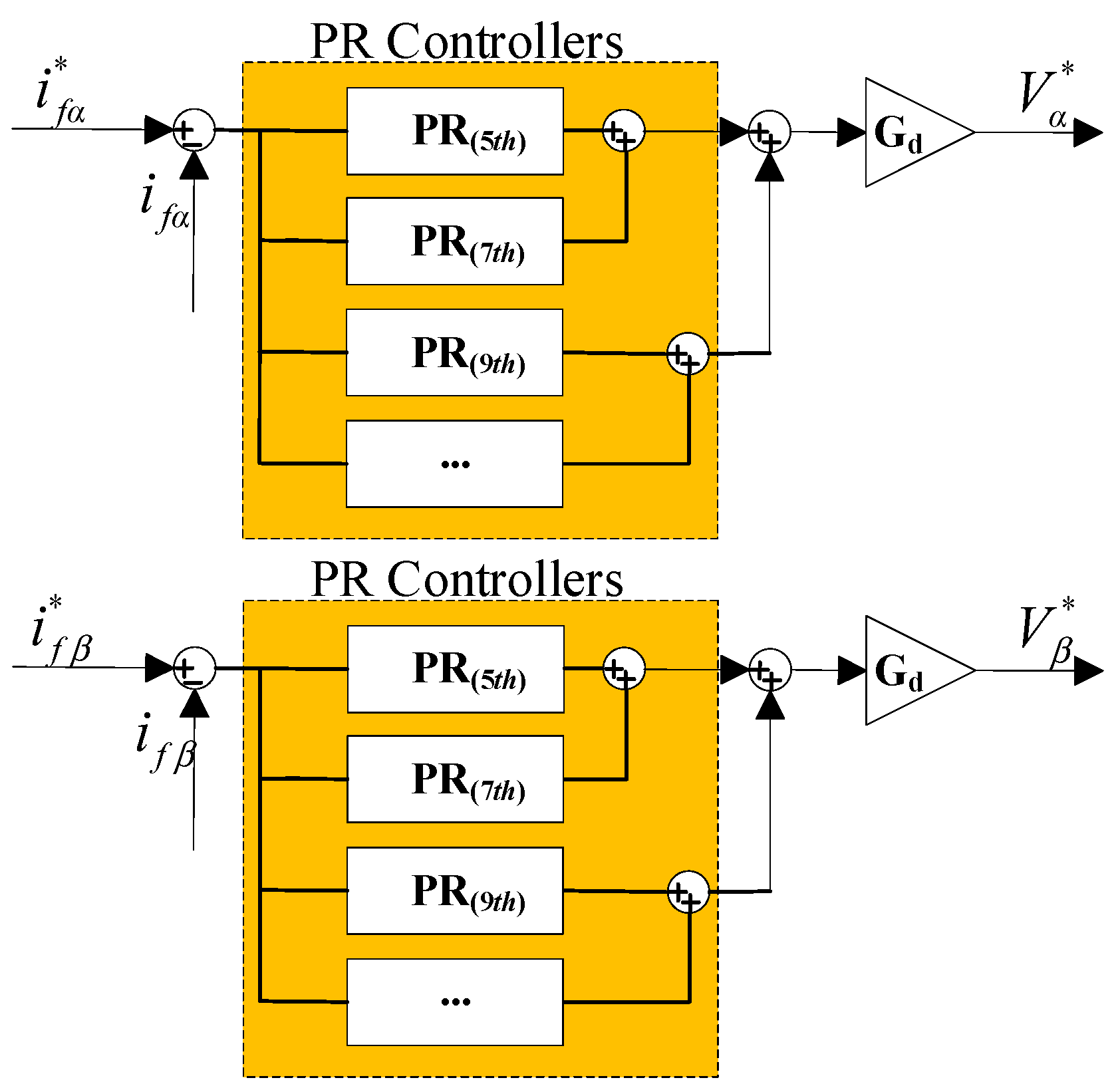
  • Reduced PR controller demand through instantaneous power theory: Instead of assigning a dedicated PR controller for each harmonic order, the proposed method performs harmonic compensation through instantaneous power theory, with only a single PR controller used for tracking the fundamental frequency current. The compensation effect for higher-order harmonics is achieved indirectly through accurate shaping of the inverter current. This reduces controller count and computational burden while maintaining effective multi-order harmonic suppression.
The remainder of the paper is organized as follows: Section 2 presents the system topology and mathematical modeling of the APF; Section 3 details a PLL-less load current sensorless improved PR control; Section 4 provides simulation results; Section 5 discusses experimental validation; and Section 6 concludes the paper.

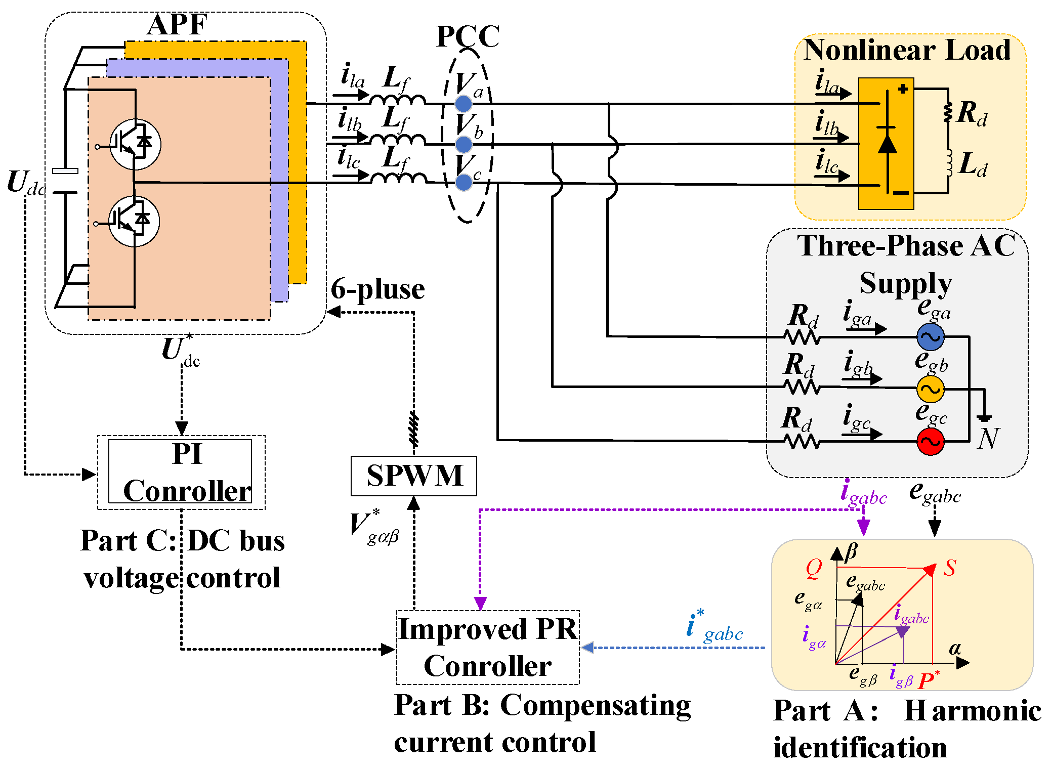
2. APF Control System

As illustrated in Figure 1, the APF system comprises three main components: a three-phase AC source, a three-phase inverter, and a nonlinear load. The point of common coupling (PCC) denotes the interconnection point among these elements. The inverter-side filter inductance is denoted by Lf. The variables ega, egb, and egc represent the three-phase grid voltages, while iga, igb, and igc correspond to the grid currents. The inverter output currents are indicated by ifa, ifb, and ifc, and the nonlinear load currents by ila, ilb, and ilc. Udc denotes the DC-link voltage of the inverter.
The control structure of this system is shown in Figure 1, which includes three parts: harmonic identification (Part A), compensating current control (Part B), and DC bus voltage control (Part C). Part A is responsible for extracting the harmonics and reactive components in the load current and generating the target reference current; Part B uses an improved PR controller to control the inverter output current to track the reference value to achieve harmonic compensation; and Part C uses a PI controller to adjust the DC side voltage to maintain its stability to ensure the energy support required for compensation. The control structure shown in Figure 1 abandons the direct measurement of the load-side and inverter-side current in the traditional method. The core is to use only the grid voltage and grid current information for harmonic identification and compensation command generation, thereby significantly reducing the number of sensors and improving the system robustness.
In a three-phase system, define f(t) as the three-phase grid voltage and current, and the components after Clark coordinate transformation are represented by α, β, and 0, where T is the Clark transformation coordinate, as shown in Formula (1).
f α t f β t f 0 t = T f A t f B t f C t , T = 2 3 1 1 / 2 1 / 2 0 3 / 2 3 / 2 2 / 2 2 / 2 2 / 2
In a three-phase three-wire system, the circuit impedance of the zero component is infinite, so the zero component can be ignored in both voltage and current. Therefore, the voltage and current can be represented by equivalent complex values, as shown in Formula (2). Furthermore, according to the Fourier transform principle and the instantaneous power theory proposed in Reference [16], the instantaneous complex power s, active power p, and instantaneous reactive power q of the fundamental wave can be expressed as in Formula (3), where e* is the conjugate component of e.
e = e α + j e β i = i α + j i β
s = e * × i = p + j q , p = Re ( e * × i ) , q = Im ( e * × i )
The working principle of the APF’s harmonic control function is as follows: First, the sampling circuit acquires signals such as the three-phase grid voltage, load current, and inverter output current. These signals are then transformed from the abc coordinate system to the αβ or dq reference frame via coordinate transformation to enable decoupled control. Next, a harmonic detection algorithm based on the instantaneous power theory is employed to accurately decompose the load current into the fundamental active component—representing the desirable grid current to be retained—and the harmonic/reactive component, which corresponds to the undesired current to be eliminated. Meanwhile, the outer voltage control loop of the DC-link capacitor regulates the charging and discharging processes through a PI controller, thereby stabilizing the DC bus voltage and generating the reference signal for the inner current control loop. The harmonic current compensation module subsequently tracks the target harmonic component in real time using a zero steady-state error tracking algorithm. The accuracy and dynamic performance of this algorithm are critical to the overall compensation effectiveness. Finally, the system generates gating signals via sinusoidal pulse-width modulation (SPWM), and after power amplification and high-frequency filtering, injects a compensation current—equal in amplitude and opposite in phase to the detected harmonic—into the grid. This process achieves dynamic harmonic suppression and active reactive power compensation, thereby enhancing power quality and ensuring the safe operation of the power system.
Since the load current ilabc, the inverter compensation current ifabc, and the grid current igabc are connected in parallel at the same node, Formulas (4) and (5) can be obtained based on the law of charge conservation. Formula (4) reflects the node balance relationship of the current at the PCC, that is, the load current ilabc is equal to the grid current igabc plus the inverter compensation current ifabc. In order to achieve effective compensation of harmonics and reactive currents, the load current needs to be further split into three orthogonal components according to frequency and power characteristics, fundamental active component (il-fp), fundamental reactive component (il-fq), and higher harmonic component (il-h), as shown in Formula (5). Among them, il-fp is the “effective electric energy” that the grid needs to transmit, while il-fq and il-h belong to “ineffective work” and should be compensated by APFs.
i f a b c + i g a b c = i l a b c
i l a b c = i l - f p + i l - f q + i l - h
Therefore, the inverter output current is regulated to contain the fundamental reactive component il-fq and the harmonic component il-h of the load current such that the grid-side current consists solely of the remaining fundamental active component il-fp. In other words, the APF injects harmonic and reactive currents into the grid to counteract the corresponding components at the load side, thereby retaining only the fundamental active current in the grid-side current. This principle enables the APF to perform harmonic suppression and reactive power compensation on the load side, as expressed in Formulas (6) and (7).
i f a b c = i l - f q + i l - h
i g a b c = i l a b c i f a b c = i f p
Therefore, according to Formula (2) and Fourier transform, based on power conservation, Formula (8) can be obtained:
p = p 1 + n = 2 p n , q = q 1 + n = 2 q n
p1 and q1 represent the active and reactive power derived from the interaction between the fundamental components of the grid voltage and grid current, while pn and qn correspond to power components at other (non-fundamental) frequencies. Among them, p1 is the power component that is intended to be retained on the grid side.
Based on Clarke transformation and instantaneous power theory, this section discusses a mathematical model of a parallel active filter and clarifies the coupling relationship between voltage, current, and instantaneous power theory.

3. A PLL-Less Load Current Sensorless Improved PR Control

In order to achieve high-precision compensation of harmonics and reactive components of parallel active power filters under complex working conditions, the previous section discussed the mathematical model and operation mechanism of APF from the perspective of system structure and instantaneous power theory and clarified the key role of reference current generation in filtering performance. However, traditional control strategies generally rely on voltage/current sensors (especially load-side current) and PLLs for coordinate transformation, which results in complex system structures and limited real-time and robustness. To overcome the above problems, this paper proposes an improved PR control strategy, the core feature of which is that no PLL or load-side current sensor is required, and only the grid-side voltage and current signals are used to achieve dynamic tracking of reference current and harmonic compensation.
This section will carry out the design and analysis around the core modules of the strategy, mainly including the calculation method of reference current, the PR controller structure, and the parameter tuning process based on root locus and frequency domain analysis methods.

3.1. PLL-Less Load Current Sensorless Strategy

Figure 2 illustrates the reference current generation process based on the instantaneous power theory [16]. In the proposed method, the grid-side current igabc and grid-side voltage egabc are used as inputs to calculate the instantaneous active power p and reactive power q of the system. The active power p is decomposed into the fundamental active component p1 and the higher-order active component pn for n ≥ 2. To extract the component requiring compensation, a low-pass filter (LPF) is employed to isolate p1 from p. Subsequently, p1 is subtracted from the total active power p, and the output pd from the DC bus voltage controller is added to form the desired active compensation command: p* = pp1 + pd. Considering that this study aims to minimize reactive power, the reactive compensation command is set to q = 0. Finally, the compensation reference current iresf is calculated using the inverse formula of instantaneous power theory, based on the desired power commands p and q, along with the αβ components of the grid voltage egabc.
i r e s f = p + j q / e g a b c *
This reference current will be used as a tracking target in the subsequent PR controller to achieve real-time compensation of harmonics and reactive current.
The enhanced harmonic suppression capability of the proposed method is theoretically supported by the application of instantaneous power theory. Instead of relying on load current measurements, the method utilizes only grid-side voltage and current to compute the total instantaneous power. A low-pass filter is then applied to extract the fundamental active power component, which is used to reconstruct the ideal grid current that should be delivered. The difference between this ideal reference and the actual grid current inherently contains harmonic and reactive components, which are subsequently compensated by the PR controller through closed-loop tracking.

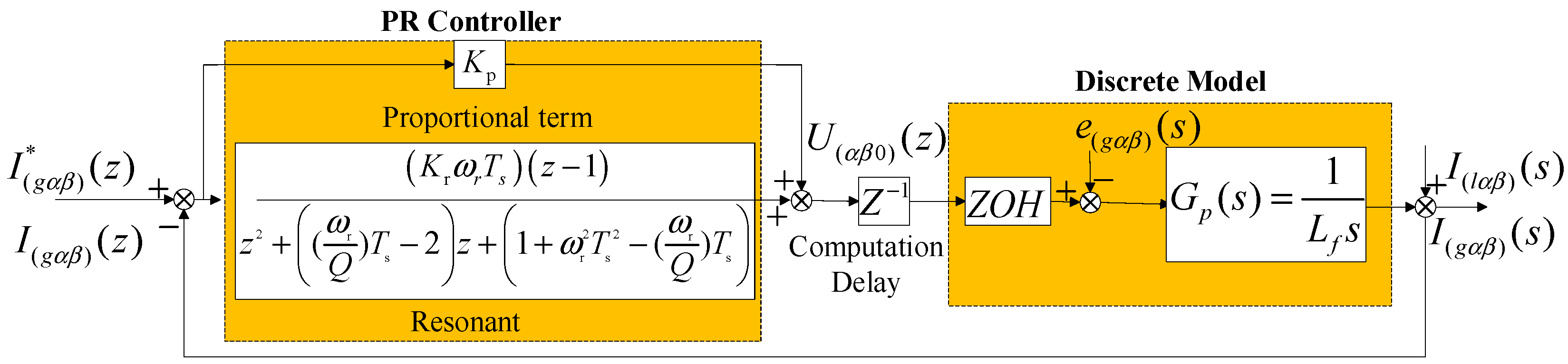
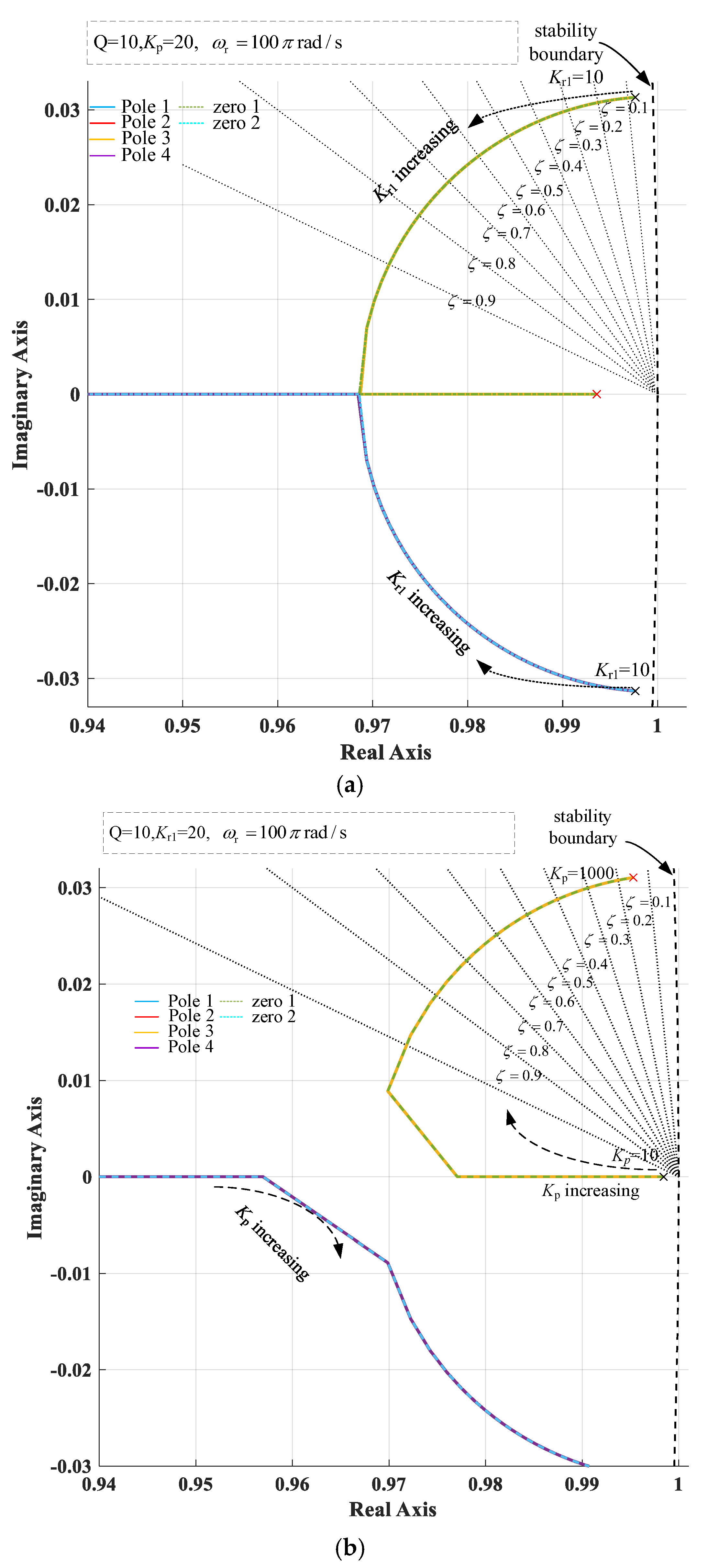
3.2. PR Controller Parameter Design

Furthermore, by eliminating the phase-locked loop (PLL), the proposed strategy avoids the phase detection delays commonly introduced by synchronous coordinate transformation. Since the control is performed directly in the stationary αβ reference frame, the system exhibits faster reaction to disturbances and improved robustness under frequency variations, without additional signal processing overhead.
In APF, the design of the current controller plays a decisive role in the compensation performance. The PR controller has become the core solution in sinusoidal quantity tracking because of its infinite gain capability at the resonant frequency. This section will start with the principle of the classic PR controller and combine Reference [24] to propose a new PR control that only targets the fundamental frequency AC component to improve the system’s harmonic suppression capability under dynamic load conditions.
According to References [24,25,26], the classical PR controller is given in Formula (10), and its mathematical derivation can be found in more detail in Reference [13]:
C cos ( s ) = K p + K r ω 0 s s 2 + ω 0 2
Kp is the proportional gain, Kr is the resonant gain, and ω0 = 2πf0 is the resonant frequency. The gain at the resonant frequency can theoretically be infinite. But a very high gain tends to reduce the phase margin (PM) and robustness of the system. However, the gain of the resonant term must be high enough to achieve zero or quasi-zero steady-state error. Therefore, the quality factor Q is introduced to balance the gain and phase margin at the resonant frequency. The PR controller can be further written as Formula (11):
C ( s ) = K p + K r ω 0 s s 2 + ( ω 0 / Q ) s + ω 0 2
The Q value affects the bandwidth at the resonant frequency. According to Reference [25], the higher the Q value, the higher the gain at the resonant frequency and the narrower the passband region near the frequency. A lower Q value will result in a lower gain, so there will be some steady-state errors. In order to accurately locate the zero point of the resonant term, K1 is introduced in the design to fine-tune the zero point position. The PR controller can be further written as Formula (12):
C ( s ) = K p + K r 1 ω 0 s K 1 ω 0 2 s 2 + ( ω 0 / Q 1 ) s + ω 0 2
As shown in Figure 3, the traditional PR control method requires configuring and tuning a dedicated PR controller for each harmonic order—for example, the fifth and seventh harmonics must be compensated by separate controllers. This results in a complex control architecture with increased computational burden and the need for additional hardware, such as PLL modules and load-side current sensors.
In contrast, the proposed method achieves significant structural simplification. It eliminates the PLL and load-side current sensors entirely and uses only a single PR controller focused on the fundamental frequency. Harmonic compensation is achieved indirectly through precise tracking of a reference current derived from instantaneous power theory using grid-side voltage and current signals. This approach not only reduces implementation complexity and tuning effort, but also improves system robustness, noise immunity, and cost efficiency.
In order to make the controller realizable in actual digital control systems, it needs to be discretized. Using the forward rectangular method [26], the discrete form of the PR controller is
C ( z ) = K p + A z + B z 2 + C z + D
A = K r 1 ω 0 T s ,   B = K r 1 ω 0 T s K 1 ω 0 2 T s 2 ,   C = ( ω 0 / Q ) T s 2 ,   D = 1 + ω 0 2 T s 2 ( ω 0 / Q ) T s
where Ts is the sampling period. In this form, the controller maintains high gain at the frequency ω0 and has low implementation complexity, which is suitable for control platforms such as FPGA/DSP.
Considering that the switching behavior of the PWM inverter can be approximated as a zero-order keeper, its control loop can be modeled as a discrete closed-loop system including a PR controller, PWM delay, and filter structure. Figure 4 shows the discrete block diagram of the compensation current control loop based on αβ axis equivalent modeling.
Through this discrete model, the closed-loop transfer function of the system is constructed as Formula (15):
I ( α β 0 ) ( z ) I ( α β 0 ) * ( z ) = K p L c T s ( z 2 + ( C + A K p ) z + ( D A K p ) ) z 4 + ( C 1 ) z 3 + K p L c T s + D C z 2 + K p L c T s C + L c T s A D z + K p L c T s D L c T s A
According to Reference [24], the quality factor Q can be set to 10, and the resonant frequency should be chosen as the fundamental frequency of 50 Hz. Therefore, the primary parameters to be determined are Kp and Kr1. The proportional gain Kp plays a critical role in the transient response, while the resonant gain Kr1 influences the location of the system’s zeros, thereby affecting the root locus trajectory. Consequently, the root locus diagram is plotted based on Formula (15) to guide the selection of appropriate Kp and Kr1 values. Figure 5 illustrates the root locus diagrams used to guide the selection of the proportional gain Kp and resonant gain Kr1 in the improved PR controller design.
The transfer function shown has two zeros (Zero1 and Zero2) and four poles (Pole1 to Pole4). The design mainly considers the root locus distribution between Zero1 and Pole1 [24] to guide the selection of Kp and Kr1 to ensure that the system is stable and has good dynamic performance. Analyzing Figure 5a, with Kp = 20 fixed and Kr1 increased (from 10 to 1000), the root locus tends to move from left to right. With two zeros fixed, the poles gradually approach the unit circle boundary (about 0.99) from the left. Too large a Kr1 (as shown in the figure, Kr1 = 1000 corresponds to the red cross position) will cause the poles to be very close to the unit circle, and the system tends to be unstable or overshoot. Therefore, Kr1 ∈ [10, 100] is more appropriate. At this time, the system responds faster, the poles are still within the unit circle, and they have a good phase margin. Similarly, we analyze Figure 5b, with Kr1 = 20 fixed; as Kp increases, the poles gradually approach the unit circle boundary along the curve, the response speed increases, but at the same time the system stability decreases. The red cross (Kp = 1000) in the figure is already very close to the unit circle, near the stability boundary, and has a high risk of overshoot. Therefore, Kp ∈ [10, 100] is more appropriate. At this time, the system responds faster, the poles are still within the unit circle, and they have a good phase margin.
This section proposes a design method for an improved PR controller. Based on the reference current extraction method of the instantaneous power theory of the grid-side voltage and current, the grid-side current only needs to track the baseband active command current without configuring a separate controller for each harmonic. Compared with the traditional method, the proposed method significantly simplifies the controller design and system structure by using a single PR controller to compensate for all harmonics, reduces the computational burden, and improves the dynamic response and steady-state accuracy of the system. Through discrete modeling and root locus analysis, this section further explores the influence of proportional gain Kp and resonant gain Kr1 on the pole distribution and stability of the system and proposes the optimal parameter selection range of Kp ∈ [10, 100] and Kr1 ∈ [10, 100]. This design method effectively improves the tracking accuracy and dynamic compensation performance of the reference current and ensures the stability of the system.

4. Simulation Verification

In order to verify the actual compensation performance of the improved PR controller proposed in Section 3, this section builds a two-level parallel APF model based on the MATLAB/Simulink 2022b simulation platform and compares and analyzes the performance of the proposed control strategy under steady-state and dynamic conditions. The controller structure and parameter settings are determined based on the design and root locus analysis results completed in the previous section. The simulation parameters are a grid voltage of 380 V rms/50 Hz, a switching frequency of 20 kHz, a sampling frequency of 20 kHz, an equivalent inductance L of 1 mH, Udc = 800 V, and nonlinear loads used uncontrolled diode rectifier bridges.

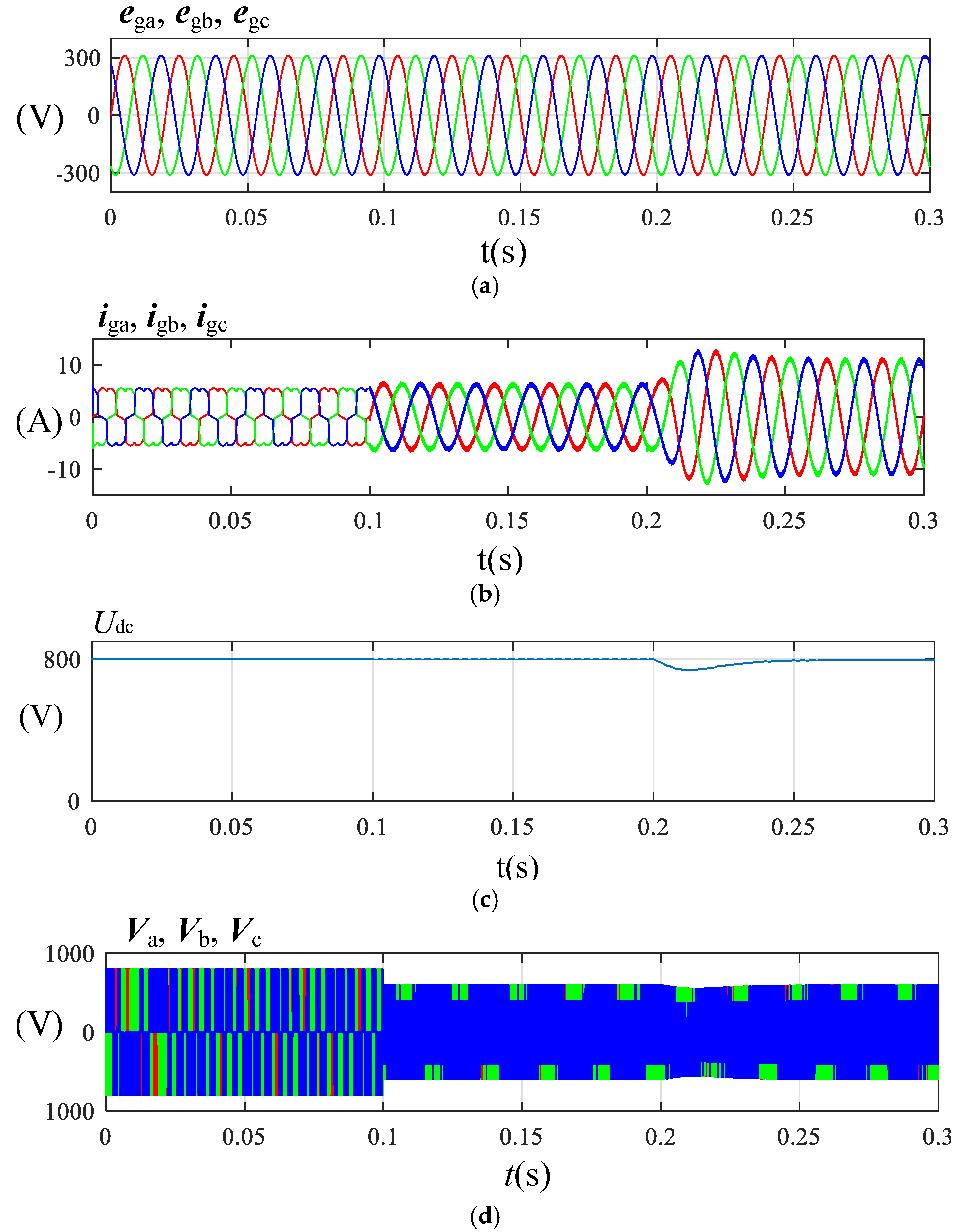
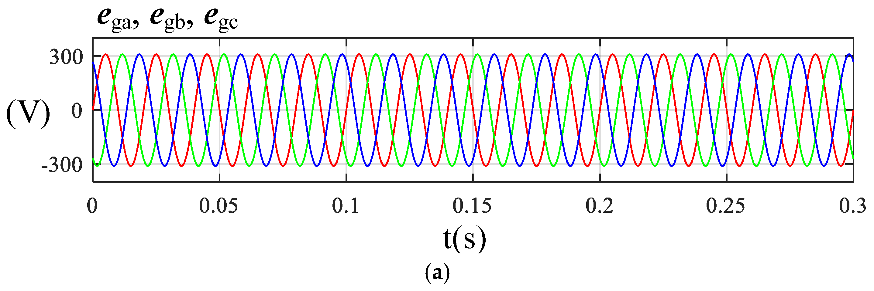
4.1. Traditional PR Control Simulation Analysis

For comparative verification, this paper reproduces the traditional PR control strategy based on PLL and coordinate transformation described in [27]. The proposed method transforms the harmonic command current into the dq coordinate system, converting adjacent odd harmonics into even harmonics, thereby reducing the number of PR controllers. For example, the third and fifth harmonics are uniformly converted into the fourth harmonic. Four groups of PR controllers are used in the simulation, corresponding to the 6th, 10th, 14th, and 18th harmonics, respectively, which indirectly suppress the main odd harmonics (5th to 19th).
Figure 6 shows the simulation waveform of the traditional PR control strategy under steady-state conditions. When the APF was put into operation at t = 0.1 s, the total harmonic distortion (THD) of the grid current dropped rapidly from the initial 28% to 4.5%, indicating that the control strategy has good harmonic suppression capability under steady-state conditions. Figure 6e further provides a spectrum analysis of the grid current, showing that the main low-order harmonics have been effectively suppressed.
To further verify the dynamic performance of the control strategy, Figure 7 shows the load being suddenly reduced from 120 Ω to 60 Ω at t = 0.2 s to simulate a load mutation. In Figure 7, at the moment of load mutation, the grid current waveform does not show obvious overshoot, and the system recovers to a new steady state within about 20 ms, reflecting good dynamic response characteristics. The THD of the grid current before and after the mutation is 4.5% and 2.6%, respectively. The spectrum analysis corresponding to the current after the mutation is shown in Figure 7e, which further verifies the effectiveness of the control strategy under dynamic conditions.
However, the traditional PR control strategy needs to design multiple PR controllers during implementation to compensate for different harmonics. For example, to suppress harmonics from the 5th to the 19th order, individual PR controllers must be configured for the 6th, 10th, 14th, and 18th harmonics. This significantly increases system complexity and computational burden. In addition, the strategy also requires the installation of a current sensor on the load side to detect the current and the use of a PLL to extract the phase information of the current. However, the PLL has the characteristic of slow response speed, especially when the frequency changes suddenly or the system is disturbed; its dynamic response performance is poor, affecting the overall performance of the system.

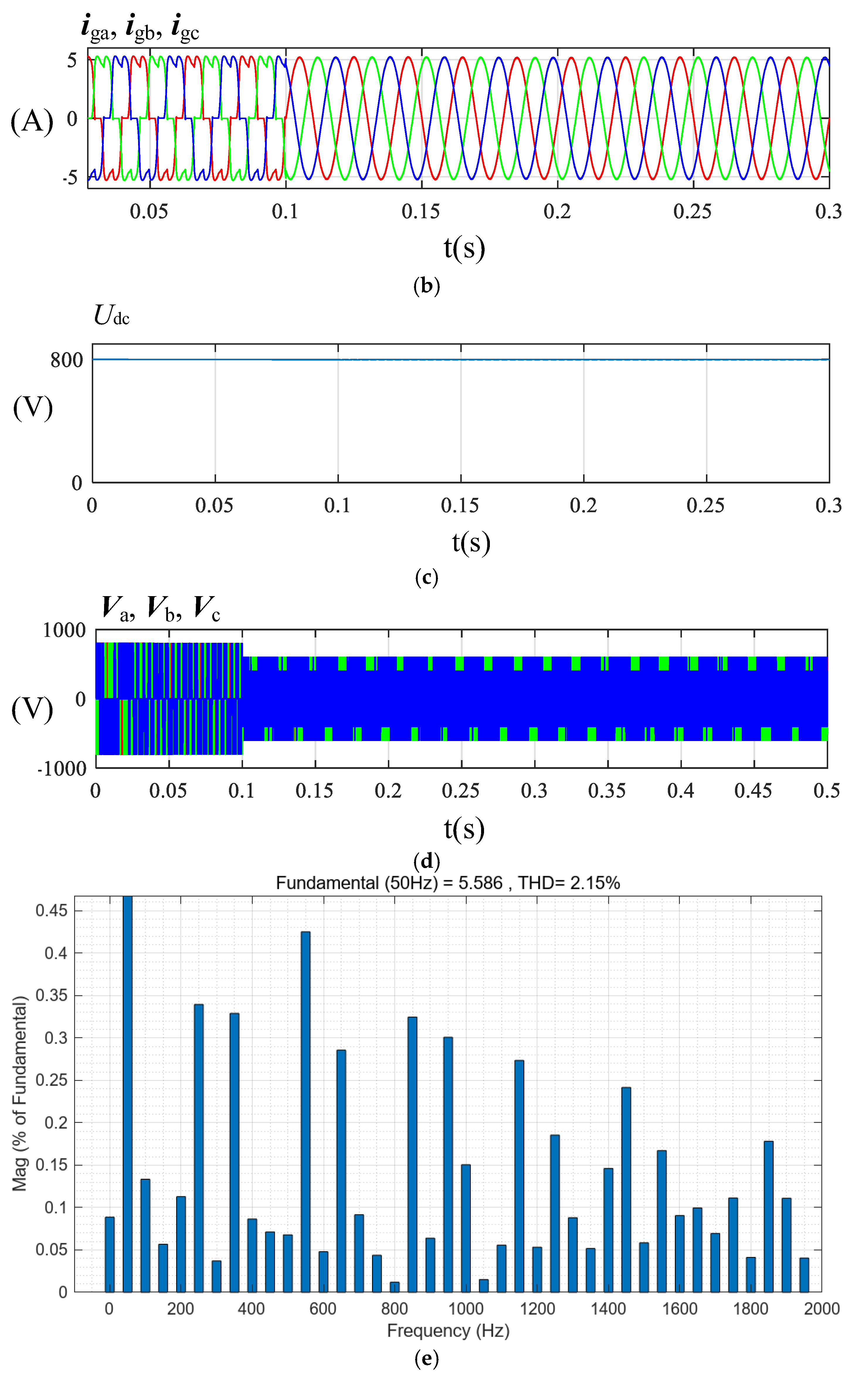
4.2. Simulation Analysis of Proposed PR Control Method

In the simulation, the proposed PR controller adopts a single-frequency resonant structure with the resonant frequency set to 50 Hz. The proportional gain Kp is set to 20, the resonant gain Kr to 150, the quality factor Q to 10, and the sampling period Ts to 50 μs. These parameter settings are based on the root locus analysis presented in Section 3 and are intended to ensure system stability while achieving satisfactory reference current tracking and harmonic compensation performance.
Figure 8 shows the simulation waveform of the proposed PR control strategy under steady-state conditions. After the APF was put into operation at t = 0.1 s, the THD of the grid current dropped rapidly from the initial 28% to 2.3%, further improving the harmonic suppression effect compared with the traditional PR control method (4.5%). Figure 8e further provides a spectrum analysis of the grid current, showing that the main low-order harmonics have been effectively suppressed
To evaluate the performance of the proposed control strategy under dynamic conditions, Figure 9 shows the load being suddenly reduced from 120 Ω to 60 Ω at t = 0.2 s to simulate a load mutation. As can be seen from Figure 9, the grid current waveform remains stable at the moment of load mutation, without significant overshoot, and the system quickly converges to a new steady state within about 15 ms, reflecting that the proposed control strategy has excellent dynamic response performance. The THD of the grid current before and after the mutation is 2.3% and 1.8%, respectively. The corresponding spectrum analysis is shown in Figure 9e, which further verifies the effectiveness of the control strategy under dynamic conditions.
The proposed PR control strategy simplifies the control structure by eliminating multiple harmonic-specific PR controllers, the PLL module, and load-side current sensors. This reduces system complexity and computational burden, enhances dynamic response and robustness, and allows accurate control using only grid-side measurements—ultimately lowering hardware cost and easing system maintenance.

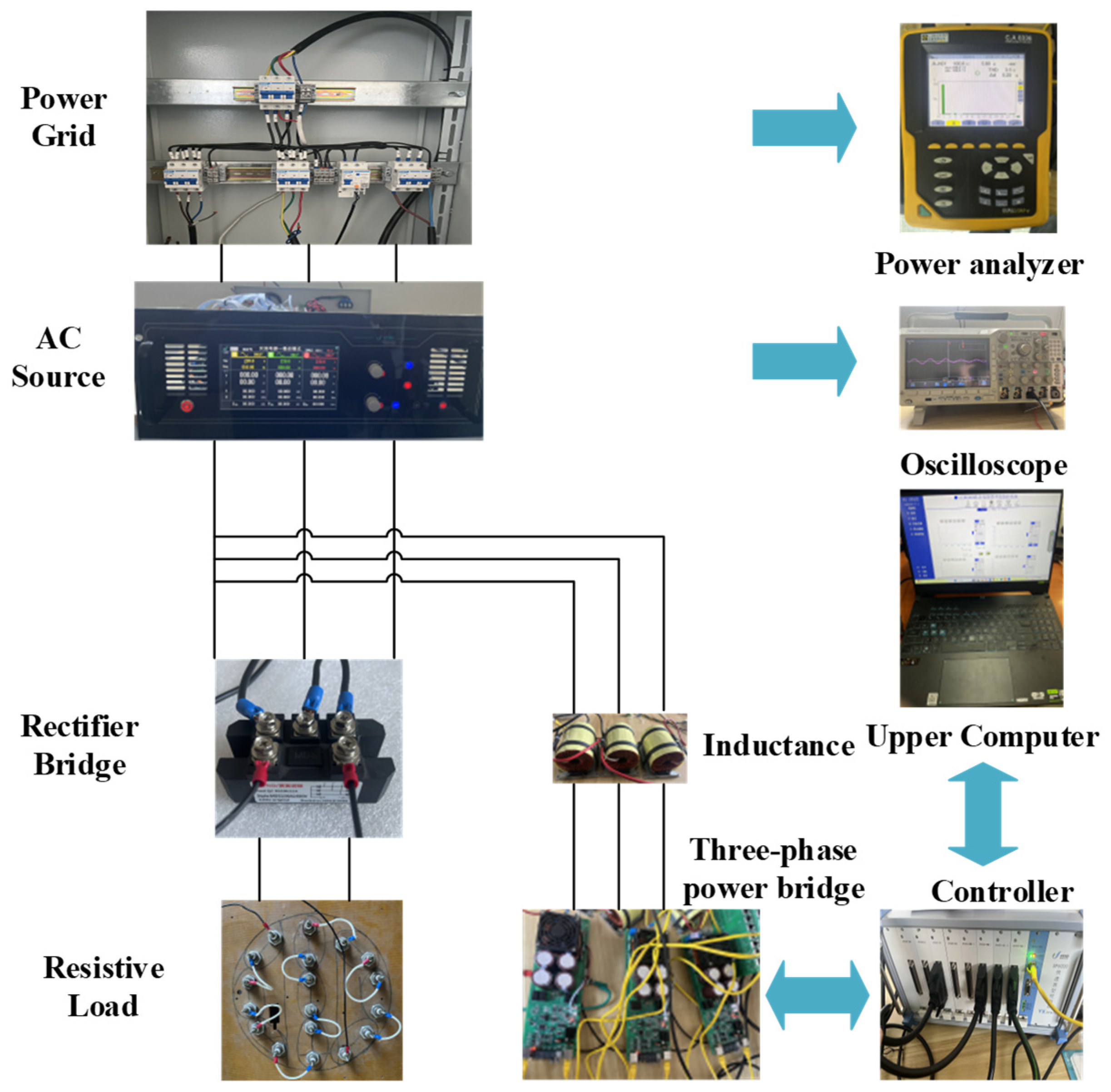
5. Experimental Verification

Based on the completed simulation verification, a 1 kVA two-level parallel APF experimental platform was established, as shown in Figure 10, with detailed system parameters listed in Table 1. The platform employs the YXSPACE-SP6000 controller and the YXPHM-MMCFB01 series inverter. The three-phase AC voltage source is provided by YXACS15-YZ, while a rectifier bridge and power resistors are used as nonlinear loads. The DC side utilizes capacitors to maintain a stable voltage.

5.1. Analysis of Traditional PR Control Experiments

Figure 11 shows the current and voltage waveforms of the grid under the traditional PR control algorithm in a steady state. Figure 11a shows the voltage and current waveforms of phase A. After the filter is put into operation, the current basically achieves unity power factor operation, indicating that the controller has a certain steady-state tracking capability. Figure 11b shows the three-phase grid current. The overall trend is close to sinusoidal, but obvious high-frequency ripple and asymmetry can be seen, indicating that the proposed method still has large current fluctuations in the steady state; the THD reaches 6.2%. As shown in Figure 11c, the current spectrum still contains multiple low-order harmonic components. This result shows that in the steady state of the grid, the traditional PR control algorithm can guarantee the power quality to a certain extent.
To assess transient performance, this study drops the load from 120 Ω to 80 Ω at t = a to simulate the load mutation. Figure 11d shows that the grid current exhibits no significant overshoot during the transition, and the waveform stabilizes within approximately one cycle (20 ms). Although minor fluctuations are present during the transient, the system successfully returns to steady operation without triggering protective responses. Overall, the traditional PR control method demonstrates basic compensation capability under dynamic conditions. However, it requires multiple PR controllers for different harmonics, a PLL for phase tracking, and load-side current sensors to generate the compensation reference. These hardware and computational requirements increase the complexity and reduce the flexibility of the system, especially in fast-changing grid conditions.
In general, the traditional PR control can achieve basic current tracking and harmonic compensation under steady-state conditions, but there are still problems such as steady-state error, and the transient response speed can be improved. At the same time, the proposed method relies on the PLL to extract the current phase and requires the use of a load-side current sensor, which is not conducive to economic efficiency.

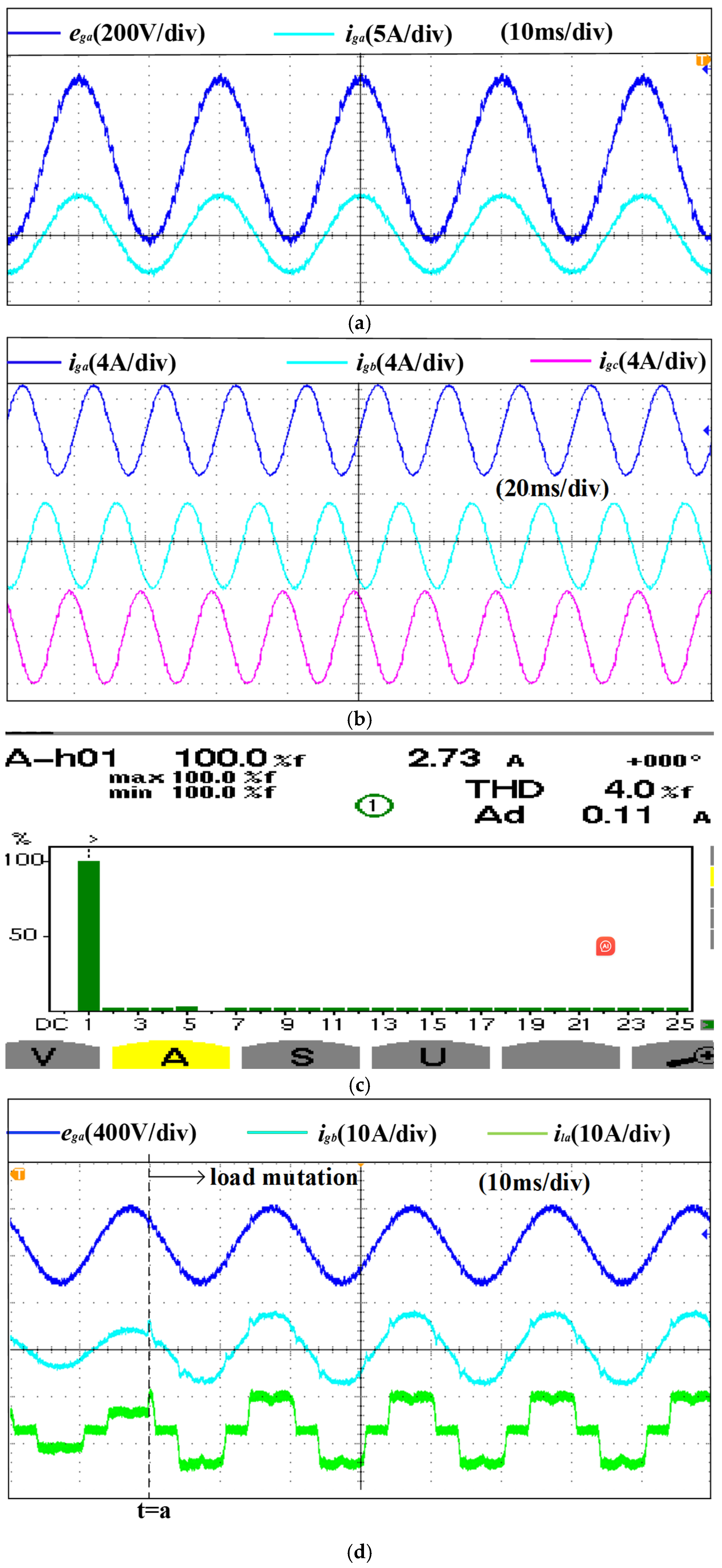
5.2. Analysis of Proposed PR Control Experiment

Figure 12 shows the current and voltage waveforms of the grid under the PR control algorithm proposed in this paper under steady-state conditions. Figure 12a shows the grid phase A voltage and grid phase A current. It can be seen that the compensated grid current operates at unity power factor. Figure 12b shows the three-phase current waveform, which has good overall symmetry, greatly reduced ripple, and significantly weakened harmonic components. Figure 12c shows the steady-state current FFT, and the THD is reduced to 4.0%, which is 2.2% lower than the traditional method, verifying the enhanced harmonic suppression capability. This result shows that under the steady state of the grid, the proposed improved PR control algorithm can guarantee the power quality to a certain extent.
To further verify the dynamic performance of the control strategy, this study drops the load from 120 Ω to 60 Ω at t = a to simulate the load mutation. Figure 12d shows the grid current and load current waveforms of the load mutation under the algorithm proposed in this paper. At the moment of mutation, the load changes from about 120 Ω to 80 Ω. The current does not overshoot at the moment of disturbance. The response process is smooth and oscillatory. The current waveform quickly tends to the new steady state, reflecting the high adaptability and strong robustness of the controller to the mutation conditions, effectively avoiding the risk of triggering the protection device due to overshoot current in traditional APF, and significantly improving the operating reliability of the system under dynamic conditions.
While the traditional PR control achieves basic compensation performance, it requires multiple harmonic-specific PR controllers, a PLL, and load-side current sensors to realize real-time control. In contrast, the proposed method eliminates PLL and load-side current sampling and can achieve precise regulation only through grid-side current closed-loop control, greatly simplifying the control structure. It does not require multiple sets of harmonic compensation PR controllers, reducing implementation complexity and computing resource consumption.

6. Conclusions

This paper proposes a harmonic compensation strategy without load current sensors based on instantaneous power and an improved PR controller. The proposed method is validated through both simulation and experimental platforms. Compared with conventional three-phase two-level APF control strategies, the proposed approach offers the following features and advantages:
(1)
The proposed reference current generation method eliminates the need for load-side current sensors and relies solely on grid voltage and current measurements. This avoids the dependence on load-side signals inherent in traditional methods, thereby reducing sensor count and improving cost efficiency.
(2)
A control strategy that operates without a PLL is developed, eliminating the need for synchronous coordinate transformation. This enhances the system’s robustness against frequency fluctuations and PLL-related errors.
(3)
The proposed parameter tuning approach does not rely on empirical adjustment. Instead, it is grounded in discrete domain modeling and root locus analysis, offering a quantifiable and visually guided method for controller design.
(4)
The proposed harmonic compensation scheme eliminates the need to design individual PR controllers for each harmonic order. By integrating an instantaneous power theory with a single set of fundamental PR controllers, multi-order harmonic compensation can be achieved, thereby reducing computational complexity and resource consumption.

Author Contributions

Conceptualization, methodology, writing—original draft preparation and visualization, J.L.; validation and supervision, W.Y. formal analysis, Y.Z.; investigation, J.Z.; data curation, X.Z. All authors have read and agreed to the published version of the manuscript.

Funding

This work was supported in part by the Beijing Natural Science Foundation (3232051), in part by the Beijing Natural Science Foundation (L244005), and in part by Fundamental Research Funds for the Central Universities (2024ZKPYJD07).

Institutional Review Board Statement

Not applicable.

Informed Consent Statement

Not applicable.

Data Availability Statement

The MATLAB/Simulink simulation models and experimental data used in this study are available from the corresponding author upon reasonable request. All raw data supporting the findings are presented in the figures and tables within the manuscript.

Conflicts of Interest

The authors declare no conflicts of interest.

References

  1. Jiang, X.; Yi, H.; Zhuo, F.; Li, Y. A Stabilization Strategy Based on Grid Current Feedforward for the Harmonic Oscillation of APF System. IEEE J. Emerg. Sel. Top. Power Electron. 2024, 12, 2116–2129. [Google Scholar] [CrossRef]
  2. Upanya, M.; Anushree, S.; Masood, M.; Deekshitha, G.N.; Kumara, K.P.N. Harmonic Mitigation Using Active and Passive Filters. In Proceedings of the 2025 International Conference on Sustainable Energy Technologies and Computational Intelligence (SETCOM), Gandhinagar, India, 21–23 February 2025; pp. 1–6. [Google Scholar] [CrossRef]
  3. Li, Y.; Yi, H.; Zhuo, F.; Jiang, X. Harmonic Oscillation and Stabilization Strategy of Source-Current-Detected Shunt APF Considering Interaction with Nonlinear Load and Grid Impedance. IEEE J. Emerg. Sel. Top. Power Electron. 2024, 12, 420–430. [Google Scholar] [CrossRef]
  4. Woo, D.; Kim, S. Accurate Harmonic Current Control for Large-Capacity LCL-Type Active Power Filter with Inverter-Side Current Feedback. IEEE Trans. Ind. Appl. 2025, 61, 4065–4078. [Google Scholar] [CrossRef]
  5. Fei, J.; Wang, J.; Zhang, L. Complementary Sliding Mode Control Using Petri Probabilistic Fuzzy Recurrent Neural Network for Active Power Filter. IEEE Trans. Autom. Sci. Eng. 2025, 22, 8108–8122. [Google Scholar] [CrossRef]
  6. Yan, Q.; Zhang, L.; Zhao, R.; He, J.; Guo, L.; Zhang, Z. A Paralleled Current and Voltage Control Strategy with Compound PI Controllers for Three-Phase Active Power Filters. IEEE Trans. Power Electron. 2024, 39, 6989–7001. [Google Scholar] [CrossRef]
  7. Ou, M.; Zou, J.; Liu, Q.; Yang, H. A Dual-Loop Control Strategy Based on PI and Repetitive Control for APF with CoolSiC™ MOSFET. In Proceedings of the 2023 6th International Conference on Electrical Engineering and Green Energy (CEEGE), Grimstad, Norway, 6–9 June 2023; pp. 29–34. [Google Scholar] [CrossRef]
  8. Dong, X.; Li, H. Model Predictive Control for A PLL-Less SiC Grid-Tied Inverter with Zero-Voltage-Ride-Through Capability. In Proceedings of the 2022 IEEE Energy Conversion Congress and Exposition (ECCE), Detroit, MI, USA, 9–13 October 2022; pp. 1–7. [Google Scholar] [CrossRef]
  9. Mishra, M.K.; Mishra, A.; Lal, V.N. An Advanced PLL-less Control Scheme for LVRT Capability with Harmonics Current Mitigations in Grid-Tied PV System Under Weak and Distorted Grid. In Proceedings of the 2022 IEEE Applied Power Electronics Conference and Exposition (APEC), Houston, TX, USA, 20–24 March 2022; pp. 1298–1304. [Google Scholar] [CrossRef]
  10. Bacon, V.D.; de Souza, V.; Padim, E.T.; da Silva, S.A.O. Influence of the PLL phase-angle quality on the static and dynamic performance of grid-connected systems. In Proceedings of the 2017 Brazilian Power Electronics Conference (COBEP), Juiz de Fora, Brazil, 19–22 November 2017; pp. 1–6. [Google Scholar] [CrossRef]
  11. Parvez, M.; Elias, M.F.M.; Rahim, N.A.; Blaabjerg, F.; Abbott, D.; Al-Sarawi, S.F. Comparative Study of Discrete PI and PR Controls for Single-Phase UPS Inverter. IEEE Access 2020, 8, 45584–45595. [Google Scholar] [CrossRef]
  12. Gupta, R.K.; Jena, S.; Babu, B.C. Analysis of PR controller for eliminating double frequency oscillations in DC-link of 3-Φ shunt APF during source disturbances. In Proceedings of the 2013 Students Conference on Engineering and Systems (SCES), Allahabad, India, 12–14 April 2013; pp. 1–6. [Google Scholar] [CrossRef]
  13. Sharma, S.; Verma, V. A Brief Review Regarding Sensor Reduction and Faults in Shunt Active Power Filter. In Proceedings of the 2018 2nd IEEE International Conference on Power Electronics, Intelligent Control and Energy Systems (ICPEICES), Delhi, India, 22–24 October 2018; pp. 426–430. [Google Scholar] [CrossRef]
  14. Ribeiro, R.L.A.; Azevedo, C.C.; Sousa, R.M. A non-standard adaptive control for shunt active power filter without current harmonic detection. In Proceedings of the IECON 2010—36th Annual Conference on IEEE Industrial Electronics Society, Glendale, AZ, USA, 7–10 November 2010; pp. 2007–2012. [Google Scholar] [CrossRef]
  15. Nedeljković, D.; Nemec, M.; Drobnič, K.; Ambrožič, V. Active power filter with a reduced number of current sensors. Elektrotehniški Vestn. 2009, 76, 275–280. [Google Scholar]
  16. Wojciechowski, D.; Strzelecki, R. Sensorless predictive control of three-phase parallel active filter. In Proceedings of the AFRICON 2007, Windhoek, South Africa, 26–28 September 2007; pp. 1–7. [Google Scholar] [CrossRef]
  17. Wojciechowski, D. Grid voltages sensorless control system of the PWM rectifier with active filtering function. In Proceedings of the IEEE Compatibility in Power Electronics, Gdynia, Poland, 1–3 June 2005; pp. 238–246. [Google Scholar] [CrossRef]
  18. Zhang, Y.; Wang, Z.; Jiao, J.; Liu, J. Grid-Voltage Sensorless Model Predictive Control of Three-Phase PWM Rectifier Under Unbalanced and Distorted Grid Voltages. IEEE Trans. Power Electron. 2020, 35, 8663–8672. [Google Scholar] [CrossRef]
  19. Ketzer, M.B.; Jacobina, C.B. Nonlinear virtual flux oriented control for sensorless active filters. In Proceedings of the 2013 Brazilian Power Electronics Conference, Gramado, Brazil, 27–31 October 2013; pp. 393–398. [Google Scholar] [CrossRef]
  20. Al-Gahtani, S.F.; Nelms, R.M. Performance of a Shunt Active Power Filter for Unbalanced Conditions Using Only Current Measurements. Energies 2021, 14, 397. [Google Scholar] [CrossRef]
  21. Al-Gahtani, S.; Nelms, R.M. A New Voltage Sensorless Control Method for a Shunt Active Power Filter for Unbalanced Conditions. In Proceedings of the 2019 IEEE International Conference on Environment and Electrical Engineering and 2019 IEEE Industrial and Commercial Power Systems Europe (EEEIC/I&CPS Europe), Genova, Italy, 11–14 June 2019; pp. 1–6. [Google Scholar] [CrossRef]
  22. Alathamneh, M.; Ghanayem, H.; Nelms, R.M. Shunt active power filter voltage sensorless method using a PR controller for unbalanced grid conditions. Energy Rep. 2023, 9 (Suppl. S1), 1056–1064. [Google Scholar] [CrossRef]
  23. Alathamneh, M.; Ghanayem, H.; Nelms, R.M. A Robust Three-Phase Shunt Active Power Filter with Frequency Adaptive PR Controller and Sensorless Voltage Control. In Proceedings of the 2023 IEEE Industry Applications Society Annual Meeting (IAS), Nashville, TN, USA, 29 October–2 November 2023; pp. 1–8. [Google Scholar] [CrossRef]
  24. Santiprapan, P.; Areerak, K.; Areerak, K. An Adaptive Gain of Proportional-Resonant Controller for an Active Power Filter. IEEE Trans. Power Electron. 2024, 39, 1433–1446. [Google Scholar] [CrossRef]
  25. Lenwari, W.; Sumner, M.; Zanchetta, P. The Use of Genetic Algorithms for the Design of Resonant Compensators for Active Filters. IEEE Trans. Ind. Electron. 2009, 56, 2852–2861. [Google Scholar] [CrossRef]
  26. Santiprapan, P.; Areerak, K.; Areerak, K. Proportional plus resonant control for active power filter in unbalanced system. In Proceedings of the 2017 International Electrical Engineering Congress (iEECON), Pattaya, Thailand, 8–10 March 2017; pp. 1–4. [Google Scholar] [CrossRef]
  27. Pan, M.; Xi, Z.; Zhou, M. An Improved PR Controller Current Tracking Control Strategy Research for Active Power Filter; Atlantis Press: Dordrecht, The Netherlands, 2015. [Google Scholar] [CrossRef]
Figure 1. APF system structure and control block diagram.
Applsci 15 07830 g001
Figure 2. Reference current generation flow chart based on instantaneous power theory.
Applsci 15 07830 g002
Figure 3. Traditional PR control.
Applsci 15 07830 g003
Figure 4. A block diagram of the dq0-axis compensation current control loop in the discrete domain.
Applsci 15 07830 g004
Figure 5. Improved PR controller parameter settings: (a) Kr1 root locus diagram; (b) Kp root locus diagram.
Applsci 15 07830 g005
Figure 6. Steady-state situation of traditional PR control: (a) grid voltage, (b) grid current, (c) DC voltage, (d) grid connection point voltage, and (e) FFT of traditional PR control grid current before mutation.
Applsci 15 07830 g006
Figure 7. Traditional PR control load mutation situation: (a) grid voltage, (b) grid current, (c) DC voltage, (d) grid connection point voltage, and (e) FFT of grid current after mutation.
Applsci 15 07830 g007aApplsci 15 07830 g007b
Figure 8. Steady-state situation of proposed PR control method: (a) grid voltage; (b) grid current; (c) DC voltage; (d) grid connection point voltage; (e) FFT of the proposed PR control grid current before mutation.
Applsci 15 07830 g008aApplsci 15 07830 g008b
Figure 9. Load mutation of proposed PR control method: (a) grid voltage; (b) grid current; (c) DC voltage; (d) grid connection point voltage; (e) FFT of grid current after the mutation.
Applsci 15 07830 g009
Figure 10. Experimental platform.
Applsci 15 07830 g010
Figure 11. Steady-state situation of conventional PR control: (a) phase A grid voltage and current; (b) grid current; (c) steady-state current FFT; (d) phase A current mutation.
Applsci 15 07830 g011aApplsci 15 07830 g011b
Figure 12. Steady-state situation of proposed PR control: (a) phase A grid voltage and current; (b) grid current; (c) steady-state current FFT; (d) phase A grid voltage, phase A grid current, and phase A load current.
Applsci 15 07830 g012
Table 1. System parameters for experiment.
ParameterValue
Supply voltage and frequencyeg = 380 V(rms), f = 50 Hz
Active power filter circuitLf = 0.0022 H
C = 1500 µF, Udc = 600 V
Nonlinear loadRL = 120 Ω
Sampling frequencyfs = 20 kHz
Switching frequencyfsw = 20 kHz
Disclaimer/Publisher’s Note: The statements, opinions and data contained in all publications are solely those of the individual author(s) and contributor(s) and not of MDPI and/or the editor(s). MDPI and/or the editor(s) disclaim responsibility for any injury to people or property resulting from any ideas, methods, instructions or products referred to in the content.

