Article

A Hybrid Framework for Metal Artifact Suppression in CT Imaging of Metal Lattice Structures via Radon Transform and Attention-Based Super-Resolution Reconstruction

1
School of Materials, Northwestern Polytechnical University, Xi’an 710072, China
2
AVIC Manufacturing Technology Institute, Beijing 100024, China
*
Author to whom correspondence should be addressed.
These authors contributed equally to this work.
Appl. Sci. 2025, 15(14), 7819; https://doi.org/10.3390/app15147819
Submission received: 28 May 2025 / Revised: 30 June 2025 / Accepted: 10 July 2025 / Published: 11 July 2025

Abstract

High-density component-induced metal artifacts in industrial computed tomography (CT) severely impair image quality and make further analysis more difficult. To suppress artifacts and improve image quality, this research suggests a practical approach that combines lightweight attention-enhanced super-resolution networks with Radon-domain artifact elimination. First, the original CT slices are subjected to bicubic interpolation, which enhances resolution and reduces sampling errors during transformation. The Radon transform, which detects and suppresses metal artifacts in the Radon domain, is then used to convert the interpolated pictures into sinograms. The artifact-suppressed sinograms are then reconstructed at better resolution using a lightweight Enhanced Deep Super-Resolution (EDSR) network with a channel attention mechanism, which consists of only one residual block. The inverse Radon transform is used to recreate the final CT images. An average peak signal-to-noise ratio (PSNR) of 40.39 dB and an average signal-to-noise ratio (SNR) of 29.75 dB, with an SNR improvement of 15.48 dB over the original artifact-laden images, show the success of the suggested strategy in experiments. This method offers a workable and effective way to improve image quality in industrial CT applications that involve intricate structures that incorporate metal.

1. Introduction

The capacity of computed tomography (CT) to visualize inside structures with great spatial resolution has made it an essential imaging modality in industrial nondestructive testing. The inclusion of high-density components, such as metals, in the scanned items, however, frequently results in significant image degradation in the form of shadows and streaks, which are referred to as metal artifacts [1,2]. Accurate structural inspection and quantitative analysis are impeded by these artifacts, which also seriously impair image quality [3].
Many methods have been offered to solve the metal artifact reduction (MAR) problem [4]. Conventional approaches mostly use interpolation, iterative reconstruction with previous limitations, or sinogram inpainting. In order to lessen the artifacts of metal implants in computed tomography, ref. [5] proposed a semi-automatic boundary recognition algorithm based on sinograms and a method for linear interpolation to compensate for missing projection data. By segmenting the metal portions using different thresholds, interpolating, and substituting those projected data parts impacted by metals, ref. [6] was able to achieve their goal of eliminating metal artifacts. Ref. [7] presented a frequency segmentation-based metal artifact suppression (FSMAR) technique. In order to remove metal artifacts, FSMAR combines the high frequencies of uncorrected images (all available data is used for reconstruction) with more dependable low frequencies (adjusted using the MAR method based on image restoration). These approaches frequently have drawbacks, including oversmoothing, loss of structural features, or high computing expense, notwithstanding their effectiveness in some situations.
Deep learning (DL) has been used in MAR due to its effectiveness in signal processing and image analysis. Based on the data domain they handle, three primary methods may be distinguished: methods based on sinograms, methods based on images, and methods based on several domains [8]. The main goals of sinogram-based methods are to locate metal areas and restore anatomical structures with content that matches the nearby data. A self-supervised cross-domain learning framework for the metal artifact restoration (MAR) technique was presented [9]. A back-projection was obtained by improving the FBP after a neural network was trained to restore the values of metal trace regions in a provided metal-free sinogram. In order to enhance the accuracy of the finished sinogram data, ref. [10] added two sinusoidal graph feature losses of the projected image, specifically the continuity and consistency of the projected data at different angles, to the conventional U-net. Ref. [11] proposed a new deep learning network to repair the irregular metal traces in the metal damage map of the sinograms in order to reduce the metal artifacts of equidistant fan-beam CT.
The most popular image-based methods solely process the CT slices, which minimizes metal artifacts. The authors of [12] proposed a novel approach to lessen metal artifacts that is based on Generative Adversarial Networks (GANs). For multimodal feature fusion representation, the imaging CT (picture) and interaction information (text) are encoded. In conjunction with the creation of interactive information constraint features, the target CT and the corrected CT are guaranteed to have consistent symptoms. Ref. [13] proposed a deeply interpretable convolutional dictionary network (DICDNet). Metal workpieces were encoded using a neural dictionary model, and a proximal gradient-based optimization technique was created. Ref. [14] presented a convolutional neural network-based semi-supervised learning technique for latent features (SLF-CNN), which extracts CT image features in an alternate iteration of the actual artificial learning stage and the artificial synthetic learning stage. Ref. [15] proposed a method based on Normalized Metal Artifact Reduction (NMAR) and used two convolutional neural networks (CNNs) to enhance its performance. A new CT MAR method based on DL was proposed [16]. For dual-domain learning (pictures and sine graphs), this approach presents a novel kind of deep neural network based on the IR formula and a convex optimization technique known as FISTA (Fast Iterative Contraction Threshold Algorithm). However, it is only possible to employ a single objective function. An unsupervised volume-to-volume conversion technique based on clinical CT imaging data was presented [17]. Especially for metal workpieces from many dental fillings, a three-dimensional adversarial network with a regularized loss function was designed. A domain transformation technique based on CycleGAN was proposed [18]. The original uncorrected (UC) CT pictures and the DL-MAR images’ artifact index were contrasted. By introducing a new artifact unentanglement network, [19] proposed the first unsupervised learning MAR technique. Metal artifacts from CT scans in potential space can be untangled using this network. Additionally, a multi-domain approach combines data from various sources to enhance artifact reduction. A double convolutional neural network approach was presented [20]. One of the CNNs functions in the reconstructed image domain and the other in the sinusoidal graph domain. This is especially made for intraoperative cone-beam computed tomography settings and physics.
In the image and sinogram domains, an efficient MAR technique based on the fully convolutional network (FCN) was investigated [21]. There are three primary steps in this method. Metal trace segmentation, FCN-based restoration in the sinusoidal graph domain, and FCN-based restoration and metal insertion in the image domain are the first three steps. A framework based on the image domain and the sine graph domain was proposed [22]. This framework trains a neural network (SinoNet) to restore the projection of the metal effect and is tailored to a sinogram completion challenge. A novel dual-domain adaptive scaling nonlocal network (DAN-Net) was proposed [23]. To preserve more tissue and bone details, it first repairs the damaged sinogram using adaptive scaling. The associated reconstructed images are then produced by the analytical reconstruction layer after the sinogram is processed successively using an end-to-end dual-domain network. However, a lot of these networks are computationally demanding and frequently not physically interpretable, which makes them less appropriate for industrial applications with limited resources or in real time.
In this paper, a new lightweight CT artifact reduction framework that combines a tailored small Enhanced Deep Super-Resolution (EDSR-Tiny) network with Radon transform theory is proposed. To improve spatial resolution, the entire procedure starts with a bicubic interpolation of low-resolution CT slices. The Radon transform is then used to turn the interpolated slices into sinograms. In the sinogram domain, we employ an artifact removal technique to deal with the corruption caused by metal. The corrected sinogram is then restored with improved fidelity using a self-designed lightweight EDSR-Tiny network that includes a single-layer residual structure and a Radon-consistent loss function. Lastly, the artifact-reduced CT images are reconstructed using the inverse Radon transform. Peak signal-to-noise ratio (PSNR) and signal-to-noise ratio (SNR), two widely used picture quality metrics, are employed to assess the efficacy of this method. Results from experiments on actual industrial CT datasets show that the method proposed maintains low computational complexity while achieving competitive artifact suppression and detail preservation performance. This paper’s contributions include the following:
  • A lightweight Radon-domain MAR framework that achieves high-quality CT reconstruction with minimal processing overhead by fusing deep learning and physical modeling.
  • A specially designed EDSR-Tiny network for sinogram restoration that has a single residual layer and a Radon-consistent loss function.

2. Methodology

Combining the attention mechanism of the Radon transform and the constraints of the physical model, a lightweight super-resolution reconstruction hybrid framework is proposed, which effectively suppresses the CT image artifacts caused by the metal lattice structure and improves the image details and reconstruction quality. (1) To maximize the image details, bicubic interpolation is performed on the CT slices of the metal lattice structure. (2) The Radon transform is performed on the interpolated image to obtain the sinogram. (3) Next, it subtracts the sinogram of the metal artifact from the original sinogram. Among them, the metal parts in the original CT section image are removed and filled with other pixel values, the metal artifacts are retained, and the Radon transform is performed. Then, a difference operation is performed between the sinogram of the original slice and the sinogram that only contains metal artifact defects to eliminate the metal artifacts. (4) After eliminating the artifacts, an enhanced lightweight super-resolution network will be used for image optimization to add details to the sinogram. (5) It then performs the anti-Radon transform on the reconstructed sinogram to obtain the CT slice of the lattice structure with artifacts eliminated. Figure 1 depicts the entire procedure.

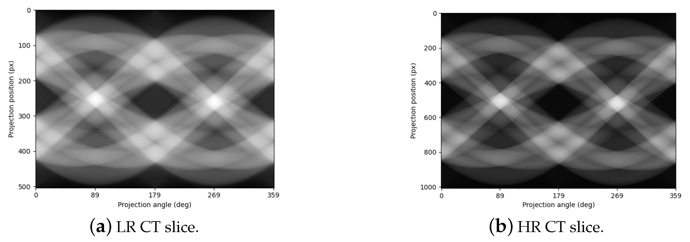
2.1. Image Interpolation Enhancement: Bicubic Interpolation

The bicubic interpolation technique is initially used to optimize and temporarily enlarge the input image’s details in order to mitigate the detail loss brought on by low resolution in the metal lattice structure slices of industrial CT. Sixteen sampling locations close to the input pixels serve as the foundation for this technique. It achieves a smooth transition area of the image while keeping the important edge features by performing weighted interpolation on the target pixel values using the cubic convolution kernel function. This gives the image a richer information base for further processing and transformations. The interpolation function is defined as follows:
f ( x , y ) = i = 1 2 j = 1 2 ω ( i , j ) · I ( x + i , y + j )
where the weight w ( i , j ) is dependent on the distance factor; it can effectively eliminate the sawtooth effect and blurring during image interpolation while satisfying continuity and smoothness. I ( x + i , y + j ) is a neighborhood point in image I relative to the target pixel ( x , y ) . Because biometric interpolation requires the use of × 4 neighborhood pixels (i.e., 16 points), the range of i and j is from −1 to 2, with a total of four values; each I ( x + i , y + j ) is an actual pixel value around the target pixel and is used to participate in the weighted average. In addition to increasing the image’s spatial resolution, bicubic interpolation also improves the feature expression in the projection space and supplies more precise information for the Radon transform that follows.

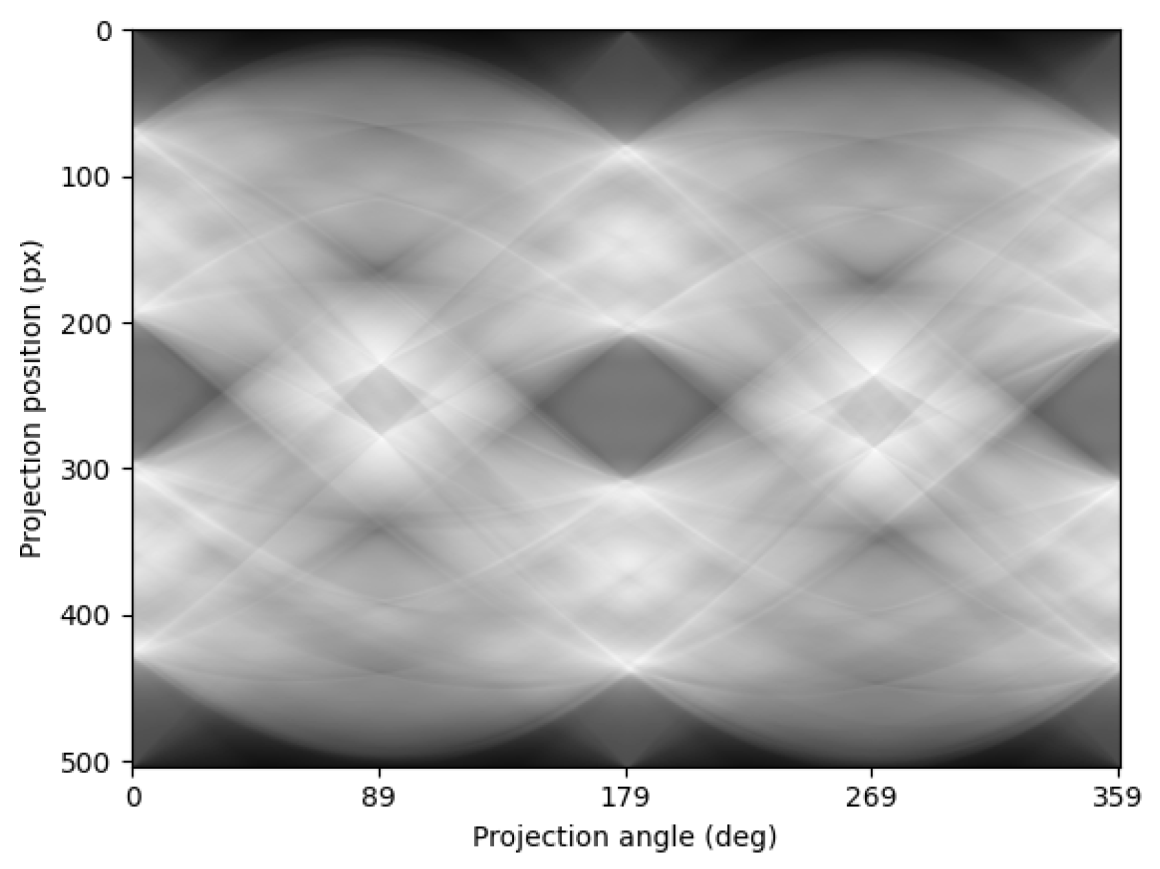
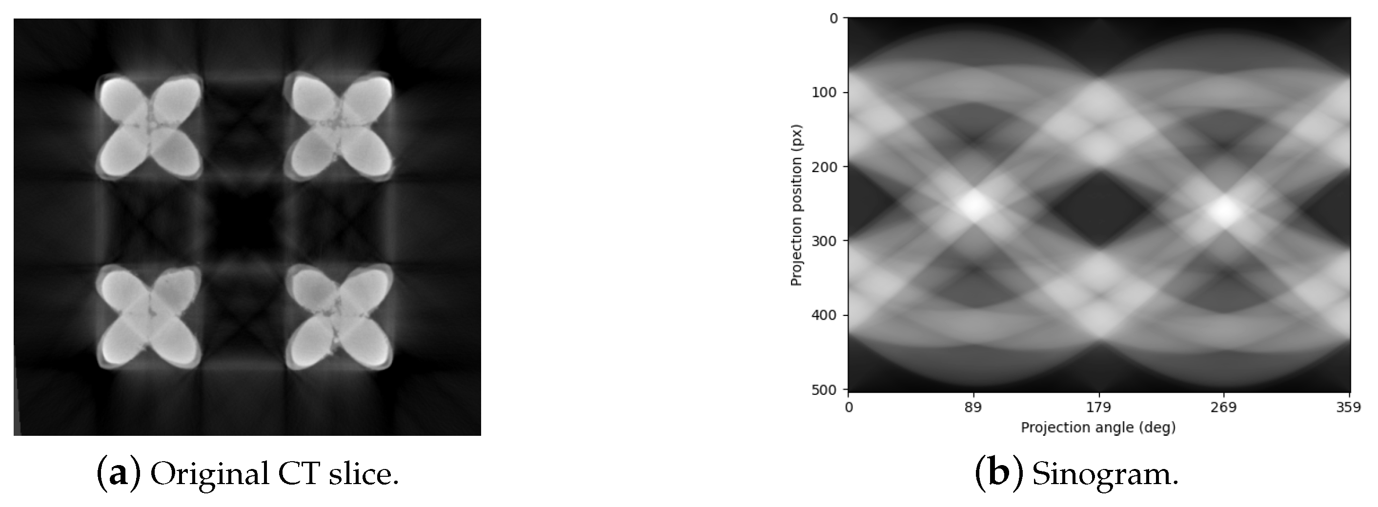
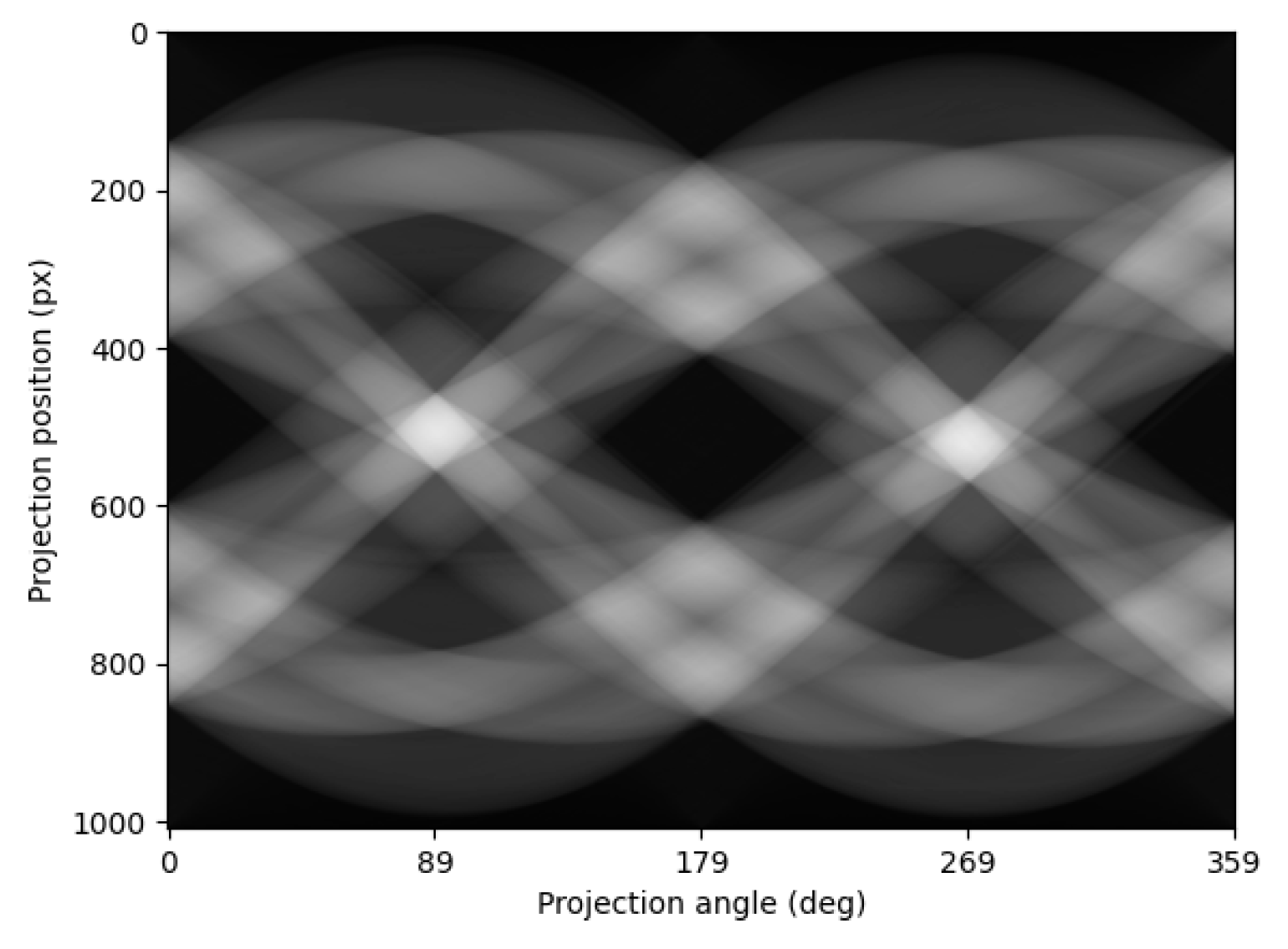
2.2. Radon Transform and Sinogram Generation

The Radon transform reveals the integral projection information of CT images at various angles by converting the spatial domain image into a sinusoidal graph in the projection domain. A crucial input for the ensuing artifact difference processing, the sinogram graphically depicts the artifact features brought on by the metal structure. A two-dimensional spatial image can be transformed into a collection of its projections at various angles using the Radon transform. The following is its formula:
R ( θ , s ) = f ( x , y ) δ ( s x cos θ y sin θ ) d x d y
where s is the projection distance, δ is the Dirac function, f ( x , y ) is the gray value of the input picture, and θ [ 0 , π ) is the projection angle. The basis for processing artifact differences is laid by the sinogram R ( θ , s ) produced by the Radon transform, which can clearly map the characteristic structure related to metal artifacts.

2.3. Differential Removal of Metal Artifacts

The matching artifact sine graph model is built based on the examination of the metal lattice structure’s artifact projection properties. The artifact component is greatly suppressed, its impact on the ensuing network optimization is lessened, and detail compensation space is preserved for super-resolution reconstruction by differentiating the original sine graph with the artifact model. The matching artifact sinogram template R m e t a l ( θ , s ) is established for the metal artifacts unique to the lattice structure. The following formula is used to eliminate the artifacts using a difference operation:
R c l e a n ( θ , s ) = R i n p u t ( θ , s ) R m e t a l ( θ , s )
As shown in Figure 2, the threshold segmentation method is first used to eliminate the metal pixels in the CT slices to generate CT sections that contain only metal artifacts. The sinogram is then produced by applying the Radon transform on the filled image, as seen in Figure 3. To acquire the sinogram after removing the artifacts, which is needed for the future super-resolution reconstruction optimization, we compute the difference between the sinogram with metal artifacts and the sinogram with only metal artifacts.

2.4. Lightweight Super-Resolution Network Optimization Based on Channel Attention Mechanism

The framework’s central part, a lightweight, physically limited super-resolution network with the goal of achieving positive detail compensation and noise suppression following the elimination of sinogram artifacts, is proposed. To improve the responsiveness of important feature channels, we create a thin residual network based on the EDSR design and incorporate the channel attention mechanism. Following artifact difference, this network applies noise suppression and detail correction to the sine graph. It achieves high-quality super-resolution reconstruction of the information in the projection domain when combined with the composite loss function of Radon physical constraint.

2.4.1. Edsr-Tiny Network

The EDSR-Tiny lightweight super-resolution network structure, designed in this paper, is shown in Figure 4. By combining module simplification and the attention mechanism, the entire architecture accomplishes effective and efficient image reconstruction while carrying over the residual learning concept from the old EDSR. Through residual skip connections and sequential connections, the modules are closely coordinated, improving reconstruction accuracy and facilitating an efficient information flow. High-resolution CT sinusoidal graph super-resolution reconstruction jobs can be processed with low computer resources thanks to the network’s general design, which balances performance and a lightweight size.
The high-resolution images:
The process of obtaining high-resolution images is as follows: Firstly, the threshold segmentation method is used to remove the metal pixels in the CT slice to generate a section that only contains metal artifacts. Then, a sinogram is generated by applying the Radon transform on the filled image. Finally, the two sinograms are differentiated. The differentiated graphs are processed as images, and the inverse Radon transform is performed to obtain high-resolution CT sections. The subsequent high-resolution sinogram was also obtained from this.
The key modules of the network structure:
Input layer (Input): This module is in charge of performing the preliminary feature extraction after receiving the preprocessed metal artifact difference sine graph. The original image is converted into a high-dimensional feature space appropriate for deep feature learning by a number of convolution processes.
Convolutional layer (Conv): This component improves the image’s texture and edge information, further extracts the image’s local spatial characteristics, and supplies a rich feature base for the residual block processing that follows.
Residual block: The network’s central component, the residual block, is made up of several convolutional layers and activation functions and is employed for nonlinear mapping and deep feature extraction. The residual structure enhances data transfer efficiency and mitigates the issue of vanishing gradients in deep network training via skip links. In particular, the residual block ensures smooth information flow and nonlinear expression capabilities by containing two ReLU activations and three convolution processes.
Channel attention layer (CALayer): A module for the channel attention mechanism built within the residual block. It increases the sensitivity and recovery capacity of the network for significant picture details by adaptively modifying the feature weights of each channel, which highlights the critical channel information and reduces redundant noise.
Upsample layer: This module recovers the spatial scale of the high-resolution image, gets ready for the final image output, and enlarges the depth feature map to the target resolution using methods like interpolation or transpose convolution.
The formula description of the network structure:
Assume that the input low-resolution sinogram is X and that the network produces a high-resolution reconstruction result of Y ^ = F ( X ; θ ) . The mapping function of the entire super-resolution network is denoted by F, with θ as its parameter.
Initial feature extraction layer: Extract the initial features through convolution operations:
F = C o n v ( X )
Representation of residual blocks: There is a single residual block in the network. The convolution and ReLU activation layers are used to nonlinearly map the features within each residual block, and a channel attention mechanism (CALayer) is introduced to modify the channel weights. The i-th residual block’s input–output relationship can be written as follows:
F i = R e s i d u a l B l o c k ( F i 1 ) = F i 1 A ( σ ( C o n v ( F i 1 ) ) )
where σ represents the ReLU activation function and A represents the channel attention layer.
Feature fusion and upsampling: After the residual block outputs are fused, upsampling is performed to restore the high-resolution spatial size:
F u p = U p s a m p l e ( F N )
Final output: The network output after the last layer of convolution is generated:
Y ^ = C o n v ( F u p ) + X i n t e r p
where X is the baseline for the residual connection and is the input image enlarged by bicubic interpolation.

2.4.2. Channel Attention Layer (CALayer)

The channel attention mechanism is introduced to improve the network’s capacity to recognize the features of important channels. This approach improves the relevance and efficacy of detail restoration by assisting the network in concentrating on the important information channels associated with artifacts.
In the residual module, the channel attention mechanism extracts the global responses of each channel in the feature map through the global average pooling operation and then learns a set of normalized channel weights through a two-layer fully connected network. These weights reflect the ability of different channels to express the periodic information of the lattice structure. The attention mechanism enables the network to dynamically enhance the focus on key feature channels such as periodic stripes and structural intersection areas and suppress the response to fuzzy areas or redundant background information.
In the sinogram of the lattice structure, the low-frequency channels often carry periodic skeleton information, while the high-frequency channels are more sensitive to boundary details and texture disturbances. The channel attention mechanism can adaptively assign weights according to the image content to enhance the expressive ability of effective features. Ultimately, the reconstruction results enhance the edge contour and local details while maintaining the integrity of the global periodic structure, achieving high-quality super-resolution reconstruction of the lattice structure sinogram. The following are the precise stages involved in implementation.
Feature pooling: We enter the feature map F R C × H × W . Global maximum pooling (GMP) and global average pooling (GAP) will yield two channel descriptors, respectively:
f a v g = G A P ( F ) = 1 H × W i = 1 H j = 1 W F c , i , j
f m a x = G M P ( F ) = max i , j F c , i , j
where, c = 1 , 2 , , C represents the channel index.
Shared multi-layer perceptron (MLP) transformation: Two descriptors, respectively, travel through MLP with shared parameters. MLP consists of two fully connected layers, and the number of nodes in the hidden layer is C r , where r is the reduction rate, generally given as 16:
M L P ( f ) = W 2 · R e L U ( W 1 · f )
Co-fusion weight calculation: To create the final channel weights, we combine the two outputs and turn them on using Sigmoid:
M ( c ) = σ ( M P L ( f a v g ) + M P L ( f m a x )
Channel recalibration: To perform channel weighting, we multiply the weight M c back to the original feature map:
F = M ( c ) F

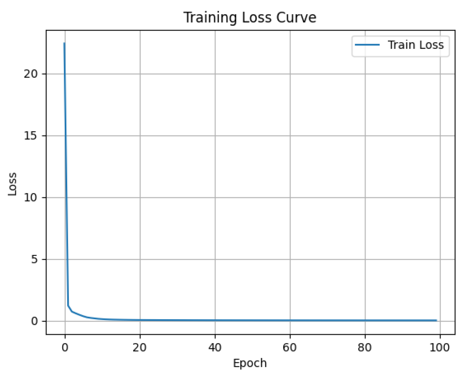
2.4.3. Loss Function

By using this composite loss function, the network effectively suppresses the artifact of the metal lattice structure and restores high-quality CT images by improving the image’s detail representation in the spatial domain while also accounting for the consistency of physical information in the Radon projection domain. The reconstruction error in the spatial domain and the physical consistency error in the Radon projection domain make up the two components of the composite loss function established in this research, which efficiently combines the physical limitations of the Radon transform.
L = λ 1 L p i x e l + λ 2 L R a d o n
where λ 1 and λ 2 are weight coefficients, which are used to balance the reconstruction error in the spatial domain and the consistency error in the projection domain. L p i x e l is the pixel reconstruction loss, and L R a d o n is the physical consistency loss in the Radon domain.
Pixel reconstruction loss (Pixel Loss) uses mean square error (MSE) to quantify the difference between the high-resolution real picture Y and the network output image Y ^ :
L p i x e l = 1 N i = 1 N Y ^ i Y i 2 2
In order to guarantee that the network’s output image in the Radon transform domain is consistent with the projection of the actual image, as well as to encourage artifact suppression and structure restoration, the physical consistency loss in the Radon domain (Radon Loss) is utilized:
L R a d o n = 1 N i = 1 N R ( Y ^ i ) R ( Y i ) 2 2
where R ( ) represents the Radon transformation operation and N is the number of training samples.
During the training process of the network, while the network calculates the pixel-level loss of the sinogram, it also calculates the loss of CT slices obtained by the inverse Radon transform. This both ensures pixel-level features and takes into account the physical consistency of the Radon domain.

2.5. Inverse Radon Transformation and Reconstruction

To reconstruct the spatial-domain CT section image with rich information and no artifacts, the filtered back-projection approach optimizes the sinogram, which is then subjected to the inverse Radon transform. Projecting the projection value P ^ ( θ , s ) at each angle θ in the opposite direction along the corresponding ray direction into the two-dimensional image space is the fundamental concept of the inverse Radon transform. And we use multi-angle superposition to obtain the image f ^ ( x , y ) . The following is its formula:
f ^ ( x , y ) = 0 π P ^ ( θ , x cos θ y sin θ ) d θ
where θ is the coordinate of the matching picture and θ is the projection angle. The projected values in all directions along their corresponding directions are accumulated in reverse during the integration process.

2.6. Evaluation Metrics

In this paper, two evaluation metrics were used to verify the effectiveness of the proposed method. The peak signal-to-noise ratio (PSNR) measures the ratio between the maximum possible power of a signal and the power of corrupting noise. The signal-to-noise ratio (SNR) evaluates the level of desired signal to background noise, providing an indication of structural clarity.

3. The Experimental Results

Experiments were carried out in this part to verify the efficacy of the suggested approach. First, the relevant characteristics and the sources of the CT sections used in this work are presented. Next, the EDSR-Tiny network’s training set is described, consisting of low-resolution CT slices and high-resolution CT slices with artifacts eliminated. The training outcomes of EDSR-Tiny are then displayed. By comparing the PSNR and SNR of CT sections before and after reconstruction, the method’s viability is finally confirmed.

3.1. Dataset Preparation

A titanium alloy lattice structure sample measuring 5 cm by 5 cm by 10 cm is employed as the research item in this paper. Figure 5 depicts the test piece.
In this paper, the model of the equipment is IPT04203C produced by GRANPECT. This device has two radiation sources (450 kV and 160 kV), with Comet Company (Flamatt, Switzerland) producing the 450 kV radiation source and WorX Company (Suzhou, China) producing the 160 kV radiation source. An industrial micro-focus CT with a voltage of 160 kV was used. 145 kV was the scanning voltage, 220 μ A was the current, and 1000 ms was the exposure time, A total of 1440 frames were scanned in 360 degrees, 2048 × 2048 was the reconstruction matrix, 0.07 mm was the pixel size, and 0.1 mm was the reconstruction height.The detailed parameters are shown in Table 1. Figure 6 displays the equipment diagram.
The original CT section is shown in Figure 7. It can be seen from Figure 7 that there are many metal artifacts in the lattice structure CT slices at different stages.
As mentioned earlier, the datasets used for training are all sinograms obtained by Radon transformation. The training set consists of 130 sinograms of high-resolution transformations and 130 sinograms of high-resolution downsampling transformations. The learning of high/low-resolution images yields the final EDSR-Tiny network. Considering the periodic variation of the lattice structure, the super-resolution network uses 30 slices as the validation set and 100 carefully selected slices as the training set. High-resolution images are obtained after processing, while low-resolution images are obtained through high-resolution downsampling. Figure 8 shows the dataset.

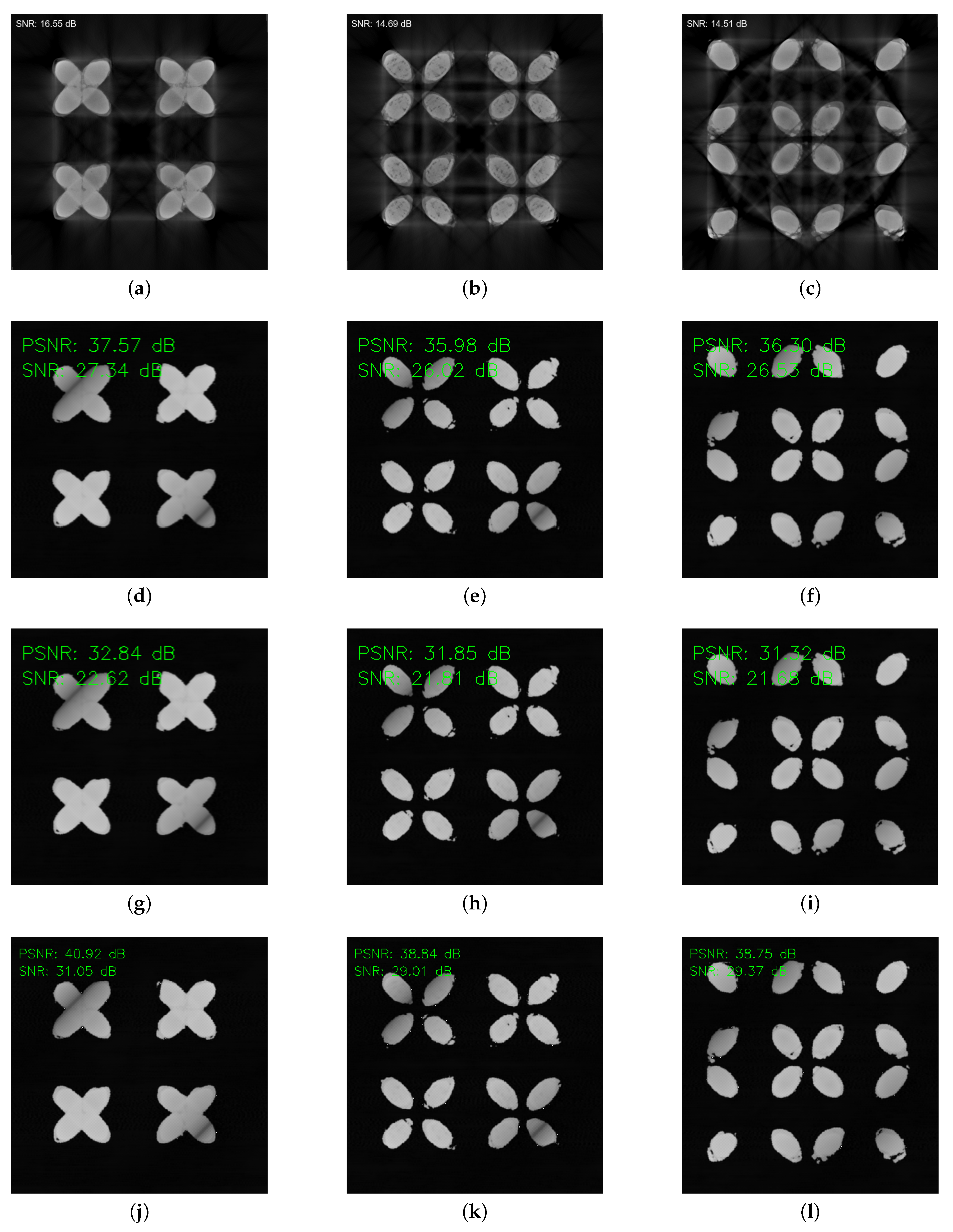
3.2. The Result of Removing Metal Artifacts

The CT slices need to undergo Radon transformation. Figure 9a shows the original CT slice after scanning, and it can be seen that there are very heavy metal artifacts. Figure 9b shows the sinogram of the original CT section after the Radon transformation.
A single NVIDIA GeForce RTX 3090 (24 GB) GPU and a 13th Gen Intel Core i9-13900K were used to train all models. With a total epoch of 100 and default approaches for other parameters, the training was based on the deep learning framework PyTorch 2.0.1. Figure 10 shows the result after the training of EDSR-Tiny. The model tends to stabilize after 40 epochs.
After removing the metal artifacts, the sinogram was reconstructed using the learned model. The reconstructed sinogram is displayed in Figure 11. The reconstructed sinogram is more lucid than the original sinogram (Figure 9b). The PSNR and SNR were computed using the inverse Radon transform.
Table 2 shows that the original image’s average signal-to-noise ratio (SNR) was 14.27 dB. Following optimization, the SNR result was 29.75 dB, with a one-time improvement in signal quality. The reconstructed slice has a PSNR of 40.39 dB, making it a high-quality image. Additionally, Table 2 shows the SNR, PSNR, and PSNR’s variance values of the inverse Radon transform following the removal of metal artifacts from the sinogram using bicubic interpolation. The CT slice that was reconstructed using biometric interpolation had an SNR of 20.13 dB and a PSNR of 30.25 dB, according to the data. The results of CycleGAN and bicubic interpolation are not significantly different. The pix2pix network has seen significant improvement, and the optimization results of pix2pix are the most stable, but the PSNR still falls short of the method proposed in this paper. Figure 12 shows the PSNR distribution of the pix2pix, CycleGAN, and EDSR-Tiny test sets. The results of EDSR-Tiny are almost always superior to the other two methods, which is consistent with the conclusion in Table 2. A visual comparison chart between the original and reconstructed images can be found in Figure 13.
An ablation study was suggested in order to demonstrate the efficacy of the EDSR-Tiny improvement, and Table 3 displays the findings. Table 3 shows that the following are the outcomes of the reconstruction utilizing the original EDSR-Tiny: 22.13 dB is the average SNR, and 33.25 dB is the average PSNR. The CALayer was used to boost the average SNR of the reconstruction findings by 3.15 dB and the average PSNR by 2.12 dB. The results show that the CALayer was a successful introduction. The Radon loss was used to boost the average SNR of the reconstruction findings by 3.45 dB and the average PSNR by 3.56 dB. It was demonstrated that introducing the Radon loss is effective.
To avoid generality, a structural component made of 316L stainless steel with a rhombic structure was added, as shown in Figure 14. The CT optimization results are shown in Figure 15. It can be clearly seen that after the optimization by the method in this paper, the metal artifacts in the CT sections are significantly reduced. The validity and generalization of this method are further proved.

4. Discussion and Conclusions

This study introduces a new technique to boost the quality of industrial CT image reconstruction by combining lightweight attention-enhanced super-resolution networks with Radon-domain artifact suppression. Results from experiments show that the suggested method significantly improves PSNR and SNR metrics while preserving important structural details and successfully reducing metal artifacts, particularly in high-density areas.
Radon-domain processing, in contrast to traditional image-domain correction methods, makes use of the fundamental physics of artifact creation to produce more focused and efficient suppression. The structure of the super-resolution module is simple, consisting of a single residual block enhanced by a channel attention mechanism. Because of its low computing complexity and improved feature representation, this architecture makes the approach ideal for use in industrial settings with limited resources.
Nevertheless, there are certain drawbacks to the existing approach. Slice-wise 2D processing may introduce inter-slice inaccuracy in volumetric reconstructions, and it may have trouble generalizing when faced with extremely varied or irregular artifact patterns. Future research will concentrate on expanding the architecture to three-dimensional networks for better volumetric consistency and implementing adaptive artifact modeling techniques in the Radon domain in order to overcome these problems. Furthermore, using spectral CT data will facilitate material fusion and decomposition, improving the model’s performance on intricate, multi-material components.
In summary, the suggested method shows scalability and practical efficacy in eliminating metal artifacts from industrial CT images while maintaining structural integrity. The technique opens the door for wider uses in nondestructive testing and digital inspection of intricately engineered parts by offering a viable approach for high-quality and deployable CT reconstruction.

Author Contributions

Conceptualization, H.L.; methodology, B.W.; software, Z.Z.; writing—original draft preparation, B.W.; writing—review and editing, Z.Z.; visualization, R.W.; funding acquisition, Z.Z. All authors have read and agreed to the published version of the manuscript.

Funding

The authors gratefully thank the Science & Technology Program of Hebei [No. 246Z1002G] for its support.

Institutional Review Board Statement

Not applicable.

Informed Consent Statement

Not applicable.

Data Availability Statement

The data presented in this study are available on request from the corresponding author. And the data are not publicly available due to privacy.

Acknowledgments

We gratefully thank each of the authors of the references and acknowledge the use Quillbot software v4.4.15 to check for grammar errors.

Conflicts of Interest

The authors declare no conflicts of interest.

References

  1. Boas, F.E.; Fleischmann, D. CT artifacts: Causes and reduction techniques. Imaging Med. 2012, 4, 229–240. [Google Scholar] [CrossRef]
  2. Wellenberg, R.; Hakvoort, E.; Slump, C.; Boomsma, M.; Maas, M.; Streekstra, G. Metal artifact reduction techniques in musculoskeletal CT-imaging. Eur. J. Radiol. 2018, 107, 60–69. [Google Scholar] [CrossRef]
  3. Gjesteby, L.; De Man, B.; Jin, Y.; Paganetti, H.; Verburg, J.; Giantsoudi, D.; Wang, G. Metal artifact reduction in CT: Where are we after four decades? IEEE Access 2016, 4, 5826–5849. [Google Scholar] [CrossRef]
  4. Selles, M.; van Osch, J.A.; Maas, M.; Boomsma, M.F.; Wellenberg, R.H. Advances in metal artifact reduction in CT images: A review of traditional and novel metal artifact reduction techniques. Eur. J. Radiol. 2024, 170, 111276. [Google Scholar] [CrossRef]
  5. Kalender, W.A.; Hebel, R.; Ebersberger, J. Reduction of CT artifacts caused by metallic implants. Radiology 1987, 164, 576–577. [Google Scholar] [CrossRef]
  6. Meyer, E.; Raupach, R.; Lell, M.; Schmidt, B.; Kachelrieß, M. Normalized metal artifact reduction (NMAR) in computed tomography. Med. Phys. 2010, 37, 5482–5493. [Google Scholar] [CrossRef]
  7. Meyer, E.; Raupach, R.; Lell, M.; Schmidt, B.; Kachelrieß, M. Frequency split metal artifact reduction (FSMAR) in computed tomography. Med. Phys. 2012, 39, 1904–1916. [Google Scholar] [CrossRef]
  8. Scardigno, R.M.; Brunetti, A.; Marvulli, P.M.; Carli, R.; Dotoli, M.; Bevilacqua, V.; Buongiorno, D. CALIMAR-GAN: An unpaired mask-guided attention network for metal artifact reduction in CT scans. Comput. Med. Imaging Graph. 2025, 123, 102565. [Google Scholar] [CrossRef]
  9. Yu, L.; Zhang, Z.; Li, X.; Ren, H.; Zhao, W.; Xing, L. Metal artifact reduction in 2D CT images with self-supervised cross-domain learning. Phys. Med. Biol. 2021, 66, 175003. [Google Scholar] [CrossRef]
  10. Zhu, L.; Han, Y.; Xi, X.; Li, L.; Yan, B. Completion of metal-damaged traces based on deep learning in sinogram domain for metal artifacts reduction in CT images. Sensors 2021, 21, 8164. [Google Scholar] [CrossRef]
  11. Peng, C.; Li, B.; Li, M.; Wang, H.; Zhao, Z.; Qiu, B.; Chen, D.Z. An irregular metal trace inpainting network for x-ray CT metal artifact reduction. Med. Phys. 2020, 47, 4087–4100. [Google Scholar] [CrossRef]
  12. Xu, L.; Zeng, X.; Li, W.; Zheng, B. MFGAN: Multi-modal feature-fusion for CT metal artifact reduction using GANs. ACM Trans. Multimed. Comput. Commun. Appl. 2023, 19, 1–17. [Google Scholar] [CrossRef]
  13. Wang, H.; Li, Y.; He, N.; Ma, K.; Meng, D.; Zheng, Y. DICDNet: Deep interpretable convolutional dictionary network for metal artifact reduction in CT images. IEEE Trans. Med. Imaging 2021, 41, 869–880. [Google Scholar] [CrossRef]
  14. Shi, Z.; Wang, N.; Kong, F.; Cao, H.; Cao, Q. A semi-supervised learning method of latent features based on convolutional neural networks for CT metal artifact reduction. Med. Phys. 2022, 49, 3845–3859. [Google Scholar] [CrossRef]
  15. Kim, S.; Ahn, J.; Kim, B.; Kim, C.; Baek, J. Convolutional neural network–based metal and streak artifacts reduction in dental CT images with sparse-view sampling scheme. Med. Phys. 2022, 49, 6253–6277. [Google Scholar] [CrossRef]
  16. Ikuta, M.; Zhang, J. A deep recurrent neural network with FISTA optimization for CT metal artifact reduction. IEEE Trans. Comput. Imaging 2022, 8, 961–971. [Google Scholar] [CrossRef]
  17. Nakao, M.; Imanishi, K.; Ueda, N.; Imai, Y.; Kirita, T.; Matsuda, T. Regularized three-dimensional generative adversarial nets for unsupervised metal artifact reduction in head and neck CT images. IEEE Access 2020, 8, 109453–109465. [Google Scholar] [CrossRef]
  18. Koike, Y.; Anetai, Y.; Takegawa, H.; Ohira, S.; Nakamura, S.; Tanigawa, N. Deep learning-based metal artifact reduction using cycle-consistent adversarial network for intensity-modulated head and neck radiation therapy treatment planning. Phys. Med. 2020, 78, 8–14. [Google Scholar] [CrossRef]
  19. Liao, H.; Lin, W.A.; Zhou, S.K.; Luo, J. ADN: Artifact disentanglement network for unsupervised metal artifact reduction. IEEE Trans. Med Imaging 2019, 39, 634–643. [Google Scholar] [CrossRef]
  20. Ketcha, M.D.; Marrama, M.; Souza, A.; Uneri, A.; Wu, P.; Zhang, X.; Helm, P.A.; Siewerdsen, J.H. Sinogram+ image domain neural network approach for metal artifact reduction in low-dose cone-beam computed tomography. J. Med Imaging 2021, 8, 052103. [Google Scholar] [CrossRef]
  21. Lee, D.; Park, C.; Lim, Y.; Cho, H. A metal artifact reduction method using a fully convolutional network in the sinogram and image domains for dental computed tomography. J. Digit. Imaging 2020, 33, 538–546. [Google Scholar] [CrossRef]
  22. Yu, L.; Zhang, Z.; Li, X.; Xing, L. Deep sinogram completion with image prior for metal artifact reduction in CT images. IEEE Trans. Med. Imaging 2020, 40, 228–238. [Google Scholar] [CrossRef]
  23. Wang, T.; Xia, W.; Huang, Y.; Sun, H.; Liu, Y.; Chen, H.; Zhou, J.; Zhang, Y. DAN-Net: Dual-domain adaptive-scaling non-local network for CT metal artifact reduction. Phys. Med. Biol. 2021, 66, 155009. [Google Scholar] [CrossRef]
Figure 1. The diagram of framework.
Applsci 15 07819 g001
Figure 2. The CT slice of metal artifacts.
Applsci 15 07819 g002
Figure 3. The sinogram of metal artifacts.
Applsci 15 07819 g003
Figure 4. EDSR-Tiny network. Including the entire framework of the network and the network structure of key modules.
Applsci 15 07819 g004
Figure 5. Lattice structure sample.
Applsci 15 07819 g005
Figure 6. Industrial micro-focus CT with a voltage of 160 kV.
Applsci 15 07819 g006
Figure 7. CT slices. They are each CT slices of distinct layers inside the same structure. The image shows that metal artifacts are present in CT sections of several levels, and they all have distinct shapes.
Applsci 15 07819 g007
Figure 8. Training dataset of EDSR-Tiny. The training set consists of high-resolution sinograms and low-resolution images sampled under the high-resolution sinograms. The contrast of the high-resolution sinogram is clear, while that of the low-resolution sinogram is generally brighter.
Applsci 15 07819 g008
Figure 9. The results of Radon transformation. (a) shows the original CT section containing metal artifacts, and (b) shows the sinogram obtained by its Radon transform.
Applsci 15 07819 g009
Figure 10. Training results. It can be seen that the model converges rapidly and tends to be stable after 40 epochs of training.
Applsci 15 07819 g010
Figure 11. The sinogram reconstructed by EDSR-Tiny.
Applsci 15 07819 g011
Figure 12. The PSNR results of the test set. The CT slices obtained by the EDSR-Tiny method are almost always superior to the other two methods.
Applsci 15 07819 g012
Figure 13. Optimization comparison results of metal artifacts. The results of Radon transformation. The results show that the method proposed in this paper is better than pix2pix and CycleGAN networks at removing metal artifacts. (a) Original CT slice 1. (b) Original CT slice 2. (c) Original CT slice 3. (d) CT slice 1 after removing artifacts by pix2pix. (e) CT slice 2 after removing artifacts by pix2pix. (f) CT slice 3 after removing artifacts by pix2pix. (g) CT slice 1 after removing artifacts by CycleGAN. (h) CT slice 2 after removing artifacts by CycleGAN. (i) CT slice 3 after removing artifacts by CycleGAN. (j) CT slice 1 after removing artifacts by EDSR-Tiny. (k) CT slice 2 after removing artifacts by EDSR-Tiny. (l) CT slice 3 after removing artifacts by EDSR-Tiny.
Applsci 15 07819 g013
Figure 14. Diamond lattice structural components made of stainless steel 316L material.
Applsci 15 07819 g014
Figure 15. The optimization result of the diamond lattice structure artifact reduction for stainless steel 316L. It can be seen from this that the method proposed in this paper can effectively remove metal artifacts. (a) Original CT slice 1. (b) Original CT slice 2. (c) CT slice 1 after removing artifacts. (d) CT slice 2 after removing artifacts.
Applsci 15 07819 g015
Table 1. Scanning parameters.
Voltage145 kVCurrent220 μA
Exposure time1000 msFrames1440
Reconstruction matrix2048 × 2048pixel size0.07 mm × 0.07 mm × 0.1 mm
Table 2. The comparison results before and after reconstruction.
MethodAverage SNRAverage PSNRThe Variance of PSNR
Original14.27 dB--
Bicubic interpolation method20.13 dB30.25 dB-
CycleGAN21.63 dB32.53 dB2.21 dB
pix2pix26.26 dB37.13 dB0.82 dB
Reconstruction using EDSR-Tiny29.75 dB 40.39 dB 2.56 dB
Table 3. Ablation studies.
L Radon Without L Radon CALayerWithout CALayerSNRPSNR
22.13 dB33.25 dB
+3.15 dB+2.12 dB
+3.45 dB+3.56 dB
+7.62 dB+7.14 dB
Disclaimer/Publisher’s Note: The statements, opinions and data contained in all publications are solely those of the individual author(s) and contributor(s) and not of MDPI and/or the editor(s). MDPI and/or the editor(s) disclaim responsibility for any injury to people or property resulting from any ideas, methods, instructions or products referred to in the content.

