Article

A Novel Hierarchical Multi-Stable Cylindrical Structure with Superior Energy Trapping

1
College of Mechanical and Electrical Engineering, Qingdao University, Qingdao 266071, China
2
Institut FEMTO-ST, CNRS, Universite Marie et Louis Pasteur, 25000 Besançon, France
3
National Key Laboratory of Science and Technology on Advanced Composites in Special Environments, Harbin Institute of Technology, Harbin 150001, China
*
Authors to whom correspondence should be addressed.
Appl. Sci. 2025, 15(14), 7748; https://doi.org/10.3390/app15147748
Submission received: 20 May 2025 / Revised: 19 June 2025 / Accepted: 8 July 2025 / Published: 10 July 2025

Abstract

Multi-stable mechanical metamaterials based on the snap-through behavior of cosine beams have been shown to have significant potential in the field of capacity absorption due to their advantages such as reusability and structural simplicity. However, traditional multi-stable metamaterials have exhibited limitations in both energy absorption and trapping ability. Inspired by the bionic multilevel structure, a novel hierarchical multi-stable cylindrical structure (HMCS) based on cosine curved beams is proposed. We investigated the snap-through behaviors and energy absorption capacity of the HMCS. Both finite element simulation results and experimental results show that the hierarchical multi-stable structure exhibits excellent specific energy absorption and energy trapping capabilities compared to traditional multi-stable cylindrical structures (TMCSs). Furthermore, by analyzing the effect of height h and thickness t on the snap-through behavior of the structure, the key parameters determining the mono-stable or bi-stable response are identified. In addition, a gradient-based study of the structure reveals the dominant role of stiffness in the snap-through behavior of multilayer structures. This work provides insights into the application of multi-stable cylindrical structures in energy trapping and absorption and offers a new strategy for designing high-efficiency energy-absorbing metamaterials.

1. Introduction

Mechanical metamaterials [1,2] are composed of periodically arranged building blocks and carefully designed unit cells, whose properties primarily derive from structural geometry rather than the inherent composition of the base materials [3,4]. This characteristic enables them to achieve functionalities beyond the reach of traditional materials, including negative stiffness [5,6], a negative Poisson’s ratio [7,8], negative thermal expansion [9], and programmability [10,11]. As an important branch of mechanical metamaterials, multi-stable metamaterials have gained widespread attention for their superior performance in energy trapping [12,13,14], vibration control [15], wave manipulation [16], and smart deformable structure [17,18].
Multi-stable metamaterials typically originate from the arrangement and configuration of specific units, such as bi-stable beams [19,20], origami structures [21,22,23,24], composite laminates [25,26], or flexible units [27,28]. Among these, bi-stable curved beams exhibiting elastic instability are the most typical negative stiffness unit, rapidly switching between two stable states under external loading, thereby enabling energy absorption and release [29]. Based on load–displacement curves, curved beams can be classified into two types: multi-stable and mono-stable [30,31]. Bi-stable curved beams maintain their deformed shapes at a local minimum of elastic energy, requiring no external energy input, whereas mono-stable curved beams spontaneously revert to their original configuration once external loading is removed. By adjusting geometric parameters (e.g., thickness, span, and amplitude) [32,33,34], researchers can effectively regulate the buckling behavior and mechanical response of these beams, providing extensive possibilities for constructing multi-stable structures.
In recent years, numerous studies have conducted in-depth analyses and experiments on the mechanical properties of one-dimensional, two-dimensional, and three-dimensional bi-stable units from various perspectives, including mechanical response [35], thermal behavior [36], dynamic behavior [37], magnetic multi-stable metamaterials [38], and deformation applications [39]. These investigations reveal that geometric modifications [40], Young’s modulus variations [41], temperature dependencies [42], and fiber reinforcement [43] can significantly influence the mechanical properties of planar bi-stable structures. Owing to their unique nonlinear characteristics and high-efficiency energy trapping capabilities, multi-stable structures find broad applications in aerospace [44] and automotive safety and protective systems [45,46]. For instance, they can serve as deployable systems and high-energy-trapping components in aerospace [47] and as efficient cushioning and collision protection devices in automotive applications [48]. Despite recent advances in multi-stable design, traditional multi-stable cylindrical structures (TMCSs) based on curved beam configurations still exhibit critical limitations that hinder their broader application in engineering contexts. Firstly, many TMCS designs are planar or unidirectional in deformation [49,50], restricting their suitability for complex, spatially reconfigurable systems. Secondly, the energy trapping capacity is often constrained by single-layer bi-stable configurations, leading to insufficient energy dissipation under high impact conditions [51]. Additionally, their snap-through responses are typically fixed and untunable, and the lack of structural hierarchy reduces adaptability and system-level integration. Moreover, purely elastic deformation mechanisms in traditional TMCSs often result in limited energy absorption per unit mass, especially at elevated strain rates [52,53]. The present study proposes a hierarchical multi-stable cylindrical structure (HMCS). This novel design aims to simultaneously improve load-bearing capacity, energy trapping performance, and configurational tunability. The outline of this paper is as follows: Firstly, a novel hierarchical multi-stable cylindrical structure (HMCS) based on cosine curved beams is designed. The designed new structure consists of two traditional multi-stable cylindrical structures (TMCSs) combined by nesting. Secondly, the effects of the snap-through behavior and geometrical parameters of the HMCS structure on the energy trapping properties and bi-stable properties are investigated. Then, a multi-stable metamaterial with a tailorable snap-through sequence is obtained by adjusting the thickness of the cosine beam. Finally, conclusions are given.

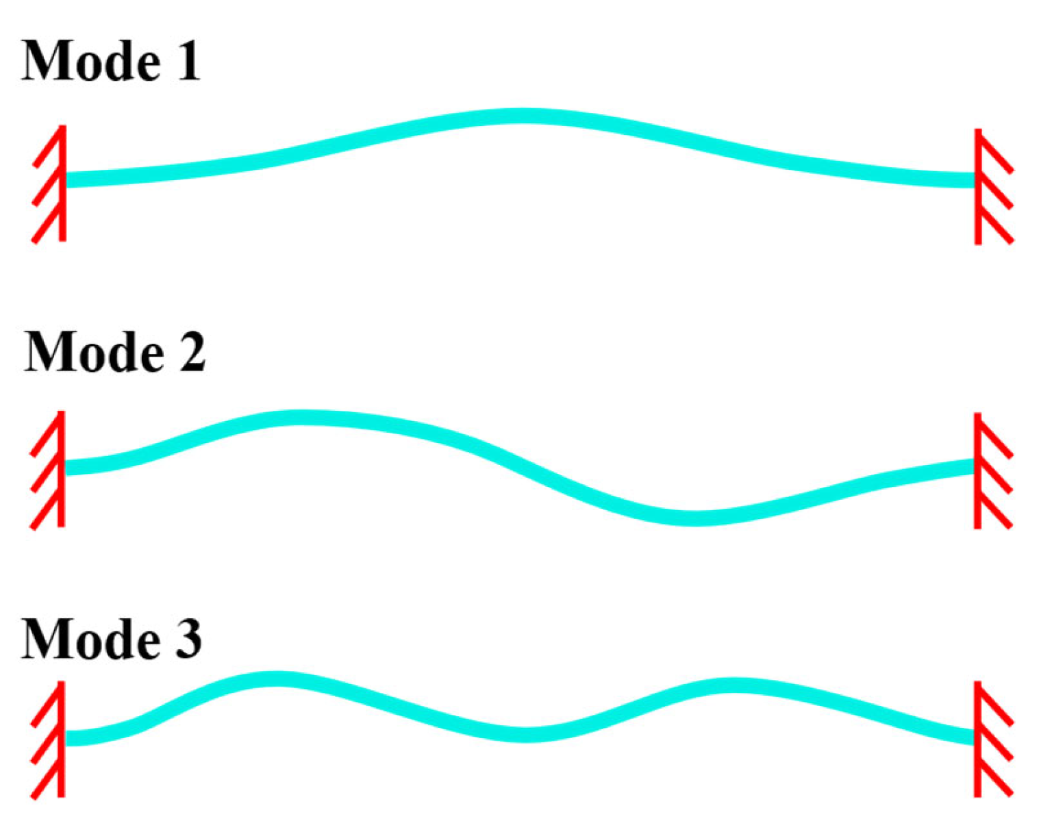
2. Structural Design

2.1. Design of the Bi-Stable Unit Cell

When a straight beam is subjected to axial compression, the structure undergoes a sudden transition from one stable state to another upon reaching the critical load. Therefore, establishing the buckling deformation mechanism of the curved beam model is of great importance. As illustrated in Figure 1, three typical buckling modes of a clamped beam can be observed.
When both ends of the beam segment are constrained, the vertical displacement at the center of the curved beam is governed by the transverse force applied at its midpoint. According to the literature [32], the solutions corresponding to the three buckling modes are given as follows:
F 1 = 3 π 4 Q 2 2 Δ Δ 3 2 + 1 4 4 3 Q 2 Δ 3 2 1 4 4 3 Q 2
F 2 = N 2 N 2 2 N 1 2 8 N 2 2 N 2 2 N 1 2 Δ = 4.18 π 4 2.18 π 4 Δ
F 3 = N 1 2 N 3 2 N 1 2 8 N 3 2 N 3 2 N 1 2 Δ = 8 π 4 6 π 4 Δ
In the expressions, Fi and Δ denote the force and displacement variables, respectively. The geometric parameter Q = h/t, where h and t are the height and thickness of the first buckling mode.
As shown in Figure 2, the mechanical response curve F1 exhibits a cosinusoidal pattern. Its peak value varies with the geometric parameter Q, indicating that the structure possesses nonlinear and variable stiffness characteristics. The slope of the curve undergoes a “positive-negative-positive” transition, which further confirms the presence of a stiffness variation pattern following the same trend. For Q > 2.31 (e.g., Q = 3), the force curve shows negative values, indicating that the structure exhibits bi-stable behavior. In this case, the structure cannot spontaneously return to its original state after unloading and must be restored by applying a reverse external force. When Q = 2.31, the structure reaches a critically bi-stable condition, where the slope balances between positive and negative. In contrast, for Q < 2.31 (e.g., Q = 1.67), the structure exhibits mono-stable behavior and is capable of automatically returning to its original configuration upon the removal of external force.
F3 is tangent to the critical bi-stable curve F1 (Q = 2.31) at Δ = 1, intersects the bi-stable curve F1 (Q = 3) at three distinct points, and intersects the mono-stable curve F1 (Q = 1.67) only at Δ = 1. Under this condition, the second-order asymmetric mode is effectively suppressed, resulting in a pronounced bi-stable effect. Inspired by previous studies [54,55,56,57], an additional beam is incorporated at the midpoint of the cosinusoidal curved beam, as illustrated in Figure 3a. By applying a vertical load at the center of the beam, the structure transitions between two stable configurations. This geometric constraint transforms the second-order bending mode of the curved beam into axial deformation. The design not only prevents the occurrence of asymmetric torsional modes but also maintains geometric symmetry during loading, thereby improving the mechanical stability of the structure.
The predefined shape function of the cosinusoidal curved beam can be expressed as
ω x = h 2 1 cos 2 π x l
The geometric parameters are defined as follows: l is the span of the curved beam, and h is the height of the cosinusoidal curved beam as shown in Figure 3b. t is the thickness of the beam. The width of the curved beam is denoted by b. The proposed cell consists of a cosinusoidal curved beam and several straight supporting beams, as shown in Figure 3c, and is used to design the multi-stable structure.

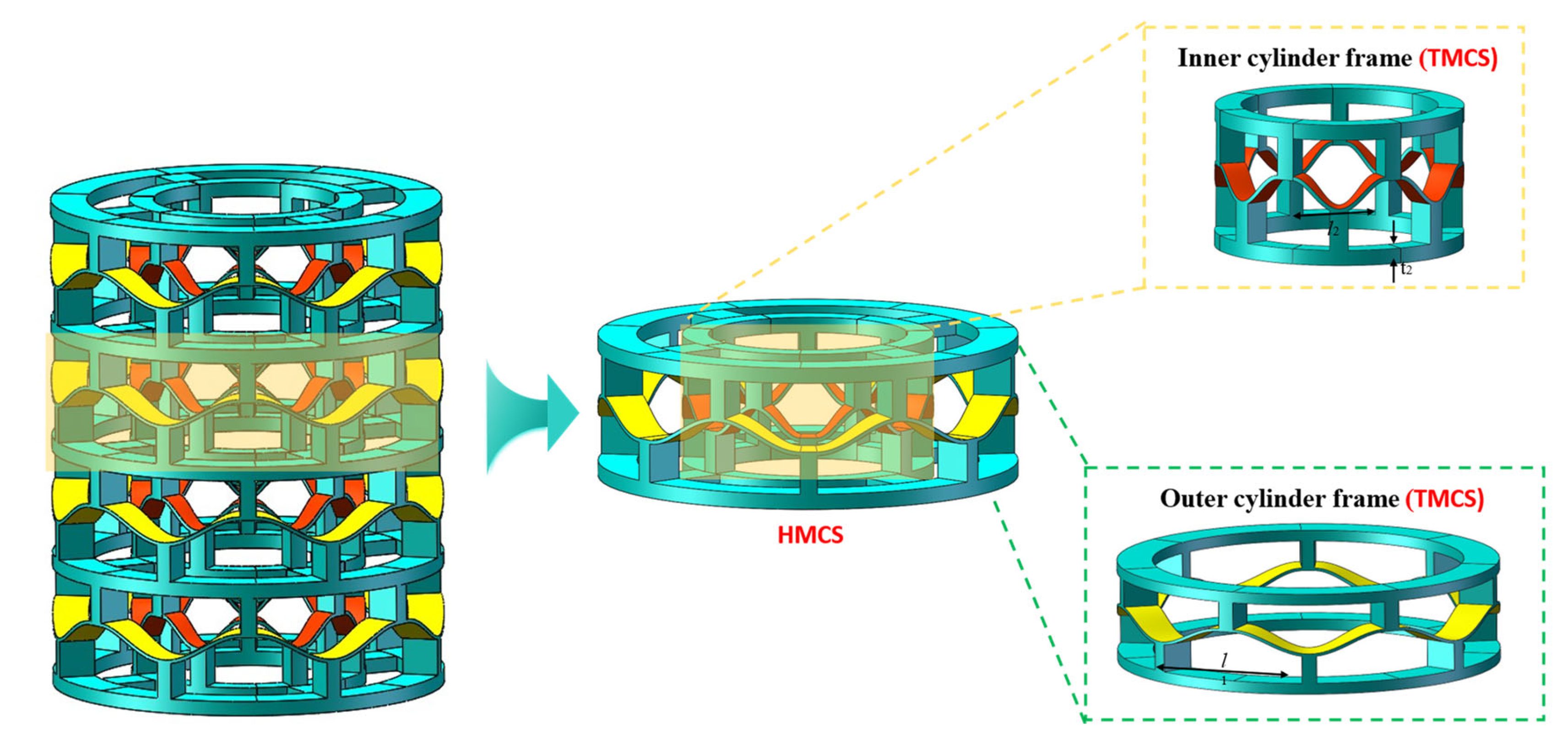
2.2. Design of Hierarchical Multi-Stable Cylindrical Structure (HMCS)

Inspired by the bionic multilevel structure, a novel hierarchical multi-stable cylindrical structure (HMCS) based on a cosine curved beam was proposed, as shown in Figure 4. The proposed new structure consists of two traditional multi-stable cylindrical structures (TMCSs) combined through a nested concept, with the inner and outer layers connected by slender strips.

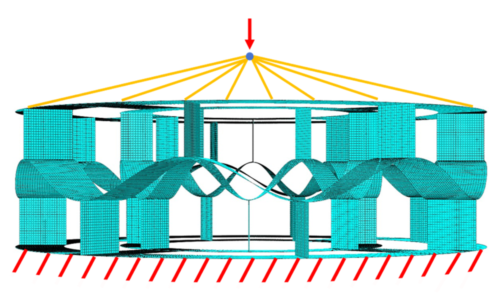
3. Numerical Simulation
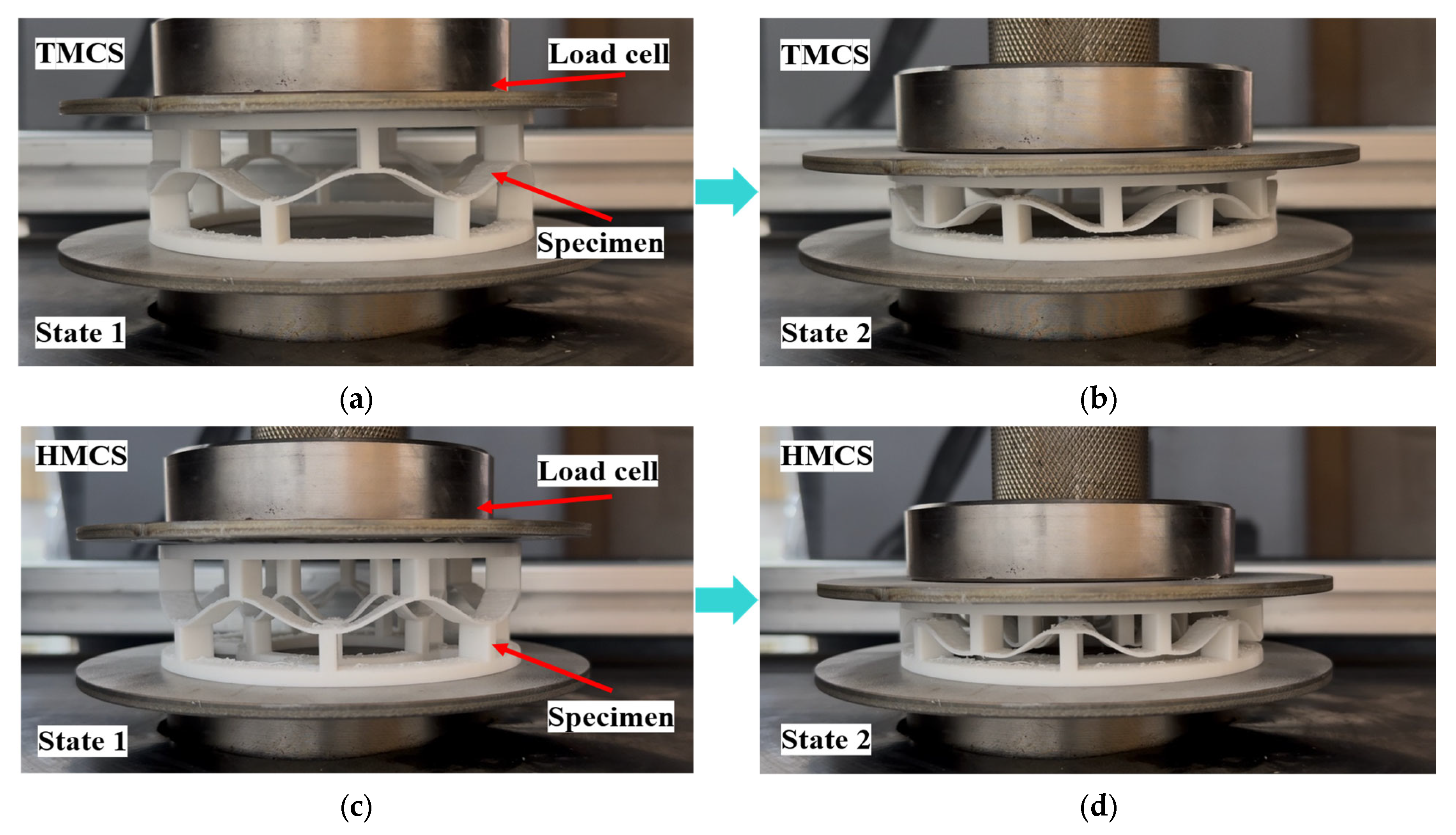
In this section, as shown in Figure 5, finite element analysis models were developed by ABAQUS to study the snap-through behavior of the structure using the (static, general) analysis step. The model was constructed using S4R shell elements, suitable for thin-walled structures. The mesh size was set to 0.5 mm as 1/20 of the cosine beam width to ensure computational accuracy and efficiency. The R3D TPU 95A (thermoplastic polyurethane, Wuhu R3D Technology Co., Ltd., Wuhan, China) material was used for both numerical simulation and experimental fabrication, as it is a commercially available filament commonly used in FDM 3D printing. The elastic modulus (E = 36.991 MPa) and Poisson’s ratio (ν = 0.4) were obtained from the manufacturer’s technical datasheet.
Although additively manufactured polymers can exhibit anisotropic behavior due to the layer-by-layer deposition process, the TPU specimens in this work were printed using a consistent raster angle and uniform wall thickness, and the deformation under quasi-static compression was predominantly axisymmetric. Therefore, an isotropic material assumption was adopted in the finite element analysis [58].
To simulate the snap-though behavior of the structure, the bottom surface of the finite element model was fully fixed, and the top surface was connected to a reference point using MPC constraints. A vertical displacement load was applied directly to this reference point. This reference point is restricted in all degrees of freedom except for the vertical downward direction. The loading displacement is set to twice the height of the cosine beam to ensure that the cosine beam completes the entire snap-though process. In the subsequent simulation analysis of the effect of structural parameters on the HMCS snap-through behaviors, the height h of the HMCS was varied from 6 mm to 10 mm in increments of 0.1 mm. The thickness t ranged from 1 mm to 2.5 mm, also with a step size of 0.1 mm.

4. Experiments

The HMCSs are fabricated by Ultimaker S7 series 3D printer (Ultimaker, Utrecht, The Netherlands) via Fused Deposition Modeling (FDM), and the consumable is chosen to be TPU, which exhibits excellent toughness and large recoverable elastic strain. Quasi-static compression tests were performed to investigate the fundamental mechanical properties, deformation modes, and energy trapping capability of the HMCS, using the INSTRON 5569 (INSTRON, Norwood, MA, USA), a universal vertical press for mechanical property testing. All compression tests were conducted with a constant displacement rate of 2 mm/min.
The compressive deformation process of a layer of the HMCS was recorded by a camera as shown in Figure 6. Here we define the initial morphology as state 1 and the state at the end of the snap-through as state 2. The average of three specimens for each configuration were used as the final experimental results to ensure the reliability of the conclusions. As a comparison, the same experiment was performed for TMCSs.
Figure 7 shows the force–displacement curves of the HMCS and TMCS. The experimental results are in good agreement with the simulation curves, exhibiting similar overall profiles as well as comparable peak and valley forces, which validates the accuracy of the finite element models. The peak force of the HMCS is roughly three times that of the TMCS and the trapped energy is nearly five times.

5. Results and Discussion

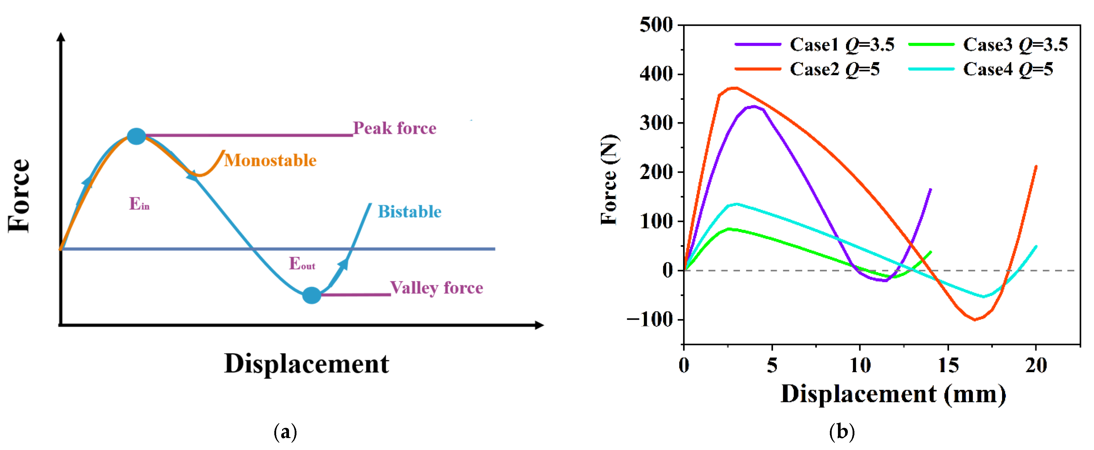
5.1. Energy Trapping and Load-Bearing Behavior

The trapping energy mechanism of multi-stable cylindrical structures is illustrated in Figure 8a. Due to the bi-stable nature of multi-stable cylindrical structures, a portion of the energy is stored within the elements during the transition between stable states. Therefore, the concept of energy trapping (ET) is employed to evaluate the structure’s ability to retain the absorbed energy. Energy absorption [52] refers to the total mechanical work exerted on the structure during the loading process and is typically associated with mono-stable structures. In contrast, energy trapping specifically quantifies the portion of energy that remains stored in the system, which is particularly relevant to bi-stable and multi-stable systems.
In order to assess the structure’s ability to trap energy, the force–displacement curve is integrated along the displacement axis, from which two energy regions, Ein and Eout, are obtained. These two regions represent the energy absorbed and released by the structure during the transition between stable states. In the following analysis, the trapped energy refers to the difference between these two quantities, specifically Ein minus Eout. The area under the curve can be calculated using the following Equation:
E T = 0 d f x d x
S E T = 0 d f x d x M
In the Equation, ET denotes the total energy trapping, SET represents the specific energy trapping, which is the energy trapping per unit mass, x is the displacement variable, d is the maximum displacement, f(x) is the external force corresponding to the displacement x, and M is the mass of the multi-stable structure.
The energy trapping performance of the HMCSs was compared with that of the TMCSs with only an outer ring, as reported in reference [59], as shown in Figure 4. We conducted a comparative study on four different cases with varying structural parameters of the HMCSs and TMCSs. The detailed configurations of the four cases are listed in Table 1.
The specific capacity (SC), defined as SC = P/M (where P is the peak load and M is the structural mass) [52], is adopted in this study as a standard metric for evaluating the load-carrying capability of energy-absorbing structures. As shown in Figure 8b, at Q = 3.5, the SC value of the TMCS is 1.84, whereas that of the HMCS reaches 4.06. At Q = 5, the SC increases to 2.96 for the TMCS and 4.51 for the HMCS. These results indicate that across different height-to-thickness ratios, the HMCS consistently exhibits significantly higher SC values than the TMCS, clearly demonstrating its superior load-carrying capacity. Furthermore, from a mechanical perspective, the slope of the force–displacement curve at any given point corresponds to the stiffness of the structure at that deformation state. As illustrated in Figure 8b, the HMCS consistently exhibits steeper slopes compared to the TMCS across the entire loading process, indicating significantly higher structural stiffness. This further confirms the superior load-bearing characteristics of the HMCS design.
The total trapped energy and specific trapped energy results are presented in Figure 8c,d, respectively. The results show that the HMTSs achieve higher total trapped energy compared to the TMCSs. At Q = 3.5, the energy trapping ability of the HMCS increased by 485.84%, and its specific energy trapping ability increased by 225.95% compared to the TMCS. At Q = 4, the energy trapping ability showed an increase of 367%, while the specific energy trapping ability increased by 162.54%. At Q = 4.5, the energy trapping ability increased by 308.28%, and the specific energy trapping ability increased by 161.65%. At Q = 5, the increases were 284.73% and 156.65%, respectively. Therefore, the HMCSs demonstrate a combination of high energy trapping capacity, superior load-carrying capability, and lightweight structural advantages.

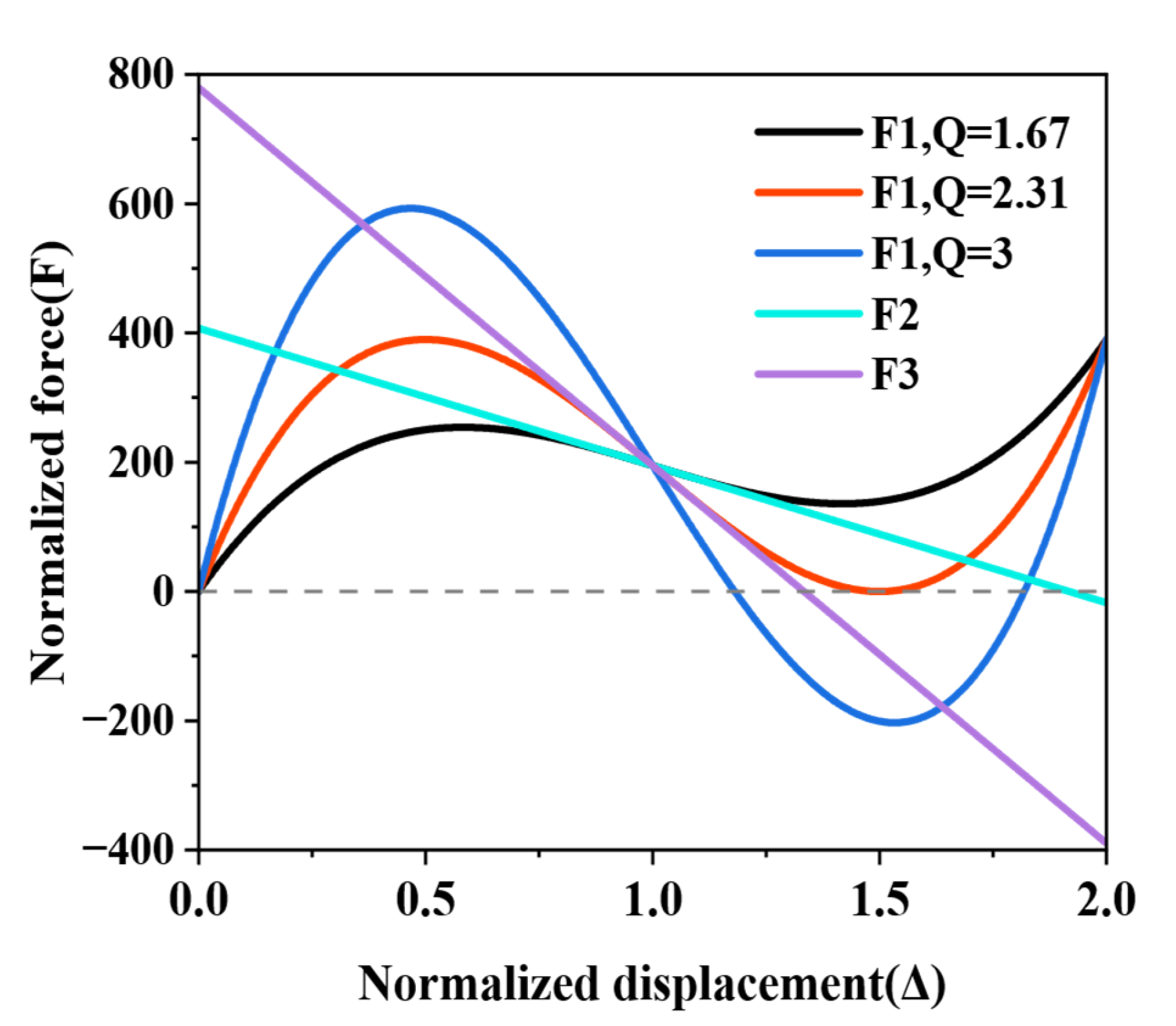
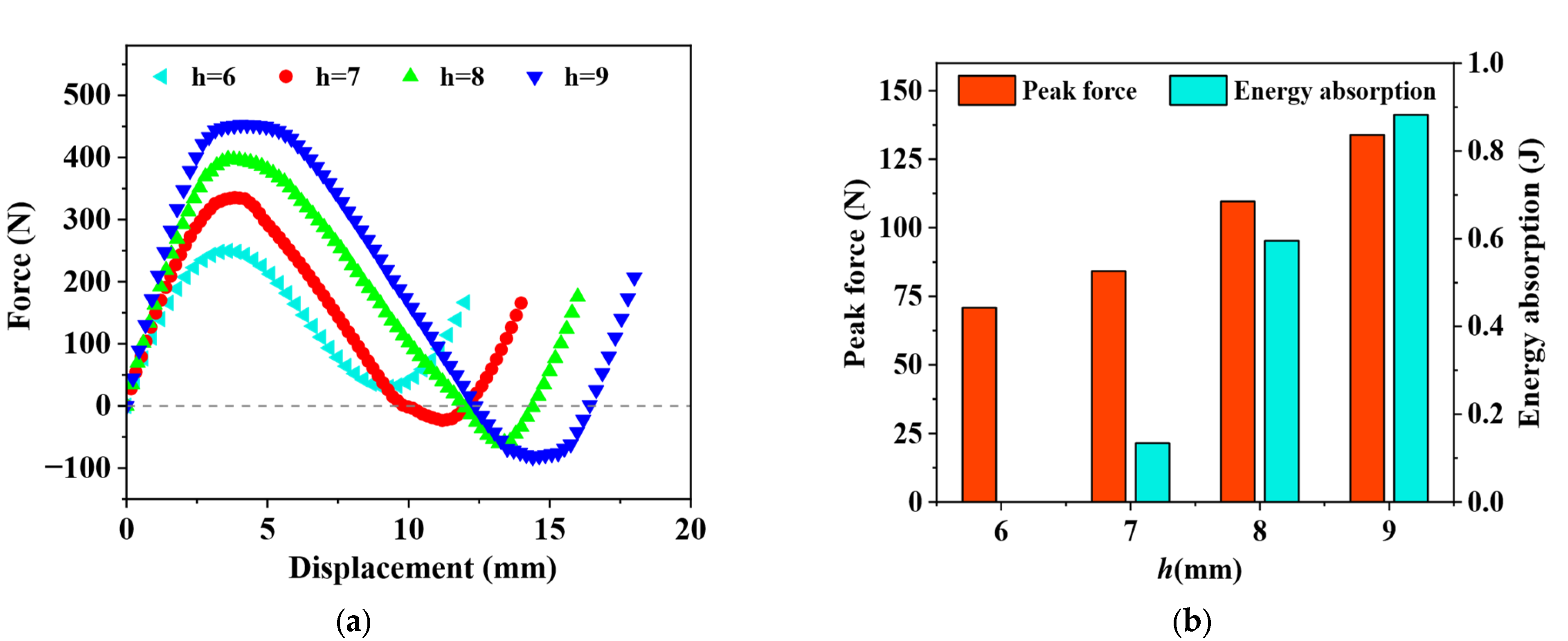
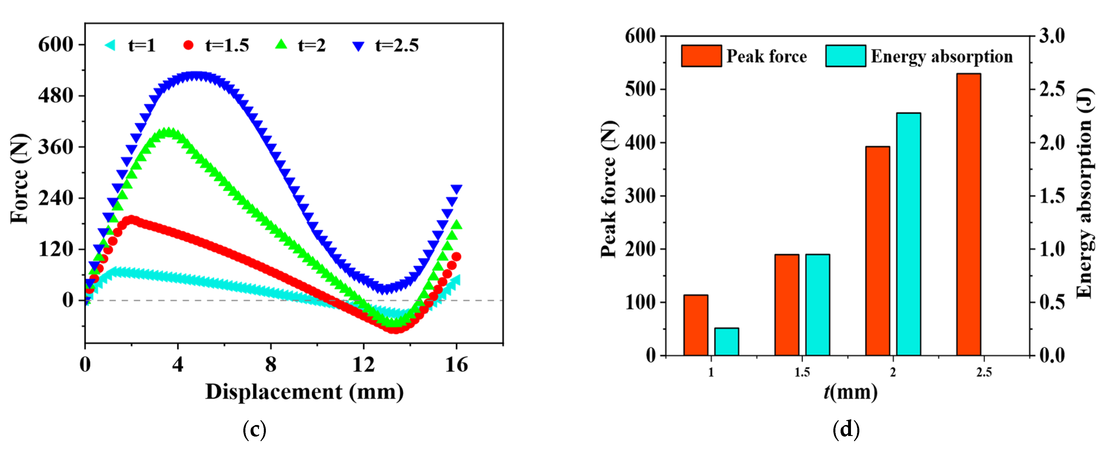
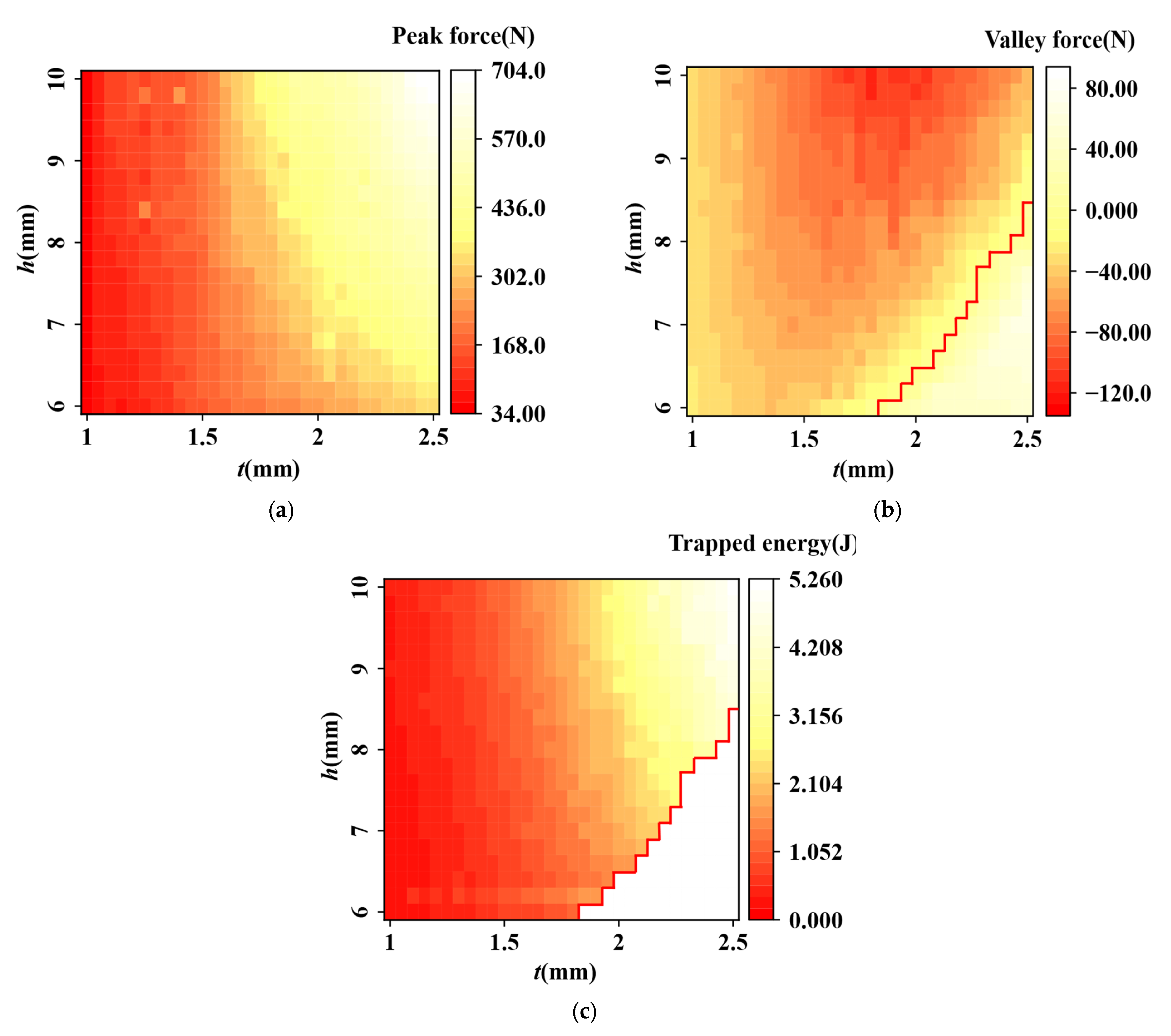
5.2. The Effect of Structural Parameters

Previous studies [59] indicated that the mechanical performance of multi-stable structures is closely related to their geometric parameters. Therefore, the effects of height h and thickness t were investigated separately.
As illustrated in Figure 9a,b, the peak force exhibits an increasing trend with the curved beam height h, indicating enhanced structural stiffness. Notably, when h = 6, the structure demonstrates no energy trapping capability, suggesting the absence of bi-stability. In contrast, for h > 7, the structure not only exhibits bi-stable behavior but also shows a marked increase in trapped energy with further increases in h. As shown in Figure 9c,d, both the peak force and energy trapping capacity increase significantly with the thickness t. Additionally, thicker curved beams tend to exhibit mono-stable behavior, thereby lacking effective energy trapping capability, as exemplified by the HMCS with t = 2.5. Conversely, thinner curved beams, such as those with t = 1, 1.5, and 2, display multi-stability. Therefore, optimal multi-stability in HMCSs requires a critical thickness parameter t.
In summary, height h and thickness t are key parameters influencing the mechanical performance of HMCSs. It is crucial to consider their synergistic effects in the design and application stages to identify boundaries between different response types.
To investigate the combined effects of height h and thickness t and determine the boundaries of different response types, simulations of the HMCSs were performed across a range of geometric parameters: thickness t varied from 1 to 2.2 with an increment of 0.1, and height h varied from 6 to 10 with an increment of 0.1. The parameter l was fixed at 20 mm.
The peak load, representing the maximum load before structural snap-through, typically characterizes the structure’s ability to resist external loading, i.e., initial stiffness. As seen in Figure 10a, the peak load of the HMCSs increases with increases in parameters h and t. Within the selected parameter range, the maximum peak force is approximately 20.7 times greater than the minimum.
Valley load responses are presented in Figure 10b. The valley load corresponds to the minimum load after structural snap-through and is commonly used to identify the bi-stable behavior of negative-stiffness structures. Structures exhibiting negative valley loads are typically considered bi-stable. In Figure 10b, positive and negative valley loads are separated by a red curve, with the negative region shown in yellow-white to the right of this boundary. It can be seen that the valley load exhibits a relatively simple relationship with the height h: the load decreases as h increases. In contrast, the relationship between the valley load and thickness t is more complex. Within the bi-stable region, the valley load first decreases and then increases with increasing t. Conversely, in the mono-stable region, the valley load continuously decreases as t increases.
Figure 10c shows the relationship between energy trapping ability and parameters t and h for the HMCSs. It can be seen that the structure’s energy trapping ability increases with higher t and h values, and parameter t exerts a more pronounced influence on energy trapping compared to parameter h. Maximum energy trapping occurs near the boundary between response types. Although the boundary between mono-stable and bi-stable response types is not constant, the critical parameter ratio remains relatively consistent around h/t ≈ 3.69, serving as a reasonable criterion for response type selection.

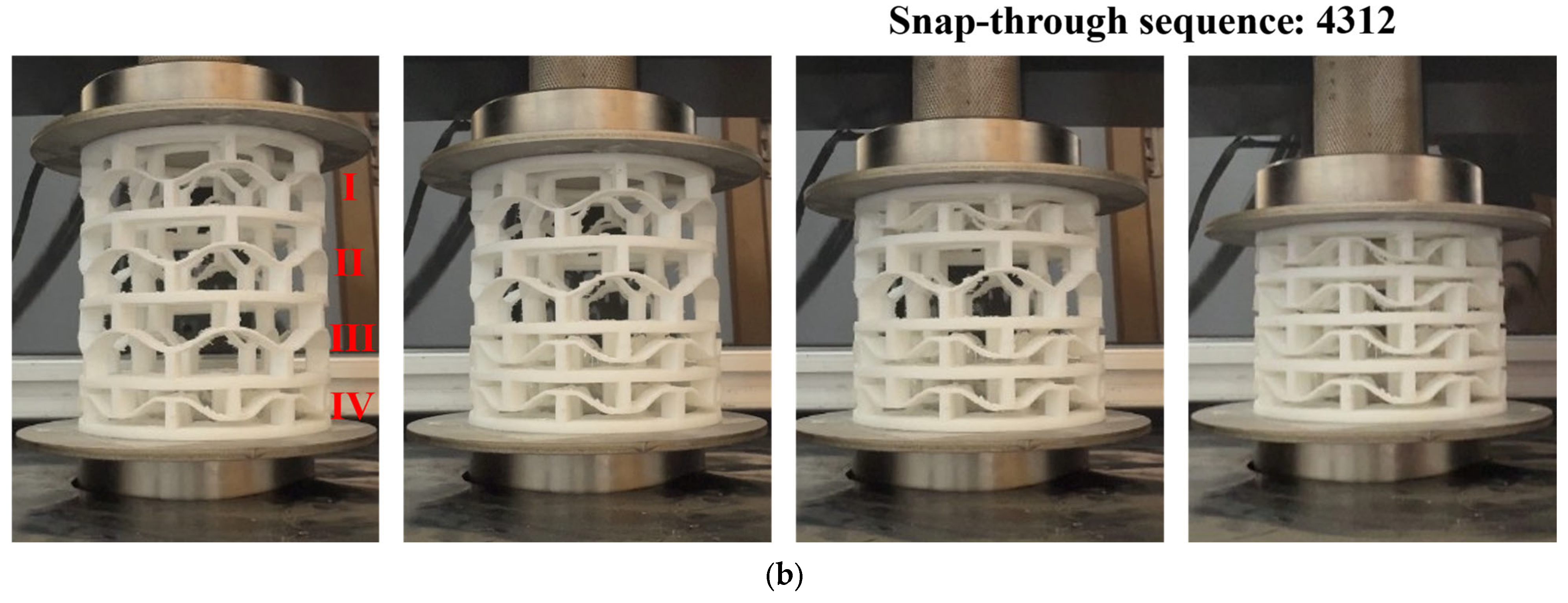
5.3. Tuning Snap-Through Sequence

As illustrated in Figure 11, the HMCS contains four layers, from top to bottom, named as Layer I, Layer II, Layer III, and Layer IV. The corresponding thicknesses of each layer are denoted as t1, t2, t3, and t4. To investigate the effect of different thickness configurations on the snap-through sequence, two configurations were designed and tested, with varying values of thickness t. The detailed structural configurations are listed in Table 2.
When the HMCS is loaded, the snap-through response sequence occurs as shown in Figure 11, where (a) corresponds to Case 1 and (b) corresponds to Case 2. The results show that when the HMCS begins to compress, the layer with the lowest thickness begins to deform first. Once this layer is fully deformed, the remaining layers are captured sequentially based on the increasing thickness of their respective beams. As shown in Figure 12, the four local maxima and minima in the force–displacement curve correspond to the four curved beams with different thicknesses within the multi-layer HMCS. The deformation process of each layer can be divided into three stages, consistent with the structural response described in Section 2. Initial deformation occurs during the first stage, where the structure primarily experiences combined compression and bending. The required force rapidly increases with increasing displacement. Hence, this stage is referred to as the positive stiffness stage. In the second stage, the structure mainly undergoes compression deformation, and the force–displacement curve exhibits elastic instability, revealing a negative stiffness effect. Thus, this stage is defined as the negative stiffness stage. The third stage marks the densification of the structure, during which the curved beams gradually become compacted. As displacement further increases, the required force rises again, and the structure once more exhibits positive stiffness behavior.
The deformation behavior of each layer in the structure corresponds to the elastic instability phenomenon occurring in the curved beams, causing each layer to exhibit a negative stiffness effect. During compression, deformation initially occurs in the thinnest layer (1.0 mm), exhibiting a peak force of 59.3 N, and subsequently propagates to the thickest layer (1.3 mm), reaching a peak force of 91.1 N. As shown in Figure 12, the experimental results agree well with the finite element simulation results, demonstrating similar trends and characteristic peak forces. The overall consistency validates the accuracy of the finite element analysis. From the two structures tested above, it can be learned that the thickness of the curved beams influences the sequence of the snap-through between each layer, so the thickness of the curved beams can be adjusted to tune the snap-through behaviors of the overall structure to obtain metamaterials with customizable properties.

6. Conclusions

This paper proposes a novel hierarchical multi-stable cylindrical structure (HMCS). The mechanical properties of the structure and the influence of its geometric parameters were investigated through a combination of numerical simulations and experimental studies. The main findings are summarized as follows:
(1)
The HMCS inherits all the characteristic mechanical behaviors of traditional multi-stable cylindrical structures (TMCSs), including energy absorption and snap-through behaviors. Compared with the TMCS, the proposed HMCS has significant increases in both total and specific energy absorption. Specifically, in the case tested, the HMCS exhibited approximately a 200% increase in load-carrying capacity, and achieved a total energy trapping of 485% and a specific energy trapping gain of 225% compared to the TMCS.
(2)
The height h and thickness t of the curved beams are identified as critical parameters influencing the performance of the HMCS. While the peak force and energy absorption exhibit relatively straightforward correlations with h and t, the valley force shows a more complex relationship with beam thickness. A critical parameter ratio of h/t ≈ 3.69 was determined, serving as a threshold for distinguishing between mono-stable and bi-stable responses.
(3)
A tuning snap-through sequence design of a multilayer HMCS is achieved by tailoring the thickness of the curved beams. The results reveal that the thicknesses of the curved beams dominate the snap-through behavior in multilayer structures. Deformation initiates from the layer with the lowest stiffness and progresses sequentially through layers with increasing beam thickness.
This work provides a novel strategy for designing high-efficiency energy-absorbing structures. The proposed HMCS offers both theoretical guidance and practical reference for applications in energy absorption, impact mitigation, and advanced mechanical metamaterial systems.

Author Contributions

Y.W., conceptualization, writing—original draft, methodology, software, investigation; M.H., conceptualization, methodology, funding acquisition; Q.T., conceptualization, methodology, funding acquisition, resources, supervision, writing—review and editing, validation; X.C., investigation, software; J.W., validation, software; Q.J., conceptualization, software, supervision, writing—review and editing. All authors have read and agreed to the published version of the manuscript.

Funding

This research was funded by the National Natural Science Foundation of China (grant No. 12202222), Shandong Provincial Natural Science Foundation (grant No. ZR2022QA104), and supported by the Science Foundation of the National Key Laboratory of Science and Technology on Advanced Composites in Special Environments (grant No. JCKYS2024603C012).

Data Availability Statement

The data used to support the findings of this study are included within the article. Further data or information is available from the corresponding author upon request.

Conflicts of Interest

The authors declare no conflicts of interest.

References

  1. Liu, T.; Lin, C.; Zhang, Y.; Cai, J.; Yang, J. Viscoelastic negative stiffness metamaterial with multistage load bearing and programmable energy absorption ability. Int. J. Smart Nano Mater. 2024, 16, 1–23. [Google Scholar] [CrossRef]
  2. Xiao, B.; Liu, Y.; Xu, W.; Wei, R.; Chen, M.; Jiang, H. A bistable honeycomb mechanical metamaterial with transformable Poisson’s ratio and tunable vibration isolation properties. Thin-Walled Struct. 2024, 198, 111718. [Google Scholar] [CrossRef]
  3. Li, N.; Liu, S.; Wu, X.; Wang, J.; Han, Y.; Zhang, X. Mechanical characteristics of a novel rotating star-rhombic auxetic structure with multi-plateau stages. Thin-Walled Struct. 2023, 191, 111081. [Google Scholar] [CrossRef]
  4. Mizzi, L.; Grasselli, L.; Spaggiari, A.; Gatt, R.; Farrugia, P.S.; Grima, J.N. Design of isotropic 2D chiral metamaterials based on monohedral pentagonal tessellations. Thin-Walled Struct. 2023, 187, 110739. [Google Scholar] [CrossRef]
  5. Zhu, S.; Wang, J.; Chen, L.; Liu, T.; Li, W. Negative stiffness metamaterial with directional stability in uniform fields. Thin-Walled Struct. 2024, 194B, 111302. [Google Scholar] [CrossRef]
  6. Ren, L.; Wu, Q.; Li, J.; He, Y.; Zhang, Y.; Zhou, X.; Wu, S.; Liu, Q.; Li, B. 4D printing of customizable and reconfigurable mechanical metamaterials. Int. J. Mech. Sci. 2024, 270, 109112. [Google Scholar] [CrossRef]
  7. Khajehtourian, R.; Kochmann, D.M. Soft Adaptive Mechanical Metamaterials. Front. Robot. AI 2021, 8, 673478. [Google Scholar] [CrossRef]
  8. Wan, M.; Yu, K.; Sun, H. 4D printed programmable auxetic metamaterials with shape memory effects. Compos. Struct. 2022, 279, 114791. [Google Scholar] [CrossRef]
  9. Zhang, Q.; Sun, Y. Novel metamaterial structures with negative thermal expansion and tunable mechanical properties. Int. J. Mech. Sci. 2024, 261, 108692. [Google Scholar] [CrossRef]
  10. Zhang, X.; Ye, H.; Wei, N.; Tao, R.; Luo, Z. Design optimization of multifunctional metamaterials with tunable thermal expansion and phononic bandgap. Mater. Des. 2021, 209, 109990. [Google Scholar] [CrossRef]
  11. Coulais, C.; Teomy, E.; de Reus, K.; Shokef, Y.; van Hecke, M. Combinatorial design of textured mechanical metamaterials. Nature 2016, 535, 529–532. [Google Scholar] [CrossRef] [PubMed]
  12. Ma, H.; Wang, K.; Zhao, H.; Shi, W.; Xue, J.; Zhou, Y.; Li, Q.; Wang, G.; Yan, B. Energy dissipation and shock isolation using novel metamaterials. Int. J. Mech. Sci. 2022, 218, 107464. [Google Scholar] [CrossRef]
  13. Gholikord, M.; Etemadi, E.; Imani, M.; Hosseinabadi, M.; Hu, H. Design and analysis of novel negative stiffness structures with significant energy absorption. Thin-Walled Struct. 2022, 181, 110137. [Google Scholar] [CrossRef]
  14. Jiang, H.; Bednarcyk, B.A.; Le Barbenchon, L.; Chen, Y. Elastically anisotropic architected metamaterials with enhanced energy absorption. Thin-Walled Struct. 2023, 192, 111115. [Google Scholar] [CrossRef]
  15. Li, Y.; Deng, Z.; Yan, G.; Gao, G. Wave propagation in two-dimensional elastic metastructures with triangular configuration. Thin-Walled Struct. 2022, 181, 110043. [Google Scholar] [CrossRef]
  16. Zhou, J.; Pan, H.; Cai, C.; Xu, D. Tunable ultralow frequency wave attenuations in one-dimensional quasi-zero-stiffness metamaterial. Int. J. Mech. Mater. Des. 2021, 17, 285–300. [Google Scholar] [CrossRef]
  17. Bobbert, F.S.L.; Janbaz, S.; van Manen, T.; Li, Y.; Zadpoor, A.A. Russian doll deployable meta-implants: Fusion of kirigami, origami, and multi-stability. Mater. Des. 2020, 191, 108624. [Google Scholar] [CrossRef]
  18. Bodaghi, M.; Liao, W.H. 4D printed tunable mechanical metamaterials with shape memory operations. Smart Mater. Struct. 2019, 28, 045019. [Google Scholar]
  19. Yang, H.; Ma, L. 1D and 2D snapping mechanical metamaterials with cylindrical topology. Int. J. Solids Struct. 2020, 204–205, 220–232. [Google Scholar] [CrossRef]
  20. Zhang, Y.; Tichem, M.; van Keulen, F. A novel design of multi-stable metastructures for energy dissipation. Mater. Des. 2021, 212, 110234. [Google Scholar] [CrossRef]
  21. Zhang, L.; Pan, F.; Ma, Y.; Yang, K.; Guo, S.; Chen, Y. Bistable reconfigurable origami metamaterials with high load-bearing and low state-switching forces. Extreme Mech. Lett. 2023, 63, 102064. [Google Scholar] [CrossRef]
  22. Hu, H.; Xia, Z.; Tao, Q.; Ye, Z.; Yuan, K.; Song, L. Self-unfolding properties of smart grid-reinforced membrane origami. J. Compos. Sci. 2024, 8, 64. [Google Scholar] [CrossRef]
  23. Sun, Y.; Song, K.; Ju, J.; Zhou, X. Curved-creased origami mechanical metamaterials with programmable stabilities and stiffnesses. Int. J. Mech. Sci. 2024, 262, 108729. [Google Scholar] [CrossRef]
  24. Zhou, Y.; Jiang, D.; Wang, L.; Xiang, P.; Jia, L.-J. Cushioning performance of origami negative Poisson’s ratio honeycomb steel structure. Thin-Walled Struct. 2024, 204, 112284. [Google Scholar] [CrossRef]
  25. Li, Z.; Xie, C.; Li, F.; Wu, D.; Hu, N. Heterogeneous geometric designs in auxetic composites toward enhanced mechanical properties under various loading scenarios. Compos. Commun. 2023, 38, 101499. [Google Scholar] [CrossRef]
  26. Danish, B.; Anilkumar, P.M.; Rao, B.N. Suppression of cross-well vibrations of a bistable square cross-ply laminate using an additional composite strip. Int. J. Dyn. Control 2023, 11, 2680–2690. [Google Scholar] [CrossRef]
  27. Zhang, K.; Qi, L.; Zhao, P.; Zhao, C.; Deng, Z. Buckling induced negative stiffness mechanical metamaterial for bandgap tuning. Compos. Struct. 2023, 304, 116421. [Google Scholar] [CrossRef]
  28. Liu, T.; Deng, R.; Zhang, Y.; Yang, J.; Cai, J. Composite negative stiffness structure with tunable and temperature-dependent properties induced by viscoelastic and shape-memory materials. Compos. Commun. 2024, 48, 101937. [Google Scholar] [CrossRef]
  29. Debeau, D.A.; Seepersad, C.C.; Haberman, M.R. Impact behavior of negative stiffness honeycomb materials. J. Mater. Res. 2018, 33, 290–299. [Google Scholar] [CrossRef]
  30. Zhang, Y.; Tichem, M.; van Keulen, F. Concept and design of a metastructure-based multi-stable surface. Extrem. Mech. Lett. 2022, 51, 101553. [Google Scholar] [CrossRef]
  31. Chen, B.; Chen, L.; Du, B.; Liu, H.; Li, W.; Fang, D. Novel multifunctional negative stiffness mechanical metamaterial structure: Tailored functions of multi-stable and compressive mono-stable. Compos. B Eng. 2021, 204, 108501. [Google Scholar] [CrossRef]
  32. Qiu, J.; Lang, J.H.; Slocum, A.H. A curved-beam bistable mechanism. J. Microelectromech. Syst. 2004, 13, 137–146. [Google Scholar] [CrossRef]
  33. Hua, J.; Zhou, Y.; Chen, C.Q. Design and analysis of a tunable multistable mechanical metamaterial. Int. J. Mech. Sci. 2024, 272, 109170. [Google Scholar] [CrossRef]
  34. Hua, J.; Lei, H.; Gao, C.F.; Guo, X.; Fang, D. Parameters analysis and optimization of a typical multistable mechanical metamaterial. Extreme Mech. Lett. 2020, 35, 100640. [Google Scholar] [CrossRef]
  35. Zhang, X.; Hao, H.; Tian, R.; Xue, Q.; Guan, H.; Yang, X. Quasi-static compression and dynamic crushing behaviors of novel hybrid re-entrant auxetic metamaterials with enhanced energy-absorption. Compos. Struct. 2022, 288, 115399. [Google Scholar] [CrossRef]
  36. Che, K.; Rouleau, M.; Meaud, J. Temperature-tunable time-dependent snapping of viscoelastic metastructures with snap-through instabilities. Extreme Mech. Lett. 2019, 32, 100528. [Google Scholar] [CrossRef]
  37. Yan, S.; Wu, L.; Wen, Y.; Sun, J.; Zhou, J. Snap-through instability in mechanical metamaterials. Respons. Mater. 2025, 3, e20240035. [Google Scholar]
  38. Seyedkanani, A.; Akbarzadeh, A. Magnetically assisted rotationally multistable metamaterials for tunable energy trapping–dissipation. Adv. Funct. Mater. 2022, 32, 2207581. [Google Scholar] [CrossRef]
  39. Dong, T.; Zhang, W.; Dong, M. The novel morphing airfoil based on the bistable composite laminated shell. Nonlinear Dyn. 2023, 111, 17667–17685. [Google Scholar] [CrossRef]
  40. Che, K.; Yuan, C.; Wu, J.; Qi, H.J.; Meaud, J. Three-dimensional-printed multistable mechanical metamaterials with a deterministic deformation sequence. J. Appl. Mech. 2017, 84, 011004. [Google Scholar] [CrossRef]
  41. Meaud, J.; Che, K. Tuning elastic wave propagation in multistable architected materials. Int. J. Solids Struct. 2017, 122–123, 69–80. [Google Scholar] [CrossRef]
  42. Che, K.; Yuan, C.; Qi, H.J.; Meaud, J. Viscoelastic multistable architected materials with temperature-dependent snapping sequence. Soft Matter 2018, 14, 2492–2499. [Google Scholar] [CrossRef] [PubMed]
  43. Sun, S.; An, N.; Wang, G.; Li, M.; Zhou, J. A novel bistable structure with temperature-dependent transition. J. Appl. Phys. 2021, 129, 044903. [Google Scholar] [CrossRef]
  44. Zouhri, K.; Mohamed, M.; Erol, A.; Liu, B.; Appiah-Kubi, P. Innovative bistable composites for aerospace and high-stress applications: Integrating soft and hard materials in experimental, modeling, and simulation studies. Materials 2024, 17, 4280. [Google Scholar] [CrossRef]
  45. Mozafari, H.; Distefano, F.; Epasto, G.; Gu, L.; Linul, E.; Crupi, V. Design of an innovative hybrid sandwich protective device for offshore structures. J. Mar. Sci. Eng. 2022, 10, 1385. [Google Scholar] [CrossRef]
  46. Wang, L.; Kim, H. Bistable CFRP structures for automotive crash boxes: Experimental and numerical validation. Thin-Walled Struct. 2023, 182, 110234. [Google Scholar]
  47. Wang, C.; Guo, H.; Liu, R.; Deng, Z.; Chen, Y.; You, Z. Reconfigurable origami-inspired multistable metamorphous structures. Sci. Adv. 2024, 10, eadk8662. [Google Scholar] [CrossRef]
  48. Ji, S.; Wang, F.; Wang, J.; Wang, Z.; Wang, C.; Wei, Y. Dynamic responses and energy absorption of mechanical metamaterials composed of buckling beams. J. Vib. Eng. Technol. 2024, 12, 1249–1261. [Google Scholar] [CrossRef]
  49. Tan, S.; Pan, D.; Wu, Z. Multi-stable metastructure with multi-layer and multi-degree of freedom: A numerical and experimental investigation. Mater. Des. 2024, 240, 112859. [Google Scholar] [CrossRef]
  50. Ju, X.; Li, S.; Zhang, Y.; Wu, P.; Li, Y. Design of multi-stable metamaterial cell with improved and programmable energy trapping ability based on frame reinforced curved beams. Thin-Walled Struct. 2024, 202, 112120. [Google Scholar] [CrossRef]
  51. Yao, X.; Liu, K.; Dong, Q.; Li, X.; Ma, C.; Hu, N. Tunable and recoverable energy absorption of foam-embedded architected cellular composite material at multiple strain rates. Compos. Struct. 2024, 329, 117745. [Google Scholar] [CrossRef]
  52. Song, Y.; Ruan, S.; Hao, N.; Liu, Y.; Zhang, S. A novel cylindrical sandwich plate inspired by beetle elytra and its compressive properties. Sci. China Technol. Sci. 2024, 67, 3465–3476. [Google Scholar] [CrossRef]
  53. Dong, Y.; Yu, T.; Zhang, Z. Design and mechanical analysis of 3D negative-stiffness curved domes with Bessel-functional profile. Compos. Struct. 2023, 30, 116422. [Google Scholar] [CrossRef]
  54. Tan, X.; Wang, B.; Wang, L.; Zhu, S.; Chen, S.; Yao, K.; Xu, P. Effect of beam configuration on its multistable and negative stiffness properties. Compos. Struct. 2022, 286, 115308. [Google Scholar] [CrossRef]
  55. Li, Y.H.; Dong, Y.H.; Qin, Y.; Lv, H.W. Nonlinear forced vibration and stability of an axially moving viscoelastic sandwich beam. Int. J. Mech. Sci. 2018, 138–139, 131–145. [Google Scholar] [CrossRef]
  56. Guan, Y.; Ge, X. Dynamic modeling and analysis of the central rigid body-Timoshenko beam model based on unconstrained modes. Appl. Math. Mech. 2022, 43, 156–165. [Google Scholar]
  57. Wang, Y.; Fang, Y.; Li, L.; Zhang, D.; Liao, W.H.; Fang, J. Dynamic modeling and vibration suppression of a rotating flexible beam with segmented active constrained layer damping treatment. Aerospace 2023, 10, 1010. [Google Scholar] [CrossRef]
  58. Hohimer, C.; Christ, J.; Aliheidari, N.; Mo, C.; Ameli, A. 3D printed thermoplastic polyurethane with isotropic material properties. Proc. SPIE 2017, 10168, 101680E. [Google Scholar]
  59. Tan, X.; Wang, B.; Chen, S.; Zhu, S.; Sun, Y. A novel cylindrical negative stiffness structure for shock isolation. Compos. Struct. 2019, 214, 397–405. [Google Scholar] [CrossRef]
Figure 1. Three buckling modes of a clamped beam.
Applsci 15 07748 g001
Figure 2. Normalized force versus normalized displacement for three different modes.
Applsci 15 07748 g002
Figure 3. (a) Two different deformation states of the cosinusoidal curved beam under a transverse force f; (b) the geometry features of the unit cell; (c) axonometric view of the unit cell.
Applsci 15 07748 g003
Figure 4. The geometry of the multilayer HMCS.
Applsci 15 07748 g004
Figure 5. Finite element model of HMCS.
Applsci 15 07748 g005
Figure 6. (a,b) Snap process of TMCS during quasi-static compression experiments; (c,d) snap process of HMCS during quasi-static compression experiments.
Applsci 15 07748 g006
Figure 7. Comparison of simulation and experimental results between HMCS and TMCS.
Applsci 15 07748 g007
Figure 8. (a) Typical force–displacement relationship of mono-stable and bi-stable structures; (b) force–displacement curves of the four cases; (c) trapped energy; (d) specific trapped energy.
Applsci 15 07748 g008aApplsci 15 07748 g008b
Figure 9. Effect of height and thickness on load–displacement curves, peaks, and energy absorption.
Applsci 15 07748 g009aApplsci 15 07748 g009b
Figure 10. (a) Relationship between the peak force and the geometric parameters t and h; (b) relationship between the valley force and the geometric parameters t and h; (c) relationship between the energy trapping performance and the geometric parameters t and h.
Applsci 15 07748 g010
Figure 11. Snap-through sequences of two HMCSs.
Applsci 15 07748 g011aApplsci 15 07748 g011b
Figure 12. Force–displacement curves of case 4321.
Applsci 15 07748 g012
Table 1. Structural parameters of the four cases.
CasehtQ
Hierarchical multi-stable cylindrical structure17 mm2 mm3.5
210 mm2 mm5
Traditional multi-stable cylindrical structure37 mm2 mm3.5
410 mm2 mm5
Table 2. Structural parameters of the two cases.
Caset1t2t3t4
11.3 mm1.2 mm1.1 mm1.0 mm
21.2 mm1.3 mm1.1 mm1.0 mm
Disclaimer/Publisher’s Note: The statements, opinions and data contained in all publications are solely those of the individual author(s) and contributor(s) and not of MDPI and/or the editor(s). MDPI and/or the editor(s) disclaim responsibility for any injury to people or property resulting from any ideas, methods, instructions or products referred to in the content.

