Abstract
With the rapid urbanization and increasing development of underground spaces, foundation pit groups in complex geological environments encounter considerable challenges in deformation control. These challenges are especially prominent in cases of adjacent constructions, complex geology, and environmentally sensitive areas. Nevertheless, existing research is lacking in systematic analysis of construction sequencing and the interaction mechanisms between foundation pit groups. This results in gaps in comprehending stress redistribution and optimal excavation strategies for such configurations. To address these gaps, this study integrates physical model tests and PLAXIS 3D numerical simulations to explore the Nanjing Jiangbei New District Phase II pit groups. It concentrates on deformations in segmented and adjacent configurations under varying excavation sequences and spacing conditions. Key findings reveal that simultaneous excavation in segmented pit groups optimizes deformation control through symmetrical stress relief via bilateral unloading, reducing shared diaphragm wall displacement by 18–25% compared to sequential methods. Sequential excavations induce complex soil stress redistribution from asymmetric unloading, with deep-to-shallow sequencing minimizing exterior wall deformation (≤0.12%He). For adjacent foundation pit groups, simultaneous excavation achieves minimum displacement interference, while phased construction requires prioritizing large-section excavation first to mitigate cumulative deformations through optimized stress transfer. When the spacing-to-depth ratio (B/He) is below 1, horizontal displacements of retaining structures increase by 43% due to spacing effects. This study quantifies the effects of excavation sequences and spacing configurations on pit group deformation, establishing a theoretical framework for optimizing construction strategies and enhancing retaining structure stability. The findings are highly significant for underground engineering design and construction in complex urban geological settings, especially in high-density areas with spatial and geotechnical constraints.
1. Introduction
With accelerating urbanization intensifying land scarcity, underground space development has transitioned from localized structures to metropolitan-scale networks. Contemporary foundation pit projects now routinely encompass multi-level complexes exceeding 40 m depth—including large-section metro interchanges, integrated commercial hubs, and underground logistics systems—reflecting an industry-wide shift toward megascale engineering. This paradigm evolution demands innovative solutions for deep excavation challenges [,,]. Large shopping malls, underground complexes, and transportation hubs have become increasingly common and complex, particularly in densely populated metropolitan areas. These projects often involve the simultaneous or overlapping construction of multiple adjacent foundation pits, rather than single pits. When affected by surrounding developments and integrated construction methods, combined foundation pit groups, including irregular interconnected and nested pits, emerge []. As shown in Figure 1, based on their functional use and spatial relationships, these groups can be categorized into three main types:

Figure 1.
Foundation pit groups with different layout configurations.
- Adjacent pits: Separated by a soil wall or structure.
- Segmented pits: A single large pit divided into smaller sections constructed sequentially.
- Interconnected pits: Pits sharing a common boundary or connected structure.
Studying the mutual influences and stress–deformation principles during their excavation is a complex issue. This paper takes the Phase II underground space project in the central area of Jiangbei New District, Nanjing, as the case study. The project involves ultra-deep construction pits, defined as excavations exceeding 20 m in depth according to the Chinese Technical Code for Retaining and Protection of Building Foundation Excavations. This depth threshold represents scenarios requiring specialized engineering solutions due to compounded challenges from groundwater pressure, soil–structure interaction, and construction risks. It focuses on the construction sequencing challenges of large-scale, multi-combination foundation pit groups, specifically addressing the following:
- Deep-to-shallow: Excavating deeper sections prior to shallower sections.
- Shallow-to-deep: Excavating shallower sections prior to deeper sections.
- Synchronous: Simultaneous excavation of adjacent/segmented sections.
This study systematically investigates stress redistribution and deformation mechanisms under these sequences and varying pit spacings (B/He ratios). Additionally, it addresses key technical issues, such as the stress and deformation characteristics of retaining structures under sequential or simultaneous excavation of foundation pit groups.
In recent years, scholars worldwide have employed various methods to study the deformation characteristics of foundation pit excavation and its impact on surrounding structures [,,]. In existing structure impact and deformation control, Shao et al. [], via the Shenyang Metro Line 1 case, used numerical simulation and on-site monitoring to prove that new long foundation pit construction causes existing metro structure displacement, and cross-sections need focused monitoring of support axial force and soil settlement. Liu et al. [], through the Nanjing tunnel project numerical simulation, found that new cut-and-cover tunnels can cause heaving of existing underlying tunnels, and phased excavation can reduce heave by 30–50%. Ma et al. [], by combining numerical simulation with field investigation, showed that when tunnels undercross existing stations, existing pile foundations with tube curtain support can effectively restrain station settlement, but multiple control measures like surface grouting are needed. Huang et al. [], via the Wuhan case numerical simulation, found that deep foundation pit excavation can cause adjacent tunnel structures to have additional bending moments and shear forces, with the influence range positively related to soil parameters and excavation depth. Peng et al [], for the Beijing elevated bridge foundation pit project, proposed that pier displacement control requires real-time monitoring and dynamic support scheme adjustment to lower track structure deformation risk. In soft soil foundation pit deformation characteristics and sectional excavation, Lin et al. [], taking the Hangzhou soft soil foundation pit as an example, pointed out through numerical analysis that large-scale sectional excavation can greatly cut overall foundation pit deformation, yet sectional sequence optimization is needed to balance supporting structure forces. Ge et al. [], based on the Nanjing case, proposed that in soft soil foundation pit excavation, the Hardening Soil Small-Strain (HSS) model can more accurately simulate surrounding soil deformation, and soil reinforcement in the active zone is more effective for deformation control than that in the passive zone. Based on new technology and intelligent monitoring, Pan et al. [] developed a digital twin intelligent monitoring system, solving traditional methods’ inability to predict risks in real time. Its data-driven model updates have greatly improved deformation prediction accuracy. Yu et al. [] put forward the capsule grouting expansion technology simplified theory, offering a quantification tool for pile foundation deformation control. The combination of virtual images and finite difference method in their approach can accurately predict grouting effects.
Existing research on foundation pit groups has predominantly focused on case-specific optimizations of construction schemes, with limited attention to the mechanical interactions between adjacent retaining structures [,,]. While numerical simulations and field measurements are widely employed, their effectiveness is constrained by parameter sensitivity and operational complexity [,], respectively. Laboratory model tests [], particularly cost-effective scaled models, offer controlled insights into deformation patterns but remain underutilized for analyzing multi-pit configurations. Current urban projects increasingly involve adjacent or segmented pits [,,], yet systematic investigations into stress redistribution mechanisms under varying construction sequences (e.g., deep-to-shallow vs. synchronous excavation) and spacing effects (e.g., B/He thresholds) are lacking. This gap hinders the development of practical guidelines for mitigating deformation risks in spatially constrained environments, necessitating a comprehensive approach to unravel the interplay between excavation strategies and geotechnical behavior. In pit group projects, the excavation sequence and spacing (B/He ratio) of adjacent pits significantly affect the deformation and stability of retaining structures. In dense urban areas with complex geology, narrow spacing can cause soil stress overlapping, worsening mutual structural disturbance [,]. Different excavation sequences also influence stress redistribution by altering soil unloading paths. The main research gaps are as follows: First, the critical threshold of pit spacing has not been quantitatively analyzed, making it hard to design safe spacing under different geological conditions. Second, excavation sequence optimization relies too much on engineering experience, causing uncertainty in deformation prediction and construction planning for complex pit groups.
To address these gaps, this study integrates physical model tests and PLAXIS 3D numerical simulations. Section 2 details the experimental methodology, including scaled model design, instrumentation, and constitutive model selection (HSS model). Section 3 presents deformation results for segmented (Section 3.1) and adjacent (Section 3.2) pit configurations under different sequences, supplemented by parametric analysis of spacing effects (Section 3.3). Section 4 discusses optimization strategies and quantifies critical spacing thresholds. Conclusions and limitations are summarized in Section 5.
Notable limitations include the following: (1) homogeneous sand used in physical models may not fully represent stratified natural soils; (2) scaling effects in model tests could influence deformation magnitudes; (3) groundwater–seepage coupling was not considered in simulations.
2. Materials and Methods
This section integrates experimental and numerical approaches to systematically investigate excavation sequencing effects in foundation pit groups. The physical model tests were designed based on typical engineering scenarios in the Nanjing Jiangbei New District Phase II project, where segmented and adjacent pit configurations face challenges of asymmetric stress redistribution and cumulative deformations under spatial constraints. The scaling principles (1:100) adhere to the similarity laws for geotechnical centrifuge modeling, ensuring kinematic consistency between model and prototype behaviors. Material selections (e.g., uniform sand) were validated against the Quaternary alluvial sands dominant in the Yangtze River Delta region, as characterized in Section 2.1.3.
2.1. Experimental Setup
2.1.1. Model Test Design
Indoor physical model tests were first conducted to investigate the excavation sequence and deformation characteristics of foundation pit groups, as shown in Figure 2. Physical model tests were designed and carried out for separated foundation pits and adjacent foundation pits (Figure 3) under various excavation sequences. To accurately capture the deformation patterns of the retaining structures, strain gauges were installed on the surfaces of the diaphragm walls for real-time monitoring during the tests. This approach systematically recorded and analyzed the deformation behavior of the enclosure structures during the excavation process. The test results are valuable for understanding the stress and deformation characteristics of retaining structures under different construction sequences and provide a reliable reference for subsequent theoretical analysis and numerical simulation studies.

Figure 2.
Schematic diagram of the model test (mm).

Figure 3.
Plan layout diagram of model test (mm).
2.1.2. Materials and Equipment
This part introduces the materials and experimental equipment used in the physical model tests. It first describes the test chamber and data acquisition systems, and then details the selection methods and construction methods for the diaphragm walls and supporting structures. Then, it characterizes the soil properties used in the tests and explains the measurement techniques employed to capture deformation data.
The model test was conducted at Nanjing Saibao Hydraulic Equipment Co., Ltd., Nanjing, China. The reinforced concrete model box had dimensions of 5000 mm × 3000 mm × 2700 mm (length × width × height). The data acquisition system is an automated system designed for collecting, storing, and managing data. It gathers data from multiple sources (e.g., sensors, databases, networks, or files) and stores them in a centralized location for analysis and use. In this model test, the DH3816 static strain testing system from Donghua Testing was employed as the data acquisition system. Resistance strain gauges were used as sensors to measure the strain data of the diaphragm wall. The data were transmitted to a computer via the acquisition instrument for analysis and processing.
In this model test, steel plates were used to simulate the diaphragm walls in the engineering project. The steel plates had a wall thickness of 3 mm and an elastic modulus of E = 220 GPa. The steel plates were welded together to form a 0.5 m × 1 m outer frame of the diaphragm wall, as shown in Figure 4. Rigid PVC hollow circular tubes were used to simulate the support system. The PVC tubes had an outer diameter of 20 mm, a wall thickness of 2 mm, and an elastic modulus of E = 3.13 GPa. Several PVC tube supports with lengths of 700 mm, 500 mm, and 200 mm were used in the test.
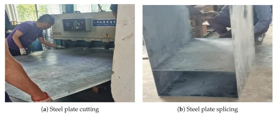
Figure 4.
Experimental setup.
2.1.3. Soil Preparation
The test soil consisted of uniform sand, with a sand layer thickness of 2.7 m in the model box. This material was selected for its representative behavior in foundation pit engineering, particularly its similarity to the Quaternary alluvial sands prevalent in the Yangtze River Delta region where the case study (Nanjing Jiangbei New District) is located. The hydraulic conductivity and shear strength characteristics align with typical silty sands encountered in urban underground projects across eastern China. The soil parameters were determined through geotechnical tests, while the remaining parameters were assigned based on the recommended values from the small-strain soil hardening constitutive model, laying the groundwork for subsequent finite element software parameter analysis, as shown in Table 1. To ensure uniformity and achieve representative compaction, the sand was placed in controlled 100 mm layers with each layer receiving uniform compaction using standard laboratory equipment. The compaction energy was calibrated to attain a relative density consistent with typical engineering fills ( 65–75%), while surface elevation tolerance was maintained within ±2 mm after each compaction stage. To ensure the uniformity and density of the test soil, the sand was filled in layers and compacted during the filling process, with strict control over the layer height and post-compaction elevation. After sieving, particles larger than 0.075 mm accounted for 79.6% of the total soil weight, while particles smaller than 0.25 mm accounted for 54.4% of the total soil weight.

Table 1.
Basic properties of the sand.
2.2. Instrumentation and Data Acquisition
Six strain gauges were installed at different depths along the centerline of each diaphragm wall, with gauges mounted on both sides of the wall, as illustrated in Figure 5a. The horizontal displacement at each location was determined by averaging the measurements from the strain gauges on both sides. The installation process of the strain gauges is depicted in Figure 5b.
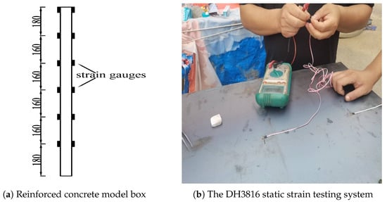
Figure 5.
Horizontal displacement measurement.
This part describes the detailed experimental procedures employed to investigate the deformation characteristics of diaphragm walls under different excavation sequences in segmented and adjacent foundation pit configurations with three primary phases: preparation, excavation, and data analysis.
2.2.1. Preparation Phase
First, all required materials and equipment for the experiment were prepared. The parameters of the soil, steel plates, and rigid PVC hollow circular tubes were obtained through experiments. The steps for strain gauge installation and the operation of the DH3816 static strain measurement system were thoroughly understood. Next, the steel plates were welded together according to the design to simulate the diaphragm wall. Finally, a pit was pre-excavated in the model box, and the completed diaphragm wall was placed horizontally, ensuring that each steel plate was perpendicular to the base. The surrounding soil was backfilled and leveled, as shown in Figure 6.
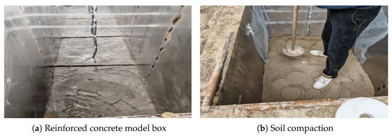
Figure 6.
Test preparation.
2.2.2. Excavation Phase
Two excavation cases were established in this test: simultaneous excavation and sequential excavation. In the simultaneous excavation case, both pits were excavated concurrently. When reaching the elevation for the first-level strut installation, struts were installed simultaneously in both pits, as shown in Figure 7. Subsequent excavation proceeded only after the first-level struts had been installed in both pits. This procedure was repeated for subsequent levels. In the sequential excavation case, one pit was excavated first. Upon reaching the strut installation elevation, struts were installed. Excavation continued after strut installation until the pit was fully excavated. Only then did excavation commence on the second pit, as shown in Figure 8 and Figure 9. The first condition involved synchronous excavation of pits A and B, specifically: Phase 1 excavated earthwork A➀ and B➀, Phase 2 excavated A➁ and B➁, and Phase 3 excavated A➂. The second condition followed a deep-to-shallow sequence for pits A and B, specifically: Phases 1–3 sequentially excavated earthwork ➀➁➂ of Pit A, followed by Phases 4 and 5, which excavated earthwork ➀➁ of Pit B. The third condition adopted a shallow-to-deep excavation approach, specifically: Phases 1 and 2 sequentially excavated earthwork ➀➁ of Pit B, followed by Phases 3–5 excavating earthwork ➀➁➂ of Pit A. During the excavation, strain data from the diaphragm walls were uploaded to a computer via a data acquisition system.
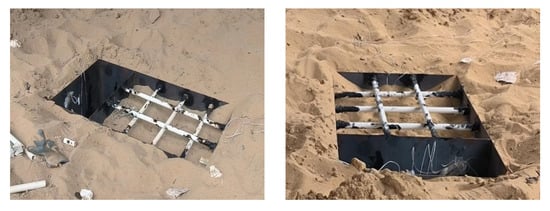
Figure 7.
Test excavation process.
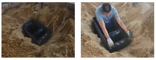
Figure 8.
Backfilling of the diaphragm wall installation.

Figure 9.
Excavation stages.
2.2.3. Data Processing and Analysis Phase
The wall displacement data were processed, and horizontal displacement curves of the retaining structure model plate at each excavation step were plotted using Origin software for analysis. For clarity, the rightward direction was defined as positive and the leftward direction as negative, based on the global coordinate system, to analyze the deformation trend of the retaining wall.
2.3. Numerical Simulation Framework
2.3.1. Finite Element Modeling
Indoor model tests simulate real-world excavation by scaling down structural dimensions, while they are still able to provide controlled, tangible insights into deformation behaviors under different construction sequences. However, these tests are limited by factors such as experimental equipment and conditions, resulting in a limited number of simulated working conditions. On the other hand, numerical simulations extended these insights across a broader set of conditions—such as varied spacing configurations—that were impractical to physically test. This combination ensures both the rigor of controlled experimentation and the flexibility of comprehensive parametric analyses. Therefore, this section will use numerical simulation to replicate the model tests and investigate the mutual influences of construction under more working conditions. Numerical simulations were performed using PLAXIS 3D (Version 22.03) employing 10-node tetrahedral elements (TET10) with three translational degrees of freedom per node (). The mesh was refined to element sizes of 20–40 mm in critical zones (retaining walls) and coarsened to 60–100 mm in far-field regions, resulting in a total of 25,382 elements and 38,573 nodes. This discretization generated a system of 115,719 equations solved via Newton–Raphson iteration. According to the theory of earth pressure calculation for finite-width soil, the width of the soil between adjacent foundation pits affects the magnitude and distribution of active earth pressure acting on the diaphragm walls, thereby influencing the deformation of the retaining structures [,,,,,]. Theoretically, if the width of the separation zone is sufficiently large, the mutual influence of adjacent pit excavations can be neglected. However, an excessively large separation zone width (B) can lead to issues such as limited site space and increased project costs.
2.3.2. Constitutive Model Selection
Although PLAXIS 3D effectively simulates soil–structure interaction, simulation accuracy depends critically on the choice of soil constitutive model and parameter settings []. PLAXIS 3D offers 10 common soil constitutive models and a custom model interface. Conventional models like the Linear Elastic (LE) and Mohr–Coulomb (MC) models can generally predict retaining structure deformations with reasonable parameters but often fail to accurately estimate surface settlements and impacts on adjacent structures. Studies show that using conventional test parameters for small-strain deformation analysis can lead to significant overestimations. Thus, selecting parameters corresponding to the actual strain range is essential. Field data and simulations indicate that soil during excavation typically undergoes small strains ( to ) [,,]. Atkinson et al. [] defined three strain ranges: very small (≤), small ( to ), and large (>). Therefore, this study adopts the Hardening Soil Small-Strain (HSS) model to predict excavation-induced deformations.
The HSS model parameters are divided into four categories: strength, stiffness, advanced, and small-strain parameters. Strength parameters include effective cohesion (), effective internal friction angle (), and dilatancy angle (). Stiffness parameters include reference secant stiffness () and tangent stiffness () from drained triaxial tests, and reference secant stiffness () from unloading–reloading tests. Advanced parameters include reference stiffness pressure (), Poisson’s ratio (v), lateral earth pressure coefficient (), and failure ratio (). Small-strain parameters include reference shear modulus (), shear strain at 70% decay (), and stiffness stress-level exponent (m).
The HSS model requires multiple modulus-related parameters (e.g., , ,), which are challenging to obtain solely through laboratory tests. A practical approach is to establish relationships between these parameters and derive others empirically. The PLAXIS 3D manual suggests using the compression modulus () from geotechnical reports to estimate , ,) and for typical soils (soft to hard). For other soils, interpolation is applied, as shown in Table 2. However, this method depends heavily on the accuracy of , and deviations can significantly impact results. Additionally, the empirical multipliers for modulus relationships vary widely, reducing precision.

Table 2.
Empirical parameter methods for various moduli of typical soils.
The reference initial small-strain shear stiffness () can be determined through laboratory resonant column tests or in situ wave velocity tests. In the PLAXIS 3D finite element software, is calculated based on different confining pressures []:
However, extensive experimental studies have shown that is not determined by but by the mean effective stress. When is small and m is large, using the above formula for calculation tends to underestimate the value. Gu Xiaoqiang [] proposed a correction for the HSS model parameters, leading to an improved formula, ultimately resulting in Equation (2):
The parameter , which corresponds to the shear strain at which decays to 70%, reflects the rate of shear modulus degradation and can be estimated using Equation (3). In the absence of measured data, a conservative value of = 0.0001 can be used. Overestimating may artificially increase the soil stiffness, leading to underestimated simulation results, which could compromise engineering safety.
3. Results
3.1. Segmented Foundation Pit Behavior
This part shows and analyzes the deformation results of diaphragm walls under various excavation sequences for the segmented foundation pit. The objective is to evaluate how excavation order—deep-to-shallow, shallow-to-deep, and synchronous—impacts the deformation behavior and displacement magnitudes of the retaining structures. The findings followed provide insights into selecting optimal excavation sequences to minimize wall displacement and ensure structural stability.
For the first group with the deep-to-shallow construction sequence, the horizontal displacement curves of diaphragm walls 1# to 3# at each excavation stage, plotted against excavation depth, are shown in Figure 10.
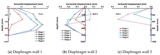
Figure 10.
Horizontal displacement diagrams under the “deep to shallow” excavation sequence.
During the excavation of deep foundation pit A (Phases 1–3), lateral displacements of the retaining structure primarily occurred at the outer wall 1# and the shared wall 2#. The horizontal displacement increased progressively with excavation, with the maximum displacement at each step located above the excavation face. The final maximum displacements were 0.223 mm and 0.218 mm, respectively, both directed toward the interior of Pit A. During this phase, the shared wall 2# tilted toward the deep pit, and its displacement gradually increased, while the displacement of the outer wall 3# of the shallow pit was nearly zero.
During the excavation of shallow foundation pit B (Phases 4–5), the displacement of the shared wall 2# shifted from negative to partially positive values, indicating that the upper part of the wall transitioned from tilting toward the deep pit to tilting toward the shallow pit. This was due to significant soil unloading after the shallow pit excavation, causing wall 2# to incline toward the shallow pit side. For the outer wall 1# of the deep pit, the maximum displacement slightly increased from 0.223 mm to 0.252 mm in Phase 4 but remained relatively stable during subsequent shallow pit excavation. The outer wall 3# of the shallow pit exhibited a “concave” deformation pattern, with a maximum displacement of 0.255 mm.
For the second group with the shallow-to-deep construction sequence, the horizontal displacement curves of diaphragm walls 1# to 3# at each excavation stage, plotted against excavation depth, are shown in Figure 11.
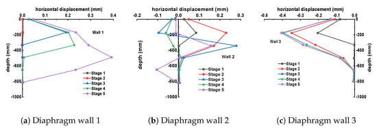
Figure 11.
Horizontal displacement diagrams under the “shallow to deep” excavation sequence.
During the excavation phase of shallow foundation pit B, specifically Stages 1–2, the lateral displacement of the retaining structure primarily occurs at the exterior wall 3# and the shared wall 2# of the shallow foundation pit. As the excavation progresses, the horizontal displacement gradually increases. The maximum horizontal displacement at each excavation step is consistently observed above the excavation face. Both walls 2# and 3# tilt towards the excavation side of the shallow pit, and their maximum horizontal displacements gradually increase to 0.228 mm and 0.351 mm, respectively. The displacement of the exterior wall 1# of the deep pit remains almost unchanged.
During the excavation phase of deep foundation pit A, specifically Stages 3–5, as the deep foundation pit begins to be excavated, the unloading of the soil mass becomes increasingly significant. This causes the horizontal displacement of the shared wall 2# to gradually decrease from its original positive increasing trend, meaning the shared wall tilts towards the deep pit being excavated. The lateral displacement of the exterior wall 1# of the deep pit continues to develop towards deep foundation pit A, with a maximum horizontal displacement of 0.394 mm. When deep foundation pit A is excavated to the same depth as shallow foundation pit B (−500 mm), specifically at the end of Stage 4, the change in the exterior wall 3# of the shallow pit no longer significantly increases, remaining around 0.406 mm.
The construction sequence of the third group of synchronous excavations, the horizontal displacement curves of the diaphragm walls 1# to 3# at each excavation stage, are shown in Figure 12.
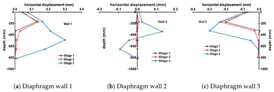
Figure 12.
Horizontal displacement diagrams of walls under synchronous excavation conditions.
As shown in the figure, for the shared wall 2#, during Stages 1 and 2, due to the simultaneous excavation on both sides of the foundation pit and the concurrent unloading of soil on both sides, the horizontal displacement of the diaphragm wall 2# did not exhibit significant changes. In Stage 3, the portion above the excavation face tilted towards the shallow pit, while the portion below the excavation face tilted towards the deep pit due to the unloading of soil on the final side of the deep pit. For the exterior walls 1# and 3#, during the excavation process, their displacements gradually increased, curving inward towards the pit. The point of maximum horizontal displacement shifted downward as the depth increased, reaching final maximum values of 0.299 mm and 0.298 mm, respectively, at the end of the excavation.
3.2. Adjacent Foundation Pit Behavior
The excavation and deformation behaviors of adjacent foundation pits differ significantly from segmented configurations due to their closer proximity and direct mutual influences. This section presents the deformation results from physical model tests conducted under three distinct excavation sequences: small-section first followed by large-section excavation, large-section first followed by small-section excavation, and synchronous excavation. By analyzing the variations in diaphragm wall displacement patterns across these scenarios, this study identifies optimal construction sequencing strategies to mitigate deformation and enhance the stability of retaining structures in adjacent foundation pit groups.
The first group followed the construction sequence of excavating the smaller section first, followed by the larger section. The horizontal displacement of diaphragm walls 1# to 4# at each excavation stage, plotted against excavation depth, is shown in Figure 13.
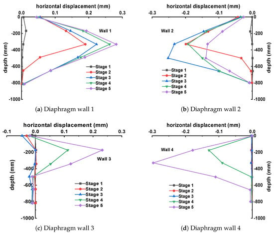
Figure 13.
Horizontal displacement diagrams under the condition of small cross section excavation followed by large cross section excavation.
From the figure, it can be observed that during the excavation of Pit A, the deformation of diaphragm wall 1# is slightly larger than that of diaphragm wall 2# due to the presence of diaphragm wall 3#. During the subsequent excavation of Pit B, the horizontal displacement of retaining wall 1# continues to increase gradually, while that of diaphragm wall 2# further decreases, as shown in Stages 4 and 5 of Figure 13b. The primary reason is that during the excavation of Pit B, the earth pressure acting on diaphragm wall 2# decreases, causing the entire foundation pit to tilt toward the subsequently excavated Pit B. For diaphragm wall 3#, during Stages 1–3, due to the unloading caused by the excavation of Pit A, the soil outside the pit tends to move toward Pit A. In Stages 4–5, with the unloading from the excavation of Pit B, it gradually exhibits a convex deformation toward the interior of Pit B. As for diaphragm wall 4#, due to its relatively distant location, the excavation of Pit A has little impact on its deformation. Its lateral displacement only begins to increase gradually during the excavation of Pit B.
The second group followed the construction sequence of excavating the larger section first, followed by the smaller section. The horizontal displacement of diaphragm walls 1# to 4# at each excavation stage, plotted against excavation depth, is shown in Figure 14.
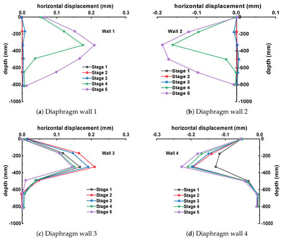
Figure 14.
Horizontal displacement diagrams under the condition of large cross section excavation followed by small cross section excavation.
During the initial excavation of the larger section (Pit B, Stages 1–2), the horizontal displacement of diaphragm walls 1# and 2# in the smaller-section pit remains nearly unchanged due to the presence of the limited-width soil mass between them. The displacement gradually increases during the subsequent excavation of the smaller-section pit. For diaphragm wall 3#, which is located adjacent to the larger-section Pit B, its displacement initially increases during the deep excavation stage. However, it gradually decreases afterward, shifting toward the subsequently excavated pit. Diaphragm wall 4# consistently exhibits negative displacement throughout the process. The deformation trends of the diaphragm walls in this scenario are similar to those observed in the first group. The displacement of each wall first increases and then decreases, with the overall trend inclining toward the interior of the actively excavated pit.
For the third group of synchronous construction sequences, the horizontal displacement curves of diaphragm walls 1# to 4# at each excavation stage, plotted against excavation depth, are shown in Figure 15.
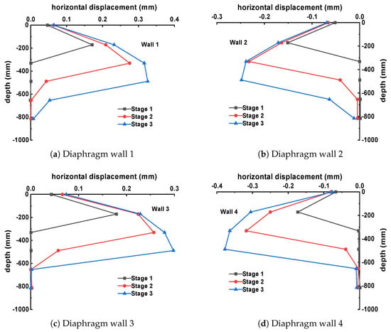
Figure 15.
Horizontal displacement diagrams under synchronous excavation conditions.
The horizontal displacements of each wall gradually increase as synchronous excavation progresses. The points of maximum lateral displacement are all located above the excavation face, with deformations developing inward toward their respective foundation pits. By comparing diaphragm walls 1# and 2# of the smaller-section Pit A with walls 3# and 4# of the larger-section Pit B, it is observed that the maximum horizontal displacements at the end of each excavation stage for walls 1# and 2# are approximately 0.170 mm, 0.275 mm, 0.325 mm and 0.152 mm, 0.245 mm, 0.258 mm, respectively. For walls 3# and 4#, the maximum horizontal displacements at the end of each excavation stage are approximately 0.174 mm, 0.256 mm, 0.296 mm and 0.168 mm, 0.318 mm, 0.379 mm, respectively. From these results, it can be concluded that the deformation of wall 2# is generally smaller than that of wall 1#, and the deformation of wall 3# is generally smaller than that of wall 4#. The reason for this is that walls 1# and 4# are located on the side farther from the adjacent foundation pit, while walls 2# and 3# are on the side closer to the adjacent pit. The presence of a limited-width separation zone between them results in a smaller spacing of adjacent soil and lower earth pressure, leading to relatively smaller deformations in walls 2# and 3#.
3.3. Pit Spacing Parametric Analysis
The following analysis supplements the previous study on the influence of foundation pit spacing during synchronous excavation of adjacent foundation pits. A parametric analysis is conducted to investigate the effect of different pit spacings on the deformation of diaphragm walls. The analysis is performed using PLAXIS 3D software, where a three-dimensional finite element model is established at the same scale as the model tests. The ratios of B/He (spacing between adjacent pits/excavation depth) are set to 0.2, 0.6, 1, and 1.4. Given the excavation depth of 0.6 m in this test, the corresponding separation zone widths are 120 mm, 360 mm, 600 mm, and 840 mm, which serve as reference values, as shown in Figure 16.
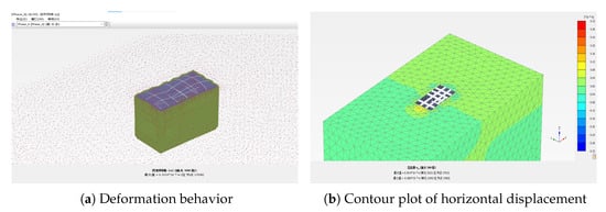
Figure 16.
Model construction.
Table 3 lists the parameter values for sandy soil. To validate the feasibility of the soil parameter selection method, the measured data for diaphragm walls 2# and 3# during synchronous excavation of adjacent foundation pits were analyzed. Simulation results using two parameter sets were compared with measured values, as shown in Figure 17, which presents the horizontal displacements of the retaining structure. The curves demonstrate that the modified HSS constitutive model, incorporating small-strain stiffness characteristics, aligns better with the measured data. Thus, it more accurately simulates the deformation behavior of the retaining structure during excavation. The numerical results also match the experimental deformation trends, confirming the feasibility of the constitutive model.

Table 3.
Values of physical and mechanical parameters for sandy soils.
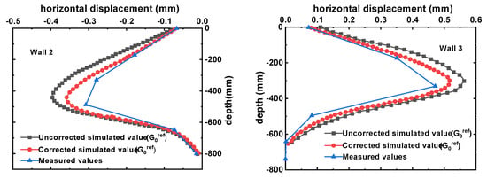
Figure 17.
Comparison of simulated and measured horizontal displacements.
As shown in Figure 18, the earth pressure distribution behind the diaphragm wall under four separation zone widths is presented. The figures indicate that the earth pressure generally decreases as excavation progresses. For larger finite soil widths, the retaining structure experiences greater deformation per soil layer unloading, but the reduction in earth pressure is smaller. For example, at a width-to-depth ratio of 1.4, the earth pressure at the wall toe decreases only from 7.95 kN/m2 to 6.69 kN/m2 by the end of excavation. In contrast, for smaller finite soil widths, the incremental deformation of the diaphragm wall decreases, but the reduction in earth pressure becomes more significant. For instance, at a width-to-depth ratio of 0.2, the earth pressure at the wall toe decreases from 7.05 kN/m2 to 5.5 kN/m2 by the end of excavation.
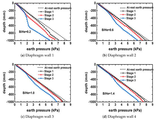
Figure 18.
Horizontal displacement diagrams under synchronous excavation conditions.
From the figures, it can be observed that the distribution of earth pressure after excavation exhibits similar trends under different separation zone widths. The distribution curve shows an inflection point near the excavation face. Above the inflection point, the earth pressure distribution is nonlinear and gradually decreases as excavation progresses. Below the inflection point, the earth pressure on the diaphragm wall follows a linear distribution, with a slope consistent with that of the at-rest earth pressure line. As the foundation pit spacing decreases, the earth pressure curve deviates further from the at-rest earth pressure value. Conversely, as the foundation pit spacing increases, the earth pressure curve approaches the at-rest earth pressure. When the foundation pit spacing exceeds 0.6 times the excavation depth (i.e., B/He > 0.6), the increase in active earth pressure gradually diminishes.
The horizontal displacement curves of the retaining structures for adjacent foundation pits under different width-to-depth ratios (B/He = 0.2, 0.6, 1, and 1.4) are shown in Figure 19. At the excavation depth of −250 mm (Stage 1), the lateral displacement of the diaphragm wall increases with larger foundation pit spacing, but the overall difference is relatively small. As excavation progresses through Stages 2 and 3, the influence of foundation pit spacing on the horizontal displacement of the retaining structures becomes more pronounced. During Stage 2, the maximum deformation of the wall at a width-to-depth ratio of 1.4 is 0.185 mm, while at a width-to-depth ratio of 0.2, it is only 0.117 mm. Similarly, during Stage 3, the maximum deformation at a width-to-depth ratio of 1.4 is 0.417 mm, compared to 0.285 mm at a width-to-depth ratio of 0.2, indicating a more significant variation in this stage.
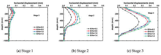
Figure 19.
Active earth pressure on the retaining structure.
These results demonstrate that the foundation pit spacing between adjacent foundation pits has a considerable impact on the deformation of the retaining structures on the adjacent side, but it does not affect the location of the maximum deformation, which remains near the excavation face. For wall top displacement, as the pit spacing increases, the displacement also increases, suggesting that greater attention should be given to controlling the wall top displacement on the adjacent side when the spacing between adjacent foundation pits is larger.
4. Discussion
4.1. Comparison of Segmented Foundation Pit Deformation Under Different Excavation Sequences
The experimental findings on segmented pit deformation align with and extend previous research on excavation sequencing effects. Lin et al. [], studying large-scale zoning excavation in Hangzhou soft soil, similarly emphasized the significant reduction in overall deformation achievable through sectional excavation but highlighted the critical need for sequence optimization to balance support forces. Our results quantitatively demonstrate this optimization: Figure 20 compares the maximum horizontal displacements of the diaphragm walls under the three different construction sequences. The maximum positive displacement of the shared wall 2# occurs under the shallow-to-deep construction sequence, measuring 0.394 mm. For the shared wall 2#, the maximum positive displacement is observed in the shallow-to-deep construction sequence, reaching 0.278 mm. The maximum positive displacement of wall 3# is found in the shallow-to-deep construction sequence, at 0.406 mm. As shown in the figure, compared to the other two construction sequences, the “shallow-to-deep” sequence results in the largest deformation of the retaining walls. In contrast, the “deep-to-shallow” construction method demonstrates some effectiveness in controlling the deformation of the exterior walls (1# and 3#), reducing their maximum horizontal displacements by 0.132 mm and 0.286 mm, respectively, compared to the “shallow-to-deep” condition. Additionally, synchronous excavation, due to the simultaneous unloading of soil on both sides, proves highly beneficial for controlling the deformation of the shared wall 2#. Compared to sequential excavation, the lateral displacements are reduced by 0.178 mm and 0.286 mm, respectively. This suggests that prioritizing deeper section excavation mitigates the impact on the exterior walls of the shallower pit, a strategy less explicitly quantified in previous case studies like those reviewed by Liu et al. []. Additionally, synchronous excavation, due to the simultaneous unloading of soil on both sides, proves highly beneficial for controlling the deformation of the shared wall 2#. Compared to sequential excavation, the lateral displacements are reduced by 0.178 mm and 0.286 mm, respectively. This significant reduction (18–25%) underscores the efficiency of bilateral symmetrical stress relief, a mechanism less emphasized in the existing literature focused primarily on sequential methods.
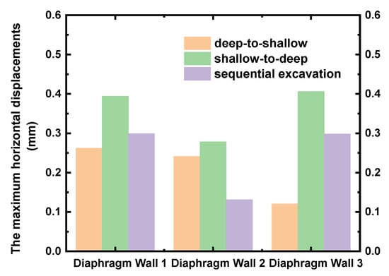
Figure 20.
Comparison of maximum horizontal displacements under different excavation sequences.
The excavation sequence results in varying degrees of deformation in the retaining structure of the foundation pit due to changes in the stress path and stress state of the soil. In the case of “deep-to-shallow” construction sequence, the soil within Pit A initially undergoes vertical unloading caused by the excavation of Pit A, followed by lateral unloading induced by the excavation of Pit B. Conversely, in the case of excavating the shallower section first followed by the deeper section, the soil within Pit A first experiences lateral unloading due to the excavation of Pit B, followed by vertical unloading resulting from the excavation of Pit A. The differing stress paths under these two scenarios lead to distinct developments of plastic deformation in the soil, which in turn modifies soil parameters such as stiffness. Consequently, this results in variations in the deformation of the retaining structure and the ground surface. It is evident that, compared to conventional single-pit excavation, the stress paths in segmented foundation pit excavation are more complex and diverse due to the multiple unloading effects and varying unloading methods. This complexity, highlighted as a research gap in the Introduction, is systematically addressed here through controlled model tests. In conclusion, the construction sequence of excavating the deeper section first followed by the shallower section leads to smaller deformations in the exterior walls of the foundation pit, while the simultaneous excavation sequence is more effective in controlling the deformation of shared walls in segmented foundation pits. This provides actionable guidance beyond the general recommendations for sequence optimization noted by Lin et al. [].
4.2. Comparison of Adjacent Foundation Pit Deformation Under Different Excavation Sequences
The analysis of adjacent pit deformation under different sequences directly addresses the interaction mechanisms [,,]. Yun et al. [] noted mutual influences during synchronous construction of adjacent large deep excavations but lacked detailed quantification of sequential methods. For both sequential and synchronous excavation scenarios, the maximum horizontal displacement of the diaphragm walls on the side adjacent to the neighboring foundation pit decreases due to the reduction in earth pressure between the pits. However, due to the unbalanced forces on both sides of the pits, the entire structures of Pits A and B tilt to accommodate the deformation, resulting in increased deformation of the diaphragm walls on the side farther from the adjacent pit. In the case of sequential excavation, regardless of whether the smaller-section pit is excavated first followed by the larger-section pit or vice versa, the deformation trends of walls 2# and 3# initially tilt toward the first-excavated pit and then toward the subsequently excavated pit. The horizontal displacement alternates between positive and negative directions, subjecting the diaphragm walls to multiple disturbances. This complex tilting behavior and reversal of displacement direction, induced by asymmetric unloading, aligns qualitatively with field observations of adjacent pit interactions []. Therefore, the synchronous excavation method is superior to sequential excavation, reducing maximum wall displacements by 19–32% and effectively minimizing this disruptive multi-directional loading, a significant advantage over sequential methods noted in practice but less rigorously quantified previously.
Further comparing the excavation sequences of “smaller-section first” and “larger-section first”, Table 4 shows that the additional displacements induced by the subsequent excavation of the adjacent pit after the initial excavation of the main pit are as follows: 0.06 mm for wall 1#, 0.118 mm for wall 2#, 0.072 mm for wall 3#, and 0.037 mm for wall 4#. This indicates that the sequence of excavating the larger-section shallow pit first results in relatively smaller displacement and deformation of the diaphragm walls in the main pit. Therefore, when the distance between the pits is within the influence range of excavation, adopting the sequence of excavating the larger-section shallow pit first, followed by the smaller-section deep pit, can reduce the disturbance to the retaining structure of the main pit caused by subsequent excavation.

Table 4.
Maximum horizontal displacements and additional displacements under different excavation sequences.
In summary, this study elucidates the critical impact of adjacent foundation pit spacing on excavation sequence selection through comparative experimental investigations, providing quantitative evidence for strategies previously discussed more qualitatively. Accordingly, the following principles are proposed for engineering practice: (1) Prioritize the simultaneous excavation scheme, which reduces maximum wall displacements by 19–32% compared to sequential excavation methods. (2) When synchronous construction is constrained, adopt the “larger-section-first followed by smaller-section” sequence under limited spacing conditions (specific critical thresholds will be quantitatively addressed in the following subsection). This strategy exploits the pre-deformation of large-section pits to establish isolation zones. (3) For spacing beyond the interaction range, prioritize schedule efficiency and cost-effectiveness in selecting excavation sequences. These findings systematically translate the deformation mechanisms identified in preceding analyses into actionable guidelines for construction methodology optimization.
4.3. The Influence of Foundation Pit Spacing on the Deformation of Retaining Structures
The parametric analysis of pit spacing (B/He) addresses a persistent knowledge gap concerning the quantitative definition of critical spacing thresholds and their governing influence on stress redistribution mechanisms in adjacent pit groups [,]. While prior investigations, such as Huang et al. [], have established correlations between excavation influence zones and depth for adjacent structures, the specific quantification of the B/He ratio as a primary controller of interaction intensity between adjacent excavations remained elusive. Figure 21 shows the relationship between the maximum horizontal displacement of the diaphragm wall and the width-to-depth ratio of the foundation pit. As illustrated in the figure, when the foundation pit spacing is B = 1.0He and B = 1.4He, the increase in the curve becomes more gradual. However, within the range of one times the excavation depth (B ≤ 1.0He), the increase in the curve is more pronounced. This indicates that the horizontal displacement of the retaining structure is significantly influenced by pit spacing within one times the excavation depth. Beyond this range, the influence of spacing on displacement diminishes.
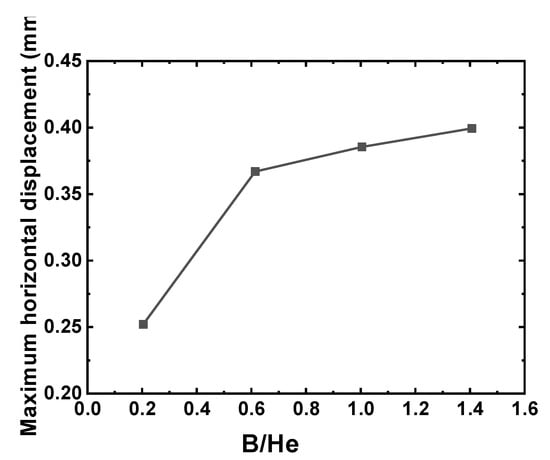
Figure 21.
Influence of pit spacing on the maximum horizontal displacement.
These findings exhibit congruence with the theoretical framework of finite-width soil mechanics applied to earth pressure analysis, wherein inter-pit spacing governs the kinematic interaction potential of active Rankine wedges. The experimental data provide empirical validation that at B/He < 1, pronounced wedge interaction occurs, resulting in synergistic reductions in earth pressure and consequential amplification of retaining wall displacements. Quantitative analysis of earth pressure distributions (Figure 18) further demonstrates that diminished finite soil widths (i.e., lower B/He ratios) induce more substantial earth pressure attenuation at the wall toe—a phenomenon observed despite comparatively smaller incremental displacements per excavation stage. Moreover, the consistent emergence of an inflection point proximal to the excavation face across all B/He cases, coupled with the linearly distributed pressure profile beneath it, conforms to established mechanical principles governing confined soil domains.
This section systematically examines the influence of varying pit spacings (B/He = 0.2–1.4) on the stress–deformation response of retaining structures. The analysis elucidates a critical threshold effect inherent to adjacent pit spacing and establishes its underlying engineering control logic. Armed with the quantitative foundation furnished by these findings—resolving a key knowledge gap previously identified in the field—practical recommendations are formulated: (1) Under spatially constrained site conditions (B/He < 1.0), synchronous excavation schemes warrant prioritization to mitigate adverse interactions. (2) For excavations proximate to sensitive structures, controlling the separation zone width to a minimum of 1.0He is advocated to effectively suppress cumulative displacement effects. This spacing prescription constitutes a concrete, quantitatively derived design criterion, advancing beyond the predominantly qualitative guidance characteristic of prevailing codes and foundational studies. The normalized width–depth ratio (B/He) introduced herein furnishes a robust quantitative framework for the stratified design of adjacent pits within complex geological strata. Furthermore, the elucidated “critical threshold–deformation coupling” mechanism offers direct pathways for the synergistic optimization of economic viability and structural safety in engineering execution. It concurrently establishes a theoretical cornerstone for probing three-dimensional spatial interaction effects in clustered foundation pit construction.
5. Conclusions
This paper conducted indoor physical model tests on two common types of foundation pit configurations in underground space engineering: segmented foundation pits and adjacent foundation pits. The deformation patterns of retaining structures under different construction sequences for adjacent foundation pits were obtained, and parameter analysis was performed using PLAXIS 3D (a three-dimensional finite element analysis software). The main conclusions are as follows:
1. Based on the test results of segmented foundation pit excavation, the synchronous excavation sequence is beneficial for controlling the deformation of the shared diaphragm wall due to simultaneous unloading on both sides. In contrast, sequential excavation, especially the “deep-to-shallow” sequence, results in more complex soil stress paths and smaller deformations of the exterior walls.
2. The test results of adjacent foundation pit excavation show that the deformation of the diaphragm wall on the adjacent side is generally smaller than that on the far side. Synchronous excavation should be prioritized. Under sequential excavation, the overall deformation trend of the diaphragm wall first tilts toward the initially excavated pit and then toward the subsequently excavated pit, causing alternating positive and negative horizontal displacements, which adversely affect the diaphragm wall. The sequence of excavating the larger-section pit first and then the smaller-section pit generates relatively smaller additional displacements for the initially excavated main pit.
3. As the ratio of foundation pit spacing to excavation depth (B/He) increases, the active earth pressure curve approaches the at-rest earth pressure. The active earth pressure curve exhibits an inflection point near the excavation face, with a linear distribution trend below the inflection point. When the pit spacing is less than one times the excavation depth (B/He < 1), the horizontal displacement of the retaining structure is significantly influenced by the foundation pit spacing. When the foundation pit spacing exceeds one times the excavation depth (B/He > 1), the influence of foundation pit spacing on horizontal displacement diminishes.
For future research, we recommend investigating the effects of different soil types and geological conditions on foundation pit deformation and stability. Additionally, expanding the research to more complex foundation pit configurations and developing more advanced numerical models to simulate foundation pit behavior under various construction scenarios would be valuable contributions to the field. Field experiments should also be conducted to further validate the findings from the model tests and numerical simulations presented in this study.
Author Contributions
Conceptualization, Z.Y., R.J., S.G. and Z.C.; Methodology, Z.Y., R.J. and S.G.; Software, Z.Y. and R.J.; Validation, Z.Y., R.J. and Z.C.; Formal analysis, Z.Y., R.J., S.G., Z.C. and G.D.; Investigation, Z.Y., R.J. and G.D.; Resources, Z.Y., R.J., S.G. and G.D.; Data curation, Z.Y. and S.G.; Writing—original draft preparation, Z.Y., R.J., S.G., Z.C. and G.D.; Writing—review and editing, Z.Y., R.J., S.G., Z.C., G.D. and W.Z.; Visualization, Z.Y. and R.J.; Supervision, Z.Y., R.J., S.G., Z.C., G.D. and W.Z.; Project administration, Z.Y. and S.G.; Funding acquisition, S.G., G.D. and W.Z. All authors have read and agreed to the published version of the manuscript.
Funding
This research was funded by the National Natural Science Foundation of China (No. 52378328, 52208333), Research Fund for Advanced Ocean Institute of Southeast University (Key Program KP202404; General Program GP202403).
Institutional Review Board Statement
Not applicable.
Informed Consent Statement
Not applicable.
Data Availability Statement
The original contributions presented in this study are included in the article. Further inquiries can be directed to the corresponding author(s).
Acknowledgments
We thank all those who helped write this article and the editors and reviewers of this paper for their constructive feedback.
Conflicts of Interest
Author Shouye Guan was employed by the company China Railway Construction Investment Group Corporation Limited. The remaining authors declare that the research was conducted in the absence of any commercial or financial relationships that could be construed as a potential conflict of interest.
References
- Wu, W.; Lu, H.; Chen, S.; Zhang, D.; Liu, B. Effect and control of foundation pit excavation on existing tunnels: A state-of-the-art review. Tunn. Undergr. Space Technol. 2024, 147, 105704. [Google Scholar]
- Wei, G.; Feng, F.; Cui, Y.; Wang, X.; Diao, H.; Wu, Y. Research on the influence of foundation pit excavation on the lateral force and deformation of side shield tunnels based on full-scale experiments. Tunn. Undergr. Space Technol. 2023, 140, 105236. [Google Scholar]
- Yang, Y.; Li, X.; Chen, Y. The influence of different excavation methods on deep foundation pit and surrounding environment. In Proceedings of the International Conference on Civil Engineering, Nanchang, China, 4–5 December 2021; Springer: Berlin/Heidelberg, Germany, 2021; pp. 109–129. [Google Scholar]
- Peck, B. Deep excavation and tunnelling in soft ground, State of the art volume. In Proceedings of the 7th ICSMFE, Mexico City, Mexico, 25–29 August 1969; Volume 4, pp. 225–290. [Google Scholar]
- Goldberg, D.T.; Jaworski, W.E.; Gordon, M.D. Lateral Support Systems and Underpinning; Federal Highway Administration, Office of Research & Development: Washington, DC, USA, 1976.
- O’Rourke, T.D. Ground movements caused by braced excavations. J. Geotech. Eng. Div. 1981, 107, 1159–1178. [Google Scholar]
- Long, M. Database for retaining wall and ground movements due to deep excavations. J. Geotech. Geoenviron. Eng. 2001, 127, 203–224. [Google Scholar]
- Niu, P.; Zhou, P.; Jin, C.; Shao, Y. Construction mechanical characteristics and monitoring analysis of the existing subway over the newly built long foundation pit. Buildings 2024, 14, 2385. [Google Scholar] [CrossRef]
- Liu, H.; Li, P.; Liu, J. Numerical investigation of underlying tunnel heave during a new tunnel construction. Tunn. Undergr. Space Technol. 2011, 26, 276–283. [Google Scholar]
- Ma, B.; Wu, S.; Chen, Q.; Liang, E.; Li, X. The influence of existing piles on station settlement during the construction of a tunnel undercrossing under existing stations. Sci. Rep. 2024, 14, 14024. [Google Scholar]
- Huang, J.; Liu, J.; Guo, K.; Wu, C.; Yang, S.; Luo, M.; Lu, Y. Numerical Simulation Study on the Impact of Deep Foundation Pit Excavation on Adjacent Rail Transit Structures—A Case Study. Buildings 2024, 14, 1853. [Google Scholar] [CrossRef]
- Peng, H.; Meng, B.; Tan, S.; Zhu, L.; Wang, G. Study on Deformation Control of Road-Deep Foundation Pit Passing under Elevated Subway Bridge. Appl. Sci. 2024, 14, 6357. [Google Scholar]
- Lin, G.; Lin, Z.; Zhao, Y.; Xu, C.; Sun, F.; Duan, Y.; Fang, T. Force and Deformation Characteristics of Large-Scale Zoning Excavation in Soft Soil: A Case Study in Hangzhou. Appl. Sci. 2024, 14, 6358. [Google Scholar]
- Ge, C.; Yang, M.; Li, P.; Zhang, M. Influence of deep foundation pit excavation on surrounding environment: A case study in Nanjing, China. Acta Geophys. 2025, 73, 495–516. [Google Scholar]
- Pan, P.; Sun, S.H.; Feng, J.X.; Wen, J.T.; Lin, J.R.; Wang, H.S. Intelligent Monitoring System for Deep Foundation Pit Based on Digital Twin. Buildings 2025, 15, 366. [Google Scholar] [CrossRef]
- Yu, J.; Guo, J.; Zhou, J.; Hu, H.; Gong, X. A Simplified Theoretical Method for Estimating the Effect of Capsule Grouting Expansion Technology on Controlling Pile Deformation. Appl. Sci. 2024, 14, 5449. [Google Scholar]
- Peng, H.; Guobin, L.; Runke, H. Parameter Analysis of Partitioned Excavation in Soft Soil Excavations. J. Cent. South Univ. Sci. Technol. 2015, 46, 3859–3864. [Google Scholar]
- Shijin, F.; Guangyun, G.; Hongtao, A.; Weihua, L. Deformation Analysis of Excavation Group Near Metro Tunnels. Chin. J. Geotech. Eng. 2008, 30, 12–117. [Google Scholar]
- Yun, L.; Zhiqing, M.; Zhen, T.; Qianyan, G. Study on the Mutual Influence of Synchronous Construction of Adjacent Large Deep Excavations. Port Waterw. Eng. 2009, 96–100. [Google Scholar] [CrossRef]
- Lo, K.; Ramsay, J. The effect of construction on existing subway tunnels—A case study from Toronto. Tunn. Undergr. Space Technol. 1991, 6, 287–297. [Google Scholar]
- Tan, Y.; Wang, D. Structural behaviors of large underground earth-retaining systems in Shanghai. I: Unpropped circular diaphragm wall. J. Perform. Constr. Facil. 2015, 29, 04014058. [Google Scholar]
- Atkinson, J. Experimental determination of stress-strain-time characteristics in laboratory and-in-situ tests. General report. In Proceedings of the 10th European Conference on Soil Mechanics and Foundation Engineering, Florence, Italy, 26–30 May 1991; Volume 3, pp. 915–956. [Google Scholar]
- Wu, S.H.; Ching, J.; Ou, C.Y. Predicting wall displacements for excavations with cross walls in soft clay. J. Geotech. Geoenviron. Eng. 2013, 139, 914–927. [Google Scholar]
- Liu, G.; Ng, C.W.; Wang, Z. Observed performance of a deep multistrutted excavation in Shanghai soft clays. J. Geotech. Geoenviron. Eng. 2005, 131, 1004–1013. [Google Scholar]
- Tan, Y.; Li, M. Measured performance of a 26 m deep top-down excavation in downtown Shanghai. Can. Geotech. J. 2011, 48, 704–719. [Google Scholar]
- Lee, F.H.; Yong, K.Y.; Quan, K.C.; Chee, K.T. Effect of corners in strutted excavations: Field monitoring and case histories. J. Geotech. Geoenviron. Eng. 1998, 124, 339–349. [Google Scholar]
- Greco, V. Active thrust on retaining walls of narrow backfill width. Comput. Geotech. 2013, 50, 66–78. [Google Scholar]
- Greco, V.R. Analytical solution of seismic pseudo-static active thrust acting on fascia retaining walls. Soil Dyn. Earthq. Eng. 2014, 57, 25–36. [Google Scholar]
- Hu, W.; Zhu, X.; Zeng, Y.; Liu, X.; Peng, C. Active earth pressure against flexible retaining wall for finite soils under the drum deformation mode. Sci. Rep. 2022, 12, 497. [Google Scholar]
- Bang, S. Active earth pressure behind retaining walls. J. Geotech. Eng. 1985, 111, 407–412. [Google Scholar]
- Nakai, T. Finite element computations for active and passive earth pressure problems of retaining wall. Soils Found. 1985, 25, 98–112. [Google Scholar]
- Sun, Y.; Xiao, H. Wall displacement and ground-surface settlement caused by pit-in-pit foundation pit in soft clays. KSCE J. Civ. Eng. 2021, 25, 1262–1275. [Google Scholar]
- Brinkgreve, R.B.J.; Broere, W. Plaxis: 3D Foundation-Version 1; Brinkgreve, R.B.J., Broere, W., Eds.; Balkema: Leiden, The Netherlands, 2004. [Google Scholar]
- Burland, J. Small is beautiful—The stiffness of soils at small strains, Ninth Laurits Bjerrum memorial lecture. Can. Geotech. J. 1989, 26, 499–516. [Google Scholar]
- Jardine, R.; Potts, D.; Fourie, A.; Burland, J. Studies of the influence of non-linear stress–strain characteristics in soil–structure interaction. Geotechnique 1986, 36, 377–396. [Google Scholar]
- Mair, R. Developments in Geotechnical Engineering Research: Application to Tunnels and Deep Excavations. 1993, pp. 27–41. Available online: https://scispace.com/papers/developments-in-geotechnical-engineering-research-2ybosnxn7y (accessed on 1 February 2025).
- Xiaoqiang, G.; Ruituo, W.; Fayun, L.; Guangyun, G. Parameter Determination Method and Engineering Verification of the Small Strain Hardening Model for Shanghai Soil. Rock Soil Mech. 2021, 42, 833–845. [Google Scholar] [CrossRef]
- Liu, Q.; Jiang, H.; Tao, G.; Zhuge, P. Experimental and Theoretical Study on Anchorage Loss of Prestressed CFRP-Reinforced Concrete Beams. Appl. Sci. 2024, 14, 6246. [Google Scholar]
Disclaimer/Publisher’s Note: The statements, opinions and data contained in all publications are solely those of the individual author(s) and contributor(s) and not of MDPI and/or the editor(s). MDPI and/or the editor(s) disclaim responsibility for any injury to people or property resulting from any ideas, methods, instructions or products referred to in the content. |
© 2025 by the authors. Licensee MDPI, Basel, Switzerland. This article is an open access article distributed under the terms and conditions of the Creative Commons Attribution (CC BY) license (https://creativecommons.org/licenses/by/4.0/).