1. Introduction
With the rapid advancement of visual perception technologies such as video surveillance, intelligent transportation, and autonomous driving, wide-angle and fisheye cameras have been widely adopted in complex real-world scenarios due to their superior field-of-view coverage and efficient information acquisition capabilities [
1,
2]. However, these lenses often introduce severe geometric distortions during image acquisition, manifesting as edge stretching, radial deformation, and structural warping [
3]. Such distortions not only compromise geometric consistency but also severely affect the accuracy and robustness of downstream tasks, including image analysis, object recognition, and multi-view image stitching [
4,
5]. Therefore, developing methods for accurate distortion rectification and seamless image stitching, with minimal loss of visual integrity, remains a key challenge in the field of computer vision.
Although deep learning-based approaches have achieved notable progress in image rectification tasks in recent years [
6,
7], most state-of-the-art models rely on large-scale networks and high-performance computing resources, making them unsuitable for deployment in resource-constrained environments where low latency and real-time performance are critical [
8]. These models often perform poorly on edge platforms such as smart surveillance systems and mobile sensing devices. Meanwhile, traditional image rectification and stitching methods are primarily based on geometric modeling—such as polynomial distortion correction and homography transformations [
9,
10]—which, despite their adaptability in specific scenarios, lack generalizability and robustness when applied to high-resolution images, non-rigid deformations, or dynamic scenes [
11]. Furthermore, multi-camera stitching tasks face additional system-level challenges such as image synchronization, dynamic seam-line adjustment, frame rate control, and resource allocation [
12], posing significant trade-offs between lightweight design, high performance, and deployment feasibility.
In response to the aforementioned challenges, this study proposes an image processing framework that achieves both high-precision distortion correction and efficient deployment on edge devices. At the algorithmic level, a lightweight image rectification network is designed, integrating a Swin Transformer-based encoder architecture, a Thin Plate Spline (TPS) control point prediction module, and an optical flow estimation mechanism [
13,
14,
15]. The network enhances feature representation through a sliding window attention mechanism and multi-scale feature extraction modules while leveraging optical flow vector directions as structural constraints to effectively model nonlinear distortions, thereby improving rectification accuracy and robustness. To further enhance generalization performance, the framework incorporates a comprehensive data augmentation strategy—including random cropping, elastic deformation, illumination simulation, and noise injection [
16]—as well as a spatial attention module (SAM) and multi-branch feature fusion [
17], enabling the model to better adapt to complex scene variations.
At the system engineering level, a real-time dual-camera image stitching system is implemented on the Jetson TX2 NX edge computing platform. Leveraging CUDA-based parallel computation and the DeepStream multimedia framework, the system realizes an end-to-end pipeline encompassing image acquisition, preprocessing, rectification, stitching, and video streaming [
18,
19]. In addition, structural optimizations are applied to reduce computational complexity—such as resizing and pruning Swin Transformer layers, simplifying the TPS prediction module, and employing low-rank approximation and network pruning techniques [
20]—thereby ensuring that the proposed model satisfies the dual requirements of real-time performance and deployment stability in resource-constrained environments.
The main objectives of this study can be summarized as follows:
- (1)
To develop a deep rectification network tailored for high-resolution wide-angle images that balances accuracy, speed, and deployment feasibility;
- (2)
To implement a dual-camera stitching system that integrates image preprocessing, registration, and GPU-based stitching, enabling real-time image fusion and visual output;
- (3)
To achieve a closed-loop transition from algorithm design to deployment on edge devices, ensuring efficient system operation and engineering maintainability under resource-constrained conditions.
Taken together, this work provides a comprehensive technical pathway encompassing lightweight algorithm design, system-level integration, and embedded platform deployment, thereby facilitating the transformation of wide-angle image processing technologies from theoretical research to practical engineering applications. The proposed approach holds significant theoretical and practical value for the real-time implementation and productization of intelligent vision systems.
3. Methodology
3.1. Network Architecture Design and Optimization
The image correction algorithm proposed in this study is built upon an encoder–decoder architecture based on the Swin Transformer [
43], which integrates shifted window attention with multi-scale feature extraction to effectively balance correction performance and computational efficiency.
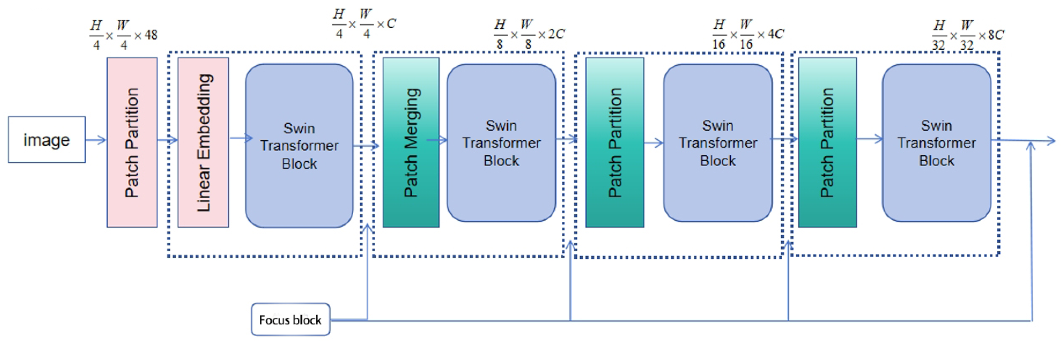
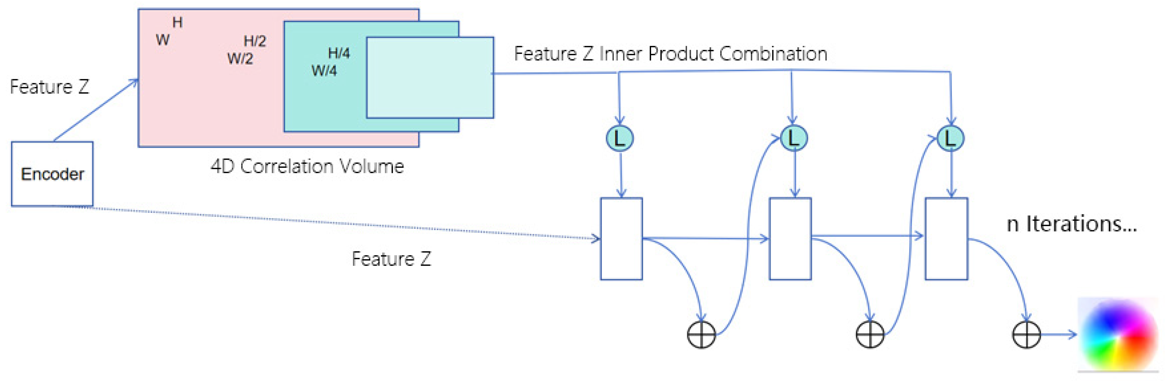
The input image is first decomposed into multiple resolution levels, and the extracted multi-scale features are fed into the TPS control point prediction module to generate a deformation control map. This map is subsequently passed through the decoder to produce the motion estimation flow. In parallel, the features are also input into the optical flow estimation module, which assists in deformation modeling and guides the overall loss optimization process. The complete network architecture is illustrated in
Figure 1.
To enhance the correction accuracy and generalization capability of the model for high-resolution distorted images, this study incorporates three multi-scale enhancement strategies into the network architecture.
First, during the training phase, in addition to using standard public datasets, image region masks are introduced to emphasize dominant content areas. These masks guide the network to focus on key regions, thereby improving feature weighting and enhancing the model’s perceptual sensitivity to geometrically critical zones.
Second, the backbone employs a Swin Transformer with a shifted window encoding structure, which divides the input image into patches and maps them into a high-dimensional semantic space. Combined with downsampling operations, this design increases channel dimensionality while reducing spatial resolution, effectively improving local feature representation.
Third, multi-scale focus modules are embedded between successive Swin Transformer blocks. These modules integrate dilated convolutions and dual skip connections to expand the receptive field, enabling the joint modeling of local details and global contextual information. This structure significantly improves the model’s adaptability to complex and irregular distortions.
The multi-scale features extracted from the encoder are then fed into the TPS control point prediction module, where a set of convolutional kernels—guided by optical flow vectors—iteratively model non-rigid deformations to produce progressively refined control point maps. These maps are subsequently passed to the decoder to generate the motion estimation flow. In parallel, the original image features are processed by the optical flow estimation module, which employs a feature correlation layer and a GRU-based recurrent mechanism to output the final dense flow field. Both motion representations are fused via concatenation and jointly optimized using a unified loss function.
Given the structural complexity and inference latency of conventional Transformer-based networks in high-resolution wide-angle image processing, a lightweight redesign of the Swin architecture is further implemented. This includes reducing the number of encoder/decoder layers, pruning redundant modules, decreasing the number of attention heads, and simplifying parameter-intensive components. These modifications significantly reduce computational overhead.
Experimental results confirm that the optimized model maintains competitive correction performance while substantially improving inference speed, demonstrating strong potential for deployment in edge computing environments and real-world applications.
3.2. Multi-Scale Feature Extraction Module
3.2.1. Encoder Architecture for Multi-Scale Feature Extraction
The shifted window attention mechanism in the Swin Transformer enables efficient extraction of multi-dimensional image features within local spatial regions and serves as the core foundation for feature representation in this study. To further enhance the expressive capacity of the network, two types of multi-scale feature enhancement modules are introduced between the sliding window attention layers: the Cross-Scale Enhancement and Dilated (CED) Block and the Intermediate Focus Block. Specifically, the CED Block extracts features from multiple resolution scales within the same image, effectively improving the model’s horizontal multi-scale perceptual capacity. In contrast, the Intermediate Focus Block increases network depth to capture richer semantic hierarchies from a vertical dimension, thereby significantly strengthening the model’s understanding of global contextual information.
The proposed encoder architecture consists of four main stages, with the first three stages composed of repeated stacks of sliding window attention modules. These layers progressively extract hierarchical structural features from the input image, forming a gradual feature abstraction process. The complete structure of the encoder is illustrated in
Figure 2.
In this study, the encoder architecture begins with a patch partitioning layer that divides the input image into fixed-size patches, with a default size of 4 × 4 pixels per patch. This operation results in a downsampling along each spatial dimension and increases the number of output channels by a factor of 16 (i.e., 42), significantly enhancing the feature representation capacity while maintaining computational efficiency. This patch partitioning mechanism is similar to the Patch Embedding used in Vision Transformer (ViT), but the proposed method adopts smaller patch sizes to better capture fine-grained local features.
Following the patch partitioning, a linear embedding layer projects each low-dimensional feature vector into a predefined high-dimensional space of size , which serves as the input for the subsequent self-attention mechanisms. The dimensionality is determined based on a trade-off between model capacity and computational cost, with the goal of achieving an optimal balance between expressive power and resource efficiency.
Within the hierarchical structure of the encoder, the Patch Merging module is used to merge each group of 2 × 2 adjacent image patches into a new structural block, thereby performing spatial downsampling. This process not only reduces the spatial resolution of the feature maps but also reorganizes the feature dimensions by increasing the number of channels, resulting in more compact inputs with higher semantic density. The aggregation of local region information effectively expands the model’s receptive field and enhances its ability to model contextual relationships.
In addition, the multi-scale feature merging strategy helps capture semantic information across different spatial hierarchies, improving the diversity and generalizability of feature representations. The merged structural blocks are further processed by convolutional layers to enhance the features and extract higher-level abstract semantics.
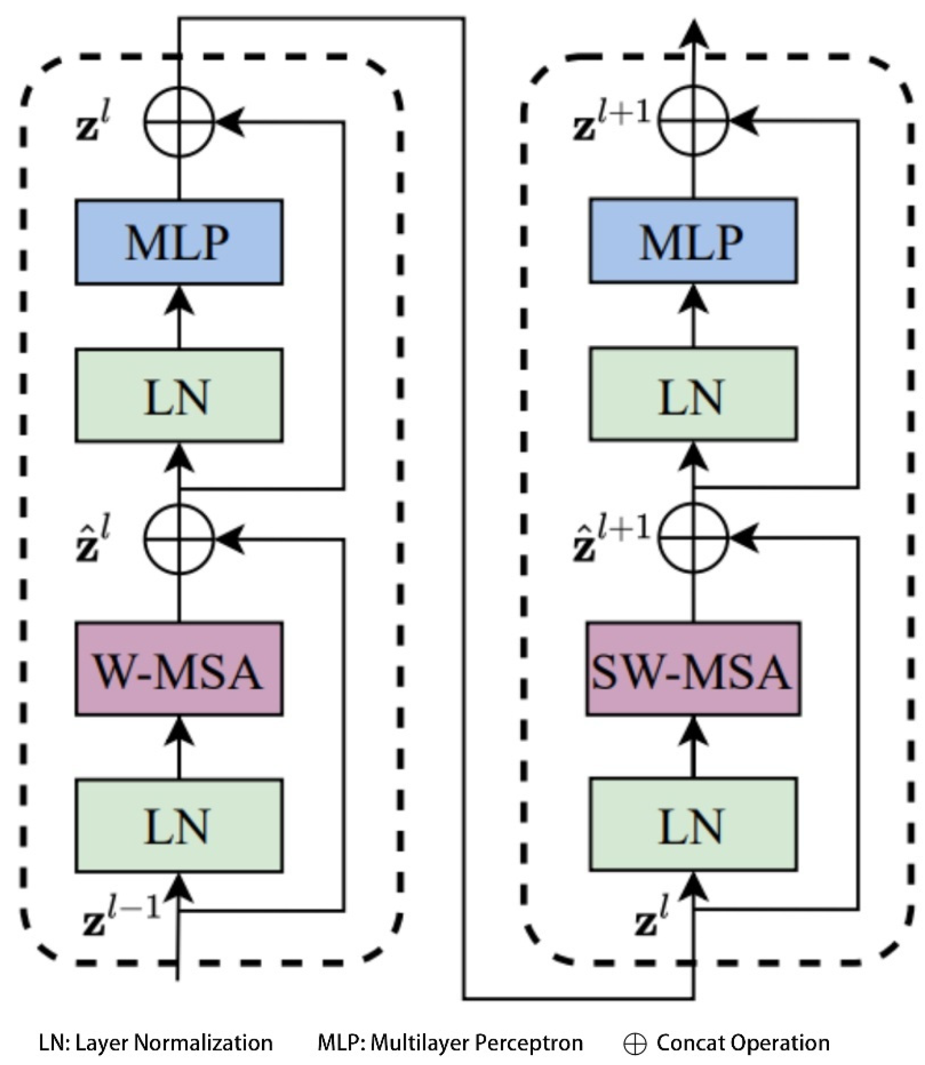
In the core module of the Swin Transformer—namely, the Swin Transformer Block—this study introduces two efficient local attention mechanisms: Window-based Multi-Head Self-Attention (W-MSA) and Shifted Window-based Multi-Head Self-Attention (SW-MSA), which are employed to replace the traditional global Multi-Head Self-Attention (MSA) mechanism [
43]. Compared with global MSA, the sliding window-based attention significantly reduces computational complexity, which can be theoretically expressed as shown in Equation (1).
Here,
and
denote the height and width of the feature map,
represents the number of channels, and
is the window size. For instance, when the feature map size is set to
, the window size
, and the channel dimension
, the W-MSA module can save approximately 40,124,743,680 floating point operations (FLOPs) compared to the conventional global MSA module under the same configuration. This substantial reduction in computational cost significantly improves the inference efficiency of the network. The structure of the Swin Transformer Block is illustrated in
Figure 3.
3.2.2. Design of the Focus Block
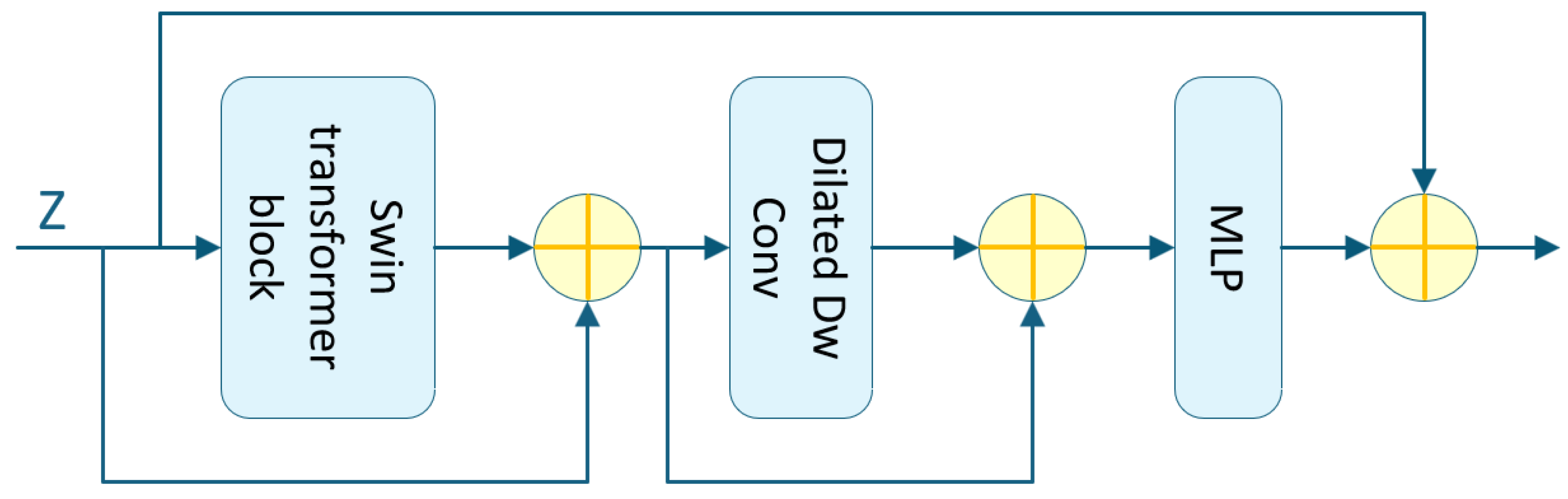
Another key component of the multi-scale feature extraction module is the introduction of the Focus Block, which primarily aims to increase network depth and extract higher-level semantic features from images. This module consists of two core substructures: (1) a Token Mixer responsible for spatial feature interaction and (2) a two-stage Multi-Layer Perceptron (MLP) unit designed to model semantic relationships across channels.
When the Focus Block is positioned between the encoder output and the TPS prediction module input, multiple skip connections are introduced within the block to facilitate direct cross-layer information transmission and integration. This structure helps alleviate the vanishing gradient problem in deep networks and improves both the fidelity and robustness of the extracted features.
The architecture of the Focus Block is illustrated in
Figure 4, where dashed lines indicate skip connection paths between different layers.
3.3. Thin Plate Spline Control Point Prediction Module
TPS transformation is a non-rigid deformation method based on control point interpolation. It achieves locally continuous transformation and fine-grained adjustment of the image while preserving global affine properties by minimizing the bending energy functional quantitative measure of deformation smoothness.
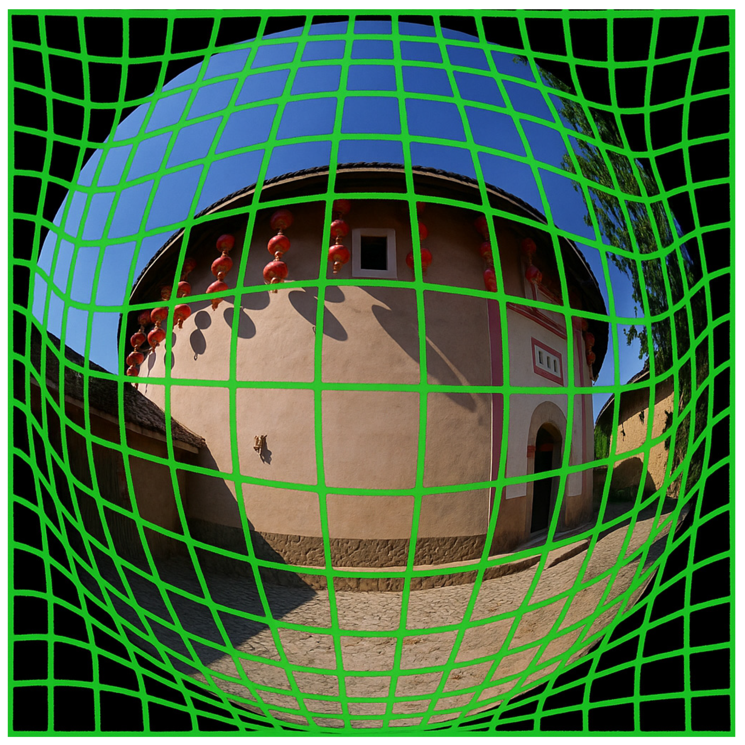
In this study, the image features extracted by the encoder are fed into the TPS prediction module to estimate the spatial distribution of TPS control points. It is important to note that the generation of control points is constrained to the regions defined by the input image mask, allowing the model to focus on areas exhibiting prominent distortions or structural variations. The module outputs the total number of TPS control points across the entire image, which serves as an indicator of local deformation complexity—where a higher number of control points suggests a more complex nonlinear rectification requirement.
This module provides critical support for the subsequent geometric reconstruction of the image and enables accurate spatial transformation and distortion correction.
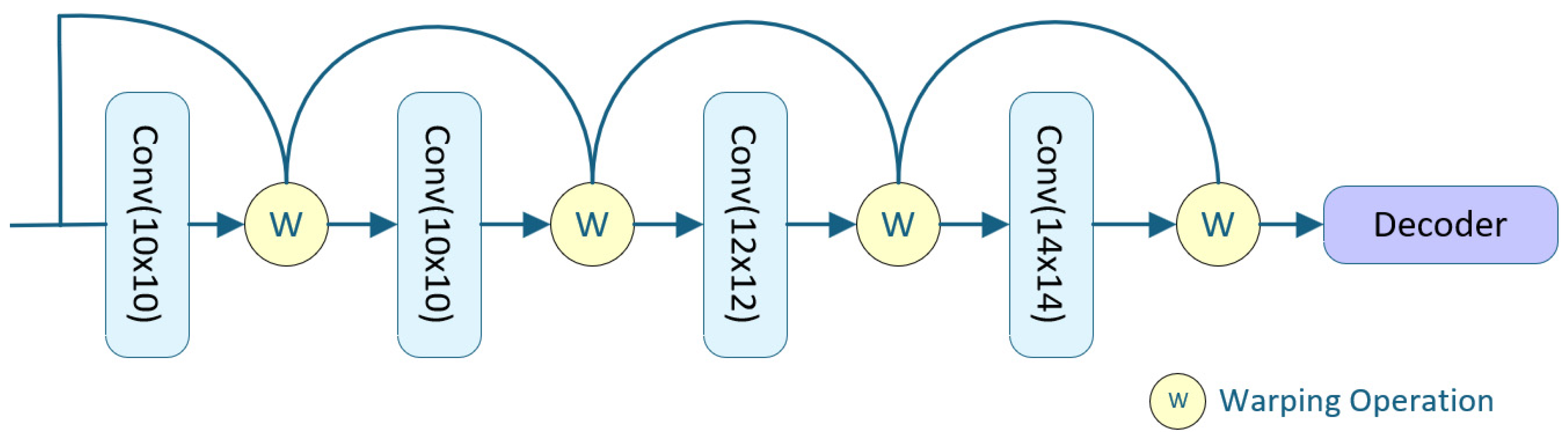
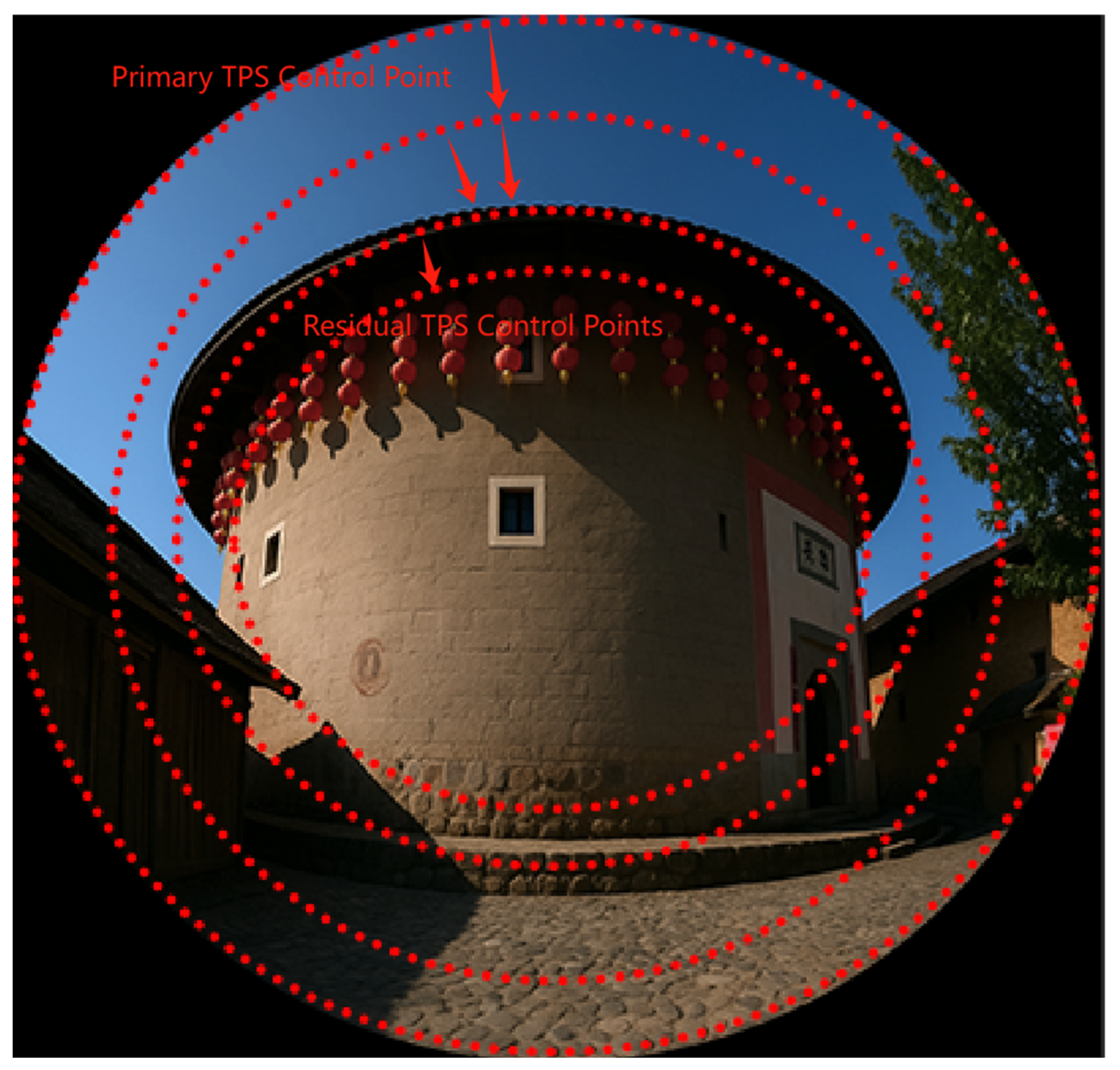
Design of the Thin Plate Spline Control Point Prediction Module
In the TPS control point prediction module, a series of convolutional layers with different kernel configurations are employed to progressively predict an increasing number of control points, progressively configured as 10 × 10, 10 × 10, 12 × 12, and 14 × 14. The number of TPS control points increases at each stage. The control points predicted by the previous head are upsampled and integrated into the next head’s prediction. These control points are then arranged to form a grid structure.
Subsequently, a TPS transformation is applied to warp this predicted grid, aligning it with a reference grid defined on the ground-truth image. The architecture of the TPS control point prediction module is illustrated in
Figure 5.
In implementation, considering that cascading fully connected layers incurs substantial computational and storage costs, we employ one or two convolutional layers after each TPS transformation head to predict the control points. The control point computation is defined by Equation (2).
Here, denotes the TPS transformation at layer t, while and represent the feature map and control points from the ()-th head, respectively. The operator denotes the warping operation applied to the feature map based on the predicted control points, and refers to a custom upsampling layer for control points.
After generating the control point map, it is passed to the decoder, which transforms the feature vectors associated with the TPS control points into the target output sequence. This produces the motion estimation flow, which is then used for loss computation. The output control point map generated by the decoder is illustrated in
Figure 6.
3.4. Optical Flow Estimation Module
The introduction of optical flow fields in this study is inspired by prior work in dynamic scene analysis, where inter-frame optical flow is used to predict the contours and positions of moving objects. In the context of wide-angle image rectification, the positional changes of feature points during the deformation process resemble the motion of dynamic targets. During network training, there exists a progressive transformation process in which normal images are increasingly warped into distorted wide-angle images, and optical flow fields can be computed between these stages.
In this study, we first compute the optical flow between source and target images in the dataset and compare it with the intermediate optical flow fields generated during training. These optical flow fields are incorporated into the loss function to guide the rectification process. The vector directions encoded in the optical flow are used as constraints on image deformation, which not only accelerate network convergence but also enhance the final rectification performance.
3.4.1. Design of the Optical Flow Estimation Module
The design of the optical flow field model in this study is inspired by the classical RAFT architecture [
29] but differs significantly in how image features are handled. Unlike RAFT, where features are extracted independently, the image features in our method are derived directly from the encoder output.
These encoded features are passed into a feature correlation layer, which computes a four-dimensional (4D) correlation volume of size , representing the similarity between all pairs of pixels in the source and target features. This 4D correlation volume is constructed by computing the dot product between every pair of feature vectors.
To improve efficiency and enable scale-aware matching, multi-scale pooling is applied along the last two dimensions of the 4D volume to construct a hierarchy of multi-scale correlation volumes. The 4D volume
can be efficiently computed as a single matrix multiplication, as defined in Equation (3).
The constructed 4D correlation volume is fed into a recurrent GRU-based update module, which iteratively generates the final optical flow field. The flow estimation process is initialized with a zero-flow field, , and a series of flow predictions are progressively refined through iteration. At each iteration step, the update operator computes a flow increment , which is added to the previous estimate to obtain the updated flow field: .
The inputs to the update operator include the current optical flow estimate, the 4D correlation volume, and a latent hidden state. Its output consists of the updated flow increment and a new hidden state. The design of this structure is inspired by the iterative optimization processes commonly found in traditional numerical solvers, aiming to emulate convergence behavior. To this end, the update operator employs parameter sharing (i.e., tied weights) and bounded activation functions to enhance convergence stability during training, ensuring that the predicted optical flow satisfies the convergence condition .
The core architecture of the update operator is based on a Gated Recurrent Unit (GRU), where the fully connected layers are replaced with convolutional layers to enhance local spatial awareness. This modification enables more effective processing of spatial features. The specific computation process is defined in Equation (4).
In this structure, and represent the update gate and reset gate of the GRU, respectively, both computed from feature maps using two distinct convolutional kernels. The convolution operations within the GRU are implemented via learnable kernels and the nonlinear activation function used is . The current hidden state and the previous state encode the temporal dynamics of the optical flow estimation process. The input is formed by concatenating the initial flow estimate, the 4D correlation information, and the context features.
To enlarge the receptive field without significantly increasing model complexity, this study replaces the traditional 3 × 3 convolution with two directionally separable GRUs: one utilizing a 1 × 5 convolutional kernel to capture horizontal context and the other using a 5 × 1 kernel to extract vertical contextual information.
The hidden state output from the GRU module is subsequently passed through two convolutional layers to produce the optical flow update
. To reduce computational cost, the resolution of the predicted flow is set to 1/8 of the input image size. During both training and evaluation, the predicted optical flow is upsampled to match the resolution of the ground-truth flow, enabling accurate supervision and performance assessment. The overall structure of the optical flow estimation module is illustrated in
Figure 7.
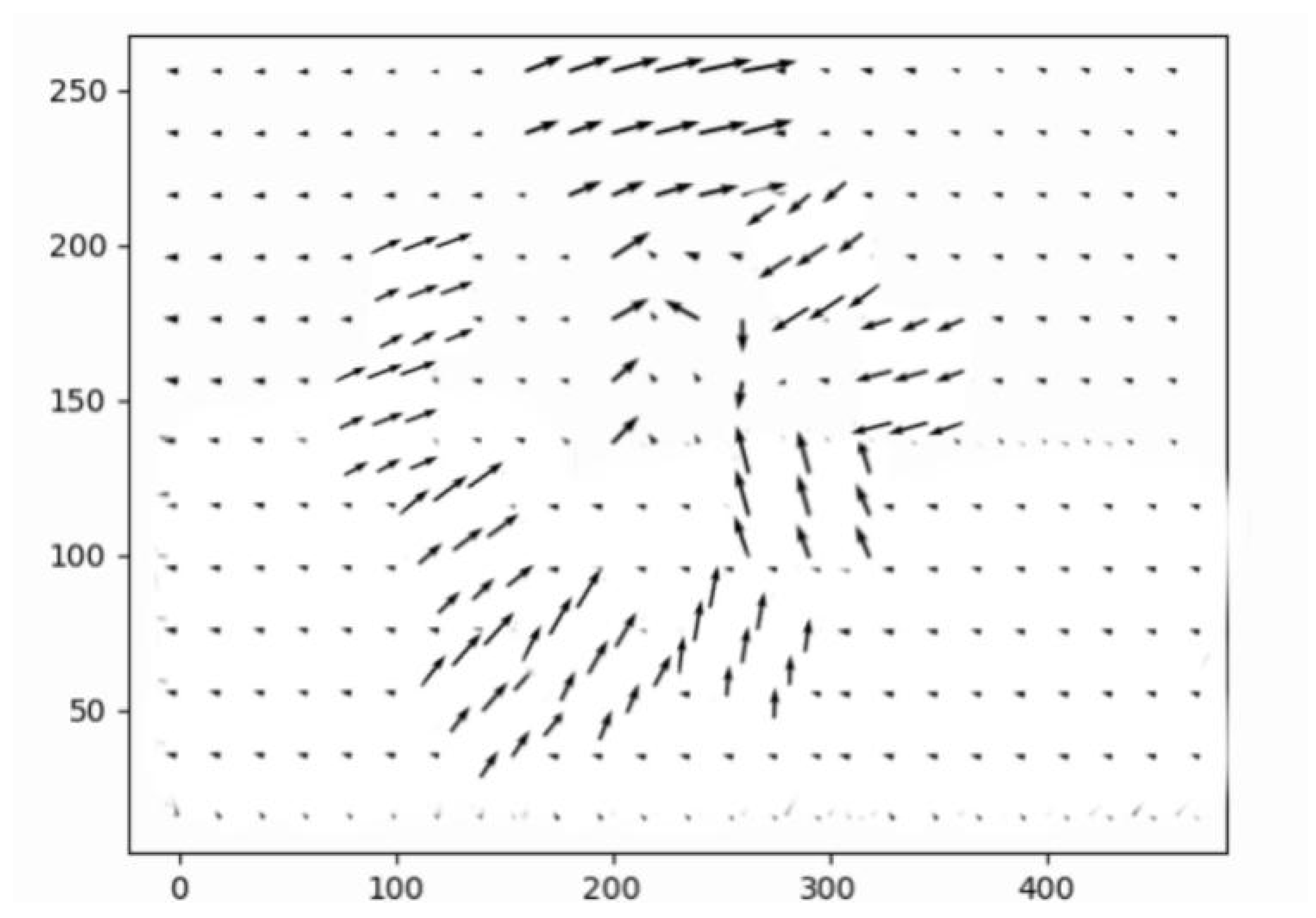
3.4.2. Vector Direction of the Optical Flow Field
After the optical flow field is obtained through iterative updates based on multi-scale image features, the vector direction of the flow field is computed. During network training, this directional information is used to partially update the correction parameters in the TPS prediction module. The optical flow vectors are further combined with the motion estimation flow to perform distortion rectification, and their consistency with the ground-truth image is enforced via loss computation. The full training procedure is detailed in
Section 3.5.
The output rectified maps from each convolutional stage of the TPS prediction module, together with the target image, are used to generate the optical flow field visualization shown in
Figure 8,
Figure 9 and
Figure 10.
3.5. Loss Function
The wide-angle image correction network is designed to train a control point prediction structure based on TPS, which encodes the positions of TPS control points and their corresponding feature point transformations through a multi-scale feature extraction mechanism. Under the guidance of the vector direction of the optical flow field, the network quantifies the degree of feature map distortion and minimizes it during training.
In this study, four loss functions are jointly incorporated to optimize the training process: pixel-wise reconstruction loss (), perceptual loss (), grid regularization loss (), and optical flow constraint loss (). Among them, the reconstruction and perceptual losses supervise the correction process at both the pixel and semantic levels, guiding the network to maintain structural consistency while improving perceptual quality.
The reconstruction loss aims to penalize discrepancies between the output image and the original reference image, ensuring that the generated image remains as close as possible to the target in pixel space. This loss is typically measured using Mean Squared Error (MSE) or Mean Absolute Error (MAE). In this study, MSE is adopted as the primary metric for reconstruction loss, defined as Equation (5):
where
denotes the total number of pixels,
represents the pixel value of the ground-truth image, and
is the corresponding pixel value in the generated image.
The perceptual loss provides supervision from the semantic level. In this study, a VGG-16 network pretrained on ImageNet is adopted as the feature extractor. Intermediate feature representations from both the input and target images are extracted from the ReLU3_3 layer, and their Euclidean distance is computed as the perceptual loss term. This formulation enhances the quality of structural restoration and semantic consistency. The loss is defined as Equation (6):
denotes the intermediate features extracted from the VGG-16 network.
The perceptual loss is typically computed by passing both the input (rectified) image and the target image through a pretrained neural network to obtain their intermediate feature representations. These feature maps are then used as inputs to the loss function, where the distance between them is calculated using either the Euclidean distance (L2 norm) or the Manhattan distance (L1 norm), thereby promoting semantic alignment between the predicted output and the ground truth.
The grid loss constrains the alignment between adjacent deformed grid edges. In Equation (7),
denotes the number of edge tuples in grid
. By maximizing the cosine similarity between adjacent edges, the corresponding edge pairs tend to become collinear. As a result, the loss reaches its minimum, ensuring structural consistency in the corrected image.
Here, the vectors and represent the edges of all consecutively deformed mesh grids in the feature map.
The optical flow distance loss
is calculated using Equation (8) as the L1 distance between the predicted and ground-truth optical flows, with an exponentially increasing weighting scheme applied to emphasize regions with larger motion. Given the ground-truth motion flow field
, the loss is defined as follows:
To enhance training flexibility and balance the contribution of each loss component to the overall optimization objective, this study introduces weight coefficients into the loss formulation, incorporating four distinct terms: reconstruction loss (
), perceptual loss (
), grid regularization loss (
), and optical flow-guided loss (
). The weighted total loss function is constructed as shown in Equation (9), where
to
, respectively, control the relative importance of each loss component:
During the initial training phase, we explored various combinations of loss weights. The results indicated that moderately increasing the weight of the optical flow-guided loss (λ4) helped enhance deformation guidance and improve image reconstruction quality. However, assigning excessive weights to the perceptual loss or grid regularization loss tended to cause training instability or gradient oscillations.
To achieve a balance among training stability, structural accuracy, and generalization capability, we ultimately adopted an equal-weight configuration: . This setting demonstrated consistently good convergence and robustness across multiple validation experiments. Compared to certain weighted configurations that led to unstable training dynamics, the equal-weight strategy exhibited greater stability and controllability in practical deployment, making it a suitable and engineering-friendly choice.
3.6. Accelerated Deployment of the Wide-Angle Image Correction Network
To improve the runtime efficiency of wide-angle image rectification tasks, this study adopts a lightweight Swin-T (Tiny) configuration as the backbone encoder, incorporating multi-scale feature extraction and a shifted window attention mechanism. This design significantly reduces model complexity and computational overhead while maintaining correction accuracy, thereby improving inference speed and promoting structural compactness.
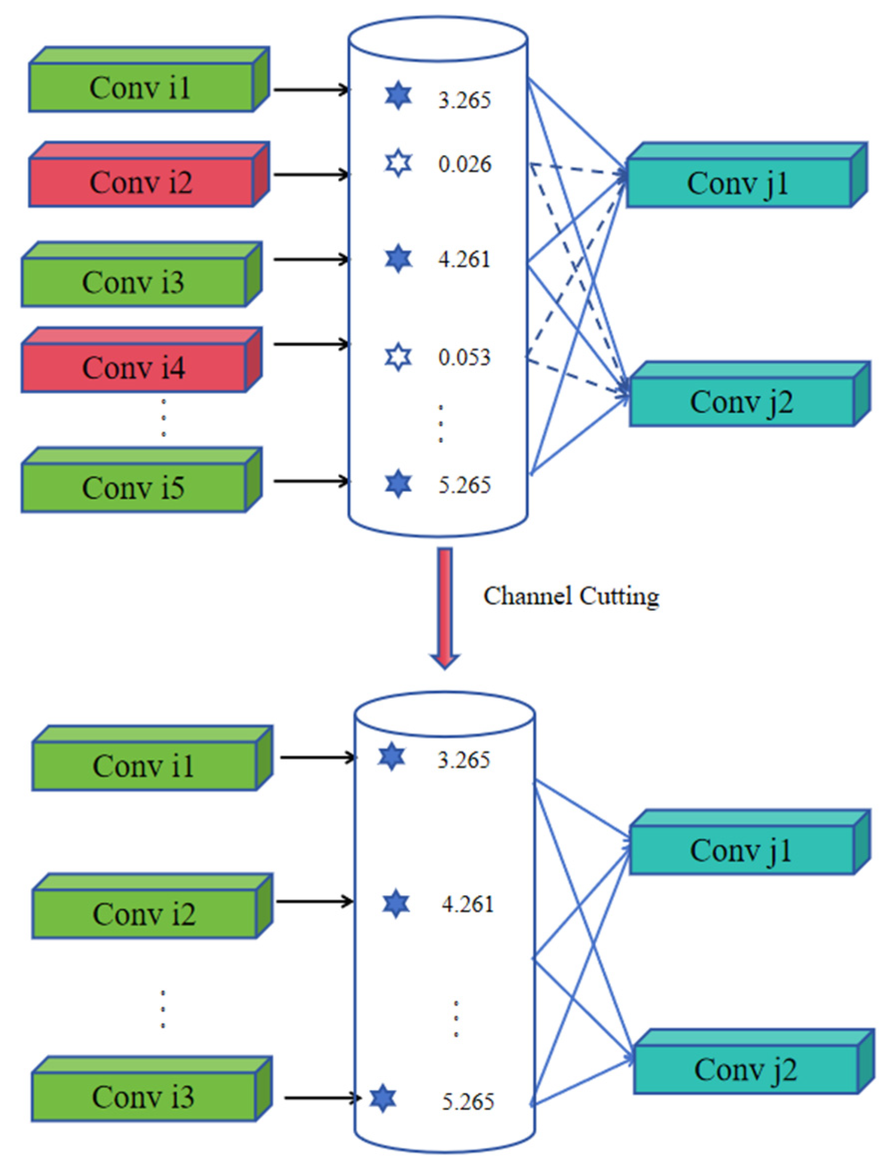
Although the proposed structure achieves satisfactory performance on server-side platforms, its deployment on edge devices such as the Jetson TX2 NX remains constrained by limited computational resources. Specifically, the model exhibits an average inference latency of approximately 150 ms and high GPU occupancy, which does not satisfy the real-time requirement of 15 FPS. To address this limitation, we propose a pruning-based optimization strategy tailored for embedded deployment scenarios, aiming to further reduce the model size and enhance inference efficiency.
More specifically, structural pruning is applied to both the shifted window attention module within the Swin-T encoder and the TPS control point prediction module. The pruning procedure involves the following steps: (1) introducing L1 regularization during retraining to promote sparse weight distributions, thereby identifying redundant channels and attention heads; (2) ranking the importance of hidden channels and attention heads based on their L1 norm values or output contributions; and (3) removing low-contribution structural units to reduce model complexity while preserving inference capability. The overall pruning framework is illustrated in
Figure 11. The performance of the proposed strategy on embedded platforms is further detailed in
Section 4.4.2.
Specifically, to optimize the sliding window attention modules within the encoder, this study introduces an L1 regularization term into the objective function, which promotes sparse weight learning during training. Given an input image resolution of 320 × 320, the original encoder produces a 100 × 100 × 24 feature map. Through pruning, the number of output channels is reduced to 15–20, significantly decreasing computational redundancy.
For the TPS control point prediction module, a flow-guided structural constraint is applied by incorporating the loss term from the optical flow estimation module into the overall objective function. Based on a 320 × 320 × 14 control point map, the pruning process computes the L1 distance between the predicted TPS gradients and the optical flow vector directions, which enables the identification and removal of low-response channels. As a result, the number of output channels is reduced to approximately seven.
The joint pruning optimization of these two modules results in an approximate 40% reduction in total network parameters, thereby substantially enhancing runtime efficiency on embedded platforms.
Regarding weight importance evaluation, channel pruning is implemented by computing the L1 norm across columns (or rows) of convolutional weight matrices, whereas attention head pruning is achieved by aggregating the L1 norms of the
projection matrices within each attention head, as defined in Equations (10) and (11).
Here,
denotes the index of the output channel, and the weight matrix has a shape of
. The L1 norm is computed along the output channel dimension.
Here,
denotes the index of the attention head, and the shape of each attention head’s
projection matrix is
.
L1 regularization promotes sparsity by adding the sum of the absolute values of the weight parameters to the loss function, encouraging some weights to approach zero. The formulation is given in Equation (12).
3.7. Hardware and Software Environment
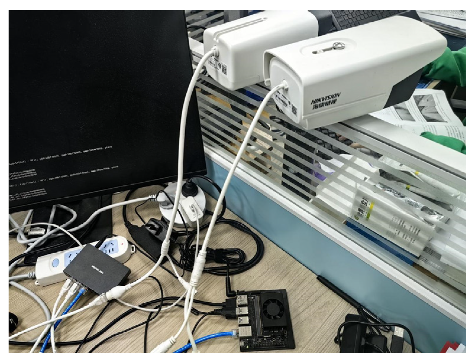
The system is deployed on the Jetson TX2 NX edge computing platform, which features an embedded GPU with 256 CUDA cores (1.33 TFLOPS), supports up to five CSI camera inputs, and is equipped with 4 GB of LPDDR4 memory and a dedicated video codec unit. This hardware configuration makes it well-suited for real-time image correction and stitching tasks. The software environment is built on Ubuntu 18.04 and JetPack 4.5.1, ensuring driver compatibility and system stability.
Two Hikvision B14HV3-LT4MM network cameras (Hikvision, Hangzhou, China), each with a resolution of 2560 × 1440 and a frame rate of 50 Hz, are connected to the system. These cameras support TCP/IP and RTSP protocols and are controlled via the official API. A gigabit router and wired Ethernet connections are used for network communication, enabling high-throughput and concurrent video data transmission (see
Figure 12).
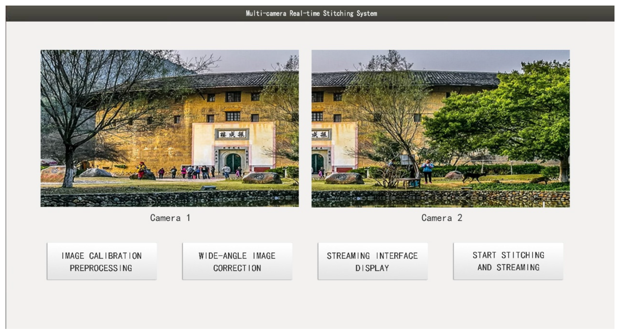
The graphical user interface (GUI) is developed using the Qt framework and supports key functionalities such as dual-camera image acquisition, real-time display, image registration, and stitching output. The operational interface is shown in
Figure 13. To improve runtime efficiency and ensure stability on the edge platform, a multithreaded architecture is adopted to alleviate resource contention among functional modules.
The image stitching and DeepStream-based streaming (pull/push) functionalities are configured to run on the main thread, which is prioritized for access to system computing resources. Auxiliary modules, such as image preview and button event responses, are executed in separate subthreads. These threads share key intermediate variables (e.g., GPU memory addresses) to avoid redundant computation and reduce communication overhead, thereby ensuring system stability and responsiveness during runtime.
Upon clicking the “Image Calibration Preprocessing” button, the system initiates a series of initialization tasks based on real-time image input from the cameras. These tasks include homography matrix estimation, stitching seam planning, and pixel coordinate mapping table generation. The results are cached in GPU memory (see partial illustration in
Figure 14) for subsequent real-time image stitching.
When the “Start Stitching and Streaming” button is triggered, the main processing pipeline begins. Dual-channel image data are fed into the GPU for stitching, and the output is streamed via a sink component to the designated network address (e.g., rtmp://192.168.1.69:93/lsw), which can be accessed in real time through clients such as VLC.
It is worth noting that the current system is designed for automated processing, without user-adjustable parameters, to simplify the operation workflow and maintain stability across specific task scenarios. Historical data storage and access functionality are not yet integrated, but future versions will consider adding result caching and retrieval modules. During embedded deployment, the system leverages model pruning and DeepStream stream optimization strategies to significantly reduce computational redundancy and communication latency. In practical testing, the system demonstrated smooth performance, with no noticeable UI lag or streaming delay, thus meeting the basic real-time requirements of embedded platforms.
4. Experimental Setup and Result Analysis
4.1. Experimental Configuration
The proposed model was trained using the publicly available Places2 dataset [
44], which contains over 10 million images spanning more than 500 scene categories. Each category includes approximately 6000 to 40,000 images with a resolution of 256 × 256 pixels, providing high representativeness for real-world scenarios. Based on the distortion simulation method described in
Section 4.2, the original images were processed to generate synthetic wide-angle images for training purposes.
During training, 6000 images were randomly selected for training, with 600 used for validation and 250 for testing. To enhance sample diversity, various deformation parameters and randomly selected distortion centers were applied to create a wide range of distortion patterns. For generalization evaluation, the MS-COCO dataset and real-world wide-angle surveillance images were further employed during the testing phase to assess model performance under complex scene conditions.
All experiments were conducted on a server running the Ubuntu 20.04 operating system. The hardware configuration consisted of an Intel Core i9-10900K CPU (Intel, Santa Clara, CA, USA) and an NVIDIA RTX 4090 GPU (NVIDIA, Santa Clara, CA, USA), providing substantial parallel computing power and memory resources suitable for both training and inference tasks.
4.2. Image Rectification Data Preparation
Designing customized data generation methods tailored to specific application scenarios has been widely recognized as an effective strategy for addressing real-world challenges in visual tasks. Building upon this idea, given the difficulty in acquiring large-scale, high-quality wide-angle images paired with their rectified ground-truth counterparts, this study adopts a synthetic data generation approach for training the wide-angle image rectification network. Specifically, existing distortion correction techniques are leveraged to construct a synthetic dataset [
6,
45,
46,
47].
Specifically, original image samples are first selected from the MS-COCO dataset [
48], and radial distortion in wide-angle images is simulated using a fourth-order polynomial model. Experimental results demonstrate that this model can effectively approximate most common projection models and offers high fitting accuracy.
For the distortion coefficients
, the value ranges are determined based on empirical settings from prior studies [
45,
49]. Specifically, we set
, while the remaining coefficients are assigned ranges based on empirical observations:
or
. The ranges for
and
follow a similar configuration, ensuring that the synthesized distortions closely approximate those found in real-world wide-angle imagery.
Specifically, four distortion coefficients are randomly sampled from the following value ranges to construct a diverse set of radial distortion models:
In Equation (13), () and () denote the coordinates of the undistorted and distorted image points, respectively, and represents the Euclidean distance from the distorted point to the distortion center. The parameters are coefficients in the polynomial distortion model, which controls the intensity and shape of the radial distortion.
The polynomial distortion model is one of the most commonly used approaches for correcting fisheye camera images. Based on mathematical modeling, this method fits the radial distortion present in fisheye imagery using a polynomial function, enabling pixel-level geometric correction. The correction process typically involves two steps: first, converting image coordinates to a normalized coordinate system; then, applying the polynomial function to correct the radial distortion and restore a projection closer to the real-world geometry.
Due to its simplicity and effective fitting performance in handling fisheye distortion, this model has been widely applied in industrial vision and wide-angle image reconstruction tasks. Although more complex distortion models exist, the field has largely standardized around two primary types of polynomial distortion formulations.
4.3. Training Details
During the training process of the wide-angle image correction network, the Adam optimizer was employed to update the network parameters. The exponential decay rates for the first and second moment estimates were set to 0.9 and 0.999, respectively, to ensure stable and convergent gradient estimation.
In the initial training phase (first 15 epochs), only the TPS control point prediction module was activated and supervised via a key point-based task classifier to enhance its capability in modeling geometric deformation. Following this stage, all modules were jointly optimized in an end-to-end manner during the unified training phase.
During inference, the proposed method supports distortion correction for arbitrary-resolution images by applying scale-adaptive transformations to the predicted TPS control points and motion residual flow. This design enhances the model’s flexibility and adaptability in practical deployment scenarios.
For learning rate scheduling, a staged strategy was adopted. A linear warm-up policy was applied over the first three epochs to gradually increase the learning rate, followed by a cosine annealing schedule that smoothly decayed the learning rate from 1 × 10⁻⁴ to 1 × 10⁻⁶ over the remaining training epochs. The batch size was set to 64, and the input image resolution was fixed at 256 × 256 pixels.
Additionally, several data augmentation techniques—including random cropping, horizontal flipping, and brightness perturbation—were applied to improve the model’s robustness and generalization under varying distortion types and image distributions.
4.4. Ablation Study
4.4.1. Ablation Study on Multi-Scale Feature Extraction and Optical Flow Module
In this study, a wide-angle image dataset was constructed by applying radial distortion transformations to the Places2 dataset and was used as the experimental sample for both model training and performance evaluation.
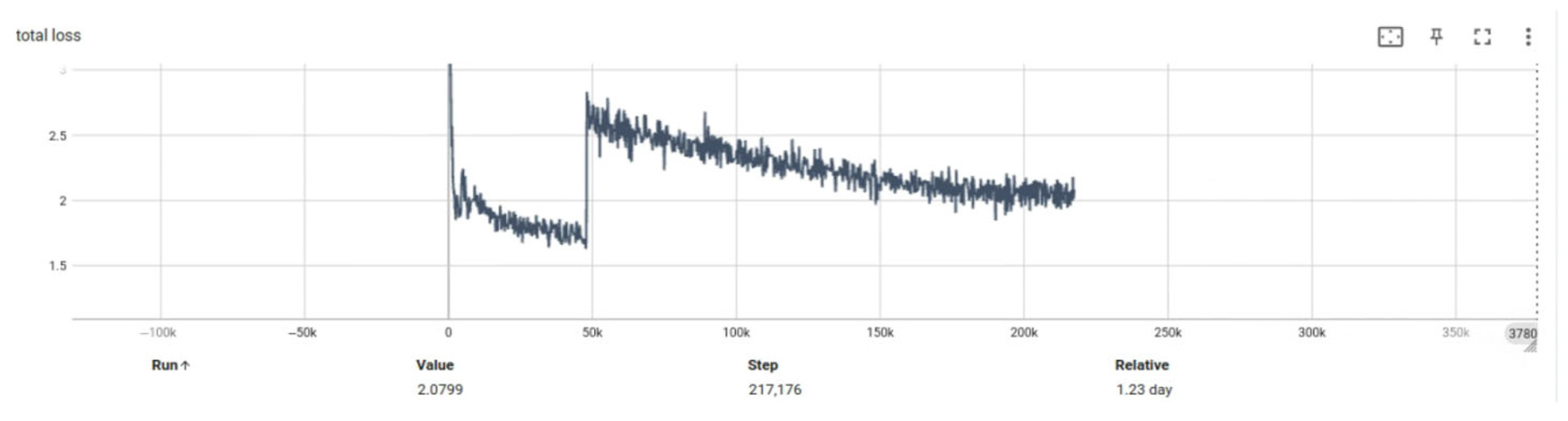
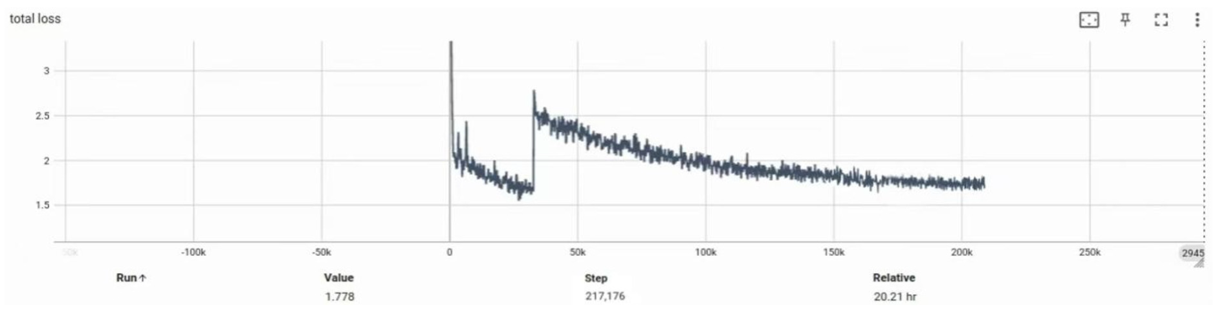
Experiment 2 aims to compare the network’s performance before and after introducing key modules, with a particular focus on the trend of total loss during training.
Figure 15 and
Figure 16 present the loss curve comparisons between the two configurations. It is evident that the incorporation of the multi-scale feature extraction module and the optical flow field module leads to a significant reduction in total loss. At epoch 50, the optimized model achieved a reduction of 0.3019 in total loss compared to the baseline model (denoted as BASE), indicating improved convergence efficiency and enhanced generalization capability.
This section further verifies the effectiveness of integrating the multi-scale feature extraction module and the optical flow field module into the base Transformer architecture. Using the original Transformer structure as the baseline (denoted as BASE), four comparative configurations were designed:
The performance differences of these models in correcting distorted wide-angle images are summarized in
Table 1.
This section further evaluates the effectiveness of integrating multi-scale feature extraction and optical flow modules into the baseline Transformer architecture (denoted as BASE). Four model variants were constructed based on this baseline, and their performance differences are summarized in
Table 2. Comparative experiments were conducted on the Places2 dataset, MS-COCO, and real-world wide-angle surveillance images.
Introducing the multi-scale feature extraction module alone resulted in a PSNR improvement from 22.21 dB to 25.36 dB (+3.15 dB), indicating that enhancing channel dimensionality and hierarchical depth significantly improves the model’s ability to represent fine image details. The inclusion of the optical flow module further increased the PSNR to 26.97 dB, demonstrating its strong guidance effect in modeling the directional structure of image distortions. When both modules were jointly incorporated, the model achieved the best performance, with a PSNR of 27.43 dB and SSIM of 0.8190, representing improvements of +5.22 dB and +0.0808 over the BASE model, respectively.
In addition, we evaluated the computational cost and inference efficiency of each model variant. As shown in the table, integrating both modules increased the parameter count from 26.85 M to 35.93 M and the FLOPs from 2.15T to 2.45T. Nonetheless, the average inference time was maintained at 9.5 ms, which satisfies real-time processing requirements (>10 FPS) on the Jetson TX2 NX platform. These results demonstrate that the proposed model achieves a favorable balance between performance gains and lightweight deployment suitability.
4.4.2. Ablation Study on Network Pruning for Wide-Angle Image Correction Deployment
This experiment compares the differences in model size, image correction quality, and inference speed before and after applying pruning-based optimization strategies to the wide-angle image correction network when deployed on an edge computing platform. The test results are shown in
Table 2. The baseline model (denoted as BASE) refers to the original network trained on the server. The parameter
represents the channel retention ratio during pruning; a higher
indicates that more channels are preserved. All experiments are conducted on the Jetson TX2 NX platform with an input image resolution of 1024 × 768.
The experimental results in
Table 2 indicate that although the correction network operates in real time on a server, its deployment on an edge computing platform results in an inference time of 104 ms per image frame. When integrated with the image stitching system, this latency fails to meet the real-time requirement of 15 FPS, necessitating pruning optimization of the original BASE network.
At a pruning rate of = 55%, the inference time is reduced to 31 ms; however, the correction quality deteriorates significantly, leading to poor visual outcomes and limiting its applicability in downstream registration tasks. In contrast, the configuration with = 75% offers a better balance between accuracy and efficiency. While the PSNR drops by only 4.01 dB compared to the BASE model, the inference time is reduced by 68 ms, and it is also 23 ms faster than the = 85% configuration. Based on this trade-off, we adopt = 75% as the final pruning ratio, achieving an optimal balance between performance and runtime efficiency for deployment on the embedded platform.
4.5. Comparative Analysis
- (1)
Evaluation of Convolution Kernel Configurations in the TPS Prediction Module
This experiment analyzes the impact of different convolutional kernel configurations, corresponding to varying numbers of TPS control points, on the rectification performance of the network. Specifically, we examine how the number of control points predicted at each layer of the TPS prediction module affects the output quality. Quantitative metrics, including PSNR and SSIM, are used for evaluation. The experimental results are summarized in
Table 3.
To investigate the impact of TPS control point density on correction performance, this study adjusts the output dimensions of convolutional layers in the TPS module to generate different numbers of control points (e.g., 10 × 10, 12 × 12, 16 × 16) and conducts systematic evaluations on a standard distortion dataset. The results are summarized in
Table 4. The experiments reveal that the relationship between the number of control points and correction accuracy is not linearly positive. Specifically, when all four TPS modules output 16 × 16 control points, the model—despite its theoretically stronger spatial fitting capacity—shows a notable performance drop in both PSNR and SSIM (16.34 dB, 0.5234), falling behind the medium-scale 12 × 12 configuration and even underperforming the initial 10 × 10 setting.
This phenomenon can be attributed to the following factors:
- (1)
Overfitting to local distortions: Excessive control points tend to overfit localized deformation regions, which reduces global correction smoothness and causes geometric inconsistencies across the image.
- (2)
Increased model complexity: A higher number of control points significantly increases the output dimensionality of the network, leading to greater computational overhead and potential training instability or gradient degradation—especially detrimental for embedded deployment.
- (3)
Enhanced noise sensitivity: In regions with blurred edges or weak textures, dense control points often lack sufficient semantic support, resulting in erroneous displacements and degraded correction accuracy.
In comparative experiments, certain existing methods (e.g., RecRecNet) exhibit significant performance degradation when applied to irregularly distorted images, with substantial drops in PSNR and SSIM. This is largely due to their limited geometric adaptability and lack of structural guidance. In contrast, the optical flow-guided vector constraint mechanism proposed in this study allows dynamic adjustment of TPS control point trajectories, introducing direction awareness into control point prediction. This enhances the model’s robustness and geometric stability in the presence of complex distortions.
Considering correction accuracy, model robustness, and computational efficiency, we adopt a hierarchical control point configuration (10 × 10, 10 × 10, 12 × 12, 14 × 14) as the final model setting. Under this configuration, the model achieves optimal performance, with the PSNR and SSIM reaching 19.97 dB and 0.6151, respectively. These findings highlight that properly regulating TPS control point density—along with direction-aware guidance—is a key strategy for improving wide-angle image correction quality and deployment efficiency.
- (2)
Comparison of Different Algorithms on Public Datasets
This experiment compares several mainstream algorithms for wide-angle image rectification and distortion correction. PSNR and SSIM are used as the primary evaluation metrics for quantitative analysis, and inference time is also measured for selected methods. The detailed results are presented in
Table 4.
The test dataset was synthesized using images from Places2 and MS-COCO, incorporating various types of distortions, including warping operations and radial distortion modeling approaches based on [
6,
45]. The final evaluation set covers irregular distortions, wide-angle distortions, and fisheye distortions, with all images resized to a resolution of 256 × 256.
Experimental results show that the proposed method outperforms several state-of-the-art baselines in both PSNR and SSIM, demonstrating superior distortion correction capability and image quality restoration across diverse distortion types. Additionally, it achieves faster inference speeds, ranking among the most efficient in the benchmark. In the wide-angle correction task, the proposed method improves the PSNR by 3.28 dB compared to MOWA. In the fisheye image correction task, it achieves a 2.18 dB gain in PSNR, while maintaining leading inference efficiency.
It is worth noting that methods such as Crop, ROP, and Padding rely on manual parameter adjustments and cannot be executed in an automated inference pipeline. Therefore, inference time is marked as “–” in the table to indicate exclusion from speed comparison.
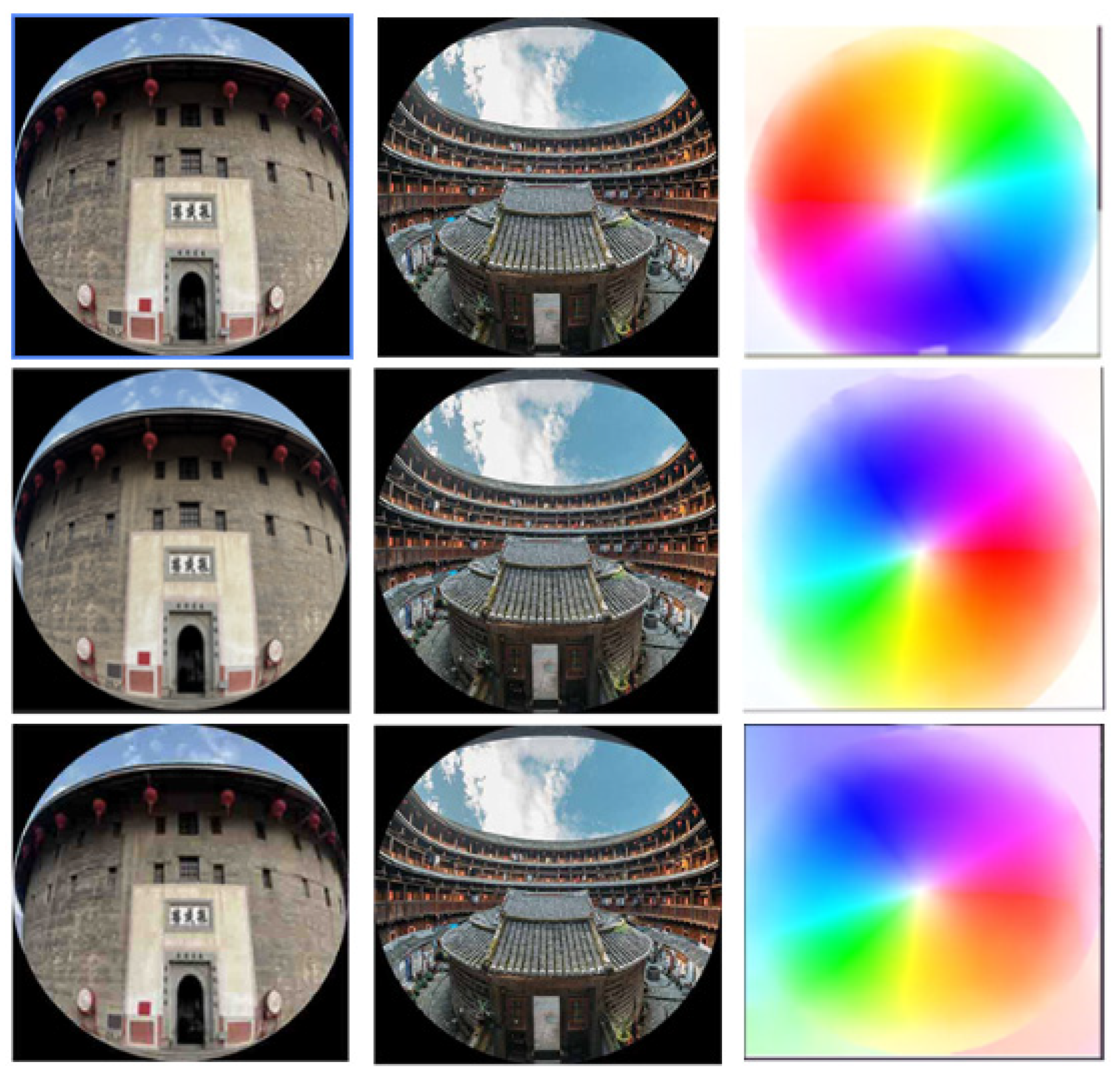
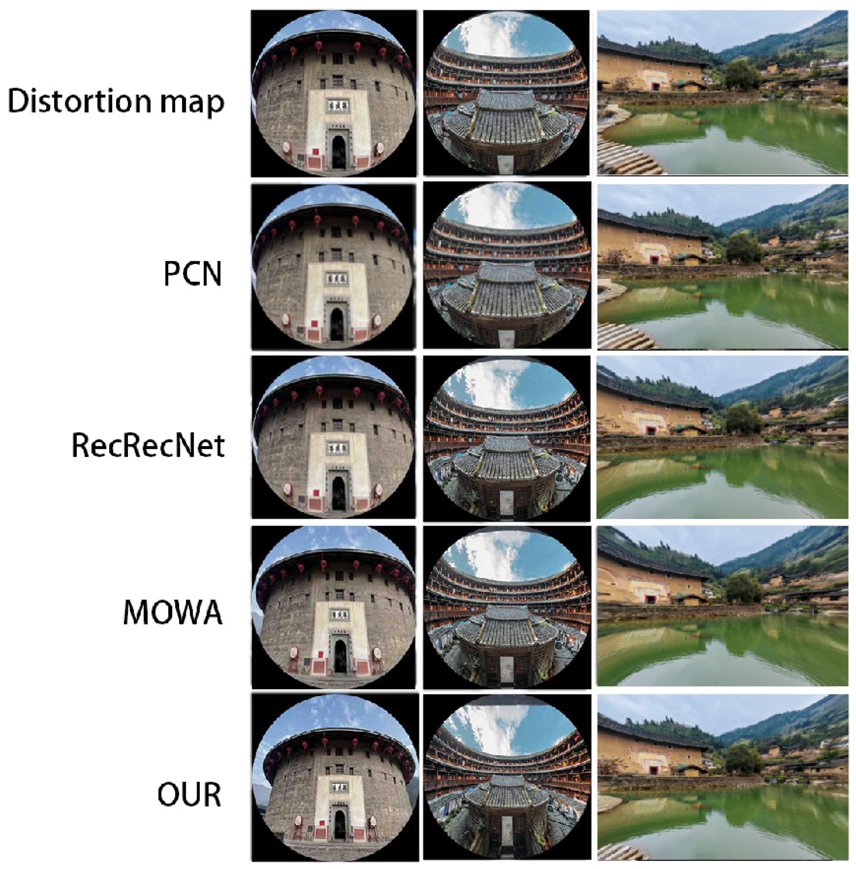
In the comparative experiments, the proposed method was evaluated using two widely adopted objective metrics—PSNR and SSIM—for quantitatively assessing the quality of rectified images. Additionally, a qualitative comparison based on subjective visual perception was conducted against existing state-of-the-art algorithms. As illustrated in
Figure 19, the proposed method exhibits superior overall performance in correcting wide-angle distortions, with particularly pronounced improvements in regions affected by severe deformation.
Moreover, test results on high-resolution and complex surveillance scenarios indicate that the proposed method exhibits stronger robustness and adaptability in restoring structural consistency and edge continuity compared to other baseline approaches. These advantages significantly enhance both the visual quality of the corrected images and their practical usability in real-world applications.
Experimental results demonstrate that the proposed multi-scale feature modeling mechanism, TPS control point prediction strategy, and optical flow-guided constraint collectively exhibit significant advantages in the geometric correction of high-resolution distorted images. Compared with existing methods, the proposed model achieves higher PSNR and SSIM scores on standard benchmark datasets, indicating superior image restoration quality.
In terms of processing efficiency, the proposed algorithm delivers faster inference speed while maintaining excellent correction performance. For instance, on distorted images with a resolution of 640 × 640 pixels, the model achieves a substantially lower average inference time compared to representative methods such as RecRecNet and MOWA, thereby fully meeting the real-time requirements of practical applications.
4.6. System Testing
4.6.1. Real-Time Dual-Camera Image Stitching Implementation
The real-time image stitching system was deployed on the Jetson TX2 NX edge computing platform, utilizing the DeepStream framework to capture dual-camera video streams. The system acquires the initial frame from each camera and performs pre-alignment, during which the computed homography matrices and optimal seam lines are stored in GPU memory. Upon completion of the initialization process, the real-time stitching module is activated, and the stitched output is streamed to a designated URL.
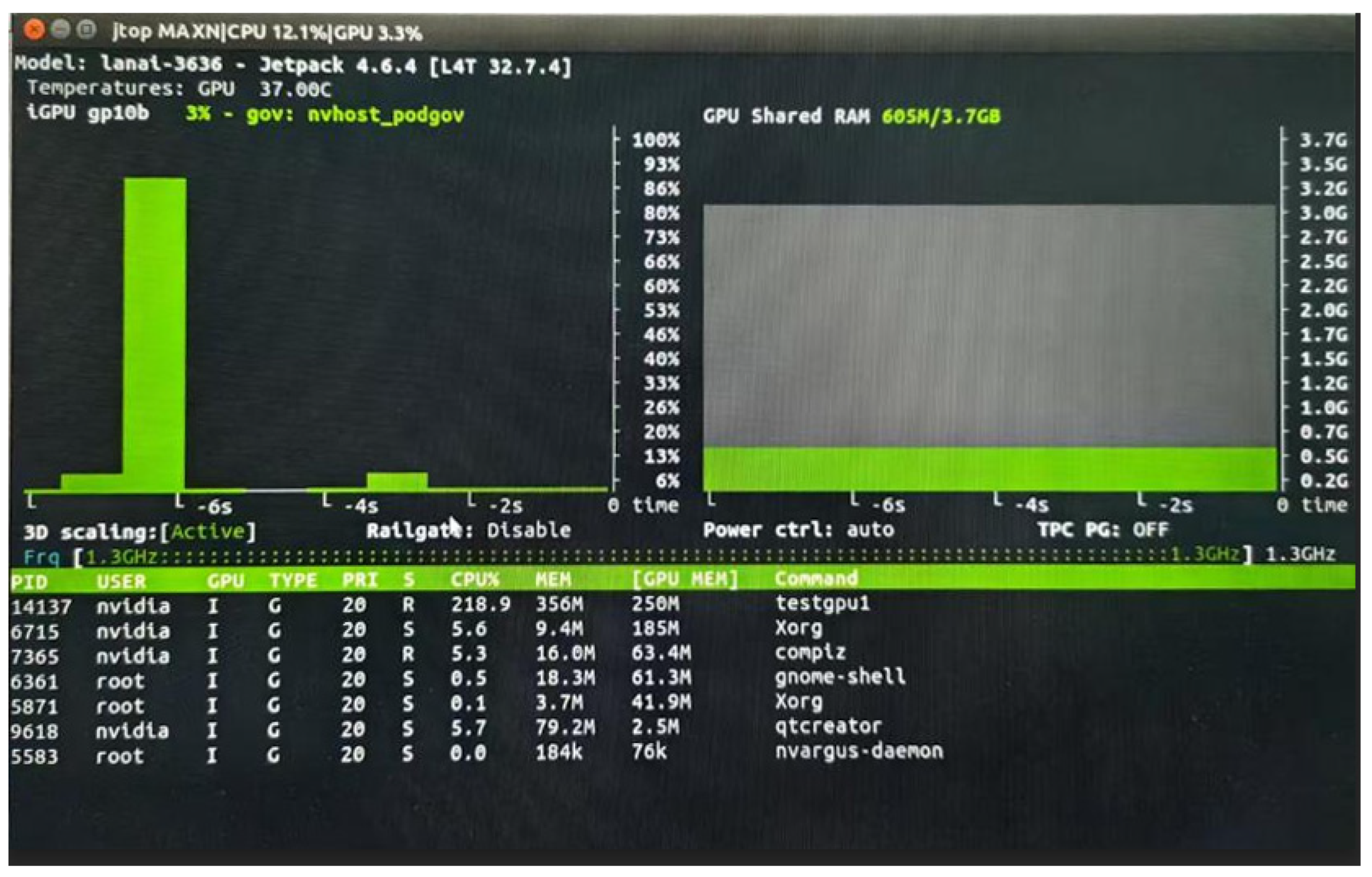
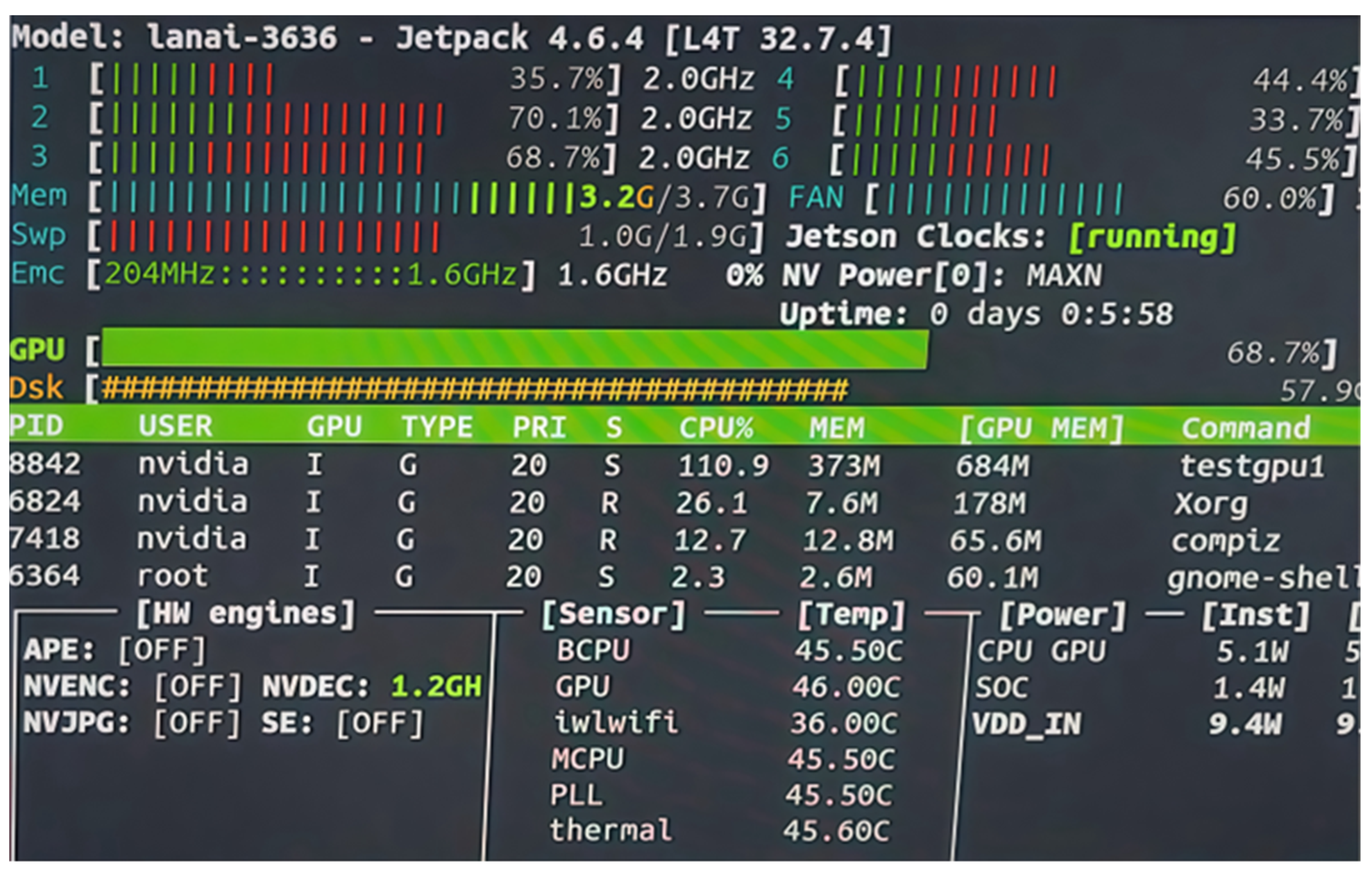
Without the integration of an object detection network, the system achieves a frame rate of 36 FPS, with six-core CPU utilization exceeding 50%, GPU usage at 19%, and memory consumption of approximately 250 MB. After incorporating the object detection network, the frame rate decreases to 27 FPS, CPU utilization increases to over 65%, GPU usage rises to an average of 68.7%, and memory usage reaches approximately 678 MB. Experimental results are illustrated in
Figure 20 and
Figure 21.
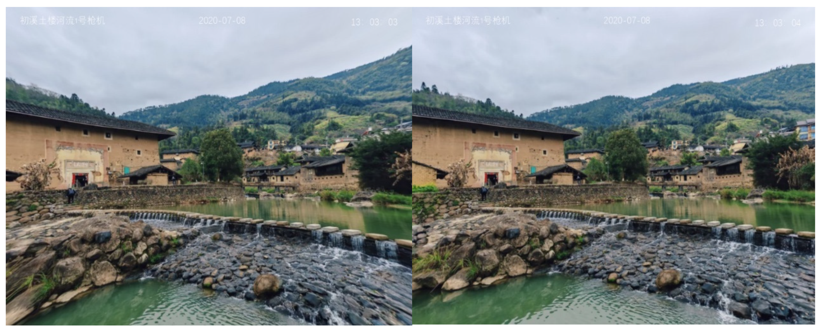
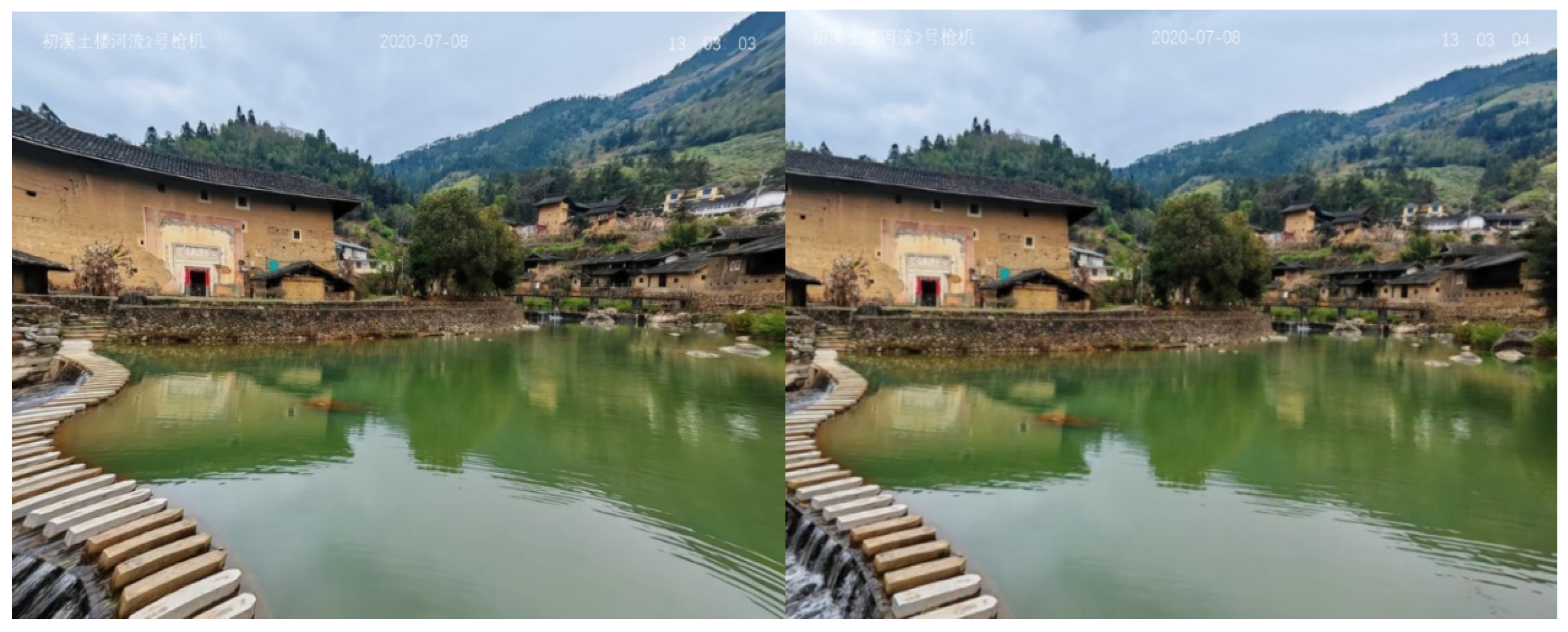
4.6.2. Wide-Angle Image Correction Implementation
In this study, the trained wide-angle image correction network was deployed on the Jetson TX2 NX edge computing platform to support model inference and perform distortion correction. During system execution, the input image to be corrected is fed into the deployed network, and the output is the corresponding geometrically corrected image. The correction results are illustrated in
Figure 22 and
Figure 23.
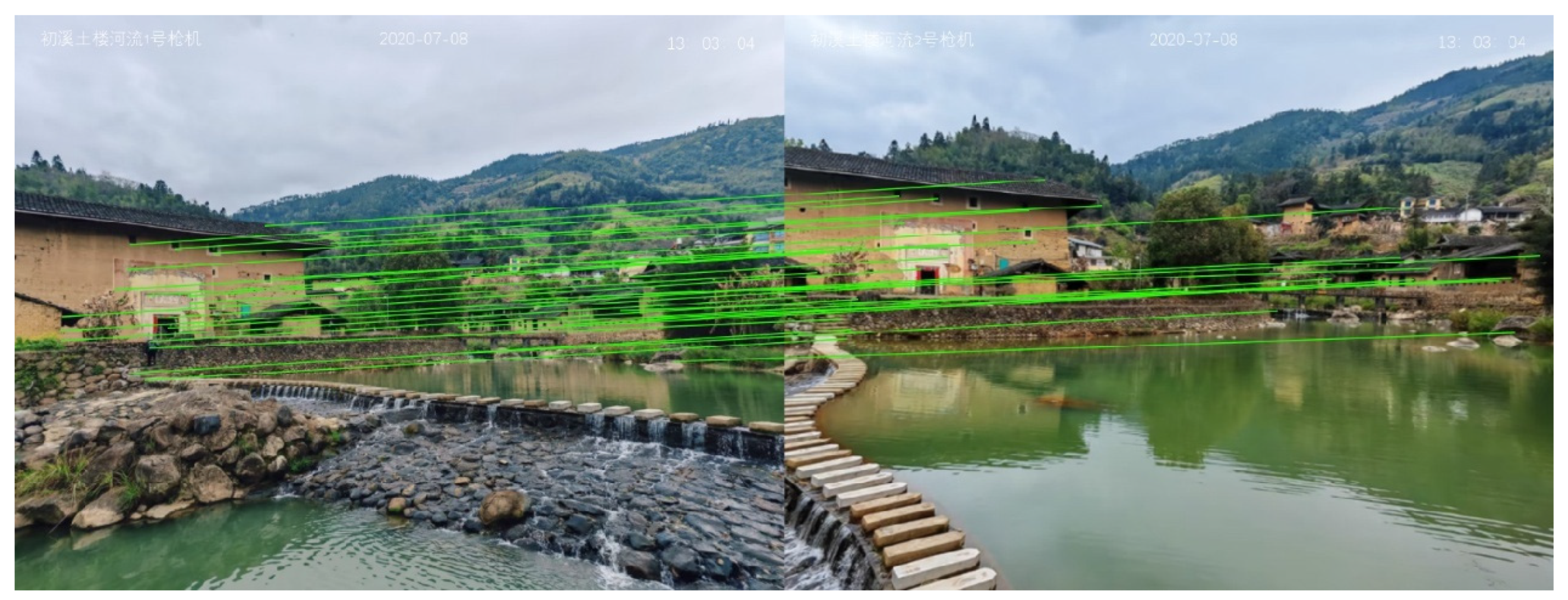
4.6.3. Wide-Angle Video Stitching Implementation
The real-time wide-angle image stitching system was deployed on the Jetson TX2 NX edge computing platform. Utilizing the DeepStream framework, dual wide-angle video streams were captured from two cameras. The first frame from each stream was first processed by the deployed correction network for distortion rectification. The precomputed homography matrices and optimal stitching seams (i.e., image registration and alignment parameters) were then stored in GPU memory to initiate the stitching process. The final stitched video output was streamed to a designated URL, as illustrated in
Figure 24 and
Figure 25.
In the tested configuration—featuring two wide-angle cameras each capturing images at a resolution of 1024 × 768 and producing a stitched output of 1400 × 1400 pixels—the system achieved a stable frame rate of 15 FPS on the Jetson TX2 NX platform. The correction network performed inference at 56 ms per frame, while the stitching operation required an additional 15 ms. The six-core CPU exhibited an average utilization exceeding 90%, and the GPU maintained an average utilization of 75%, with memory usage around 2031 MB.
Experimental results demonstrate that the proposed system is capable of delivering high-quality, low-latency wide-angle image stitching even under constrained embedded computing resources, effectively meeting real-time application requirements.
5. Conclusions
This study addresses the challenges of nonlinear distortion correction and real-time stitching in high-resolution wide-angle images for visual perception tasks. A lightweight image correction and system integration framework tailored for edge computing scenarios is proposed, introducing systematic innovations in both algorithmic design and engineering deployment efficiency.
At the algorithmic level, a direction-guided dynamic geometric constraint mechanism is introduced by incorporating optical flow vector directions into the TPS control point prediction path. Unlike conventional static or rule-based TPS configurations, the proposed method enables end-to-end dynamic adjustment of control points based on explicitly observed local deformation directions in the image, significantly improving the model’s adaptability and correction accuracy under complex nonlinear distortions.
Additionally, a multi-scale feature extraction module is designed by embedding sliding window attention mechanisms across different network levels, enabling joint modeling of multi-resolution image features. This not only enhances the network’s semantic perception and fine-grained structural representation capabilities but also reduces overall computational cost through feature map partitioning and channel compression strategies. The vector direction outputs from the optical flow estimation module are further integrated into the training process as structural guidance signals, directing parameter updates toward actual deformation directions. This improves convergence efficiency and generalization ability, thereby enhancing the model’s robustness to severe geometric distortions.
To address the high computational complexity of Transformer-based architectures in embedded deployments, this study adopts a lightweight Swin-Tiny encoder structure. Combined with L1 regularization and attention head/channel pruning strategies, the model is compressed along both the channel redundancy and attention redundancy dimensions. This results in approximately a 40% reduction in parameter count and a 40% increase in inference speed, effectively mitigating deployment bottlenecks under resource-constrained conditions.
On the deployment side, the proposed system is implemented on the Jetson TX2 NX platform using the DeepStream framework and a multithreaded optimization strategy. A dual-camera real-time stitching system is constructed, achieving a processing speed of 15 FPS at an image resolution of 1400 × 1400. The average correction latency is 56 ms, and the stitching delay is 15 ms. The system operates stably and responds efficiently, fully validating the proposed method’s feasibility and engineering applicability in embedded environments.
Although this study has made notable progress in algorithm design and system implementation, there remains considerable room for further improvement. Future research may proceed along the following directions:
Model lightweighting and cross-platform deployment: For lower-power edge devices (e.g., Jetson Nano or AI camera SoCs), advanced compression techniques such as model pruning, quantization, and knowledge distillation can be further explored to enhance deployment flexibility and adaptability across heterogeneous hardware platforms. Although the proposed model has been successfully deployed on the Jetson TX2 NX platform with favorable inference performance, most baseline algorithms are structurally complex or lack lightweight implementations, making it challenging to conduct unified benchmarking on embedded platforms. As such, this study primarily relies on inference time and model size measured in a server environment. Future work will focus on reconstructing and adapting representative baseline models for embedded deployment to establish a more comprehensive benchmarking framework.
Although the proposed model has achieved initial optimization in inference speed and structural compactness through the integration of the sliding window attention mechanism and multi-scale feature extraction strategy, it is primarily tailored for typical radial distortion scenarios. Its adaptability to more complex distortion patterns—such as extreme wide-angle or non-uniform distortions—remains limited. Future work may explore the incorporation of physics-based modeling constraints or multimodal information fusion strategies to enhance the model’s generalization ability and robustness across diverse nonlinear distortion conditions.
System-level integration and multi-task expansion: Building upon the current image correction framework, future developments may incorporate modules for object detection, behavior recognition, and other perception tasks. This will facilitate the creation of a more comprehensive edge-intelligent system tailored for practical applications in smart surveillance, industrial vision, and other real-world scenarios, thereby enhancing the system’s versatility and environmental adaptability.
In summary, this study presents a feasible technical pathway for wide-angle image correction modeling, system integration, and embedded deployment, providing both theoretical support and a practical foundation for the engineering application of visual perception technologies in resource-constrained environments.


