Article

Compound Instability Effect and Countermeasures of Pit-in-Pit in Collapsible Loess Strata

1
School of Highway, Chang’an University, Xi’an 710064, China
2
CCCC Second Highway Engineering Co., Ltd., Xi’an 710075, China
3
Changqing Engineering Design Ltd., Xi’an 710000, China
*
Author to whom correspondence should be addressed.
Appl. Sci. 2025, 15(14), 7710; https://doi.org/10.3390/app15147710 (registering DOI)
Submission received: 27 April 2025 / Revised: 25 June 2025 / Accepted: 4 July 2025 / Published: 9 July 2025

Abstract

The construction of pit-in-pit has become increasingly challenging due to the bad geological conditions, particularly in collapsible loess strata. To understand its supporting characteristics and failure mode, it is necessary to study the composite instability mechanism in the loess strata. This research systematically investigates the interacting instability modes of pit-in-pit under a collapsible loess stratum, studies the effects of different reinforcement parameters through physical model tests, analyzes the significance level of each reinforcement factor, and monitors the displacement of the foundation pit during construction in a pit project in Zhengzhou. The result shows that the soil pressure distribution law of the pit in a collapsible loess formation is a complex function of soil parameters, the relative positional relationship between the inner and outer foundation pits, and the time of immersion. The model test shows that the width and depth of reinforced soil have the most significant influence. The reinforcement measures proposed in this paper can effectively control the displacement of each measuring point during the foundation pit excavation, which can provide a reference for similar projects.

1. Introduction

China is the world’s most important loess distribution area. China’s loess distribution area is more than 640,000 square meters [1,2], accounting for about 6.3% of the total area of the country [3,4]. Loess has the characteristics of a porous granular structure [5,6,7], vertical joint development [8,9], and obvious difference between the dry and wet strength. Due to factors such as human causes and changes in the water environment, foundation pit engineering in loess areas often causes formation–deformation and structural instability [10], such as foundation pit soaking and slope collapse [11], as shown in Figure 1. Moreover, with the development of China’s urbanization process [12,13,14,15,16,17], the number of high-rise and deep underground construction projects is increasing, and foundation pit engineering is becoming more and more complex. The same foundation pit often needs to carry out multi-level excavation at the bottom of the pit, which is called the pit in pit engineering.
Due to the low strength of the loess strata, the water-rich environment, the complex soil pressure distribution, and the wide distribution of pressurized water, the construction of deep foundation pits faces problems such as soil slip, foundation pit instability, pile displacement, pit bottom uplift, the serious water leakage of the enclosure structure, and soil flow. On the other hand, due to the coupling influence of outer pit and inner pit excavation and unloading [18], compared with conventional pit excavation, the stress state of the soil associated with the stress path becomes more complicated [19]. In the analysis of the pile foundation performance, there are complex soil stress changes in the transition zone between the outer pit and the inner pit, which makes it more difficult to analyze the stress–strain state of the soil located in this area [20].
In the research of foundation pit engineering, scholars at home and abroad mainly adopt the Finite Element method (FEM), the Finite Difference method (FDM), and the Discrete Element method (DEM) to simulate the influence of excavation on the retaining structure and the surrounding soil. The FEM precisely calculates the structural response through unit discretization, the FDM discretely processes boundary problems through differential equations, and the DEM is good at simulating the mechanical behavior of granular materials such as soil and rock. Chen et al. [21] used the PLAXIS software to analyze the influence of the excavation depth of the inner pit and its relative position on the horizontal displacement of the retaining structure. It was concluded that the depth significantly impacted the displacement, and the horizontal displacement of the retaining structure decreased with the increase in the pit spacing. Xu Yizhi et al. [22] studied the influence of the area ratio and depth ratio on the equivalent depth coefficient of the outer pit wall through numerical model experiments. However, there are no calculation cases of collapsible loess areas at present. At present, the research on this type of foundation pit is mostly a simple description of the construction methods and support means, or a record of engineering cases. However, there are few in-depth theoretical studies. The common means of foundation pit reinforcement are also limited to enhancing the stiffness of the supporting structure.
Groundwater level variation directly affects soil’s effective stress and pore water pressure. Considering the influence of groundwater level variation in the numerical simulation process of foundation pit excavation is extremely important for analyzing the deformation of the retaining structure and soil and evaluating the stability of the foundation pit [23,24]. Meanwhile, in loess areas, due to the existence of collapsibility, the soil in the foundation pit is highly prone to local instability under the action of water, resulting in a local stress concentration and excessive displacement in the support [23,24,25].
General foundation pit engineering can refer to more design theories and engineering cases; the theory is more mature and the specification is more complete. For pits-in-pits, theoretical frameworks and design codes are lacking and there are few related cases, so it is difficult to conduct more scientific research and predictions on the overall deformation and damage of pits-in-pits after excavation, and it is also difficult to study control measures for different engineering cases [26]. It is urgent to expand and perfect the research of pit-in-pit and apply it to production practice.
Based on model tests and theoretical analysis, this paper establishes the composite instability mechanism of pit-in-pit in collapsible loess strata, studies the responses of pit-in-pit under different reinforcement parameters, and verifies it in a pit-in-pit project in Henan Province. This paper can provide a reference for similar projects in loess areas.
Figure 1. Foundation pit disaster in loess area [27].
Applsci 15 07710 g001

2. Instability Mechanism

Pit-in-pit refers to combined foundation pit engineering in which one or more foundation pits are continued to be excavated inside the foundation pit. As shown in Figure 2, shallower and deeper excavation areas are internal and external foundation pits.

2.1. Complex Stress System of Pit-in-Pit Structure

Foundation pit engineering has strong practicality and particularity in the construction process; it needs to constantly monitor and analyze and dynamically adjust the project [28]. In this section, the complex stress system of pit-in-pit is analyzed theoretically based on classical earth pressure theory [29]. 
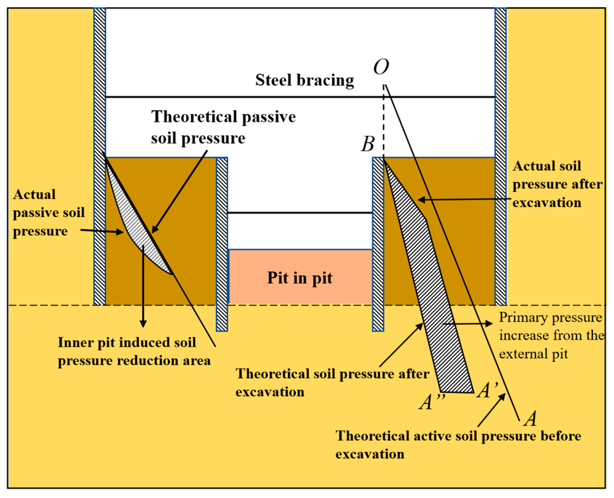
Figure 2 shows the complex stress system of the pit-in-pit structure, where the w is the distance between the inner pit and the outer pit, the h is the depth of the inner pit, and the b is the width of the inner pit. At this time, the overall stress state of the foundation pit becomes complicated and the soil pressure of the outer pit needs to be calculated by finite element software [30]. In the process of foundation pit excavation, as the soil is removed, the load on it is reduced, which will cause the soil at the bottom of the pit to produce an upward displacement tendency. If the excavation of the internal foundation pit continues, it will cause a change in the stress field and displacement field. Meanwhile, as the foundation pit system is in such a complex stress system, there is a great risk of settlement in the adjacent areas and on the surface caused by unloading.
Before the excavation of the foundation pit, the lateral earth pressure distribution curve of the soil was OA and the static lateral pressure coefficient was K0n. After the excavation of the foundation pit, the actual lateral earth pressure distribution curve became BA′. Due to the influence of unloading, the soil below the bottom of the pit is in a super-consolidated state. At this time, the static earth pressure coefficient increases to K0, where the K 0 = K 0 n OCR β . The excavation of a pit within a pit will cause the earth pressure acting on the pit within a pit retaining body to develop from the static lateral earth pressure distribution curve BA′ to the active earth pressure curve [31]. When designing the retaining structure of a pit within a pit, if the stress path change is not considered but it is believed that the earth pressure develops from the curve BA″ to the active earth pressure curve like in ordinary foundation pits, the magnitude of the earth pressure will be seriously underestimated. Thus, a complex stress system architecture involving the interaction of internal and external foundation pits is constructed, as shown in Figure 3.
At the same time, for the finite soil pressure in the pit, the angle between the failure plane and the horizontal plane is no longer the fixed value in the classical Rankine and Coulomb soil pressure theory 45 ° φ / 2 . It is a function of the soil mechanical properties, the distance between the inner pit and the outer pit envelope, and the width and depth of the pit in the calculated depth [32]. The above characteristics determine the complexity of the calculation of the force in the pit and the sensitivity of the parameters. When the pit in the pit is excavated in a special stratum, the complexity of the system will be further amplified [33], so the compound instability effect of the pit in the collapsibility loess stratum needs to be discussed separately [34].

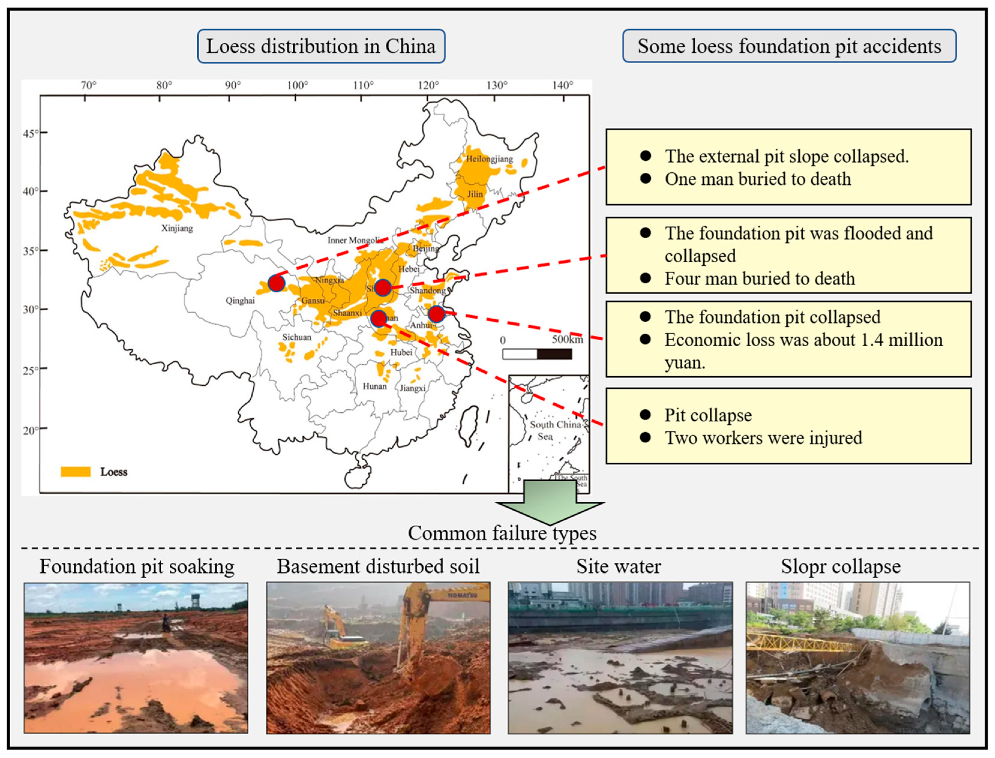
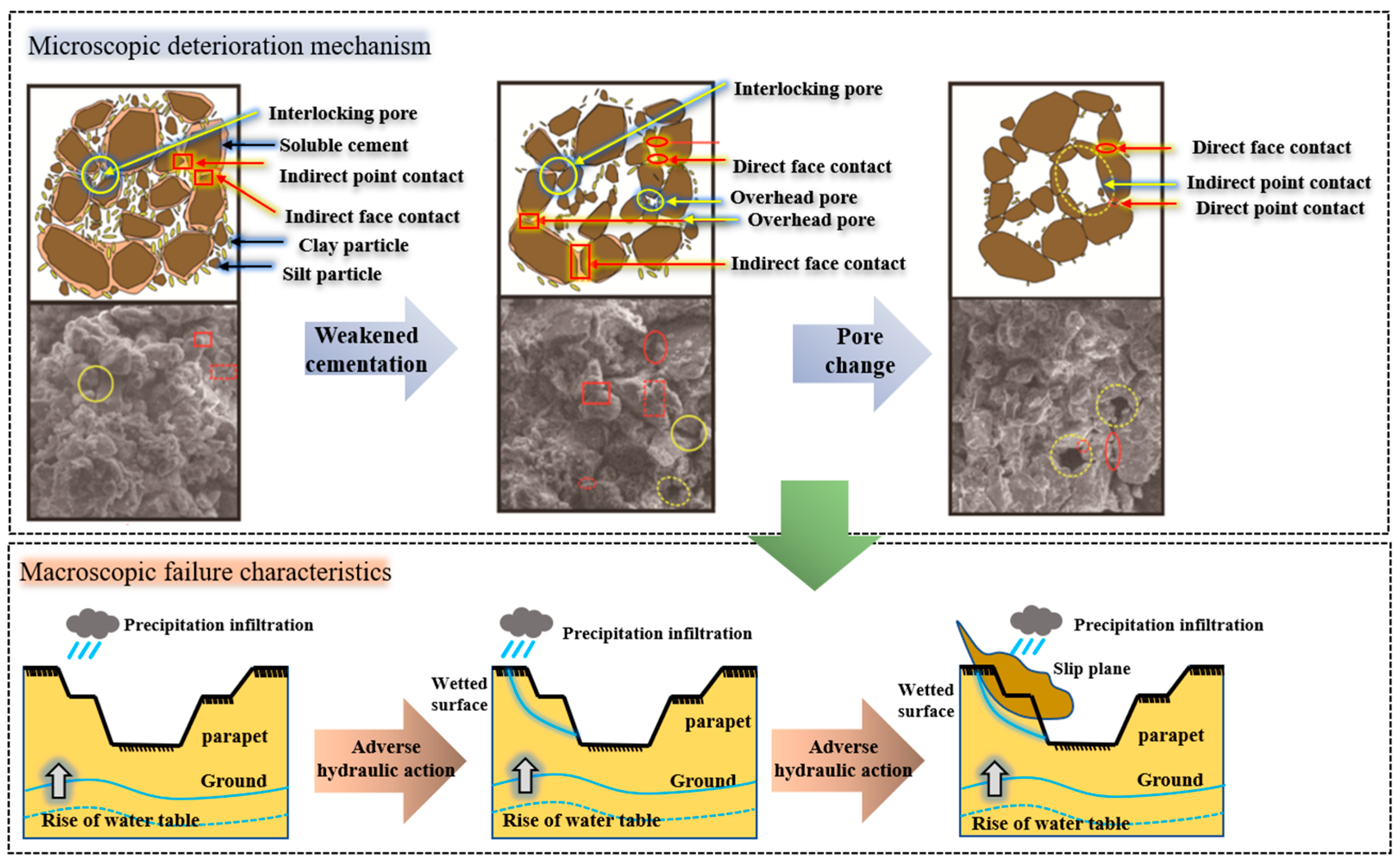
2.2. Characteristics of Collapsible Loess Degraded by Water

Loess exhibits relatively high shear strength in a dry environment. However, when exposed to water, its shear strength decreases. The most important factors affecting the change in the soil shear strength are the weakening of cementation and the change of pores [35], as shown in Figure 4. The undisturbed loess structure was transformed by leaching, which provided favorable conditions for disintegration caused by water infiltration. The presence of matric suction further accelerates this infiltration, causing the pore pressure inside the soil to rapidly increase until disintegration occurs [36].
For foundation pit engineering, when rainfall or groundwater begins to infiltrate the foundation pit soil, the soil strength is reduced to a critical value and instability failure will occur, as shown in Figure 4. At the same time, for unsaturated loess, due to the influence of its compaction and structural strength [37], the shear strength index of loess has its unique properties and the strength envelope also shows a special law, which does not fully conform to the Mohr–Coulomb criterion [38].
According to Zhang Maohua’s analysis of the undrained shear test data of collapsible loess, the envelope line of unsaturated loess is not straight, but a broken line composed of two straight lines and the turning point of the broken line is related to the structural strength [38]. The σ c is the normal stress at the critical point of structural strength and the two sections represent different structures and deformation forms of unsaturated loess. The front section maintains its original structure with small failure strain, while the latter section experiences significant structural changes and a loss of strength. The shear strength of collapsible undisturbed loess is expressed by a sectional line as follows:
τ = σ tg φ 1 + c σ < σ c σ c tg φ 1 + σ σ c tg φ 2 + c σ > σ c
The shear strength of soil is not only related to the properties of soil, but also to the drainage conditions, shear rate, stress state, stress history, and many other factors during the test, among which the most important are the drainage conditions during the test. According to the principle of effective stress, the effective stress strength parameter should be obtained from τ f = c + σ tan φ . 
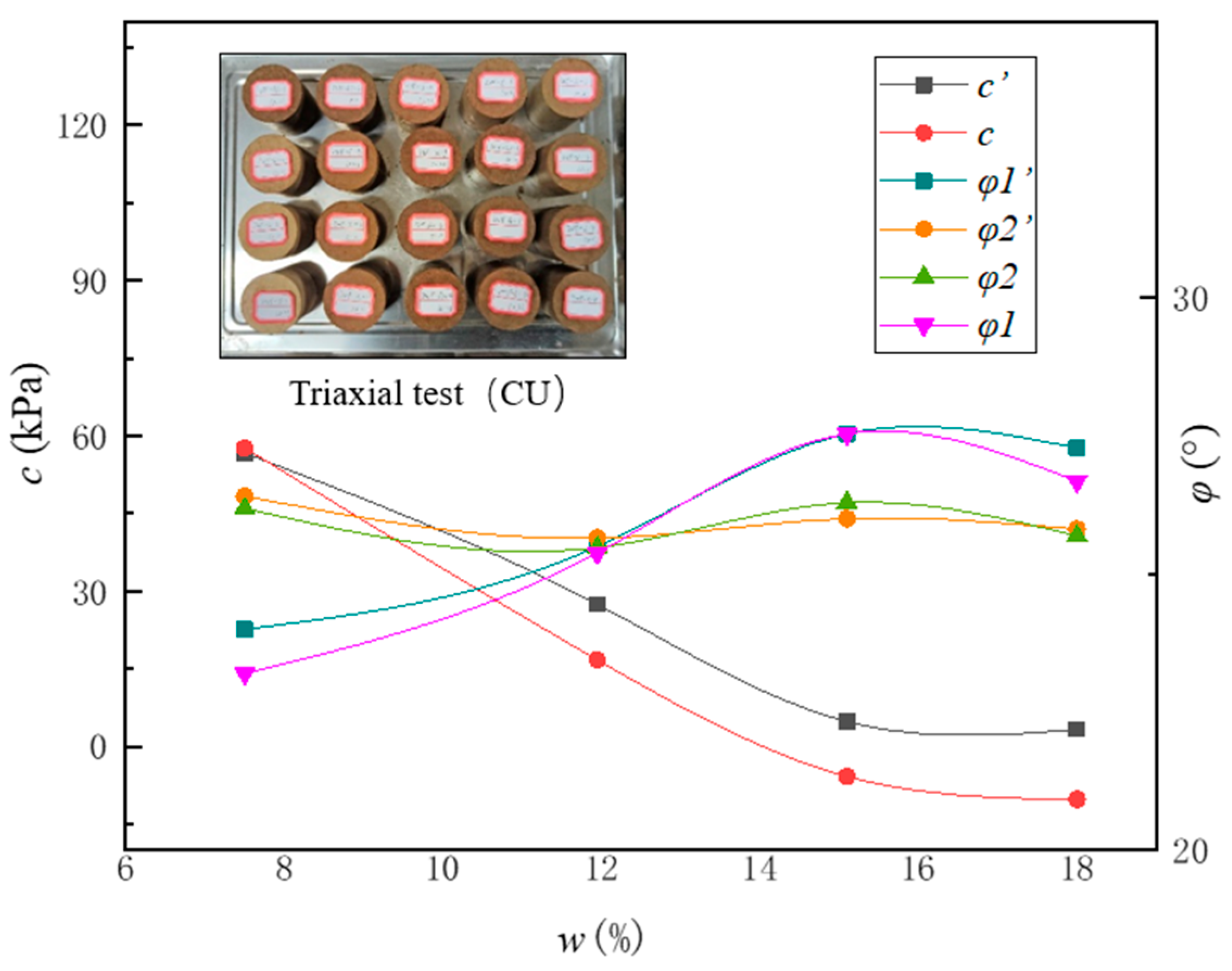
Figure 5 shows the soil shear strength index obtained by Zhang Maohua through the triaxial CU test. The data obtained from the test are fitted through spline functions, in which the soil shear strength index also changes with the change in the water content w, the cohesion index, and c decrease with the increase in the water content, but the friction angle and effective friction angle fluctuate with the change in the water content.
Numerous studies and reports on loess have confirmed that for loess in different regions, the change in the shear strength index is different [39,40], but all change with the water content, which is determined by the essential characteristics of loess. The general expression of the soil shear strength index is as follows:
( c , φ ) = f ( w )

2.3. Compound Instability Effect

Many scholars have studied the excavation mechanical response of pit-in-pit, and these studies point to the conclusion that the excavation of pit-in-pit will build a complex stress system structure involving the interaction of internal and external foundation pits. At the same time, for the above complex stress system, the traditional method of calculating the Rankine soil pressure formula will have a large numerical deviation from the actual situation [19].
Tan, Y et al. studied the mechanical response characteristics of pits within pits in special strata [19]. The research proves that for the complex stress system of pit-in-pit, the traditional engineering experience and calculation method are very likely to fail when excavation is carried out in the stratum with special mechanical properties. However, it is a pity that there is no research on the mechanical response characteristics of pits in collapsible loess areas. Pit excavation involves the secondary excavation unloading of the excavated soil in the foundation pit, which causes the redistribution of soil stress and horizontal displacement, and makes the mechanism and performance of the pile in the transition zone more complicated [41]. If precipitation or water table action occurs in the construction stage, the collapse action will make the stress state of the support structure in the transition zone more complicated and difficult to predict. Xie et al. [32] calculated the passive soil pressure of the foundation pit under the condition of pit-in-pit. According to the relative position relationship between the inner and outer pits, the sliding modes could be divided into four forms, as shown in Figure 6, and the passive soil pressure was derived accordingly.
It is assumed that: (1) the soil is rigidly shaped and the friction between the soil and the outer pit envelope is not considered; (2) the wall is vertical and the sliding surface is plane; (3) the soil is in a passive state, sliding upward, without considering the friction between the sliding soil and the pit support structure in the pit; and (4) the limited soil is c, φ homogeneous soil. When the slip surface does not pass through the inner pit (case ④), the slip soil is triangular and the shear failure angle is as shown in Equation (3) [32].
θ = π 4 φ 2
The sliding soil does not belong to the category of finite soil because the sliding surface does not pass through the inner pit. At this time, the shear failure angle is a fixed value, which is completely consistent with the results obtained from the classical soil pressure theory. When ω + b + h cot θ x , the entire inner pit is inside the sliding soil (case ①) and the shear failure angle is as shown in Equation (4) [32].
θ = arctan z ( 2 c + γ z tan φ ) tan 2 φ + 1 γ z 2 tan φ + 2 c z 2 γ b h 1 2 + 2 c z tan φ + γ z 2 tan 2 φ
When the shear failure angle θ is no longer a fixed value, but a function of the soil mechanical properties, calculated depth, pit width, and depth, its general expression is as shown in Equation (5).
θ = ( γ , φ , c , z , b , h )
When the positional relationship of the foundation pit is as in case ②, the shear failure angle is as shown in Equation (6).
θ = ( γ , φ , c , X , z , h )
Different from case ①, the distance between the inner pit and the outer pit envelope also becomes a factor affecting the shear failure angle of the slip surface.
When the positional relationship of the foundation pit is as in case ③, the shear failure angle is as shown in Equations (7) and (8).
When arctan z h X > φ ,
θ = arctan z h X
When arctan z h X φ ,
θ = φ
In case ③, the shear failure angle decreases with the increase in the distance between the inner pit and the outer pit envelope and the depth of the inner pit. The nonlinearity of the shear failure angle increases with the increase in the calculated depth. In Section 2.2, a general expression of the shear strength of loess under water immersion has been obtained ( c , φ ) = f ( w ) . When the water content changes, the change in the soil shear strength index will affect the soil pressure distribution in the pit, as shown in Equations (3)–(8). At the same time, when the friction angle ( φ ) changes, the relative position relationship between the internal foundation pit and the external foundation pit may change, for example, when the water content increases, θ will change and the relative relationship ③ of the internal and external foundation pit can be changed from the original mode to mode ②, as shown in Figure 6.
In the actual process of immersion, the moisture content in different regions of the soil is not the same, and the spatial distribution of the moisture content in the inner and outer pits will be a function of time. Therefore, the soil pressure distribution in the collapsible loess formation is a complex function of the soil parameters, the relationship between the internal and external pit positions, and the time of immersion.
To find the critical analytic solution of the failure mode, case ① is taken as an example. Assume that the expression of c(w) and ϕ(w) with the moisture content is shown in Equation (9) [25], where c0, ϕ0 are the initial moisture content state parameters and α, β are the deterioration coefficients. At this time, the driving displacement of the difference between the passive earth pressure Ep in the outer pit and the active earth pressure Ea in the inner pit is calculated, as shown in Equation (10), where K p = tan 2 45 ° + ϕ 2 , K a = tan 2 45 ° ϕ 2 .
c ( w ) = c 0 e α w , ϕ ( w ) = ϕ 0 β w
Δ E = E p E a = 1 2 γ D 2 K p 1 2 γ H 2 K a
When the shear force and shear strength of the slip surface are balanced, it can be derived that τ required   = γ h sin θ cos θ , also because τ = c ( w ) + γ h cos 2 θ tan ϕ ( w ) . The critical moisture content obtained by a simultaneous solution is shown in Equation (11).
w c = 1 α + β ln c 0 γ h sin θ cos θ γ h cos 2 θ tan ϕ 0

3. Influencing Factors of Instability Analysis

However, because the boundary effect is ignored and the Mohr–Coulomb criterion is used for the ultimate bearing capacity of soil, it cannot accurately reflect the actual failure behavior of soil under complex loads [42,43,44]. Therefore, it is necessary to conduct practical experiments to further study the complex instability effect of the pit in the collapsible loess stratum under the condition of flooding [45]. In this section, model tests are conducted to analyze the stress and deformation laws of the crater-in-pit structure under different size parameters, and to find the influence laws of the geometry and size parameters of the crater-in-pit structure on its mechanical response.

3.1. Similarity Theory

Model test dimensions are shown in Table 1. The value results of the similarity coefficient of this model test are shown in Table 2.

3.2. Test Preparation

The net dimensions of the test model box are 1.2 m long, 0.8 m wide, and 1.5 m high, as shown in Figure 7; the model box and the field layout are shown in Figure 7.
The loess samples used in the experiment were taken from a pit-in-pit project in Zhengzhou, Henan Province. We conducted an indoor geotechnical test to test the basic mechanical properties of the soil, and the test results are shown in Table 3. Surface rainfall infiltration is the main factor affecting the strata in which the pit is located. The method of uniform water sprinkling at the top is adopted to simulate the precipitation effect. The water inlet pipe is arranged at the top of the model box, and the drainage system is arranged at the bottom. Due to the complexity of the model test, geological structures existing in the loess strata, such as ground fissures and dominant infiltration channels, were not taken into consideration in the model test. Instead, this study only considered the influence of collapsible loess caused by precipitation on the structure of pits within pits under uniform loess strata.

3.3. Test Condition

The soil mass in the foundation pit shall be excavated in different layers. After the excavation reaches the corresponding elevation, it shall be left to stand for some time to ensure the stability of the data records at this stage, and then excavation downward will be continued, as shown in Figure 8. Two different factors are considered in this experiment, that is, the effect of different spacing and different height differences of internal and external foundation pits on soil settlement. Table 4 shows the distribution of horizontal factors of different vertical factors and related factors.
The dial meters are set up to measure the ground settlement at the location where the soil settlement needs to be measured. In the subsequent excavation process, stratified excavation is adopted, each excavation depth is 5 cm, and when the excavation reaches the predetermined depth, a little pause is made to ensure the accuracy of the current data. At the same time of excavation, the upper part of the water is sprayed to simulate the surface precipitation. For every 5 cm of excavation, a water spraying operation is carried out. The next excavation is carried out after the surface precipitation penetrates into the stratum [46,47].

3.4. Test Result

3.4.1. Force and Displacement of Outer Pit Envelope Structure

(1)
Different pit spacing
Figure 9 presents comparative analysis curves illustrating the influence of pit spacing on force and displacement distributions. Values on the right side of the supporting structure denote positive direction. The displacement trends of external piles exhibit similarity across varying distances between inner and outer foundation pits. Due to soil excavation and unloading effects, pile tops are displaced away from the excavation zone. Along the pile depth, maximum negative horizontal displacement occurs at the mid-height of external piles. This displacement gradually diminishes toward the pile tip. Notably, horizontal displacement at the lower pile segment becomes more pronounced as the pit spacing increases. Furthermore, bending moments in external piles show a moderate increase relative to initial conditions when the distance between inner and outer foundation pits expands.
(2)
Different pit height difference
The displacement curve of the external pile obtained under different elevation difference conditions of internal and external foundation pits is shown in Figure 10. The distribution of pile displacement is basically the same under the three working conditions, and it increases significantly from top to bottom, reaches a stable displacement change value in the middle of the pile, and maintains a stable horizontal displacement under the pile. With the increase in the height difference between the inside and outside foundation pit, the horizontal displacement of the pile body increases obviously, and the increasing trend is most obvious at the top of the pile, which will produce obvious bending deformation. Below the growth pole, the displacement of the pile has no obvious change.

3.4.2. Surface Displacement

(1)
Different pit spacing
Figure 11 presents time–history curves of vertical displacement at surface measurement points under varying pit spacings during foundation pit excavation. The test sequence comprised external pit excavation (0–180 s), followed by concurrent tunnel and internal pit excavation (60 s each), with a total duration of 300 s. Analysis reveals that reduced pit spacing significantly amplifies vertical displacement at comparable measurement points. These locations exhibit steady displacement growth during excavation, reaching peak values upon completion. Conversely, an increased distance between inner and outer foundation pits minimally affects vertical displacement in distant areas. Proximity to the external pit causes rapid initial displacement growth during its excavation phase. Subsequent construction activities exert a negligible influence on these distant measurement points due to their spatial separation from later excavation zones.
(2)
Different pit height difference
Figure 12 shows the time–history change curve of the vertical displacement of each measuring point on the surface of the foundation pit excavation under different height differences between the inner and outer pits. When the height difference between the inner and outer foundation pits is 10 cm, the test duration is the same as 300 s in the above section. When the height difference between the internal and external foundation pits is 30 cm and 50 cm, the duration increases by 360 s and 720 s, respectively, due to more excavation in the external foundation pit area.
The overall displacement development trend of the four measuring points is gradually increasing in the early stage. When the height difference between the inner and outer foundation pits is 50 cm, during the final tunnel excavation and the excavation of the inner foundation pit, since the depth of the inner foundation pit is already outside the range of affecting the external uplift, the later excavation of the inner foundation pit will cause the settlement of the measuring points to be excavated downward. The final vertical displacement value will be less than the value when the difference between the inner and outer pit height is 30 cm.
In this group of experiments, when the height difference between the inner and outer pits is 50 cm, the depth has exceeded the maximum depth to produce an uplift effect. In the process of continuous excavation, the vertical displacement of the outer surface will have a downward movement trend, and the final surface settlement will be smaller than the value when the height difference between the inner and outer pits is 30 cm.

4. Reinforcement Effect Analysis

In the previous section, we studied the influence of different pit geometry and size parameters on the stress and deformation of the envelope structure and the external surface displacement. This section analyzes the influence of different reinforcement parameters on the reinforcement effect.
In engineering practice, the parameters of foundation pit engineering are not completely refined and accurate, and the multiple superpositions of various internal and external influencing factors may produce other changing trends in the actual project. Given the above situation, this section will study the influence of various characteristic parameters of internal excavation on the properties of the pit from the perspective of the comprehensive influence of various factors. The maximum horizontal displacement of the external supporting pile structure, an important index of pit stability, will be used as the evaluation standard. Figure 13 summarizes the key information of this similar model test [48].
This time, the L25(56) orthogonal table was used, that is, the orthogonal table of 6 factors and 5 levels for 25 tests. To avoid the complexity of a large number of experimental operations, the orthogonal test method was used to arrange the test, and the minimum number of orthogonal tests was 25 times. Table 5 shows the combination of factors and levels. The 25 groups of orthogonal tests were calculated and the maximum calculated horizontal displacement of the pit in each group was obtained as the test result, as shown in Table 6. The mean value of one, two, three, four, and five in the orthogonal analysis table is the average value of the test results when the first, second, third, fourth, and fifth levels of a factor are taken.
Variance analysis was performed on the above test results, as shown in Table 7. The sum of the squares of deviation is S = m x i μ 2 , m is the number of orthogonal test levels, μ is the results of a single group, and is the mean of the results. After determining that the degree of freedom of the factor and the degree of freedom of the error are both five, the calculated F-value is compared with the critical F to determine whether each factor is significant. A larger F indicates a more significant factor, and an F value greater than F0.01(5.5) indicates that the factor has a 99% probability of being significant.
According to the F-value, the reinforcement width has the greatest effect on the displacement control of the external foundation pit maintenance unit, followed by the reinforcement depth. The F values of the other three parameters are all lower than F0.05(5,5), indicating that increasing the depth and thickness of the external enclosure has little influence on controlling the horizontal displacement of the soil envelope. When the reliability is 95%, the width and depth of the reinforced soil have the most significant effect on the horizontal displacement control of the external foundation pit enclosure and the internal foundation pit maintenance unit.

5. Engineering Application

5.1. Field Condition

The project is located in Zhengzhou City, Henan Province. According to the field survey data, the stratum of the project is a typical collapsible loess stratum. The project is located in a warm temperate continental monsoon climate; it is easy to cause the collapsible settlement of loess in the project area due to sudden rainfall during the construction of the foundation pit. At the same time, the groundwater resources near Changzhuang Reservoir are abundant. When the precipitation is abundant in summer, the groundwater level below the project area will rise under the influence of the reservoir water level. The location of the foundation pit project is shown in Figure 14.

5.2. Evaluation of Treatment

According to the analysis results of this paper, the recommended reinforcement measures are a 10 m depth, 6 m width, and 200 Mpa modulus [49]. According to the field monitoring results, the maximum surface settlement of the reinforced Section 2-2 converges to −25 mm, which meets the construction safety requirements.
The foundation pit project was monitored for 270 days and the displacement of each measuring point is shown in Figure 15. Vertical displacement and horizontal displacement show the same law and the displacement growth of each measuring point can be divided into three stages. In the second stage, the displacement of each measuring point increased rapidly, which was caused by the excavation of the outer pit. In the third stage, the construction of the inner foundation pit began. As shown in Figure 16, the displacement growth of the measuring points was relatively stable and the maximum vertical displacement of each measuring point was 97 mm, which was within the safe range. Due to the adoption of the reinforcement parameters obtained from the model test, the displacement of the inner foundation pit after excavation has been significantly controlled, which is consistent with the conclusion obtained from the model test. Meanwhile, since the water immersion condition set in the model test is the most unfavorable condition, the test results are significantly larger than those of the on-site test, which is acceptable.
At the same time, for the pit in the loess area, we should be successful in the construction process of each instance of index monitoring, especially for the rainy season construction. In addition, drainage systems should also be set up around the foundation pit, such as temporary drains, pumps, etc., to ensure that rainwater can be quickly removed to avoid pit water, avoid important construction processes in rainy days, such as excavation, concrete pouring, etc., avoid rain erosion or concrete condensation obstruction, and affect the quality of construction.
The construction of a foundation pit in the rainy season needs to strengthen waterproofing, drainage, and safety management, and be fully prepared to ensure that the construction process does not cause safety hazards or delays due to weather reasons.

6. Discussion

However, as predicted by the compound instability theory in Section 2.3 of this paper, the pit failure in the collapsibility loess area is a complex function of soil parameters, the relationship between internal and external pit positions, and the time of immersion. Due to the limitation of the research level, this paper considers the immersion project as the common change in the overall moisture content of the soil, which is an approximation of the actual situation. The seepage of loess is an extremely complex issue. There often exists a situation of local dominant infiltration. When the infiltration surface is no longer uniformly infiltrated as a whole [23], the reduction in the local strength of loess needs to be considered. The solutions to practical problems may deviate from the approximate assumptions proposed in this paper. To further accurately study the above problems, CFD (computational fluid dynamics) and fluid-structure coupling tools are needed, which can simulate the seepage path of soil more accurately and reduce the strength of the flooded area, which will be closer to the actual engineering. The possible future research direction is to use the fluid-structure coupling method to calculate the loess foundation pit projects with different permeability characteristics, and verify the influence of differences such as seepage paths and seepage flow rates on the structural stability.

7. Conclusions

Pit-in-pit engineering is a complicated engineering problem, especially in collapsible loess areas. In this paper, the combined instability effect of pit-in-pit in the collapse loess stratum is proposed, the influence of different geometric conditions and reinforcement factors on the safety of the foundation pit is studied, the numerical simulation calculation and analysis are carried out for a pit-in-pit project in Zhengzhou, Henan Province, and the corresponding reinforcement works and measures are proposed. The key findings are as follows:
(1) The soil pressure distribution law of the pit in a collapsible loess formation is a complex function of soil parameters, the relationship between the position of the pit and that of the pit, and the time of immersion. Under the condition of water immersion, the complex stress system of the pit-in-pit in the loess stratum will be disturbed, and the relative position relationship between the critical shear failure angle and the inner foundation pit will change. We have calculated the critical moisture content of the foundation pit instability under each parameter.
(2) The variation rules of the force and displacement of the inner and outer pits under different factors are obtained through a similar model. During the excavation process, the vertical displacement of adjacent measurement points increases significantly. However, the farther the distance between the inner and outer foundation pits, the smaller the influence of this factor on the vertical displacement in the far area. The height difference of the foundation pit has a relatively small influence on the displacement of the inner pit. Through the orthogonal test, it is found that the width and depth of the reinforced soil have the most significant effect on the horizontal displacement control of the external foundation pit enclosure unit and the internal foundation pit maintenance unit.
(3) Taking a pit-in-pit project in Zhengzhou, Henan Province, as an example, the pit displacement monitoring during the construction period is carried out. The results show that the reinforcement measures proposed in this paper can effectively control the displacement of each measuring point of the pit during the excavation process and can provide reference for similar projects.

Author Contributions

J.X.: Writing original draft, Investigation, Data curation, Conceptualization, Writing—review and editing. P.Y.: Investigation, Methodology. J.L.: Investigation, Data curation, Supervision. P.C.: Conceptualization, Supervision. X.S. (Xiangcheng Su): Writing—review and editing, Methodology. X.S. (Xulin Su): Investigation, Data curation. All authors have read and agreed to the published version of the manuscript.

Funding

The National Natural Science Foundation of China (52278393, 52078421), the Key R&D Program of Shaanxi Province (2023-YBSF-511, 2024SF-YBXM-635, 2023KXJ-159), and the Innovation Capability Support Program of Shaanxi (2023-CX-TD- 35).

Data Availability Statement

The raw data supporting the conclusions of this article will be made available by the authors on request.

Conflicts of Interest

Author Peilong Yuan was employed by the company CCCC Second Highway Engineering Co., Ltd. Peiyao Che was employed by the company of Changqing Engineering Design Ltd. The remaining authors declare that the research was conducted in the absence of any commercial or financial relationships that could be construed as a potential conflict of interest.

References

  1. Zhu, Y.J.; Jia, X.X.; Qiao, J.B.; Shao, M.A. What is the mass of loess in the Loess Plateau of China. Sci. Bull. 2019, 64, 534–539. [Google Scholar] [CrossRef] [PubMed]
  2. Liu, X.; Tan, W.; Xu, S.; Lv, Y.; Niu, D.; Mahmoud, H.N. Experimental and numerical investigation of freeze-thaw damaged RC beams subject to impact loading. Eng. Struct. 2025, 338, 120545. [Google Scholar] [CrossRef]
  3. Tang, K.; Liu, D.; Xie, S.; Qiu, J.; Lai, J.; Liu, T.; Fang, Y. Analysis of loess water migration regularity and failure response of tunnel structure under rainfall environment. Bull. Eng. Geol. Environ. 2024, 83, 1–22. [Google Scholar] [CrossRef]
  4. Zhao, Z.-H.; Sun, H.; Zhang, N.-X.; Xing, T.-H.; Cui, G.-H.; Lai, J.-X.; Liu, T.; Bai, Y.-B.; He, H.-J. Application of unmanned aerial vehicle tilt photography technology in geological hazard investigation in China. Nat. Hazards 2024, 120, 11547–11578. [Google Scholar] [CrossRef]
  5. Guo, E.; Zhang, W.; Lai, J.; Hu, H.; Xue, F.; Su, X. Enhancement of Cement-Based Materials: Mechanisms, Impacts, and Applications of Carbon Nanotubes in Microstructural Modification. Buildings 2025, 15, 1234. [Google Scholar] [CrossRef]
  6. Guo, E.; Hu, H.; Lai, J.; Zhang, W.; He, S.; Cui, G.; Wang, K.; Wang, L. Deformation analysis of high-speed railway CFG pile composite subgrade during shield tunnel underpassing. Structures 2025, 78, 109193. [Google Scholar] [CrossRef]
  7. Qian, X.; Qiu, J.; Lai, J.; Liu, Y. Guarantee Rate Statistics and Product-Moment Correlation Analysis of the Optimal Deformation Allowance for Loess Tunnel in China. Appl. Sci. 2025, 15, 2451. [Google Scholar] [CrossRef]
  8. Smalley, I.; Marković, S.B. Controls on the nature of loess particles and the formation of loess deposits. Quat. Int. 2019, 502, 160–164. [Google Scholar] [CrossRef]
  9. Fan, H.; Liu, T.; Zhang, S.; He, H.; Zhu, Z.; Zhu, Y.; Gao, X. Effects of Jet-Grouting Piles on Loess Tunnel Foundation with Centrifugal Model Tests. Int. J. Géméch. 2023, 23, 04022298. [Google Scholar] [CrossRef]
  10. Mei, Y.; Li, Y.-L.; Wang, X.-Y.; Wang, J.; Hu, C.-M. Statistical Analysis of Deformation Laws of Deep Foundation Pits in Collapsible Loess. Arab. J. Sci. Eng. 2019, 44, 8347–8360. [Google Scholar] [CrossRef]
  11. Li, H.; Du, L.L.; Yang, Z.H.; Zhang, X.H. Study on Safety Performance-Based Model for Deep Foundation Pit of Loess Area in Shaanxi. In Proceedings of the 5th International Symposium on Safety Science and Technology, Changsha, China, 24–27 October 2006; pp. 2081–2085. [Google Scholar]
  12. Xie, J.; Li, P.; Zhang, M.; Cao, L.; Jia, F.; Li, S. Analytical investigation of the shield-soil rotary friction on tunnelling-induced ground mechanical reactions. Comput. Geotech. 2023, 165, 105922. [Google Scholar] [CrossRef]
  13. Wei, Y.; Kong, W.; Wang, Y.; Sha, A. Multifunctional application of nanoscratch technique to characterize cementitious materials. Cem. Concr. Res. 2021, 140, 106318. [Google Scholar] [CrossRef]
  14. Zhang, Z.-K.; Lai, J.-X.; Song, Z.-P.; Xie, Y.-L.; Qiu, J.-L.; Cheng, Y.; Zhang, L. Investigating fracture response characteristics and fractal evolution laws of pre-holed hard rock using infrared radiation: Implications for construction of underground works. Tunn. Undergr. Space Technol. 2025, 161, 106594. [Google Scholar] [CrossRef]
  15. Wang, Z.; Wang, J.; Wu, H.-N.; Zhang, R.; Zhang, G.-Y.; Zhang, F.; Mariani, S. Investigation of the microstructure, mechanical properties and thermal degradation kinetics of EPDM under thermo-stress conditions used for joint sealing of floating prefabricated concrete platform of offshore wind power. Constr. Build. Mater. 2025, 485, 141897. [Google Scholar] [CrossRef]
  16. Xu, J.B.; Wu, X.; Qiao, W.; Wang, S.W.; Shu, S.; Zhao, D.N.; Chen, X.Y. Life cycle carbon emission assessment for ecological protection slopes: Focus on construction and maintenance phases. J. Clean. Prod. 2025, 497, 145174. [Google Scholar]
  17. Wang, J.; Fang, Q.; Zheng, G.L.; Wang, G.; Chen, J.Y.; Zhang, J.L.; Zhao, P. Influences of bit button wear on performance of rotary-percussive drilling: MBD-DEM coupling simulation and verification. J. Rock Mech. Geotech. Eng. 2025, 17, 1585–1598. [Google Scholar] [CrossRef]
  18. Sun, Y.; Xiao, H. Wall Displacement and Ground-Surface Settlement Caused by Pit-in-Pit Foundation Pit in Soft Clays. KSCE J. Civ. Eng. 2021, 25, 1262–1275. [Google Scholar] [CrossRef]
  19. Tan, Y.; Lu, Y.; Xu, C.; Wang, D. Investigation on performance of a large circular pit-in-pit excavation in clay-gravel-cobble mixed strata. Tunn. Undergr. Space Technol. 2018, 79, 356–374. [Google Scholar] [CrossRef]
  20. Hu, H.; Yang, M.; Lin, P.; Lin, X. Passive Earth Pressures on Retaining Walls for Pit-in-Pit Excavations. IEEE Access 2018, 7, 5918–5931. [Google Scholar] [CrossRef]
  21. Chen, L.Y.; Li, J.P.; Liang, F.Y.; Liao, Z.J. Numerical analysis for effect of pit in foundation pit on lateral displacement ofsupporting structure. Chin. J. Geotech. Eng. 2008, 30, 56–91. [Google Scholar]
  22. Xu, Y.Z.; Liao, S.M.; Zhou, S.H.; Shen, M.L. A computation method of equivalent depth for pit-in-pit excavation structural design in soft ground of Shanghai. Rock Soil Mech. 2012, 33, 2313–2318. [Google Scholar]
  23. Qiu, J.; Cui, G.; Lai, J.; Zhao, K.; Tang, K.; Qiang, L.; Jia, D. Influence of fissure-induced linear infiltration on the evolution characteristics of the loess tunnel seepage field. Tunn. Undergr. Space Technol. 2025, 162, 106640. [Google Scholar] [CrossRef]
  24. Su, X.; Zhang, C.; Zou, Z.; Wang, Y.; Lai, J.; Liu, T. Influence of Water Rock Interaction on Stability of Tunnel Engineering. Pol. J. Environ. Stud. 2024, 34, 535–548. [Google Scholar] [CrossRef] [PubMed]
  25. Qiu, J.; Liu, D.; Zhao, K.; Lai, J.; Wang, X.; Wang, Z.; Liu, T. Influence spatial behavior of surface cracks and prospects for prevention methods in shallow loess tunnels in China. Tunn. Undergr. Space Technol. 2023, 143, 105453. [Google Scholar] [CrossRef]
  26. Wu, M.B.L.; Dai, Y.M.; Yu, Q. Design and monitoring of retaining of pits in foudation-pit. Chin. J. Geotech. Eng. 2006, 28, 2081–2085. [Google Scholar]
  27. Xu, Z.; Cai, N.; Li, X.; Xian, M.; Dong, T. Risk assessment of loess tunnel collapse during construction based on an attribute recognition model. Bull. Eng. Geol. Environ. 2021, 80, 6205–6220. [Google Scholar] [CrossRef]
  28. Sun, Y.; Zhou, S.; Luo, Z. Basal-heave analysis of pit-in-pit braced excavations in soft clays. Comput. Geotech. 2017, 81, 294–306. [Google Scholar] [CrossRef]
  29. Wu, K.; Zheng, X.; Zhao, N.; Shao, Z. Effect of compressible layer on time-dependent behavior of soft-rock large deformation tunnels revealed by mathematical analytical method. Appl. Math. Model. 2023, 126, 457–481. [Google Scholar] [CrossRef]
  30. Korkmaz, M. A study over the general formula of regression sum of squares in multiple linear regression. Numer. Methods Partial. Differ. Equ. 2020, 37, 406–421. [Google Scholar] [CrossRef]
  31. Chen, C.; Di, G.E.; Wang, W.D. Design of Retaining System of Local Deep Excavations in Foundation Pits in Soft Ground. Chin. J. Geotech. Eng. 2008, 30, 1234–1239. [Google Scholar]
  32. Xie, L.X. Analysis of the Influence of Pit-in-Pit to Foundation Pit. Master’s Thesis, Zhejiang University, Hangzhou, China, 2016. [Google Scholar]
  33. Tao, H.; Ye, S.; Zhang, S. Monitoring and numerical simulation analysis of a pit-in-pit excavation of the first branch line of Lanzhou Metro. Appl. Rheol. 2023, 33, 20230111. [Google Scholar] [CrossRef]
  34. Pan, Y.; Zhou, X.; Han, S.; Zhang, L.; Cui, P. New Method for Calculating Soil Pressure on Shallow Underground Structures in Layered Soil. Geotech. Geol. Eng. 2024, 42, 5731–5752. [Google Scholar] [CrossRef]
  35. Huo, B.; Huang, Q.; Kang, X.; Liu, X.; Liu, M.; Peng, J. Experimental study on the disintegration characteristics of undisturbed loess under rainfall-induced leaching. CATENA 2023, 233, 107482. [Google Scholar] [CrossRef]
  36. Liu, Z.; Liu, F.Y.; Ma, F.L.; Wang, M.; Bai, X.H.; Zheng, Y.L.; Yin, H.; Zhang, G.P. Collapsibility, composition, and microstructure of loess in China. Can. Geotech. J. 2016, 53, 673–686. [Google Scholar] [CrossRef]
  37. Lou, Y.; Yoon, J.W.; Huh, H. Modeling of shear ductile fracture considering a changeable cut-off value for stress triaxiality. Int. J. Plast. 2014, 54, 56–80. [Google Scholar] [CrossRef]
  38. Zhang, M.H. Experimental Study on Deformation Behavior of Collapsible Loess. Master’s Thesis, Chang’an University, Xi’an, China, 2002. [Google Scholar]
  39. Wang, L.; Cheng, W.-C.; Xue, Z.-F. Investigating microscale structural characteristics and resultant macroscale mechanical properties of loess exposed to alkaline and saline environments. Bull. Eng. Geol. Environ. 2022, 81, 1–17. [Google Scholar] [CrossRef]
  40. Qin, Y.; Chen, Y.; Lai, J.; Qiu, J.; Wang, Z.; Liu, T.; Zan, W. Failures in loess slope-tunnel system: An overview of trigging sources, acting mechanism and mitigation strategies. Eng. Fail. Anal. 2024, 158, 107996. [Google Scholar] [CrossRef]
  41. Tong, L.; Li, H.; Ha, S.; Liu, S. Lateral bearing performance and mechanism of piles in the transition zone due to pit-in-pit excavation. Acta Geotech. 2021, 17, 1935–1948. [Google Scholar] [CrossRef]
  42. Talesnick, M. Measuring soil pressure within a soil mass. Can. Geotech. J. 2013, 50, 716–722. [Google Scholar] [CrossRef]
  43. Zhang, J.S. Analysis of the Calculation Method of Active Earth Pressure of Unsaturated Expansive Soil. In Proceedings of the Global Conference on Civil, Structural and Environmental Engineering/3rd International Symposium on Multi-Field Coupling Theory of Rock and Soil Media and Its Applications, China Three Gorges University, Yichang, China, 20–21 October 2012; pp. 180–185. [Google Scholar]
  44. Ostadan, F. Seismic soil pressure for building walls: An updated approach. Soil Dyn. Earthq. Eng. 2005, 25, 785–793. [Google Scholar] [CrossRef]
  45. Tang, G.C.; Shang, C.K.; Qin, Y.W.; Lai, J.X. Current Advances in Flame-Retardant Performance of Tunnel Intumescent Fireproof Coatings: A Review. Coatings 2025, 15, 99. [Google Scholar] [CrossRef]
  46. Tu, S.; Li, W.; Zhang, C.; Wang, L.; Jin, Z.; Wang, S. Seepage effect on progressive failure of shield tunnel face in granular soils by coupled continuum-discrete method. Comput. Geotech. 2023, 166, 106009. [Google Scholar] [CrossRef]
  47. Tu, S.; Li, W.; Zhang, C.; Chen, W. Effect of inclined layered soils on face stability in shield tunneling based on limit analysis. Tunn. Undergr. Space Technol. 2022, 131, 104773. [Google Scholar] [CrossRef]
  48. Fang, K.; Tang, H.; Li, C.; Su, X.; An, P.; Sun, S. Centrifuge modelling of landslides and landslide hazard mitigation: A review. Geosci. Front. 2023, 14, 101493. [Google Scholar] [CrossRef]
  49. Wei, F.; Lai, J.; Su, X. Investigation of Power-Law Fluid Infiltration Grout Characteristics on the Basis of Fractal Theory. Buildings 2025, 15, 987. [Google Scholar] [CrossRef]
Figure 2. Typical structure of pit-in-pit.
Applsci 15 07710 g002
Figure 3. Pit-in-pit complex stress system.
Applsci 15 07710 g003
Figure 4. Deterioration mechanism of loess immersed in water and instability engineering of foundation pit.
Applsci 15 07710 g004
Figure 5. Shear strength under different moisture contents.
Applsci 15 07710 g005
Figure 6. Pothole failure pattern before and after flooding.
Applsci 15 07710 g006
Figure 7. Schematic diagram of similar model test.
Applsci 15 07710 g007
Figure 8. Main flow of excavation experiment.
Applsci 15 07710 g008
Figure 9. Mechanical response of pit with different pit spacing.
Applsci 15 07710 g009
Figure 10. Mechanical response of pit with different pit height differences.
Applsci 15 07710 g010
Figure 11. Comparison of surface displacement at different internal and external intervals.
Applsci 15 07710 g011
Figure 12. Comparison of surface displacement with different pit height differences.
Applsci 15 07710 g012
Figure 13. Summarized for physical model test.
Applsci 15 07710 g013
Figure 14. Location of foundation pit engineering (the distribution map of loess shown in the figure is cited from reference [27]).
Applsci 15 07710 g014
Figure 15. Site plan and reinforcement profile.
Applsci 15 07710 g015
Figure 16. Displacement of each monitoring point.
Applsci 15 07710 g016
Table 1. Model test dimensions.
ModelPositionLife Size/cmAdjusted Size/cmFinally Size/cm
outer pitlong side28027090
short side17015050
pit depth28.9–31.83010
excavation depth28.9–31.83010
inner pitlong side68.96020
short side38.13010
pit depth283010
excavation depth59.86020
Table 2. Similarity coefficients of each parameter.
ArgumentSevere ( γ )Poisson Ratio ( μ )Angle of Internal Friction ( φ )Cohesive Force (c)
similarity criterion C γ = 1 C μ = 1 C φ = 1 C c = C σ
similarity coefficient1111
argumentstress ( σ )displacement ( δ )geometric dimension ( L )modulus of elasticity ( E )
similarity criterion C σ = C γ C L C δ = C ε C L C L = 300 C E = C σ
similarity coefficient300300300300
Table 3. Physical and mechanical properties of experimental loess.
Moisture ContentSevereDry WeightSaturationVoid RatioLiquid LimitPlastic LimitCohesionFriction Angle
units ω / % γ / kN / m 3 γ d / kN / m 3 S r / % e W L / % W P / % c / kPa °
value15.114.712.7361.1327.917.023.124.1
Table 4. Overview of model working conditions.
Simulated ConditionLongitudinal FactorIntervalDepth Difference
1distance between two pits010
220~
340~
4depth difference between the two pits~30
5~50
Table 5. Level table of orthogonal test factors.
VariateLevel
12345
reinforced soil width/cm79111315
reinforced soil thickness/cm68101214
external containment depth/cm2030405060
external envelope thickness/cm11.251.51.752
elastic modulus of soil0.5E0.75EE1.25E1.5E
Table 6. Output table of orthogonal test results.
FactorReinforced Soil WidthReinforced Soil ThicknessExternal Containment DepthExternal Envelope ThicknessElastic Modulus of Soil Result
mean value 12.0561.6102.9213.2632.4733.161
mean value 22.2392.2713.3072.6162.9762.374
mean value 32.6383.0552.9782.9262.7583.070
mean value 43.3983.3812.7042.5273.1402.912
mean value 53.9793.9952.4012.9792.9642.655
moving range1.9232.3850.9060.7360.6670.787
Table 7. Variance table of orthogonal test of external foundation pit.
FactorsDeviation Sum of SquaresDegree of FreedomF RatioF ThresholdSignificance
reinforced soil width 23.11443.0582.780Significant influence
reinforced soil thickness 19.53142.8782.780Significant influence
external containment depth2.26540.3592.780
external envelope thickness 1.75740.2782.780
elastic modulus of soil1.31340.2082.780
error46.66724
Disclaimer/Publisher’s Note: The statements, opinions and data contained in all publications are solely those of the individual author(s) and contributor(s) and not of MDPI and/or the editor(s). MDPI and/or the editor(s) disclaim responsibility for any injury to people or property resulting from any ideas, methods, instructions or products referred to in the content.

