
A Comparative Study of the Pullout Strength of Geostraps and Geogrids in Reinforced Soil


Abstract
1. Introduction
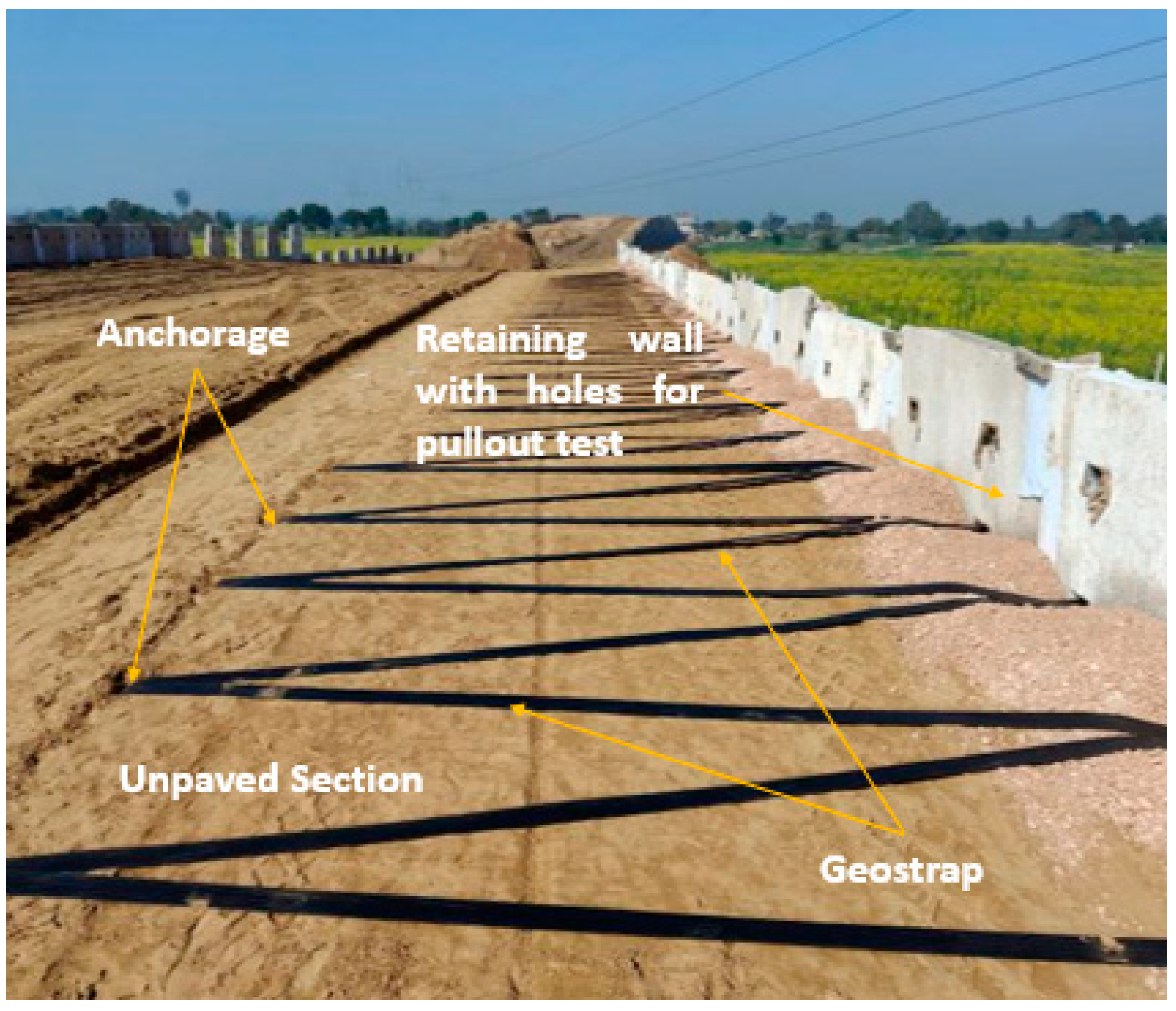
2. Materials and Methods
- τav = the average pullout resistance;
- Fmax = the maximum pullout force;
- B = the width of the reinforcement;
- L = the length of the reinforcement.

2.1. Design Tensile Strength of Geostraps
- Tult = the characteristic short-term tensile strength;
- γm = the partial material factor on the tensile strength of a geostrap;
- γn = the partial consequence factor to account for failure.
- The friction between the front end of the geostrap and the connecting edge of the pullout box is negligible.
- The parameters obtained from the lab are independent of the scale effect.
- The effective area method was used to determine the pulling force, and, accordingly, the displacement was measured at the front of the geostrap.
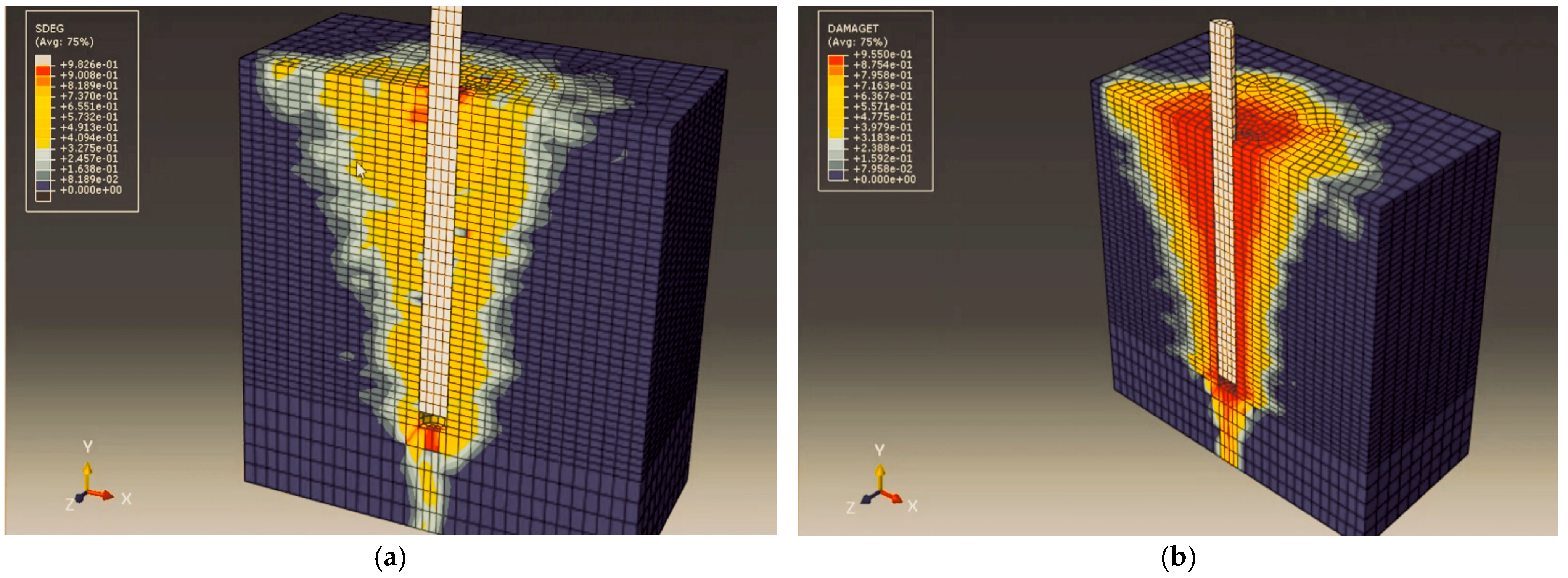
2.2. Numerical Simulation
3. Results
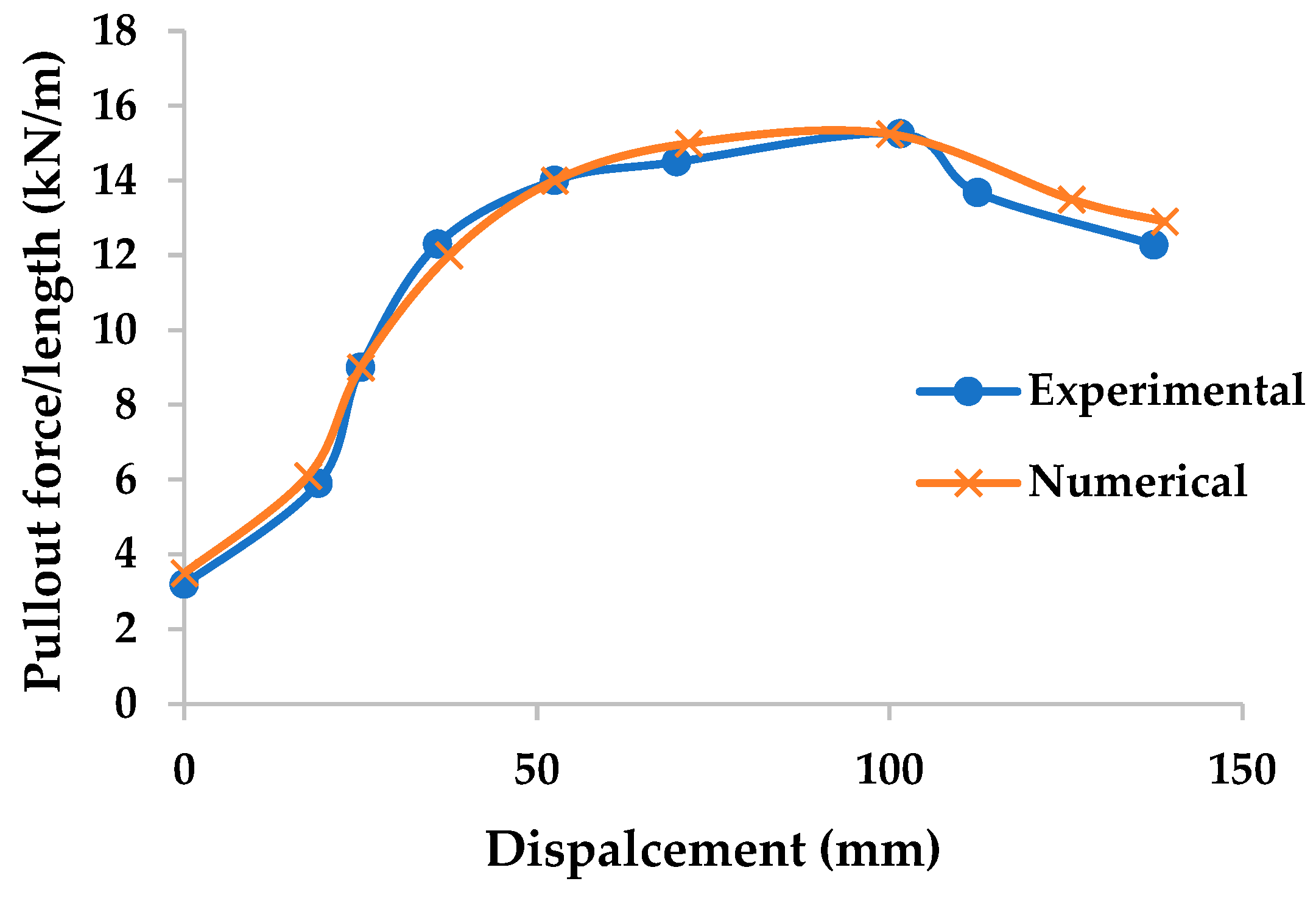
3.1. Convergence Test and Validation
- ts = the traction/pullout force;
- Ks = the stiffness in the shear plane;
- ∆s = the displacement.
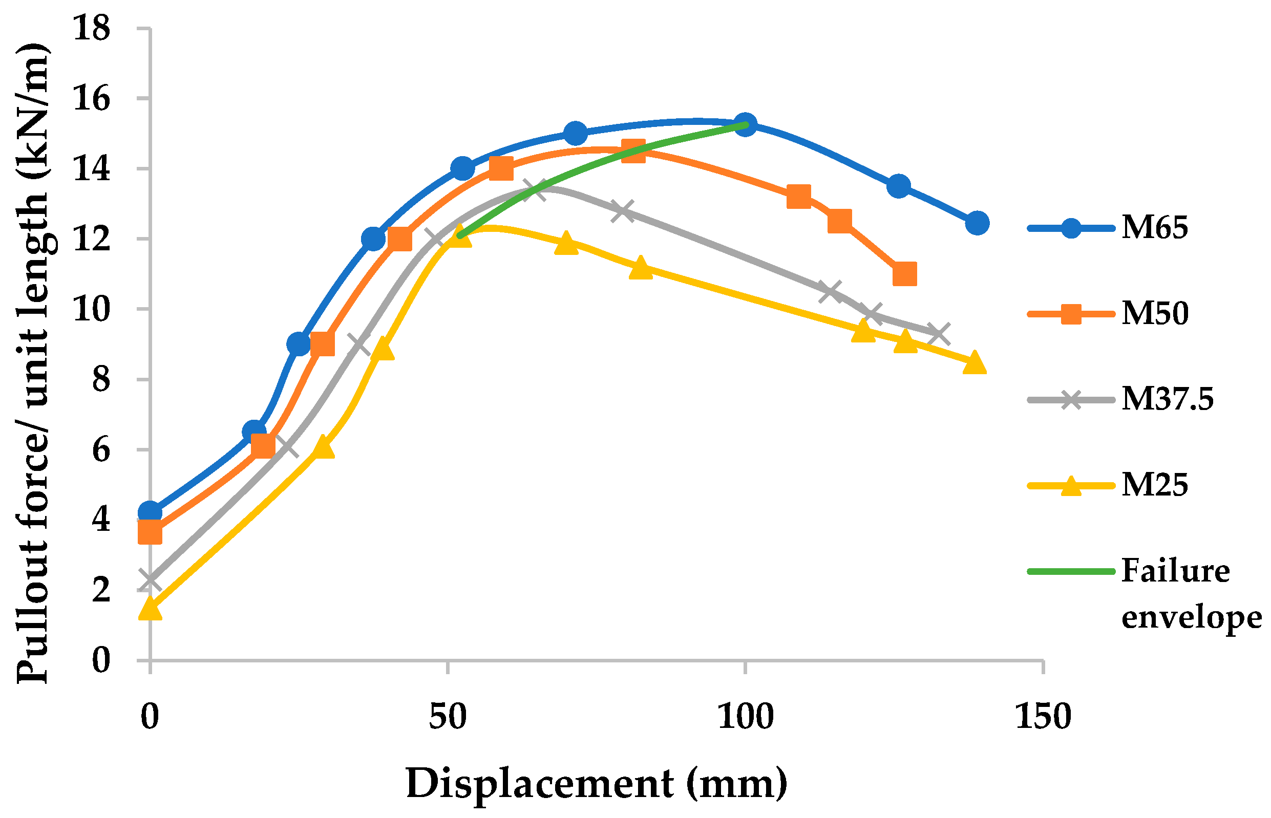
3.2. Comparison of Different Grades of Geostraps
3.3. Pullout Capacity: Geostrap vs. Geogrid
4. Discussion
5. Conclusions
Scope for Future Research
Author Contributions
Funding
Institutional Review Board Statement
Informed Consent Statement
Data Availability Statement
Acknowledgments
Conflicts of Interest
Abbreviations
| SP | Poorly Graded Sand |
| OMC | Optimum Moisture Content |
| FEA | Finite Element Analysis |
| GB | Gigabyte |
| RAM | Random Access Memory |
References
- Medina-Martinez, C.J.; Sandoval-Herazo, L.C.; Zamora-Castro, S.A.; Vivar-Ocampo, R.; Reyes-Gonzalez, D. Natural fibers: An alternative for the reinforcement of expansive soils. Sustainability 2022, 14, 9275. [Google Scholar] [CrossRef]
- Mohan, R.; Gupta, A.; Gaur, K. Utilization of bitumen, aggregate and wax with rubber tyre in a flexible pavement. In IOP Conference Series: Materials Science and Engineering, Proceedings of the International Conference on Advances in Civil Engineering (ICACE 2021), Guntur, India, 25–26 June 2021; IOP Publishing: Bristol, UK, 2021; Volume 1197, p. 12017. [Google Scholar] [CrossRef]
- Aamir, M.; Mahmood, Z.; Nisar, A.; Farid, A.; Ahmed Khan, T.; Abbas, M.; Ismaeel, M.; Shah, S.A.R.; Waseem, M. Performance evaluation of sustainable soil stabilization process using waste materials. Processes 2019, 7, 378. [Google Scholar] [CrossRef]
- Peças, P.; Carvalho, H.; Salman, H.; Leite, M. Natural fibre composites and their applications: A review. J. Compos. Sci. 2018, 2, 66. [Google Scholar] [CrossRef]
- Shastri, A.; Sánchez, M.; Gai, X.; Lee, M.Y.; Dewers, T. Mechanical behavior of frozen soils: Experimental investigation and numerical modeling. Comput. Geotech. 2021, 138, 104361. [Google Scholar] [CrossRef]
- Wang, Z.; Li, D.; Jia, Z.; Wang, Z.; Sun, Q. Experimental study on mechanical properties of highway subgrade in cold regions under different conditions. Appl. Sci. 2024, 14, 3547. [Google Scholar] [CrossRef]
- Demir, A.; Ok, B.; Sarici, T. Evaluation of rockfill stabilized-geosynthetics reinforced road base with repeated plate loading tests. Appl. Sci. 2024, 14, 3042. [Google Scholar] [CrossRef]
- Wu, D. Ride Comfort Prediction on Urban Road Using Discrete Pavement Roughness Index. Appl. Sci. 2024, 14, 3108. [Google Scholar] [CrossRef]
- Chen, C.; Zhang, G.; Zornberg, J.G.; Morsy, A.M.; Zhu, S.; Zhao, H. Interface behaviour of tensioned bars embedded in cement-soil mixtures. Constr. Build. Mater. 2018, 186, 840–853. [Google Scholar] [CrossRef]
- Koerner, R.M. Designing with Geosynthetics; Xlibris Corporation: Bloomington, IN, USA, 2012; Volume 1. [Google Scholar]
- Shukla, S.K. Geosynthetics and Their Applications; Springer: Berlin/Heidelberg, Germany; Thomas Telford: London, UK, 2017. [Google Scholar]
- Carlos, D.M.; Daniela, R.; Catarina, M.; Joaquim, M.; Margarida, P.L. Potential Application of Natural Fibres for the Reinforcement of Unpaved Forest Roads—Response after RL-CBR Tests. Appl. Sci. 2024, 14, 1006. [Google Scholar] [CrossRef]
- Rad, H.T.; Jalali, F.M.; Gheibi, M.; Khaksar, R.Y.; Annuk, A.; Moezzi, R. Enhancing Load-Bearing Capacity of Weak Soils Using Geosynthetics: A Finite Element Analysis. Mining 2024, 4, 777–805. [Google Scholar] [CrossRef]
- Altay, G.; Kayadelen, C.; Taşkıran, T.; Kaya, Y.Z. A laboratory study on pullout resistance of geogrid in clay soil. Measurement 2019, 139, 301–307. [Google Scholar]
- Palmeira, E.M. Soil-geosynthetic interaction: Modelling and analysis. Geotext. Geomembr. 2009, 27, 368–390. [Google Scholar] [CrossRef]
- Chen, Q.; Abu-Farsakh, M. Pullout resistance of geogrid reinforcements in granular soils under cyclic loading conditions. Geotext. Geomembr. 2016, 44, 482–491. [Google Scholar] [CrossRef]
- Shukla, S.K. An Introduction to Geosynthetic Engineering; CRC Press: Boca Raton, FL, USA, 2025. [Google Scholar]
- Boban, A.; Gaur, K.; Trivedi, A. Placement Depth and Layering Effect of Geogrid Reinforcement in Soft Subgrade Using Digital Static Cone Penetration Lab Test. In Proceedings of the International Conference on Sustainable Infrastructure: Innovation, Opportunities and Challenges, Mangalore, India, 23–24 April 2023; Springer Nature: Singapore, 2023; pp. 575–588. [Google Scholar] [CrossRef]
- Kumar, P.; Gaur, K.; Trivedi, A. Strength Analysis of Geotextile-Reinforced Subgrade. In Proceedings of the International Conference on Interdisciplinary Approaches in Civil Engineering for Sustainable Development, Bengaluru, India, 7–8 July 2023; Springer Nature: Singapore, 2023; pp. 263–276. [Google Scholar] [CrossRef]
- Grien, M.J.; Sankey, J.E. High capacity geostrap reinforcement for MSE structures. In New Horizons in Earth Reinforcement; CRC Press: Boca Raton, FL, USA, 2023; pp. 503–506. [Google Scholar]
- Rajagopal, K.; Krishnaswamy, N.R.; Latha, G.M. Behaviour of sand confined with single and multiple geocells. Geotextile Geomembr. 1999, 17, 171–181. [Google Scholar] [CrossRef]
- Zhou, H.; Wen, X. Model studies on geogrid-or geocell-reinforced sand cushion on soft soil. Geotextile Geomembr. 2008, 26, 231–238. [Google Scholar] [CrossRef]
- Demir, A.; Yildiz, A.; Laman, M.; Ornek, M. Experimental and numerical analyses of circularfooting on geogrid-reinforced granular fill underlain by soft clay. Acta Geotech. 2014, 9, 711–723. [Google Scholar] [CrossRef]
- Giroud, J.P.; Noiray, L. Geotextile-reinforced unpaved road design. J. Geotech. Eng. Div. ASCE 1981, 107, 1233–1254. [Google Scholar] [CrossRef]
- Wang, Y.; Yang, G.; Wang, L.; Li, X.; Jiao, G. Experimental Study on Reinforcement Properties of Tension-Resistant Reinforced Soil Retaining Wall. Buildings 2024, 14, 2951. [Google Scholar] [CrossRef]
- Esmaili, D.; Kianoosh, H.; Miller, G.A. Influence of matric suction on geotextile reinforcement-marginal soil interface strength. Geotext. Geomembr. 2014, 42, 139–153. [Google Scholar] [CrossRef]
- Koseki, J. Use of geosynthetics to improve seismic performance of earth structures. Geotext. Geomembr. 2012, 34, 51–68. [Google Scholar] [CrossRef]
- IS 2720 (Part 4); Methods of Test for Soils—Grain Size Analysis. Bureau of Indian Standards: New Delhi, India, 1985.
- IS 2720 (Part 8); Methods of Test for Soils—Determination of Water Content–Dry Density Relation Using Heavy Compaction. Bureau of Indian Standards: New Delhi, India, 1983.
- IS 2720 (Part 16); Methods of Test for Soils—Laboratory Determination of CBR. Bureau of Indian Standards: New Delhi, India, 1987.
- IS 2720 (Part 13); Methods of Test for Soils—Direct Shear Test. Bureau of Indian Standards: New Delhi, India, 1986.
- ASTM D6637; Standard Test Method for Determining Tensile Properties of Geogrids by the Single or Multi-Rib Tensile Method. ASTM International: West Conshohocken, PA, USA, 2023.
- Ochiai, H.; Jun, O.; Shigenori, H.; Takao, H. The pullout resistance of geogrids in reinforced soil. Geotext. Geomembr. 1996, 14, 19–42. [Google Scholar] [CrossRef]
- Indian Roads Congress (IRC). IRC:SP:59—Guidelines for Use of Geosynthetics in Road Pavements and Associated Works; Indian Roads Congress: New Delhi, India, 2019. [Google Scholar]
- GEO. Guide to Reinforced Fill Structures and Slope Design (Geoguide 6); Geotechnical Engineering Office, Civil Engineering and Development Department, HKSAR Government: Hong Kong, China, 2022; Volume 218. Available online: https://www.cedd.gov.hk/eng/publications/geo/geoguides/geo-g6/index.html (accessed on 10 June 2025).
- Leonardi, G.; Lo Bosco, D.; Palamara, R.; Suraci, F. Finite element analysis of geogrid-stabilised unpaved roads. Sustainability 2020, 12, 1929. [Google Scholar] [CrossRef]
- Kalyanshetti, M.G.; Halkude, S.A.; Magdum, D.A.; Patil, K.S. Estimation of modulus of elasticity of sand using plate load test. Am. J. Eng. Res. 2015, 4, 244–249. [Google Scholar]
- Civil Engineering and Development Department (CEDD). Available online: https://www.cedd.gov.hk/filemanager/eng/content_605/RF3_2023_GeoStrap%205.pdf (accessed on 20 June 2025).


| Geomaterial | Properties | Testing | Value |
|---|---|---|---|
| Soil | Classification | IS 2720 (Part 4) a | SP |
| OMC (%) | IS 2720 (Part 8) b | 11.6 | |
| MDD (g cc−1) | IS 2720 (Part 8) b | 1.853 | |
| CBR (%) | IS 2720 (Part 16) c | 16.28 | |
| Angle of internal friction, Φ (°) | IS 2720 (Part 13) d | 33 | |
| Geostrap (grade M65) | Width (mm) | Vernier Caliper | 91 |
| Thickness (mm) | Micrometer | 1.8 | |
| Ultimate tensile strength, UTS (kN) | ASTMD-6637 e (Method A) | 64.14 | |
| Elongation at UTS (%) | ASTMD-6637 e (Method A) | 9.45 |
| Geostrap Grade | Mass per Unit Length (g/m) | Characteristic Short-Term Tensile Strength (kN/m) | Partial Material Factor, γm | Partial Consequence Factor γn |
|---|---|---|---|---|
| M25 | 103 | 25 | 2.50 | 1.0 |
| M37.5 | 111 | 37.5 | 2.43 | 1.0 |
| M50 | 138 | 50 | 2.38 | 1.0 |
| M65 | 179 | 65 | 2.36 | 1.0 |
| Material | Element Type | Thickness (m) | Placement Depth (m) | E (MPa) | ν |
|---|---|---|---|---|---|
| Subgrade | Solid | 0.5 | - | E = 40 a | 0.3 |
| Geostrap | Solid | 0.01 | 0.150 | Eg = 65 b | 0.42 |
| Mesh Size | Meshed Subgrade | Stress at Point A | Simulation Time |
|---|---|---|---|
| 0.015 |  | 7.8119 | 3 h 40 m |
| 0.020 | 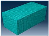 | 7.8117 | 2 h 38 m |
| 0.025 |  | 7.8105 | 1 h 20 m |
| 0.030 | 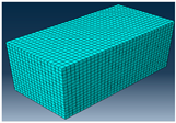 | 7.7941 | 40 m |
| Geostrap Grade | Maximum Pullout Strength (kN/m2) | Application Area | Soil Conditions | Remarks |
|---|---|---|---|---|
| M25 | 12.1 | Landscaping fill, shallow slope stabilisation | Well-compacted, non-cohesive to moderately cohesive soils | Suitable for non-critical zones with low shear stress and minimal surcharge |
| M37.5 | 13.4 | Light traffic embankments, shallow foundation beds | Moderately firm soils with moderate moisture | Improves bearing and settlement resistance in lightly loaded zones |
| M50 | 14.5 | Reinforced slopes, pavement subgrade improvement | Soft to firm soils with variable moisture | Common for road-base stabilisation and slopes under moderate traffic loads |
| M65 | 15.25 | Embankments over soft soils, seismic reinforcement | Weak, compressible, or aggressive soils | Preferred in critical areas with high loads; long-term performance is required |
| Type of Geosynthetics | Initial Pullout Strength (kN/m) | Initial Strength Difference (%) | Final Pullout Strength (kN/m) | Final Strength Difference (%) | Final Pullout Displacement (mm) | Application Area | Remarks |
|---|---|---|---|---|---|---|---|
| Geostrap M65 | 18 | 20 | 49 | 8.16 | 40 | Embankments over soft soils, seismic reinforcement, etc. | High initial pullout strength suitable for low-volume roads |
| Geogrid | 15 | 53 | 60 | Pavements on weak subgrade, erosion control, etc. | High total pullout strength suitable for high-volume roads |
Disclaimer/Publisher’s Note: The statements, opinions and data contained in all publications are solely those of the individual author(s) and contributor(s) and not of MDPI and/or the editor(s). MDPI and/or the editor(s) disclaim responsibility for any injury to people or property resulting from any ideas, methods, instructions or products referred to in the content. |
© 2025 by the authors. Licensee MDPI, Basel, Switzerland. This article is an open access article distributed under the terms and conditions of the Creative Commons Attribution (CC BY) license (https://creativecommons.org/licenses/by/4.0/).
Share and Cite
Gaur, K.; Trivedi, A.; Shukla, S.K. A Comparative Study of the Pullout Strength of Geostraps and Geogrids in Reinforced Soil. Appl. Sci. 2025, 15, 7715. https://doi.org/10.3390/app15147715
Gaur K, Trivedi A, Shukla SK. A Comparative Study of the Pullout Strength of Geostraps and Geogrids in Reinforced Soil. Applied Sciences. 2025; 15(14):7715. https://doi.org/10.3390/app15147715
Chicago/Turabian StyleGaur, Kshitij, Ashutosh Trivedi, and Sanjay Kumar Shukla. 2025. "A Comparative Study of the Pullout Strength of Geostraps and Geogrids in Reinforced Soil" Applied Sciences 15, no. 14: 7715. https://doi.org/10.3390/app15147715
APA StyleGaur, K., Trivedi, A., & Shukla, S. K. (2025). A Comparative Study of the Pullout Strength of Geostraps and Geogrids in Reinforced Soil. Applied Sciences, 15(14), 7715. https://doi.org/10.3390/app15147715