Abstract
Material defects resulting from manufacturing and processing can significantly affect material properties. Voids and dislocations are material defects considered in this study, in which a numerical solution of the 3D stress field of a dislocation line (infinite or finite) outside a cylindrical void (either parallel to the cylinder axis or not) is developed using the collocation point method. The collocation point method is utilized to solve ordinary differential equations, partial differential equations, differential-algebraic equations, and integral equations by enforcing the solution at a set of spatial collocation points. Analytical solutions for such three-dimensional (3D) problems, e.g., a dislocation line or segment near an internal void of any shape, were not found. Therefore, a numerical solution for this problem has been constructed in this paper. The numerical solution developed is verified using an existing two-dimensional analytical solution. The numerical results and the 2D analytical solution are in perfect agreement as long as the cylindrical void is sufficiently long and the Saint-Venant’s principle is followed.
1. Introduction
Material defects usually arise during manufacturing, processing, or even in service conditions due to environmental factors. Furthermore, defects can be generated when materials are subjected to mechanical loading. The main defects that commonly exist in materials are point defects, line defects, surface defects, and volume defects. Cylindrical voids (volume defects) and dislocations (line defects) are two types of material defects considered in this study. The formation of cylindrical voids can result from several different causes. Specifically, cylindrical voids can form in compressible hyperelastic materials through a cavitation process, which is triggered when the applied radial stretch reaches a critical value [1]. In the additive manufacturing (AM) process or 3D printing, undesirable voids, such as interlayer voids, can be produced by incomplete material filling within part layers [2,3]. Additionally, voids can be generated from the extrusion process in additive manufacturing. Movement of the printhead and the speed of printing are driving factors that affect a void’s shape. For instance, a cylindrical void forms if the printhead follows a circular path that does not fuse properly with the material beneath. In casting, improper mold filling or cooling can trap gases or cause shrinkage, especially in directional solidification, where voids align with the cooling gradient. Cylindrical voids, located along the axial direction, can be produced by continuous casting. Closure of these cylindrical voids by flat-die forging was investigated in [4,5] as these voids detrimentally affect material properties. The effects of voids on mechanical properties of materials are well documented, such as in [6,7].
A dislocation is a type of crystallographic defect in a material, specifically a line defect, where an extra half-plane of atoms is inserted into the crystal structure (edge dislocation) and the crystal layers are sheared in such a way that the atoms form a spiral ramp around the dislocation line (screw dislocation) [8,9]. Much research has been devoted to investigating dislocation problems regarding the scale of a material as well as its type and geometry.
Research on developing analytical solutions for elastic fields of dislocations has been performed and presented in previous literature. Some research has focused on the elastic fields of an infinite dislocation [10,11,12], the stress fields of a prismatic rectangular dislocation loop [13], and the displacement fields of a rectangular loop [14] in an infinite isotropic material. As for studies involving dislocations near a traction-free surface, a correction term is added to calculate the total stress fields of the dislocations in order to ensure zero-traction conditions on the free surface. Analytical solutions for elastic fields of dislocations near a planar or flat free surface have been provided in previous studies [15,16,17,18]. In addition, a stress field due to an infinite edge dislocation outside, and parallel to, an infinite cylinder in an infinite isotropic material is presented analytically or in exact form in [19]. Nonetheless, analytical solutions for the stress field of dislocation segments (of finite length, and not just infinite, and of any orientation with respect to the void) near a finite-sized cylindrical void or any other void shape have not been identified. Hence, numerical solutions for such problems need to be developed and applied.
The collocation point method is one of the main numerical methods used to resolve traction-free surface problems. The employment of a collocation point method to treat zero-traction boundaries in three-dimensional discrete dislocation dynamics was carried out by [20,21,22]. In these studies [20,21,22], coordinate transformation was involved, as the correction terms to satisfy the traction-free boundary conditions were developed using local coordinate systems, which needed to be transformed back into a global coordinate system in order to calculate the total stress fields of a dislocation segment near traction-free boundaries. Recently, a numerical solution capable of computing all stresses due to a dislocation source and the correction terms using a global coordinate system without the need for second-order tensor transformations was developed and demonstrated in [23,24].
In this study, a numerical solution for the stress field of a dislocation line (segment/finite-length or infinite and at any spatial orientation) outside a cylindrical void (of any length and can be a non-cylindrical shape as well) is developed using the collocation point method. All the stress computations in this study are carried out in a global coordinate system, hence no tedious first-rank or second-rank tensor transformations are involved. The numerical solution developed herein is then compared with the analytical solution derived from [19] for verification purposes. Specifically, the cylinder length is increased as much as possible and the dislocation is kept parallel to the cylinder axis to match the analytical solution of the 2D problem. Additionally, the dislocation source, or the driving force in the numerical solution, needs to be an infinite dislocation in an infinite isotropic material in order to make a comparison with the 2D analytical solution. The verification process will be elaborated on in more detail in Section 4.
2. A Numerical Solution Developed Using the Collocation Point Method
2.1. A Dislocation near a Cubic Void
The aim of the collocation point method is to solve ordinary differential equations, partial differential equations, differential-algebraic equations, and integral equations by enforcing the solution at a set of collocation points [25]. Figure 1 shows a dislocation line of finite length, or a Frank–Read dislocation source, near an internal cubic void. In this case, the known stress field due to a finite dislocation segment (and provided for an infinite homogeneous material) [26] will violate the traction-free or zero-traction boundary condition of such planar or flat void surfaces. This stress-traction condition can be stated at every collocation point on the free surface as:
where is the state of stress at the collocation point, and is the unit normal vector of a plane passing through the surface collocation point in space (where the stress-traction vector is determined). The last vector equation translates or equates to three scalar equations: . Equation (1) also translates, for every free surface point in this case, to:
where represents the direction of the unit normal vector, and (,0,0), (), or () are the unit normal vectors pointing in the x-axis, y-axis, or z-axis, respectively. When , Equation (2) becomes:
which is the zero stress-traction condition, or free surface condition, on the top surface in Figure 1.
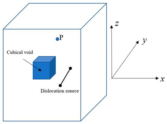
Figure 1.
A dislocation line segment near a cubic void inside a cubic crystal. Point P is an arbitrary field point in the material/crystal.
Analytical solutions for such a problem, i.e., a dislocation segment, or a finite-length dislocation line, near an internal void have not been found before. Therefore, one must rely on numerical solutions or methods, such as the collocation point method. The collocation point method starts with discretizing the free surfaces of the cubic void shown in Figure 1 by using a mesh (with rectangular elements or triangular elements): see Figure 2. In this scenario, the collocation points are the centers of each mesh element. To satisfy the zero-traction condition on the free surfaces, an extra source of self-equilibrated stress is needed to annul the unphysical traction stemming from the dislocation segment (which is given for an infinite medium). Each element is considered as a Volterra prismatic dislocation loop (a rectangular or triangular dislocation loop). Dislocation loops are chosen as the surface elements because each dislocation loop is a self-equilibrated source of stress. The sum of the stress fields of the dislocation loops or the surface elements is the complementary solution, while the stress field arising from the real dislocation line/source is the original solution; the residual is the difference between these two solutions. The residual is enforced to be zero at the collocation points, i.e., by solving the system of Equations (4) or (11) in the next sub-section.

Figure 2.
Cubic void surface meshed with rectangular elements or triangular elements.
As mentioned earlier in this section, zero-traction conditions need to be enforced on the free surfaces. Let us focus on one of the planar free surfaces, as shown in Figure 3. According to Equation (3), . These three stress components are annulled on a set of collocation points representing the centers of the dislocation loops padding the surface. Mathematically, the problem can be expressed as follows:
where is the stress component of loop evaluated at collocation point or at the center of loop . Furthermore, is the stress component of segment calculated at point . Stress at any field point for a rectangular dislocation loop in the global coordinate system is provided in the following equation:
where is the stress due to segment AB of the dislocation loop ABCD, and so forth.
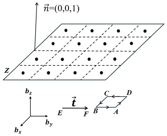
Figure 3.
A dislocation segment , with a line sense vector , beneath a free surface. Surface Z is meshed by rectangular elements representing dislocation loops. The inset shows one of the rectangular loops ABCD with Burgers vector components , and . The centers of the elements are the collocation points.
One can analyze the stress solution of a dislocation segment [26] and find that the stress solution is linear with respect to the Burgers vector components , , and . This allows the following equation to be inserted into Equation (4):
where is the stress component for loop j (or dislocation j in general) at collocation point , is the x-component of the Burgers vector for the generally prismatic dislocation loop j, and is the kernel term associated with the x-component of the Burgers vector and evaluated at collocation point . The kernels , and can be derived from the work of Devincre [26], for a dislocation line segment, and are clearly demonstrated in [24]. Hence, derivation of the kernel terms is not shown here for brevity.
Inserting Equation (6) into Equation (4), the following system of equations ensues:
The above system represents a system of linear algebraic equations. The unknowns in this system of equations are the Burgers vector components of the N loops. Equation (7) can be expanded and written as:
Here, the size of the kernel matrix is . Once the Burgers vectors are solved, that is obtained, for all surface loops, the stress field can be computed at any point in the crystal (point P in Figure 1). The stress solution at field point P due to a dislocation near a cubic void can be expressed as:
where is the stress due to a real dislocation at field P in the crystal and is the stress contribution by the dislocation loop at point . This is performed for each surface of the cube.
2.2. A Dislocation near a Cylindrical Void
The above problem formulation was developed for a void with planar/flat surfaces that are perpendicular to the three coordinate axes. If a void has curved surfaces instead, it can be a cylindrical void or a spherical void. This study focuses on a dislocation segment, or finite-length dislocation line, near a cylindrical void, as shown in Figure 4. The analytical solution for the stress field of this 3D problem does not exist, although the analytical solution of a 2D problem, i.e., the stress field arising from an infinite dislocation line near an infinitely-long cylindrical void, is presented in [19], where the dislocation line and cylinder axis are parallel to each other. Hence, the collocation method will be utilized to develop the numerical solution for the 3D problem. For the curved surface, the mesh is typically made up of structured or unstructured triangles. In this study, uniform or structured rectangular and triangular elements are used to mesh the cylinder for convenience. Figure 5 shows a cylindrical void meshed with triangular and rectangular elements. Figure 6 is the frontal view of the meshed cylinders in Figure 5.
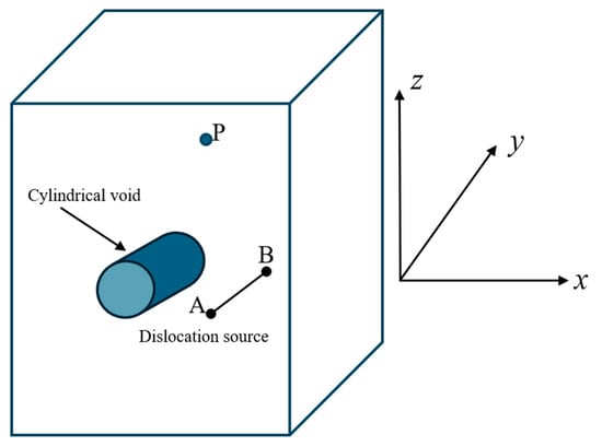
Figure 4.
A dislocation line segment near a cylindrical void in a cubic crystal. Point P is an arbitrary field point in the material/crystal.

Figure 5.
A cylindrical void meshed with (a) triangular elements or (b) rectangular elements. Each element represents a dislocation loop, and the line sense of the dislocation is shown with the arrows around the loop.
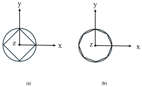
Figure 6.
Side view of the cylindrical void with (a) coarser and (b) denser meshes (note: the elements only increase along the perimeter of the cylinder and not along its length).
For the problem depicted in Figure 4, the mathematical formulation of the problem is not exactly the same as the one for the cubic void. For example, Equation (1) still holds for any collocation point (the center points of the mesh elements, i.e., generally prismatic dislocation loops). However, Equation (2) no longer holds and instead needs to be replaced by the following equation:
Equation (10) can be expressed for this general free-surface problem as:
where is the stress-traction component for loop j calculated at collocation point . Furthermore, is the stress-traction component of dislocation segment evaluated at collocation point . Here, N is the total number of loops or elements in the mesh.
However, from continuum mechanics, the stress-traction components at a field point in space/material are related to the stress tensor components at the same point and to the components of a unit normal vector of a plane (the plane defining the traction) passing through the point as such:
Expanding Equation (12), Equation (11) can be rewritten as:
Now, Equation (6) needs to be substituted for the stresses in Equation (13). This will generate a total of 9 terms inside the sum of each equation:
These 9 terms in each equation need to be collected for , , and . In other words, the Burgers vector components in Equation (14) need to be factored out as follows:
After this, a similar system of equations, in construct, to the system of Equation (8) can be generated (Note: ):
Once this latest system of equations is solved, the Burgers vectors of all surface loops are obtained and then the stress solution of a dislocation line near a cylindrical void can be properly computed at any material field point using Equation (9).
3. An Analytical Solution
An analytical solution for the stress field arising from an infinite edge dislocation outside a cylindrical inclusion, and parallel to its axis, is provided by Hills et al. [19,27]. As shown in Figure 7, the dislocation is in region 1 or material 1 at position (, 0), and the radius of the cylindrical inclusion (material 2 or region 2) is . In this case, the stress field due to an edge dislocation, () in region 1, can be derived from the Airy stress functions presented in [27]:
where represents the stress component due to the dislocation in region 1, is the shear modulus of the region 1, is the Kolosov’s constant for in-plane strain, and are the influence functions documented in [19,27]. When the elastic constants of material 2 or region 2 (cylindrical inclusion) are equal to zero (representing a void), the stress solution developed by Hills et al. [19,27] can be idealized to the stress field of an infinite edge dislocation near an infinitely long cylindrical void, and the following parameters can be simplified to:
where is the Poisson’s ratio of region 2, is the Poisson’s ratio of region 1, and and are Dundurs’ parameters.
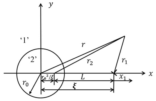
Figure 7.
An edge dislocation outside a cylindrical inclusion [26].
4. Results: Verification of the Numerical Solution
To verify the numerical solution developed in this study, the authors compared the numerical results with the analytical solution presented in the last section. The numerical solution developed in this study is inherently for a 3D problem, i.e., the stress solution of an edge or screw or mixed dislocation (of any length) near a cylindrical void or any void of any shape. On the contrary, the analytical solution is developed for a 2D problem, i.e., the stress solution of an infinite edge dislocation near an infinitely long cylindrical void or a circular hole.
The length of the cylindrical void in our numerical solution needs to be close to infinite or relatively infinite compared with the radius of the cylinder, in order to make the comparison between the numerical results and the 2D analytical solution. Additionally, an infinite dislocation should be used as the real dislocation or the driving force in our numerical solution to match the analytical results.
Before discussing and verifying the results, some parameters are specified and symbolized for simplicity, as follows: Shear modulus: G; Poisson’s ratio: ; Burger’s vector: ; radius of the cylinder: ; length of the cylinder: l; location of the dislocation: ; coordinate of the cylinder’s center: (0, 0); distance between the right edge of the cylinder and the field points line along the y-axis, as shown in Figure 8: D; average spacing between the collocation points: q; and distance between the neighboring collocation points along the circumferential direction s, as shown in Figure 5.
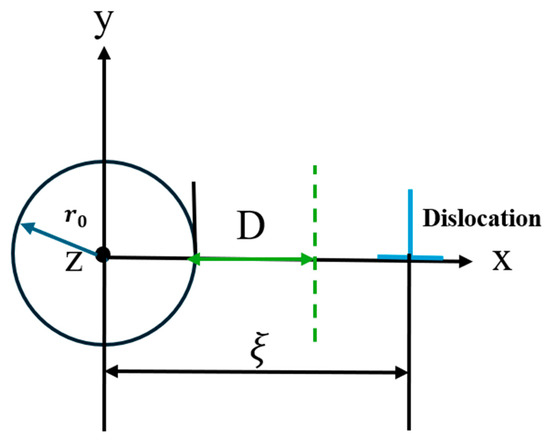
Figure 8.
Schematic figure for an infinite edge dislocation near a cylindrical hole with the radius .
On a separate note, the dimensional parameters , D, l, q, and s are all normalized by the magnitude of the Burger’s vector b, and the stress is normalized by the shear modulus. The purpose of normalization is to transform parameters and results at different scales to be on a similar scale, and to improve the generalization of the current numerical solution [28,29].
.
For the comparison plots, the stress field of a dislocation near an infinitely long cylindrical void is plotted on the xy-plane (z = 0) along a line parallel to the y-axis and shifted D distance away from the right edge of the cylinder along the x-axis; see the dashed green line in Figure 8. Defining the following parameters for plotting: G = 110 GPa, (elastic properties of copper [30]), , l = 1 million b, ; for the real dislocation, the infinite dislocation, or the driving force, is (1, 0, 0).
Figure 9 shows that the numerical solution approaches the analytical solution [19,27] as the number of rectangular dislocation loops padding the curved surface of the cylinder increases. In numerical methods, the solution is approximated by essentially piecewise functions over each element. More elements allow for a better approximation of the geometry and the numerical solution can change more precisely from one element to another. Furthermore, the spacing between the elements gets closer as the number of elements increases, resulting in a reduction in truncation errors and a more accurate numerical solution [25,31].
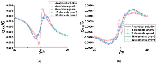
Figure 9.
Comparison plots between the analytical solution and numerical results (rectangular elements, D = 2b, , l = 1 million b, , for the real dislocation, the infinite dislocation or the driving force is (1, 0, 0)) (a) normalized (b) normalized ).
Figure 9 shows the results for field points along the line parallel to the y-axis and shifted D = 2b distance away from the right edge of the cylinder along the x-axis. In this case, the field points are close to the cylindrical void. Saint-Venant’s principle states that the elastic fields resulting from different but statically equivalent force distributions on a body are approximately the same far away from the loading points or these force distributions [32]. That being said, the stress field caused by the cylindrical void with different mesh densities should be the same if the field points are far away from the void. The purpose of the stress field induced by the dislocation loops meshing the surface of the void is to annul (at the free-surface collocation points) the stress field arising from the real dislocation, which is constant in this study; hence, the stress fields caused by the cylindrical void with different mesh densities should be statically equivalent. The critical distance to avoid any effect of the different but statically equivalent loads/force distributions should be equal to or greater than the average spacing between the collocation points (q) [23,24]. This—that is, the application of Saint-Venant’s principle—is shown clearly for meshes with 16 and 32 elements. The results shown in the plots of Figure 9 can also be shown by inversely varying the D for different q values (i.e., different rectangular mesh densities). According to Figure 10, the effect of cylindrical void meshing with different numbers of rectangular dislocation loops (i.e., with different stress fields that are statically equivalent) dies out when the distance D is greater than q. In other words, the critical distance D must be larger than q to ensure the accuracy of the numerical solution, which is consistent with statements in [23,24].
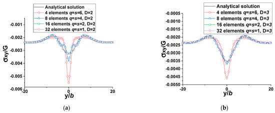
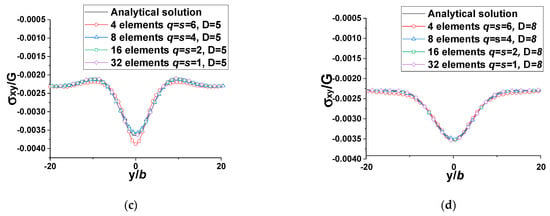
Figure 10.
Comparison plots between the analytical solution and numerical results for normalized (rectangular elements, , l = 1 million b, , for the real dislocation, the infinite dislocation or the driving force is (1, 0, 0)) (a) D = 2b (b) D = 3b (c) D = 5b (d) D = 8b).
It is important to note that the rectangular elements are increased along the circumferential direction (see Figure 5b and Figure 6), and all collocation points in this case are located on the xy-plane (z = 0). The average spacing between collocation points (q) for this uniform mesh is the same here as the distance between the collocation points (s) along the circumferential direction. For the triangular elements, q is much larger than s as the centers of the triangular dislocation loops/meshing elements, or the collocation points, are far away from the xy-plane, and the distance between the collocation points of two neighboring triangular elements (distance measured along the longitudinal direction or the length of the cylinder) is close to infinity for the almost infinite cylinder considered here (see Figure 5a and imagine the cylinder is infinitely long). Therefore, the critical distance D to ensure the accuracy of the numerical solution developed by the collocation point method is expected to be larger than the distance s between the collocation points along the circumferential direction. This is shown in Figure 11. Although triangular elements or triangular dislocation loops offer more flexibility for irregular shapes or curved surfaces, their centers or collocation points are far from the xy-plane and hence from the plotted field points. As the centers of the rectangular elements (or their collocation points) are all on the xy-plane (at z = 0), this provides a better numerical solution compared to the 2D analytical solution in this scenario. It should be recalled here that the stress field points are plotted on the xy-plane, z = 0. Figure 11 also shows that this issue can be overcome with distance D versus q by simply increasing the number of elements or the mesh density (i.e., by simply decreasing s).
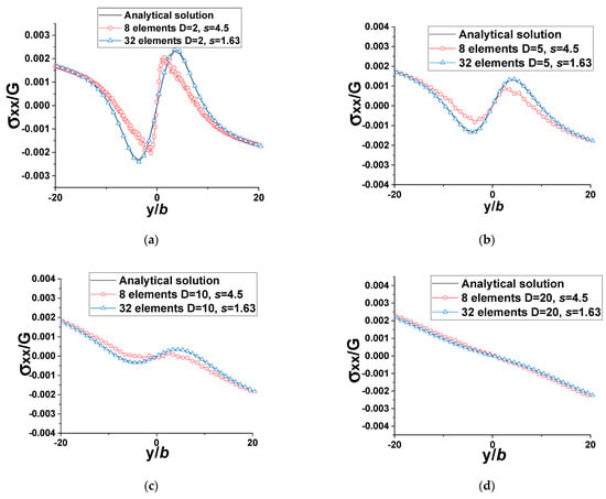
Figure 11.
Comparison plots between the analytical solution and numerical results for normalized (triangular elements, s = 4.5b or 1.63b, , l = 1 million b, q~l, , for the real dislocation, the infinite dislocation or the driving force is (1, 0, 0)) (a) D = 2b (b) D = 5b (c) D = 10b (d) D = 20b.
Before concluding this section, it is worth noting the effect of the length of the cylinder (l) on the numerical solution. In studies of the effects of mesh density and the critical distance D, l is maintained constant at 1 million b, which is a number close to infinity compared with the radius of the cylinder , in order to verify our numerical solution with the 2D analytical solution. In the investigation of the effects of l, 32 rectangular elements or rectangular dislocation loops are used to uniformly mesh the curved surface of the cylinder. All other dimensional parameters are kept unchanged. The stress fields are plotted on the xy-plane along the line parallel to the y-axis and shifted D = 2b distance away from the right edge of the cylinder along the x-axis. As shown in Figure 12, the mismatch between the numerical results and the 2D analytical solution diminishes as the length of the cylinder (l) increases. Eventually, the numerical solution and the analytical solution overlap as l approaches relative infinity (i.e., 1 million b) compared with . According to the Saint-Venant’s principle, the numerical solution should have matched the analytical solution as the distance D (D = 2b) is greater than the spacing between the neighboring collocation points (q = s = 1b). However, the length of the cylinder (l) is another key factor affecting the accuracy of the numerical solution. When l is too small, say l = 4b, the numerical result cannot match the analytical solution even though D is greater than q (see Figure 12), as the 2D analytical solution is for the stress field of an infinite edge dislocation outside an infinitely long cylindrical void. Conversely, the numerical solution and the analytical result are in perfect agreement when l is sufficiently large, as demonstrated in Figure 12.
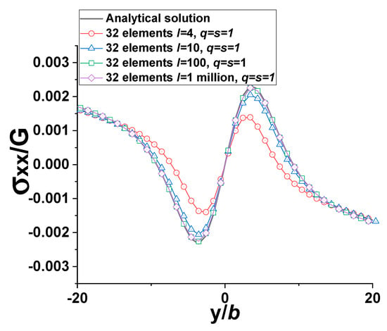
Figure 12.
Comparison plots between the analytical solution and numerical results for normalized (32 rectangular elements, D = 2b, q = s = 1b, , l = 1 million b, , for the real dislocation, the infinite dislocation or the driving force is (1, 0, 0)). This plot shows the effect of cylinder length on the stress results.
Overall, verification of the numerical solution developed by the collocation point method for the stress fields of a dislocation near a cylindrical void has been achieved. The numerical solution and the 2D analytical solution match without any deviation as long as the critical distance D is larger than the average spacing between collocation points (q), and the cylindrical void is infinitely long compared with the radius of the cylinder . For the general 3D numerical solution, the real dislocation or the driving force can be any type of dislocation (e.g., a dislocation loop or a dislocation segment), and the cylindrical void can be infinitely long or of finite length or of any shape and not just cylindrical. To ensure the accuracy of the 3D numerical solution, the mesh needs to be sufficiently dense and the Saint-Venant’s principle is applied. The authors are not familiar with any fully-3D analytical dislocation-void problems with which to directly compare these results, except for the 2D analytical solution provided above. Theory of elasticity-based dislocation solutions are limited to field points beyond a core radius (usually between b and 4b [8]) of a dislocation (whether a crystal dislocation or a mesh dislocation). The 3D numerical solution can be implemented into three-dimensional dislocation dynamics codes for dynamic simulations to investigate the interaction between a dislocation source and a void of any shape, and the mechanical plastic properties (e.g., the flow stress) of materials with such voids.
5. Conclusions
In this study, a numerical solution for stress fields of a dislocation outside a finite cylindrical void is developed using the collocation point method. The numerical solution has been verified by comparing it with the 2D analytical solution.
According to the comparison figures, the numerical solution and the 2D analytical solution match perfectly as long as the critical distance is greater than the average spacing between the collocation points. Furthermore, the cylinder needs to be infinitely long compared with the radius of the cylinder. For the general 3D numerical solution, the real dislocation or the driving force can be any type of dislocation (e.g., a dislocation loop, a dislocation segment, or an infinite dislocation), and the cylindrical void can be infinitely long or of finite length. To ensure the accuracy of the 3D numerical solution, the mesh needs to be sufficiently dense and the Saint-Venant’s principle should be satisfied. The 3D numerical solution developed herein can be applied to the three-dimensional dislocation dynamics codes for dynamic simulations to investigate the interaction between the dislocation source and the cylindrical void, as well as to shed more light on the mechanical properties of materials with such voids.
Author Contributions
Conceptualization, T.K.; formal analysis, L.L. and T.K.; investigation, L.L.; writing—original draft, L.L.; writing—review and editing, T.K.; supervision, T.K. All authors have read and agreed to the published version of the manuscript.
Funding
This research received no external funding.
Institutional Review Board Statement
Not applicable.
Informed Consent Statement
Not applicable.
Data Availability Statement
The original contributions presented in this study are included in the article. Further inquiries can be directed to the corresponding author.
Conflicts of Interest
The authors declare no conflicts of interest.
References
- Biwa, S. Critical stretch for formation of a cylindrical void in a compressible hyperelastic material. Int. J. Mech. Sci. 1995, 30, 899–914. [Google Scholar] [CrossRef]
- Sun, X.; Mazur, M.; Cheng, C.-T. A review of void reduction strategies in material extrusion-based additive manufacturing. Addit. Manuf. 2023, 67, 103463. [Google Scholar] [CrossRef]
- Ngo, T.D.; Kashani, A.; Imbalzano, G.; Nguyen, K.T.Q.; Hui, D. Additive manufacturing (3D printing): A review of materials, methods, applications and challenges. Compos. Part B Eng. 2018, 143, 172–196. [Google Scholar] [CrossRef]
- Park, J.-J. Finite-element analysis of cylindrical-void closure by flat-die forging. ISIJ Int. 2013, 53, 1420–1426. [Google Scholar] [CrossRef]
- Park, J.-J. Prediction of void closure in metal forming: One cylindrical through-hole. ISIJ Int. 2018, 58, 1102–1107. [Google Scholar] [CrossRef]
- Ji, S. Porosity dependence of mechanical properties of solid materials. J. Mater. Sci. 2006, 41, 1757–1768. [Google Scholar]
- Tronvoll, S.A.; Welo, T.; Elverum, C.W. The effects of voids on structural properties of fused deposition modelled parts: A probabilistic approach. Int. J. Adv. Manuf. Technol. 2018, 97, 3607–3618. [Google Scholar]
- Hull, D.; Bacon, D.J. Introduction to Dislocations, 5th ed.; Butterworth-Heinemann: New York, NY, USA, 2011. [Google Scholar]
- Hirth, J.P.; Lothe, J. Theory of Dislocations, 5th ed.; Krieger Publishing Company: Malabar, FL, USA, 1982. [Google Scholar]
- Lubarda, V.A.; Kouris, D.A. Stress fields due to dislocation walls in infinite and semi-infinite bodies. Int. J. Solids Struct. 1996, 23, 169–189. [Google Scholar] [CrossRef]
- Pan, E. Dislocation in an infinite poroelastic medium. Acta Mech. 1991, 87, 105–115. [Google Scholar]
- Weertman, J.; Weertman, J.R. Elementary Dislocation Theory; Oxford University Press: Oxford, UK, 1992. [Google Scholar]
- Verecký, Š.; Kratochvíl, J.; Kroupa, F. The stress field of rectangular prismatic dislocation loops. Phys. Status Solidi A 2002, 191, 418–426. [Google Scholar]
- Khraishi, T.A.; Zbib, H.M. The displacement field of a rectangular Volterra dislocation loop. Phil. Mag. Lett. 2002, 82, 265–277. [Google Scholar]
- Yoffe, E.H. A Dislocation at a Free Surface. Philos. Mag. 1961, 6, 1147–1155. [Google Scholar] [CrossRef]
- Baštecká, J. Interaction of dislocation loop with free surface. Českoslov. Fyzikální Žurnál B 1964, 14, 430–442. [Google Scholar] [CrossRef]
- Groves, P.P.; Bacon, D.J. The dislocation loop near a free surface. Philos. Mag. 1970, 22, 83–91. [Google Scholar] [CrossRef]
- Shima, H.; Umeno, Y.; Sumigawa, T. Analytic formulation of elastic field around edge dislocation adjacent to slanted free surface. R. Soc. Open Sci. 2022, 9, 220151. [Google Scholar] [CrossRef]
- Hills, D.A.; Kelly, P.A.; Dai, D.N.; Korsunsky, A.M. Solution of Crack Problems: The Distributed Dislocation Technique; Springer: Dordrecht, The Netherlands, 1996. [Google Scholar] [CrossRef]
- Khraishi, T.A.; Zbib, H.M. Dislocation dynamics simulations of the interaction between a short rigid fiber and a glide circular dislocation pile-up. Comput. Mater. Sci. 2002, 24, 310–322. [Google Scholar] [CrossRef]
- Khraishi, T.A.; Zbib, H.M. Free-surface effects in 3D dislocation dynamics: Formulation and modeling. J. Eng. Mater. Technol. 2002, 124, 342–351. [Google Scholar] [CrossRef]
- Yan, L.; Khraishi, T.A.; Shen, Y.-L.; Horstemeyer, M.F. A distributed dislocation method for treating free-surface image stresses in three-dimensional dislocation dynamics simulations. Model. Simul. Mater. Sci. Eng. 2004, 12, S289–S301. [Google Scholar] [CrossRef]
- Siddique, A.B.; Khraishi, T. Numerical methodology for treating static and dynamic dislocation problems near a free surface. J. Phys. Commun. 2020, 4, 055005. [Google Scholar] [CrossRef]
- Siddique, A.B.; Khraishi, T. A mesh-independent brute-force approach for traction-free corrections in dislocation problems. Model. Numer. Simul. Mater. Sci. 2021, 11, 1–18. [Google Scholar]
- Ascher, U.M.; Petzold, L.R. Computer Methods for Ordinary Differential Equations and Differential-Algebraic Equations; Society for Industrial and Applied Mathematics: Philadelphia, PA, USA, 1998; ISBN 978-0-89871-412-8. [Google Scholar]
- Devincre, B. Three dimensional stress field expressions for straight dislocation segments. Solid State Commun. 1995, 93, 875–878. [Google Scholar] [CrossRef]
- Dundurs, J.; Mura, T. Interaction between an edge dislocation and a circular inclusion. J. Mech. Phys. Solids 1964, 12, 177–189. [Google Scholar]
- Huang, L.; Qin, J.; Zhou, Y.; Zhu, F.; Liu, L.; Shao, L. Normalization techniques in training DNNs: Methodology, analysis and application. IEEE Trans. Pattern Anal. Mach. Intell. 2023, 45, 10173–10196. [Google Scholar] [CrossRef] [PubMed]
- Aksu, G.; Güzeller, C.O.; Eser, M.T. The effect of the normalization method used in different sample sizes on the success of artificial neural network model. Int. J. Assess. Tools Educ. 2019, 6, 170–192. [Google Scholar] [CrossRef]
- Callister, W.D., Jr.; Rethwisch, D.G. Materials Science and Engineering: An Introduction, 10th ed.; Wiley: Hoboken, NJ, USA, 2018; ISBN 978-1-119-40549-8. [Google Scholar]
- Jiang, W.; Gao, X. Review of collocation methods and applications in solving science and engineering problems. Comput. Model. Eng. Sci. 2021, 140, 56207. Available online: https://www.techscience.com/CMES/v140n1/56207 (accessed on 16 April 2024).
- Saint-Venant, A.J.C.B. Mémoire sur la torsion des prismes. Mem. Divers Savants 1855, 14, 233–560. [Google Scholar]
Disclaimer/Publisher’s Note: The statements, opinions and data contained in all publications are solely those of the individual author(s) and contributor(s) and not of MDPI and/or the editor(s). MDPI and/or the editor(s) disclaim responsibility for any injury to people or property resulting from any ideas, methods, instructions or products referred to in the content. |
© 2025 by the authors. Licensee MDPI, Basel, Switzerland. This article is an open access article distributed under the terms and conditions of the Creative Commons Attribution (CC BY) license (https://creativecommons.org/licenses/by/4.0/).