
A Novel Quadrilateral-Shaped Vibration Isolation Platform and Its Application in the Offshore Floating Platform


Abstract
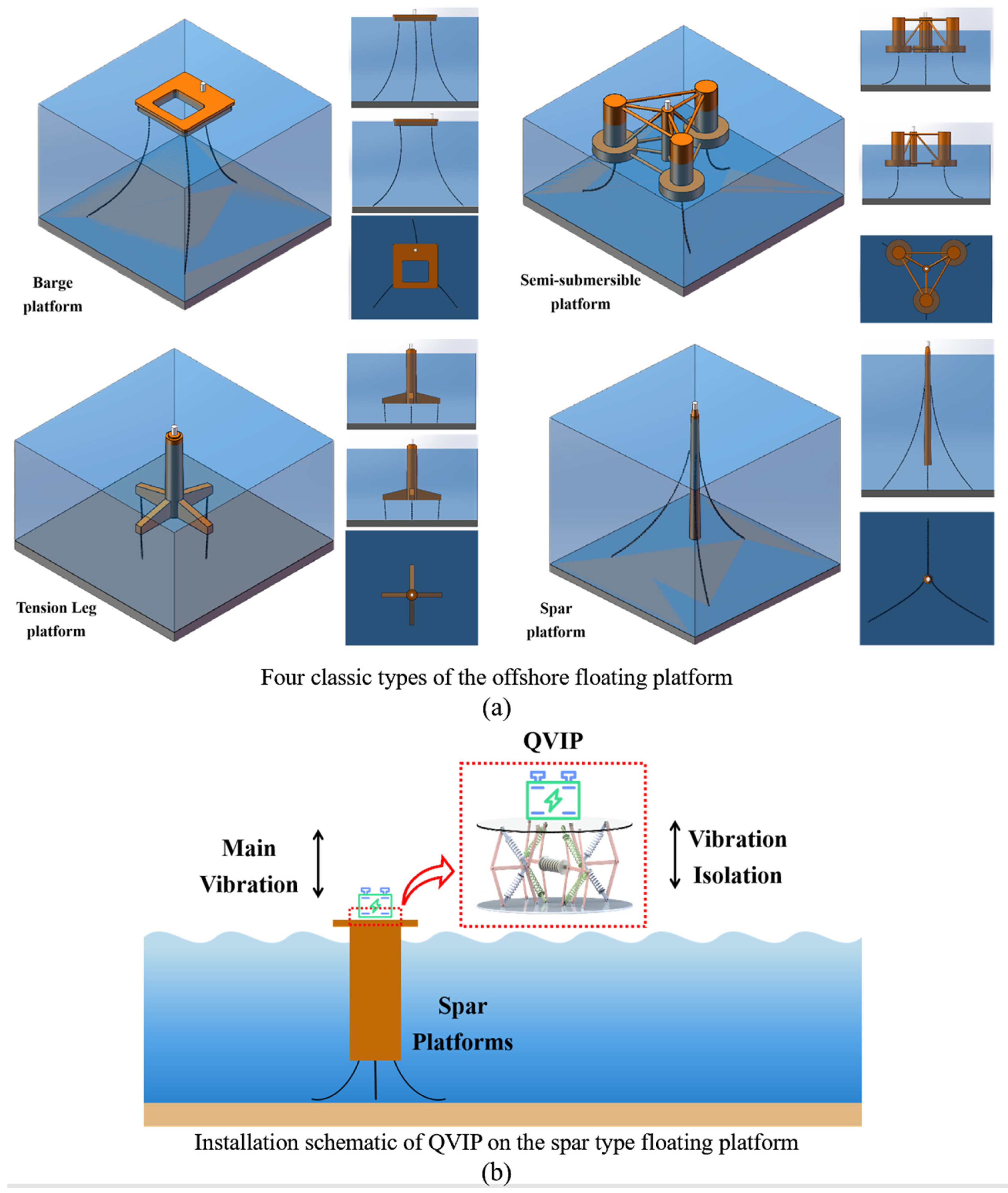
1. Introduction
2. Dynamic Modeling of the Proposed QVIP
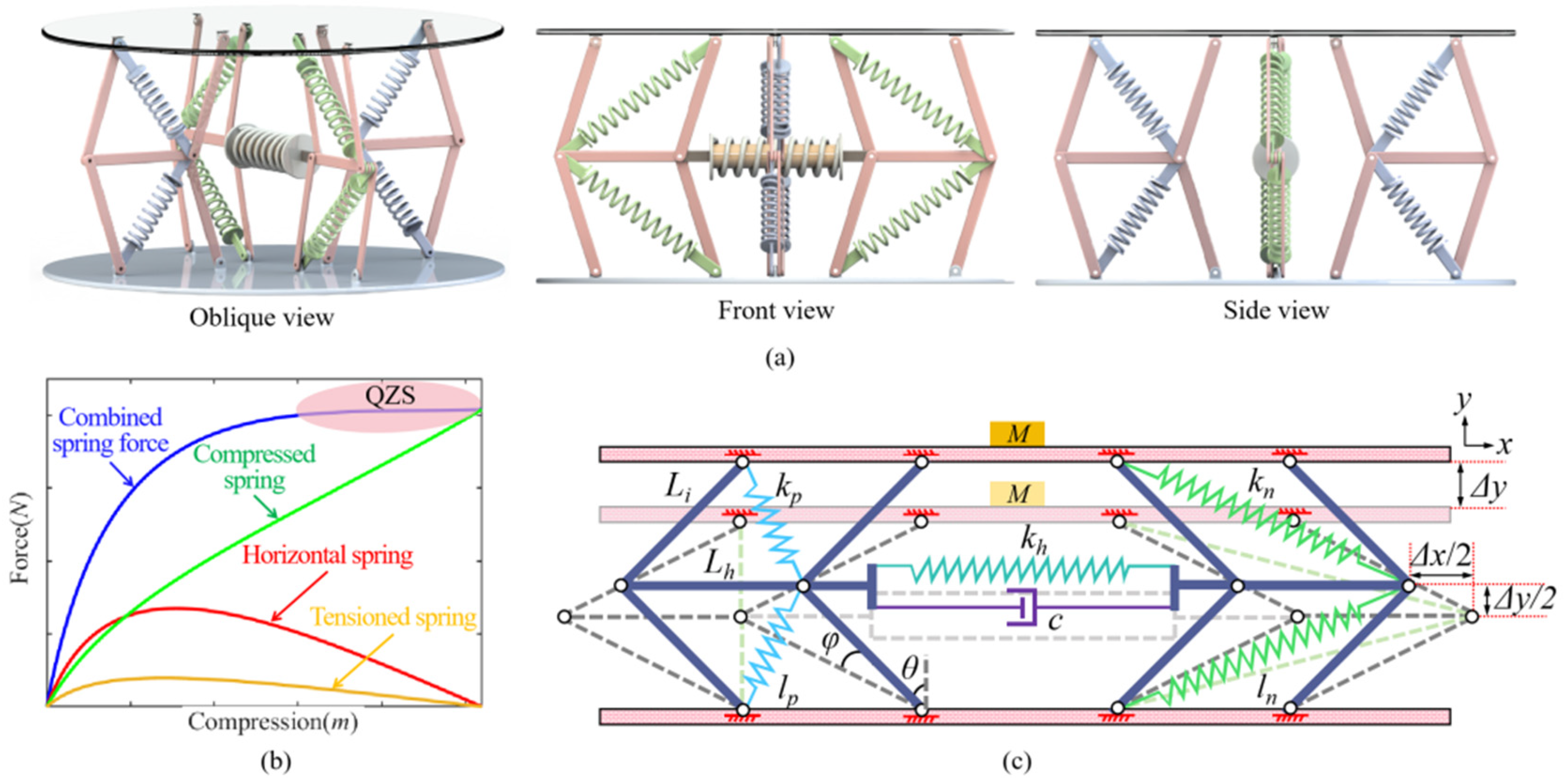
2.1. Conceptual Design of QVIP
2.2. Deformation of the QVIP
2.3. Dynamic Model of the QVIP
3. QZS Characteristics of QVIP
3.1. Static Stiffness
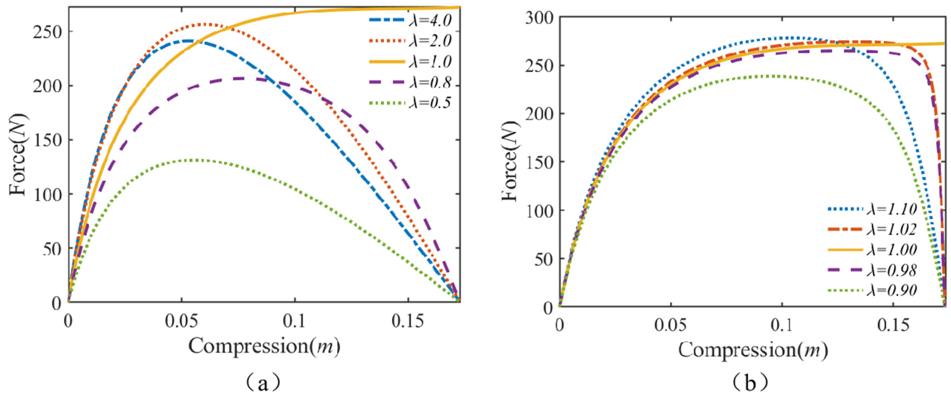
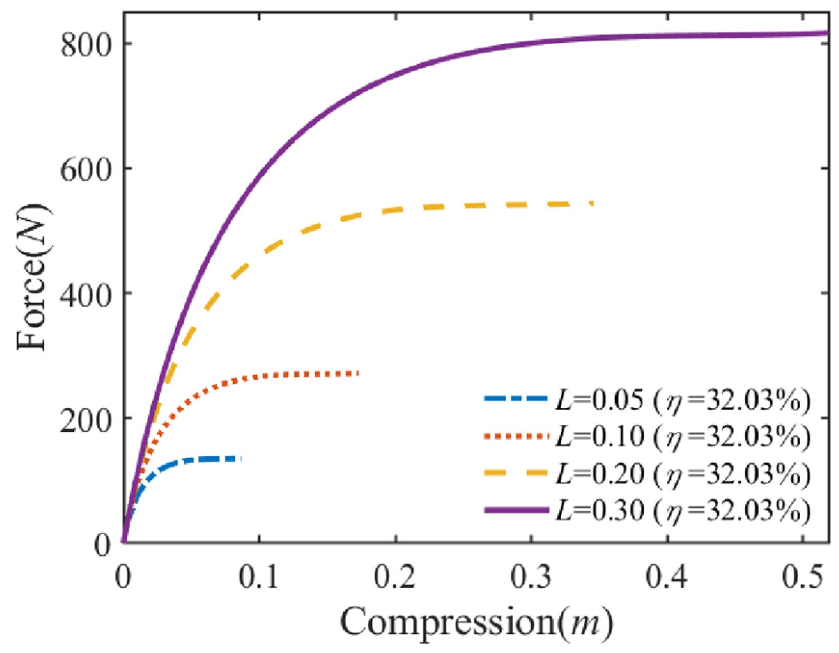
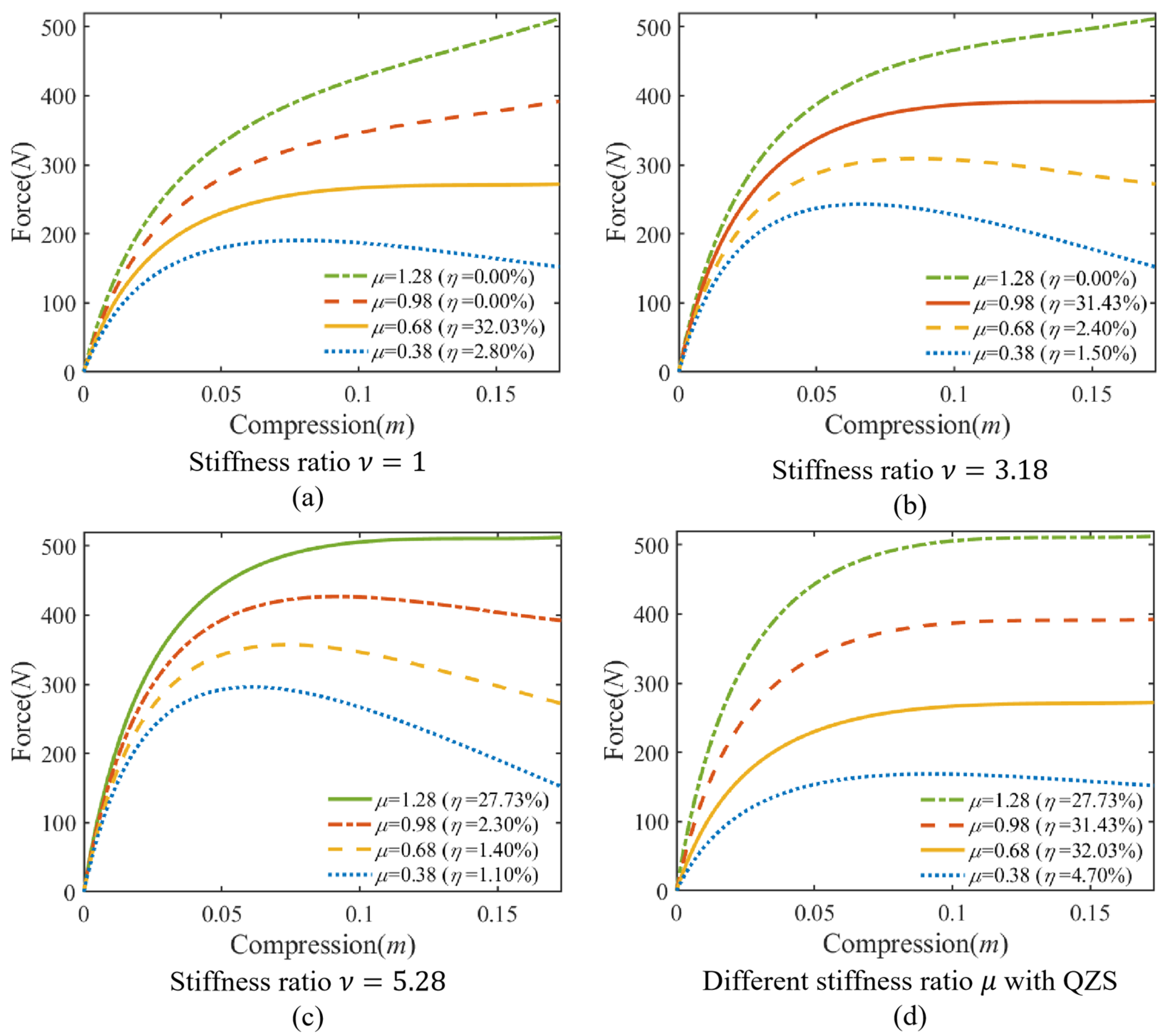
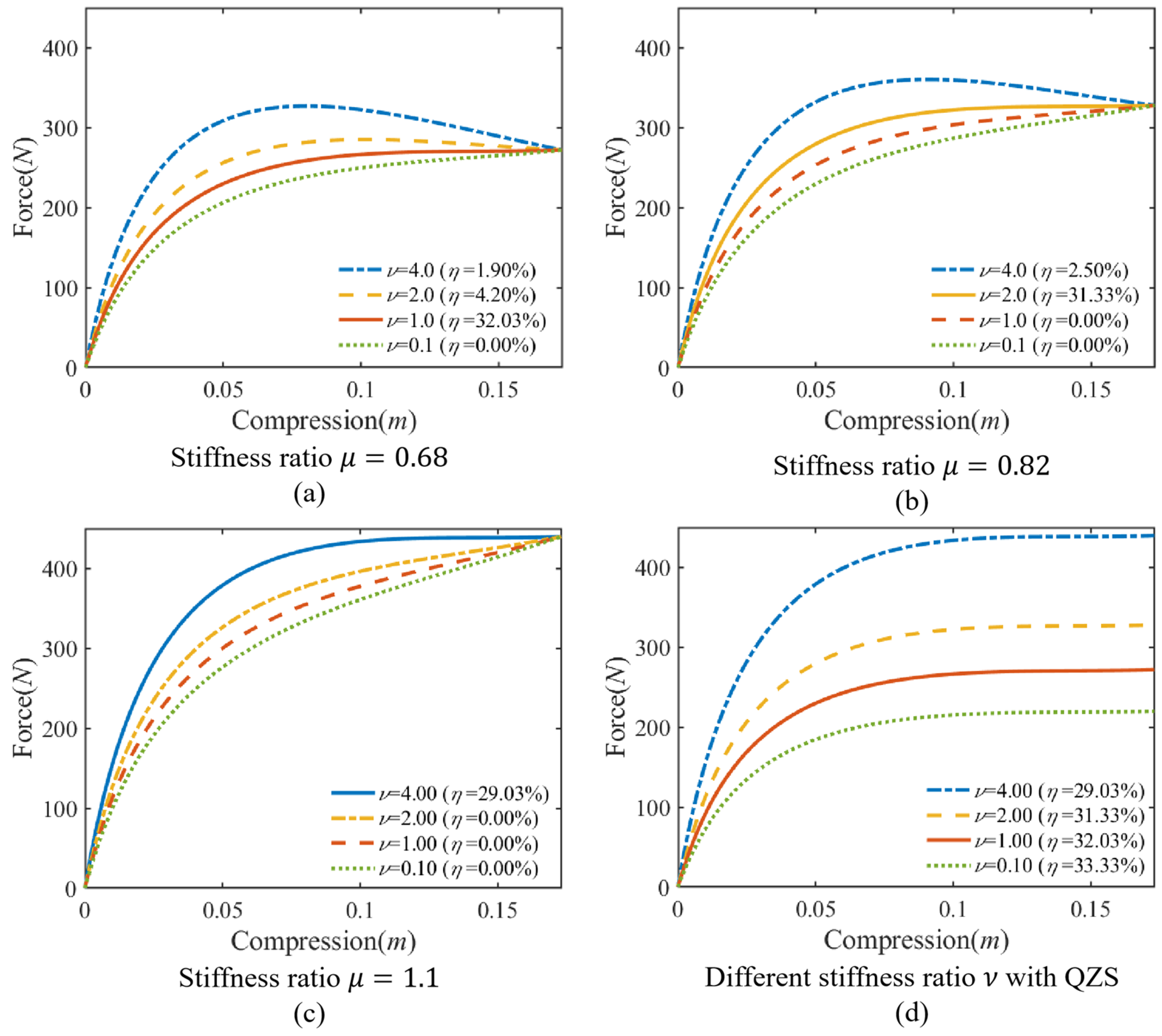
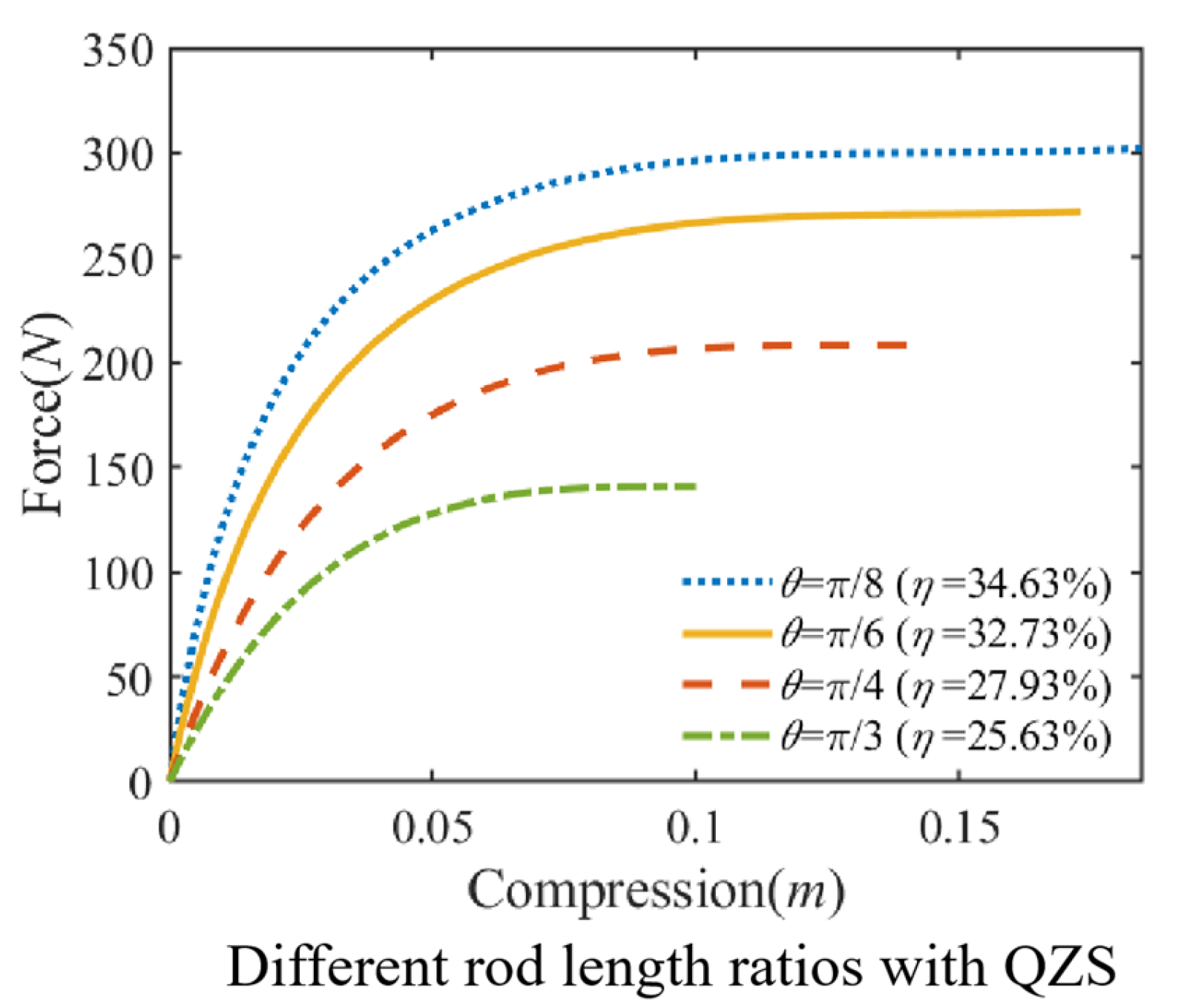
3.2. Parametric Study
4. Simulation Analysis
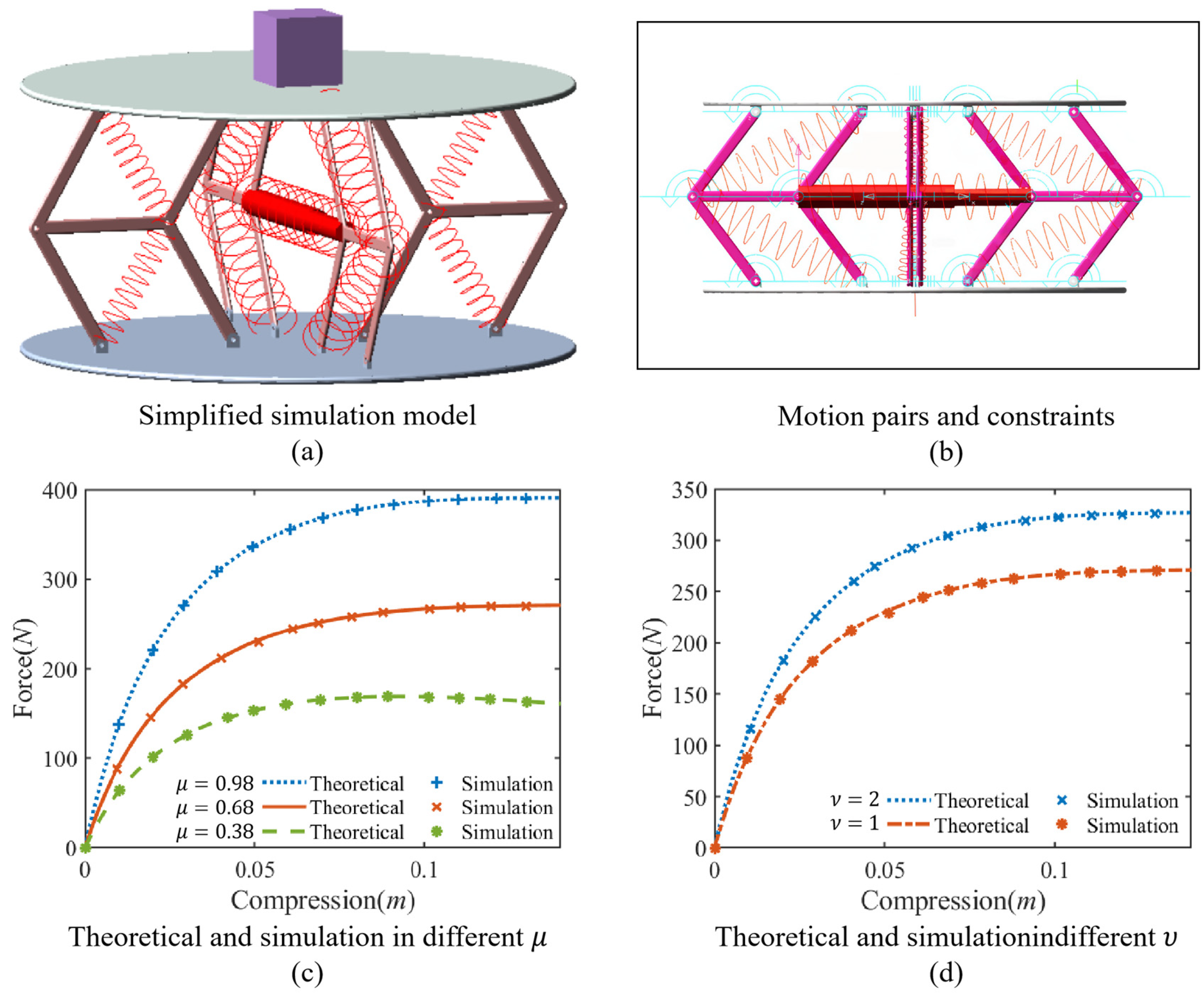
4.1. Simulation Model in Adams
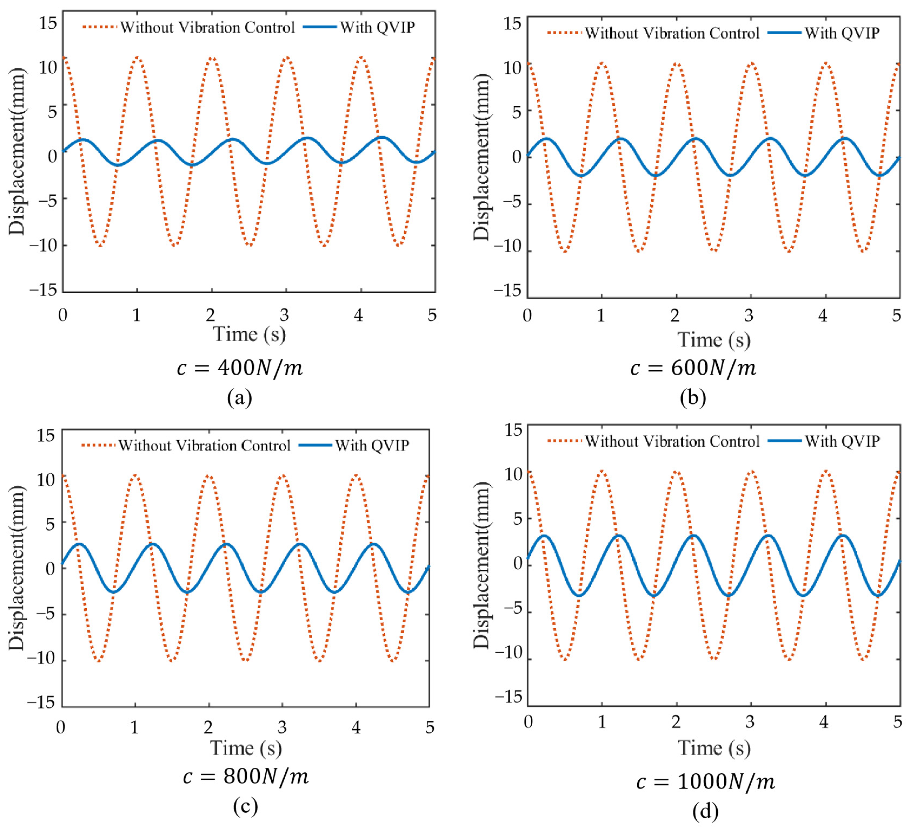
4.2. Case Study
4.3. Vibration Control Effect of Optimally Designed QVIP
5. Conclusions
Author Contributions
Funding
Institutional Review Board Statement
Informed Consent Statement
Data Availability Statement
Conflicts of Interest
Appendix A

| Symbol | Structural Parameters | Unit |
|---|---|---|
| Mass | ||
| Stiffness of horizontal spring | ||
| Stiffness of inclined spring under stretch | ||
| Stiffness of inclined spring under compression | ||
| Stiffness of spring | ||
| Ratio of to | ||
| Ratio of to | ||
| Ratio of to | ||
| Damping coefficient of horizontal damper | ||
| Air damping coefficient | ||
| Length of inclined rod | ||
| Length of horizontal rod | ||
| Length | ||
| Ratio of to | ||
| Ratio of to | ||
| Initial length of compressed inclined spring | ||
| Length of compressed inclined spring during motion | ||
| Deformation of compressed inclined spring | ||
| Initial length of stretch inclined spring | ||
| Length of stretch inclined spring during motion | ||
| Deformation of stretch inclined spring | ||
| Initial angle of inclined rod | ||
| Rotation angle of inclined rod | ||
| Total horizontal displacement | ||
| y | Total vertical displacement |
References
- Huang, Z.; Zhang, Y.; Bian, J. Offshore floating platform synergizing internally-installed self-reacting wave energy converters for optimizing vibration control and energy harvesting. Ocean Eng. 2024, 313, 119429. [Google Scholar] [CrossRef]
- Zhang, B.-L.; Han, Q.-L.; Zhang, X.-M. Recent advances in vibration control of offshore platforms. Nonlinear Dyn. 2017, 89, 755–771. [Google Scholar] [CrossRef]
- Zhang, Y.; Huang, Z.; Bian, J. Multi-dimensional vibration control for offshore floating platform synergizing built-in wave energy converter with decoupled power take-offs. Ocean Eng. 2025, 322, 120450. [Google Scholar] [CrossRef]
- Rahman, M.; Ong, Z.C.; Chong, W.T.; Julai, S.; Khoo, S.Y. Performance enhancement of wind turbine systems with vibration control: A review. Renew. Sustain. Energy Rev. 2015, 51, 43–54. [Google Scholar] [CrossRef]
- Ibrahim, R.A. Recent advances in nonlinear passive vibration isolators. J. Sound Vib. 2008, 314, 371–452. [Google Scholar] [CrossRef]
- Yang, J.; Ning, D.; Sun, S.; Zheng, J.; Lu, H.; Nakano, M.; Zhang, S.; Du, H.; Li, W. A semi-active suspension using a magnetorheological damper with nonlinear negative-stiffness component. Mech. Syst. Signal Process. 2021, 147, 107071. [Google Scholar] [CrossRef]
- Zhang, F.; Shao, S.; Tian, Z.; Xu, M.; Xie, S. Active-passive hybrid vibration isolation with magnetic negative stiffness isolator based on Maxwell normal stress. Mech. Syst. Signal Process. 2019, 123, 244–263. [Google Scholar] [CrossRef]
- Lu, Z.; Wang, Z.; Zhou, Y.; Lu, X. Nonlinear dissipative devices in structural vibration control: A review. J. Sound Vib. 2018, 423, 18–49. [Google Scholar] [CrossRef]
- Bian, J.; Jing, X. Superior nonlinear passive damping characteristics of the bio-inspired limb-like or X-shaped structure. Mech. Syst. Signal Process. 2019, 125, 21–51. [Google Scholar] [CrossRef]
- Liu, C.; Yu, K.; Tang, J. New insights into the damping characteristics of a typical quasi-zero-stiffness vibration isolator. Int. J. Non-Linear Mech. 2020, 124, 103511. [Google Scholar] [CrossRef]
- Hu, X.; Zhou, C. The effect of various damping on the isolation performance of quasi-zero-stiffness system. Mech. Syst. Signal Process. 2022, 171, 108944. [Google Scholar] [CrossRef]
- Donmez, A.; Cigeroglu, E.; Ozgen, G.O. An improved quasi-zero stiffness vibration isolation system utilizing dry friction damping. Nonlinear Dyn. 2020, 101, 107–121. [Google Scholar] [CrossRef]
- Su, N.; Bian, J.; Peng, S.; Chen, Z.; Xia, Y. Analytical optimal design of inerter-based vibration absorbers with negative stiffness balancing static amplification and dynamic reduction effects. Mech. Syst. Signal Process. 2023, 192, 110235. [Google Scholar] [CrossRef]
- Bian, J.; Jing, X. Analysis and design of a novel and compact X-structured vibration isolation mount (X-Mount) with wider quasi-zero-stiffness range. Nonlinear Dyn. 2020, 101, 2195–2222. [Google Scholar] [CrossRef]
- Chai, Y.; Bian, J.; Li, M. A novel quasi-zero-stiffness isolation platform via tunable positive and negative stiffness compensation mechanism. Nonlinear Dyn. 2023, 112, 101–123. [Google Scholar] [CrossRef]
- Liu, C.; Zhang, W.; Yu, K.; Liu, T.; Zheng, Y. Quasi-zero-stiffness vibration isolation: Designs; improvements and applications. Eng. Struct. 2024, 301, 117282. [Google Scholar] [CrossRef]
- Liu, C.; Yu, K. Accurate modeling and analysis of a typical nonlinear vibration isolator with quasi-zero stiffness. Nonlinear Dyn. 2020, 100, 2141–2165. [Google Scholar] [CrossRef]
- Zhao, F.; Ji, J.C.; Ye, K.; Luo, Q. Increase of quasi-zero stiffness region using two pairs of oblique springs. Mech. Syst. Signal Process. 2020, 144, 106975. [Google Scholar] [CrossRef]
- Zhao, F.; Ji, J.; Ye, K.; Luo, Q. An innovative quasi-zero stiffness isolator with three pairs of oblique springs. Int. J. Mech. Sci. 2021, 192, 106093. [Google Scholar] [CrossRef]
- Tian, Y.; Cao, D.; Wang, Y.; Tang, J.; Jiang, B. A Study of a Pendulum-Like Vibration Isolator With Quasi-Zero-Stiffness. J. Comput. Nonlinear Dyn. 2022, 17, 051005. [Google Scholar] [CrossRef]
- Liu, C.; Zhao, R.; Yu, K.; Lee, H.P.; Liao, B. A quasi-zero-stiffness device capable of vibration isolation and energy harvesting using piezoelectric buckled beams. Energy 2021, 233, 121146. [Google Scholar] [CrossRef]
- Yan, B.; Yu, N.; Wang, Z.; Wu, C.; Wang, S.; Zhang, W. Lever-type quasi-zero stiffness vibration isolator with magnetic spring. J. Sound Vib. 2022, 527, 116865. [Google Scholar] [CrossRef]
- Xu, D.; Yu, Q.; Zhou, J.; Bishop, S.R. Theoretical and experimental analyses of a nonlinear magnetic vibration isolator with quasi-zero-stiffness characteristic. J. Sound Vib. 2013, 332, 3377–3389. [Google Scholar] [CrossRef]
- Feng, X.; Jing, X. Human body inspired vibration isolation: Beneficial nonlinear stiffness, nonlinear damping & nonlinear inertia. Mech. Syst. Signal Process. 2019, 117, 786–812. [Google Scholar]
- Deng, T.; Wen, G.; Ding, H.; Lu, Z.-Q.; Chen, L.-Q. A bio-inspired isolator based on characteristics of quasi-zero stiffness and bird multi-layer neck. Mech. Syst. Signal Process. 2020, 145, 106967. [Google Scholar] [CrossRef]
- Ling, P.; Miao, L.; Zhang, W.; Wu, C.; Yan, B. Cockroach-inspired structure for low-frequency vibration isolation. Mech. Syst. Signal Process. 2022, 171, 108955. [Google Scholar] [CrossRef]
- Li, M.; Zhou, J.; Jing, X. Improving low-frequency piezoelectric energy harvesting performance with novel X-structured harvesters. Nonlinear Dyn. 2018, 94, 1409–1428. [Google Scholar] [CrossRef]
- Yan, G.; Zou, H.-X.; Wang, S.; Zhao, L.-C.; Wu, Z.-Y.; Zhang, W.-M. Bio-inspired toe-like structure for low-frequency vibration isolation. Mech. Syst. Signal Process. 2022, 162, 108010. [Google Scholar] [CrossRef]
- Bian, J.; Zhou, X.H.; Ke, K.; Yam, M.C.H.; Wang, Y.H.; Qiu, Y. A passive vibration isolator with bio-inspired structure and inerter nonlinear effects. Struct. Eng. Mech. 2023, 88, 221–238. [Google Scholar]
- Yu, Y.; Yao, G.; Wu, Z. Nonlinear primary responses of a bilateral supported X-shape vibration reduction structure. Mech. Syst. Signal Process. 2020, 140, 106679. [Google Scholar] [CrossRef]
- Chai, Y.; Jing, X.; Chao, X. X-shaped mechanism based enhanced tunable QZS property for passive vibration isolation. Int. J. Mech. Sci. 2022, 218, 107077. [Google Scholar] [CrossRef]
- Li, M.; Cheng, W.; Xie, R. A quasi-zero-stiffness vibration isolator using a cam mechanism with user-defined profile. Int. J. Mech. Sci. 2021, 189, 105938. [Google Scholar] [CrossRef]
- Zhang, Y.; Wei, G.; Wen, H.; Jin, D.; Hu, H. Design and analysis of a vibration isolation system with cam–roller–spring–rod mechanism. J. Vib. Control 2021, 28, 1781–1791. [Google Scholar] [CrossRef]
- Cai, C.; Zhou, J.; Wu, L.; Wang, K.; Xu, D.; Ouyang, H. Design and numerical validation of quasi-zero-stiffness metamaterials for very low-frequency band gaps. Compos. Struct. 2020, 236, 111862. [Google Scholar] [CrossRef]
- Yan, B.; Ma, H.; Yu, N.; Zhang, L.; Wu, C. Theoretical modeling and experimental analysis of nonlinear electromagnetic shunt damping. J. Sound Vib. 2020, 471, 115184. [Google Scholar] [CrossRef]
- Liu, C.; Yu, K.; Liao, B.; Hu, R. Enhanced vibration isolation performance of quasi-zero-stiffness isolator by introducing tunable nonlinear inerter. Commun. Nonlinear Sci. Numer. Simul. 2021, 95, 105654. [Google Scholar] [CrossRef]
- Lv, Q.; Yao, Z. Analysis of the effects of nonlinear viscous damping on vibration isolator. Nonlinear Dyn. 2014, 79, 2325–2332. [Google Scholar] [CrossRef]
- Dong, G.; Zhang, Y.; Luo, Y.; Xie, S.; Zhang, X. Enhanced isolation performance of a high-static–low-dynamic stiffness isolator with geometric nonlinear damping. Nonlinear Dyn. 2018, 93, 2339–2356. [Google Scholar] [CrossRef]
- Zhang, J.; He, H.; Zhang, Z. Research Status and Development Prospects of Offshore Wind Turbine Foundation Structures. Nav. Archit. Ocean Eng. 2023, 39, 1–6. [Google Scholar]

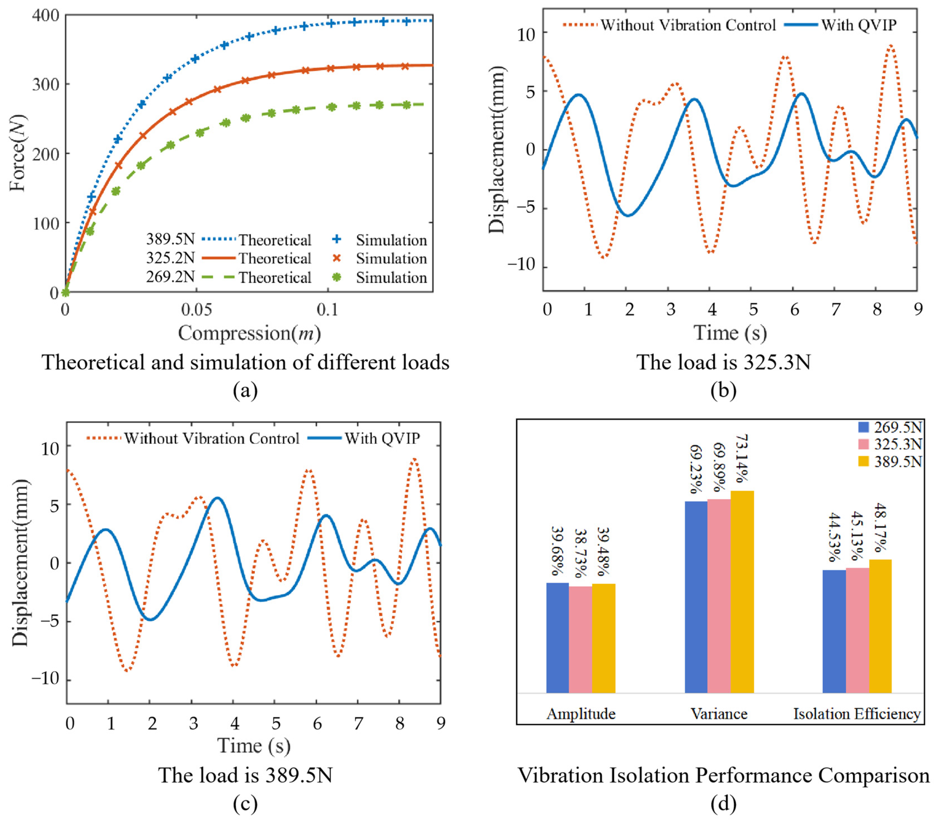
| Platform Load (N) | Metric | Without Isolation | With QVIP | Reduction Percentage |
|---|---|---|---|---|
| 269.5 | Maximum Amplitude (m) | 0.00917 | 0.00553 | 39.68% |
| Variance | 25.48 | 7.84 | 69.23% | |
| Vibration Isolation Efficiency | 44.53% | |||
| 325.3 | Maximum Amplitude (m) | 0.00914 | 0.0056 | 38.73% |
| Variance | 25.87 | 7.79 | 69.89% | |
| Vibration Isolation Efficiency | 45.13% | |||
| 389.5 | Maximum Amplitude (m) | 0.00915 | 0.00554 | 39.48% |
| Variance | 25.47 | 6.84 | 73.14% | |
| Vibration Isolation Efficiency | 48.17% | |||
Disclaimer/Publisher’s Note: The statements, opinions and data contained in all publications are solely those of the individual author(s) and contributor(s) and not of MDPI and/or the editor(s). MDPI and/or the editor(s) disclaim responsibility for any injury to people or property resulting from any ideas, methods, instructions or products referred to in the content. |
© 2025 by the authors. Licensee MDPI, Basel, Switzerland. This article is an open access article distributed under the terms and conditions of the Creative Commons Attribution (CC BY) license (https://creativecommons.org/licenses/by/4.0/).
Share and Cite
Guo, Z.; Bian, J.; Li, L.; Su, N. A Novel Quadrilateral-Shaped Vibration Isolation Platform and Its Application in the Offshore Floating Platform. Appl. Sci. 2025, 15, 7456. https://doi.org/10.3390/app15137456
Guo Z, Bian J, Li L, Su N. A Novel Quadrilateral-Shaped Vibration Isolation Platform and Its Application in the Offshore Floating Platform. Applied Sciences. 2025; 15(13):7456. https://doi.org/10.3390/app15137456
Chicago/Turabian StyleGuo, Zhenbin, Jing Bian, Liangyu Li, and Ning Su. 2025. "A Novel Quadrilateral-Shaped Vibration Isolation Platform and Its Application in the Offshore Floating Platform" Applied Sciences 15, no. 13: 7456. https://doi.org/10.3390/app15137456
APA StyleGuo, Z., Bian, J., Li, L., & Su, N. (2025). A Novel Quadrilateral-Shaped Vibration Isolation Platform and Its Application in the Offshore Floating Platform. Applied Sciences, 15(13), 7456. https://doi.org/10.3390/app15137456