Article

A Study on the Vertical Bearing Characteristics of Screw Piles in Permafrost Regions

by
Tao Liu
1,
Jun Lv
1,
Xuyan Deng
2,
Chunxiang Guo
3,*,
Weijia Zhang
3 and
Daijun Jiang
3
1
Power China Guiyang Engineering Corporation Limited, Guiyang 550081, China
2
Power China Engineering Corporation of Southwest Headquarters, Chengdu 610036, China
3
School of Civil Engineering, Lanzhou Jiaotong University, Lanzhou 730070, China
*
Author to whom correspondence should be addressed.
Appl. Sci. 2025, 15(13), 7416; https://doi.org/10.3390/app15137416
Submission received: 31 March 2025 / Revised: 5 June 2025 / Accepted: 22 June 2025 / Published: 1 July 2025

Abstract

The screw piles used in permafrost regions represent a new type of pile, and their vertical bearing characteristics play a crucial role in ensuring the normal operation of engineering buildings. This study establishes a numerical calculation model to simulate the interaction between screw piles and soil in permafrost regions and verifies the numerical simulation results through model tests. The bearing mechanism of screw piles in permafrost areas is studied and compared with common, bored, cast-in-place piles widely used. Finally, a method for estimating the bearing capacity of screw piles in permafrost regions is proposed. The research indicates that approximately 90% of the bearing capacity of screw piles in permafrost regions is derived from the mechanical interaction between the concrete pile’s side and the permafrost soil. The shear strength of the permafrost is the primary determinant of the pile foundation’s bearing capacity, while the seasonally active layer has a minimal impact on its bearing capacity, resulting in a stable year-round performance. In permafrost regions, the equivalent friction resistance of screw piles is significantly greater than that of the conventional cast-in-place piles. When the pile reaches its ultimate bearing capacity, the plastic zone on the pile’s side becomes connected, and shear failure occurs in the surrounding soil. The design value of the bearing capacity of a single pile can be effectively estimated in engineering practice by improving the formula of the code for calculating the vertical bearing capacity.

1. Introduction

China’s permafrost area accounts for approximately 22% of the country’s total land area, with most of it located on the Tibetan Plateau [1,2]. With the ongoing development of Western China, the engineering projects being constructed and operated in permafrost areas include the Qinghai–Tibet Railway, Qinghai–Tibet Highway, and Qinghai–Tibet Power Transmission Line [2]. Pile foundations are one of the most commonly used forms when designing foundations for these engineering projects [3,4,5]. Under the general trend of global warming, an abnormal climate, and the degradation of frozen soil, engineering construction in permafrost regions faces increasing demands related to the foundation-bearing capacity. The drilled screw pile is a new type of pile used in permafrost regions. It interacts with the seasonally active soil layer through a steel sleeve, effectively reducing frost heave damage. Additionally, the outer thread and the frozen soil’s mechanical bite provide a good vertical bearing capacity in permafrost.
Screw piles are widely used in areas with soft soil, and numerous scholars have investigated their bearing capacity and pulling resistance characteristics. Li Hongwen et al. [6] provided a preliminary discussion on the bearing capacity design of the screw pile and provided guidance for construction. Malik, AA et al. [7] investigated the end-bearing capacity of screw and straight-pipe piles under similar pile-tip areas and ground conditions. Through laboratory testing and numerical analyses, Li Chengwei et al. [8] studied the vertical bearing capacity mechanism of bored, cast-in-place screw piles and proposed that the soil’s shear strength index and the screw pitch and the screw width of screw piles are the key factors affecting the vertical bearing capacity of screw piles. Qian Jiangu et al. [9] measured the relationship between the shear stress and the relative shear displacement of the common pile–soil contact surface with different screw pitches by using a large-scale contact surface shear test and found that there is an optimal screw pitch that causes the maximum arch failure surface of the screw pile and the soil. Zhou Yang et al. [10] conducted laboratory tests on screw piles with variable sections and found that the material utilization rate of screw piles with variable sections was approximately 1.3 times that of screw piles with constant sections under the same formation conditions. These studies provide a valuable reference for the engineering practice with regard to screw piles in areas with soft soil. However, the soil in permafrost regions undergoes a water–ice phase transition after freezing [11,12,13], and the temperature, water content, and ice content of the frozen soil affect the bearing performance of piles [14,15,16]. Currently, there are few studies on drilled screw piles in permafrost areas. Therefore, researching screw piles in permafrost areas is of great value, as their potential application is of significant importance [17,18,19].
In this study, the accuracy of the numerical method is verified by laboratory model tests. Subsequently, the vertical load transfer characteristics and bearing mechanisms of the drilled screw piles in the permafrost regions of the typically humid area of the Qinghai–Tibet Plateau are investigated using numerical methods, and the bearing capacity calculation method is proposed.

2. Model Test

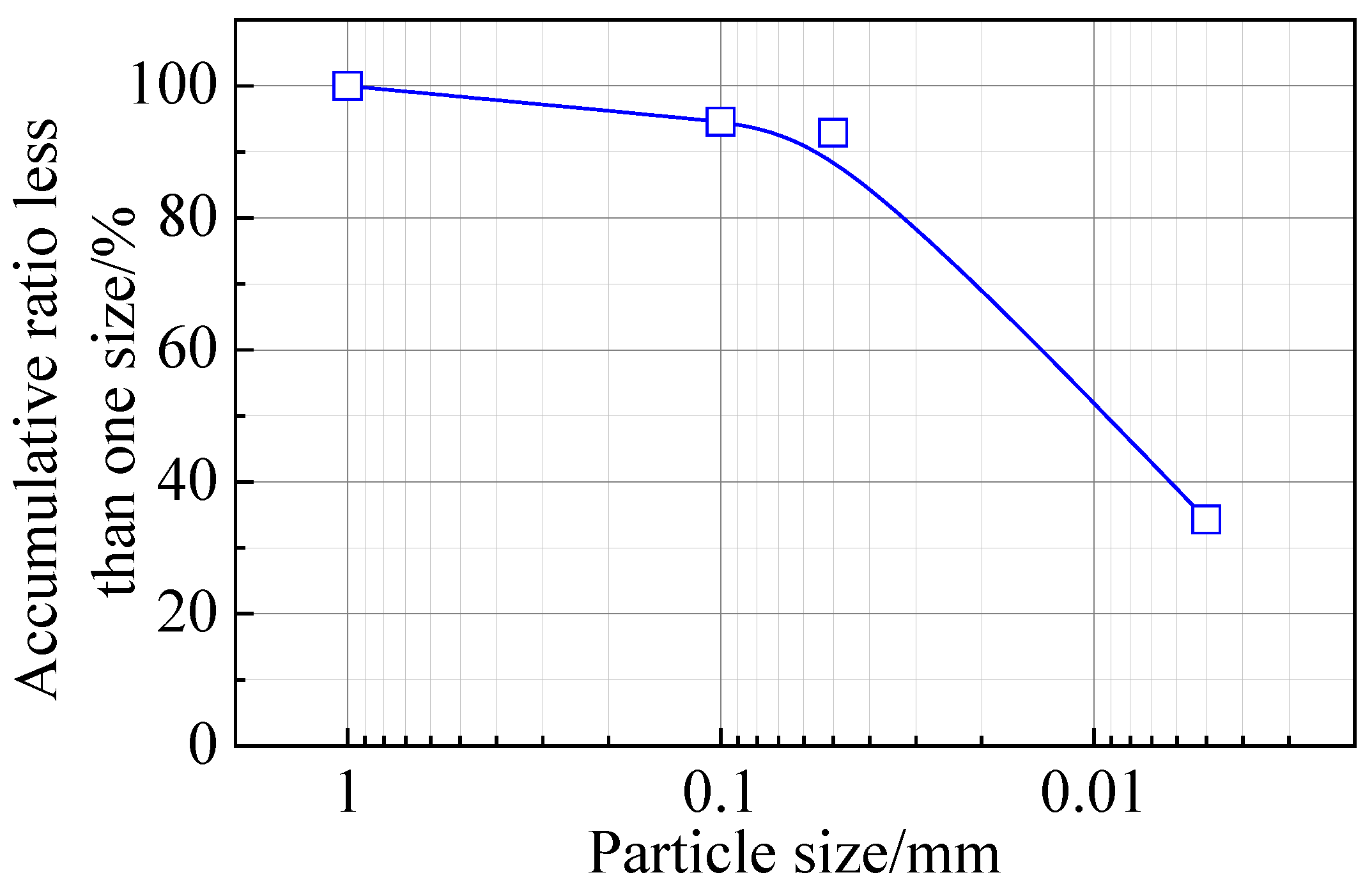
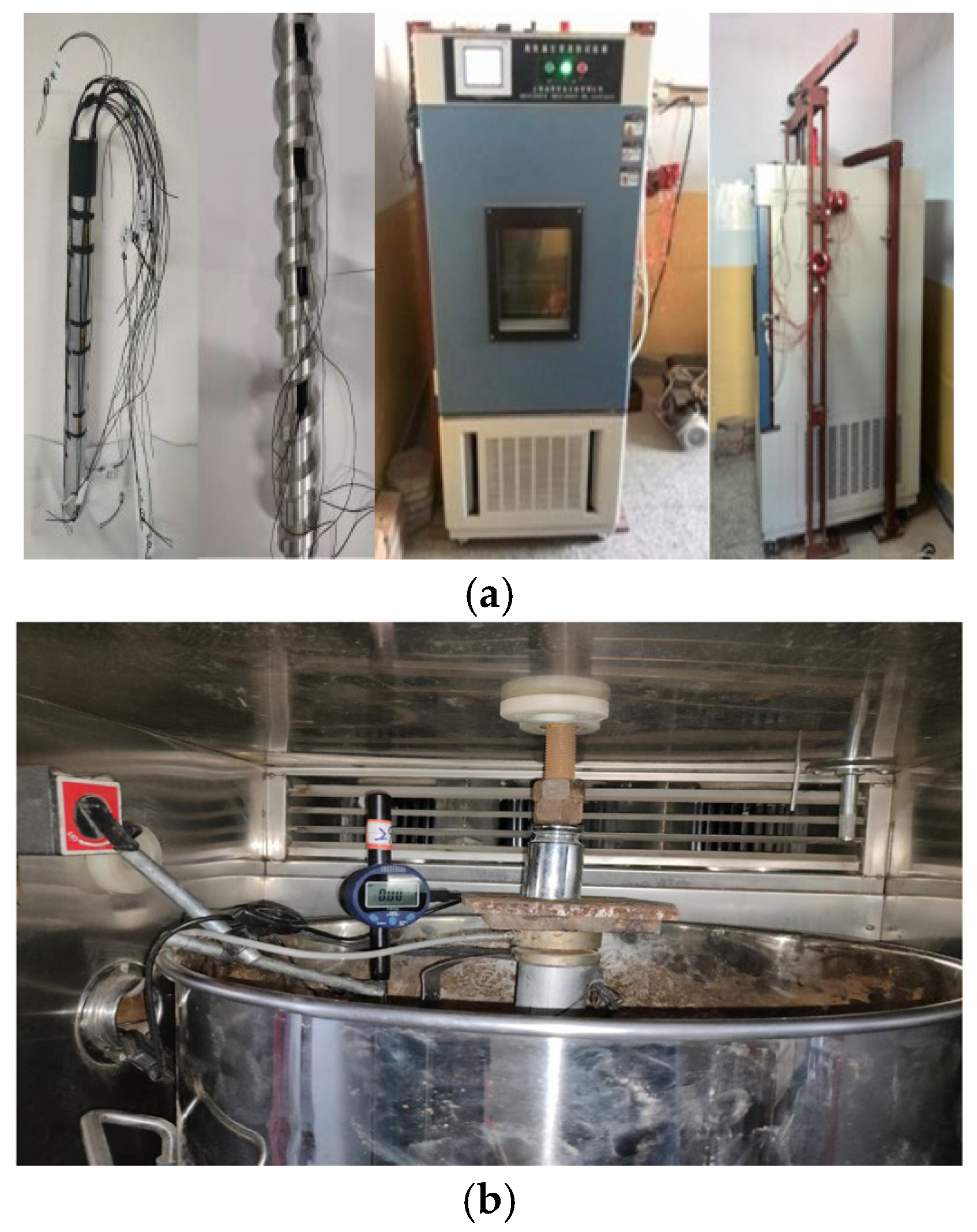
2.1. Design of Experiment

The body of the test pile is made of aluminum alloy. The length of the conventional, ordinary pile is 40 cm, and it has a diameter of 4.5 cm. The screw pile has a length of 40 cm, an inner diameter of 4.5 cm, an outer diameter of 6 cm, a pitch of 4 cm, and a thread width of 1.2 cm. Strain gauges were arranged symmetrically on both sides of the pile’s body, with seven groups placed for a single pile. The pile’s body was placed in the test chamber for loading. The diameter of the test chamber was 45 cm, and the depth was 65 cm. The soil width range around the pile was 45 cm, and the soil depth was 2 times the pile length, making it 80 cm, which can simulate the bearing capacity characteristics of the pile’s body in the semi-infinite stratum, as indicated in Figure 1. Temperature sensors were installed every 10 cm in a downward direction along the depth of the soil in the model test chamber, with a total of 8 temperature sensors, to test the soil temperature. Standard loess from Lanzhou, China, was selected for this test, with a density of 1650 kg·m−3. The liquid limit was 24.6%, and the plastic limit was 17.7%. Figure 2 depicts the particle size distribution curve of standard loess. The collected standard loess soil sample was mixed with water, and the water content was set at 21%. A heavy hammer was used to compact every 5 cm of soil, and each layer’s compaction work was controlled at approximately 50.6 kJ∙m−3. Once the pile–soil model was created, it was placed in a low-temperature environmental test chamber and frozen for 3–4 days until the temperature reached the test value of −0.5 °C. This temperature condition corresponds to high-temperature frozen soil [14].
The low-temperature control system utilizes a GDJS-150 high- and low-temperature alternating wet heat test box. This test box can simulate a temperature range of −40~−150 °C, with a temperature control error of ±0.1 °C, which enables the simulation of a permafrost environment. The lever loading method is employed in the test, and the loading rod features three holes. By changing the hole positions, the system can be amplified and loaded to the top of the pile. Before loading, the pressure sensor is placed on top of the pile. The first level of the load is the weight of the loading device, and the second level is the weight of the weight box. The weight of the loading device is displayed through the pressure sensor reading. The lever loading system and the low-temperature control system are illustrated in Figure 3. Displacement data are collected by directly connecting the digital dial indicator to the computer. The test adopts the fast-loading method. The load is maintained for 2 h, and the settlement of the pile’s top converges; the next stage is then applied. If the settlement amount is twice the previous stage’s load, it is considered to be damaged [17].

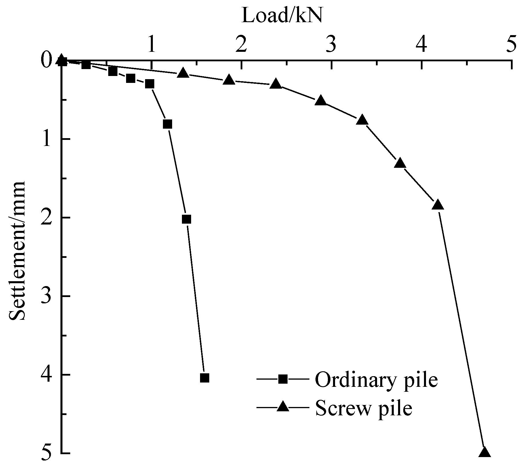
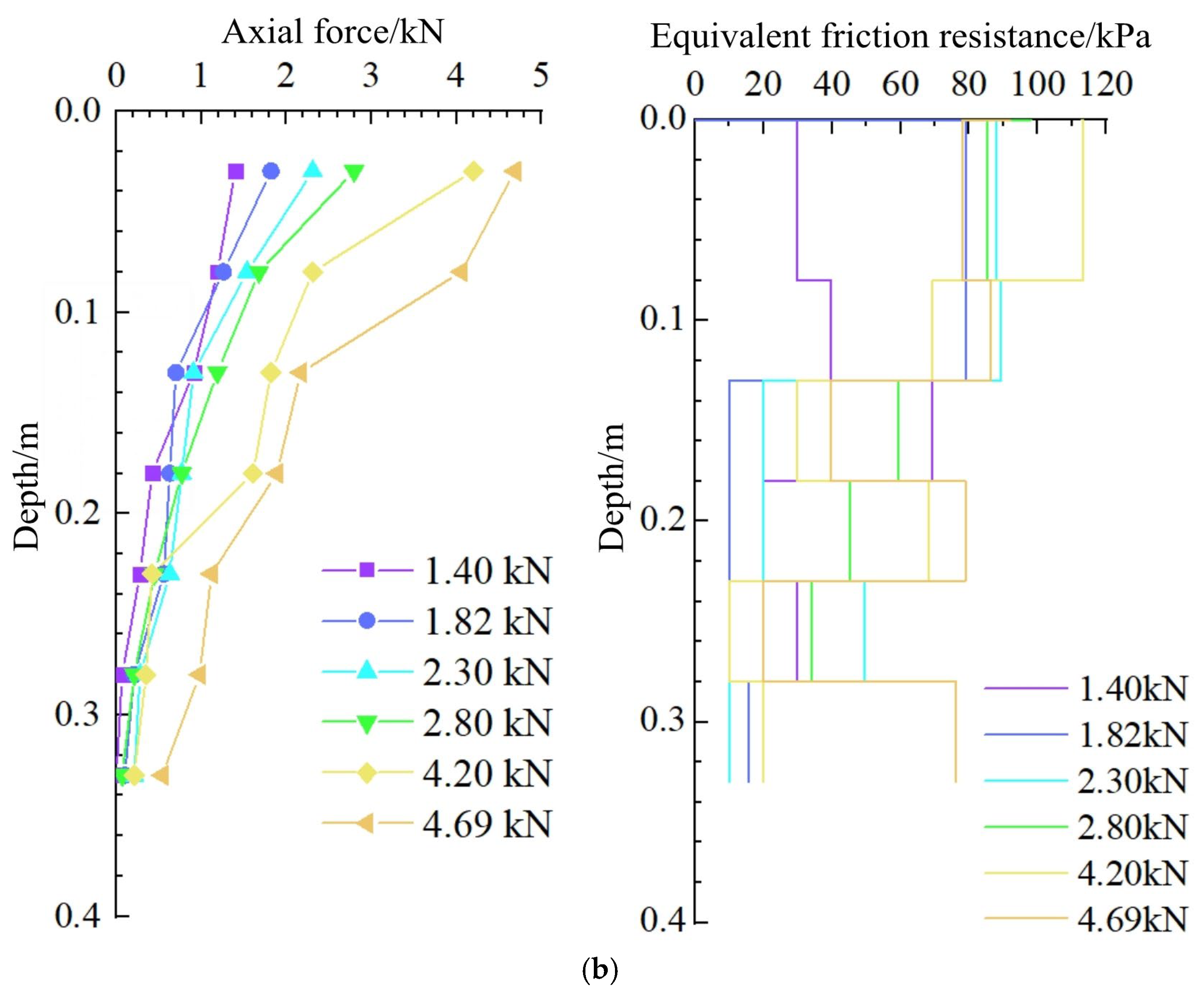
2.2. Test Results and Analysis

The load-settlement curves obtained from the two types of piles under model tests are indicated in Figure 4. As depicted in the figure, the load-settlement curve of the ordinary pile indicates a typical failure mode of the friction pile, with a settlement of 4.12 mm under the load of 1.58 kN. For the screw pile, the initial load stage is 1.4 kN, while the failure load reaches 4.69 kN, with a corresponding settlement of 4.99 mm. The ultimate bearing load of the screw pile is 2.97 times greater than that of the ordinary pile.
The lateral friction resistance of screw piles is simplified and calculated based on the equivalent lateral friction resistance of the pile’s body, and the calculation formula is as follows [10,20]:
τ i = Q i + 1 Q i π D h i
where τi represents the equivalent friction resistance of the pile’s side (kPa). Qi+1 and Qi are the axial forces at both ends of the pile’s body’s stress section, respectively (kN). D denotes the diameter of the pile’s body, and the screw pile takes the outer diameter (m). hi represents the length of the bearing section of the pile’s body.
Figure 5 indicates the axial force and the equivalent frictional resistance of the model piles. It can be observed from the figure that the axial force on the ordinary pile’s body gradually decreases along the depth, and the lateral friction resistance of the pile begins from the top of the pile, with the increase of the load, and then gradually reaches the maximum shear strength of 35 kPa. The axial force on the screw pile changes sharply, and the equivalent friction resistance of the pile’s side indicates non-uniformity, and the friction resistance of the pile’s top develops first with the increase of the load. Generally, the equivalent friction resistance on the side of a screw pile is significantly greater than that of the ordinary pile.

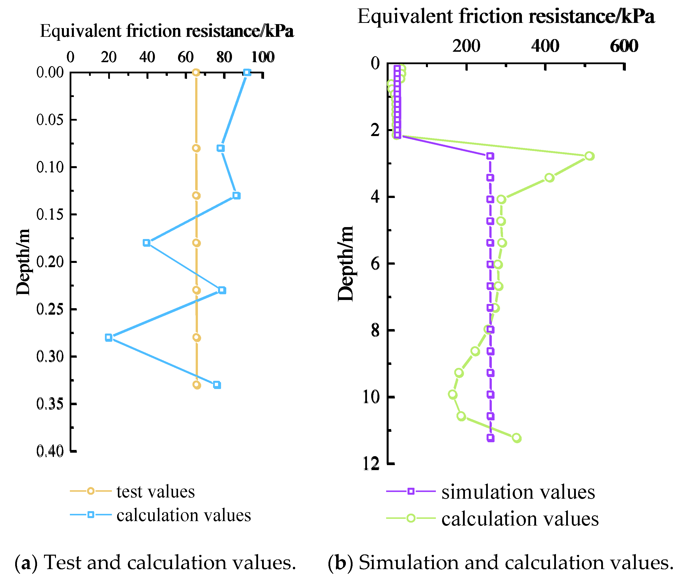
2.3. Comparison Between Numerical Simulation and Laboratory Test

The finite element model was established according to the model parameters used in the laboratory test, as depicted in Figure 5a. The frozen soil was frozen at −0.5 °C. The elastoplastic model of the Mohr–Coulomb yield criterion was used for the soil, while the linear elastic model was used for the pile. The 10-node quadratic tetrahedral mesh element of C3D10 was used as the soil mesh unit around the pile. To reduce the calculation time, the mesh size near the pile was small, and far away, it was large. The mesh element of the pile’s body also adopted the 10-node quadratic tetrahedral mesh element of C3D10. In the model, the lateral constraints of the soil were in the x and y directions, and the z direction was free. The bottom of the soil was fixed and constrained in the x, y, and z directions. The loading of the pile was achieved by applying a vertical displacement of 4 mm at the top of the pile.
Figure 6b indicates the typical shear stress–shear displacement curves from the shear test on the contact surface of the frozen concrete [11,12]. The bond and the Coulomb friction models were combined to simulate the shear characteristics of the contact surface of frozen concrete. The ice-bonding force on the contact surface of the frozen concrete was simulated using the bonding model, in which the damage evolution was simulated to simulate the shear stress attenuation after the contact surface of the frozen concrete reached the maximum shear stress. The decay-and-stability stage of the contact surface of the frozen concrete was simulated by the Coulomb friction model. The material parameters reflect those in the relevant literature [11,12], and the specific values are provided in Table 1.
The comparison between the model test results and the simulation results is depicted in Figure 6c. The settlement of the ordinary pile is small before failure, and its ultimate failure load is consistent with the test results. The initial stage of the screw pile’s load-settlement curve fits well with the test results, and its failure load is also close to that seen in the test results. Generally, the numerical analysis results are in good agreement with the experimental results, verifying the reliability of the numerical method.

3. Numerical Simulation Analysis

The permafrost regions in the typical wet section of the Qinghai–Tibet Plateau were selected as the study site [14]. The pile’s length is 14 m, the diameter of the pile’s body is 0.8 m, the diameter of the pile’s side is 1.1 m, and the thread spacing is 0.65 m. The upper section, in the 2.6 m deep seasonal activity layer, has no thread, and the surface is in contact with the frozen soil via the steel sleeve.

3.1. Calculation Model and Model Parameters

The soil around the pile is 10 times the pile’s diameter, meaning it spreads 12 m in the horizontal direction, and the soil depth is 1.5 times the pile’s length, meaning it continues 18 m in the vertical direction, which is indicated in Figure 7a. The soil layer consists of silty clay (0~6 m) and sub-clay containing peat (6~12 m). The water content of both of the two kinds of soil is approximately 40%. Previous studies [8,9] reveal that the mechanical properties of the two types of soil are closely related to temperature: their cohesion is greatly affected by temperature change, and the internal friction angle of the soil is close to 0 °C under negative temperature conditions. The change in the soil cohesion with temperature is depicted in Figure 7b [11,12]. The temperature field was assigned to the model by way of a pre-defined field, and the temperature field is indicated in Figure 7c. The pile’s body is subjected to frost heave during loading in February in winter, which was simulated by applying prestress onto the surface of the active layer on the side of the pile. The Coulomb friction model was used on the contact surface of the melting active layer, and the friction coefficient was 0.28. The bond model was used to simulate the characteristics of the frozen soil’s contact surface by defining the maximum damage strength and the influence curves of temperature on the shear characteristics of the contact surface, as depicted in Figure 8 [9].

3.2. Analysis of Calculation Results

Figure 9a indicates the load-settlement curves of the screw pile loaded underground during typical temperatures for February and August. It can be observed that the ultimate bearing capacity of the pile’s foundation is less affected by the ground temperature, and the difference between the ultimate bearing capacity of the pile’s foundation in February and August is 412 kN. The bearing capacity of the pile’s foundation is primarily provided by the pile’s side, and the end bearing force accounts for less than 10.1%.
The axial force on the screw pile during loading is depicted in Figure 9b,c. When loading in summer, the axial force on the pile’s body changes little in the upper, non-screw section and increases after entering the screw section. The load on the pile’s body is primarily borne by the screw section in the permafrost. The seasonally active layer melts in summer and contacts with the steel casing, which is the main reason for the small change in the axial force in this section. When loading in winter and summer, the axial force on the pile’s body changes little in the upper, non-screw section and increases after entering the screw section. The load is primarily borne by the thread section in the permafrost. The seasonally active layer produces a frost-jacking force when the soil layer is frost-heaving in winter, and the axial force on the pile’s body is different from that in summer, when the top load value is 0. With the increase in the load, the axial force on the pile’s body fluctuates periodically in the thread section, which is basically the same as the force that occurs in the summer.
Figure 10 indicates the variation curves of the equivalent friction resistance of the pile’s side with depth in February and August. Figure 10a,b indicate that the lateral friction resistance in the seasonally active layer in August is approximately 25 kPa, and the freezing force between the seasonally active layer and the smooth surface of the steel protective cylinder in winter reaches 95 kPa. The equivalent frictional resistance of the starting and ending thread sections is 2.0–2.5 times that of the middle section. Xu Liang’s [21] test results also revealed a similar phenomenon. The reasons were as follows: the displacement of the thread in the upper part of the pile’s thread was larger than that in the middle part of the pile’s thread; the bearing capacity of the soil at the bottom of the upper part of the thread was developed quickly; and the load-sharing ratio was high. The lower side of the bottom of the thread section was unaffected by the stress on the other thread sections, and the bearing capacity of the lower part of the soil was higher than that of the middle part.
The equivalent plastic strain zone around the pile is depicted in Figure 11. Under summer loading, the soil strength of the seasonally active layer is low, and the equivalent plastic zone at the junction with the frozen soil is concentrated, while the freezing strength of the active-layer soil in the winter is high. Because the contact surface is smooth, the pile–soil freezing force is much smaller than the frozen strength of the soil, resulting in no plastic deformation in that zone. The plastic zone of the pile side’s thread section first appears in the initial section and gradually expands with the increase in the load until the plastic zone around the pile is fully connected, and the soil at the pile’s side appears to exhibit shear failure.

3.3. Comparison and Analysis of Screw Pile and Ordinary Pile

Under winter ground temperature conditions, the bearing performance of cast-in-place piles under the same geological conditions was analyzed using the finite element method. The vertical bearing capacity characteristics of screw piles with a diameter of 0.8 m and a length of 12 m, ordinary cast-in-place piles with a diameter of 0.8 m and a length of 12 m, and ordinary cast-in-place piles with a diameter of 1 m and a length of 20 m were compared and analyzed.
As indicated in Figure 12a, the load-settlement curve of an ordinary cast-in-place pile with a length of 20 m demonstrates a steep drop when the bearing capacity reaches 14.24 MN, which belongs to the typical failure mode of a friction pile. The load-settlement curve of an ordinary cast-in-place pile with a length of 12 m indicates a steep drop when the bearing capacity reaches 7.30 MN, which is a typical form of friction pile failure. When the pile length of a screw pile is only half that of an ordinary pile, its ultimate bearing capacity can approach that of an ordinary pile. The lateral frictional resistance of the three piles is depicted in Figure 12b. For ordinary piles, the frictional resistance gradually increases with depth and loading. In contrast, the effect of depth on the equivalent frictional resistance of the screw pile is relatively small. The screw pile and the soil occlude each other, resulting in a higher equivalent friction resistance of the pile’s side at the beginning and the end of the thread than that of the conventional pile type, which is significantly different from the conventional pile type.

4. Vertical Bearing Capacity Calculation Method

The vertical bearing capacity of ordinary cast-in-place piles in permafrost regions is often estimated using the Chinese code “Code for Design of Building Foundation in Permafrost Regions”, and its estimation formula is as follows [22]:
R 1 = q fp 1 A p + U p 1 i = 1 n f c i l i + U p 2 j = 1 n q s j 1 l j
where R1 represents the vertical bearing capacity of a single pile; qfp1 denotes the bearing capacity of the permafrost layer at the pile’s end (kPa); Ap represents the pile’s bottom area; Up1 indicates the circumference of the outside diameter around the pile; fci denotes the freezing strength of layer i in frozen soil; Up2 represents the circumference of the inner diameter around the pile; and qsj1 denotes the friction force of the soil around the pile in the j layer. When the melting layer is intense, frost-heaving soil or extreme frost-heaving soil produces a negative friction force around the pile, and the negative value is taken into the calculation, which is generally 10 kPa; li, lj indicate the length of each section divided by the soil layer; m represents the number of layers of permafrost; and n denotes the number of layers of the seasonal melt layer.
Due to the mechanical interaction between the pile thread and the soil, the shear strength of the permafrost determines the bearing capacity of the pile foundation, and the shear strength of the frozen soil is greater than the freezing strength of the pile–soil contact surface [8,9]. Therefore, the method used to estimate the vertical bearing capacity of the pile foundation by using the freezing force of the soil and the pile’s body in the design code [22] for building a foundation in a frozen soil region is not suitable for the drilled screw pile. Figure 13 depicts the schematic diagram of the calculation method of the code, according to the results of the model test and the numerical analysis; the revised formula is as follows:
R 2 = q fp 2 A p + U p 1 i = 1 n τ c i l i + U p 2 j = 1 n q s j 2 l j
where R2 represents the vertical bearing capacity of a single pile; qfp2 indicates the bearing capacity of the permafrost layer at the pile’s end (kPa); τci denotes the shear strength of layer i in frozen soil; Up2 represents the circumference of the inner diameter around the pile; and qsj2 represents the friction force of the soil around the pile in layer j. When the melting layer is strong, frost-heaving soil or extremely strong frost-heaving soil produces a negative friction force around the pile, and the negative value is taken into the calculation, which is generally 10 kPa.
Figure 14 indicates the comparison between the ultimate bearing capacity obtained by the model test, the numerical simulation, and the calculated value. The equivalent frictional resistance obtained from the model test presents an uneven distribution. Generally, the lateral resistance calculated by the modified specification is close to the test result. The distribution trend of the simulated friction resistance is obvious. The equivalent friction resistance of the top and bottom sides of the thread is much greater than the calculated value according to the revised code. The calculated value of the middle section is consistent with the revised code, indicating that the calculated result of the revised code is safe and is suitable for estimating the vertical bearing capacity of drilled, cast-in-place piles in permafrost regions.

5. Conclusions

In this study, the vertical load transfer characteristics and bearing mechanisms of drilled screw piles in the permafrost regions were investigated using model tests and numerical methods, and a bearing capacity calculation method was proposed. The major conclusions drawn from this study are as follows:
(1)
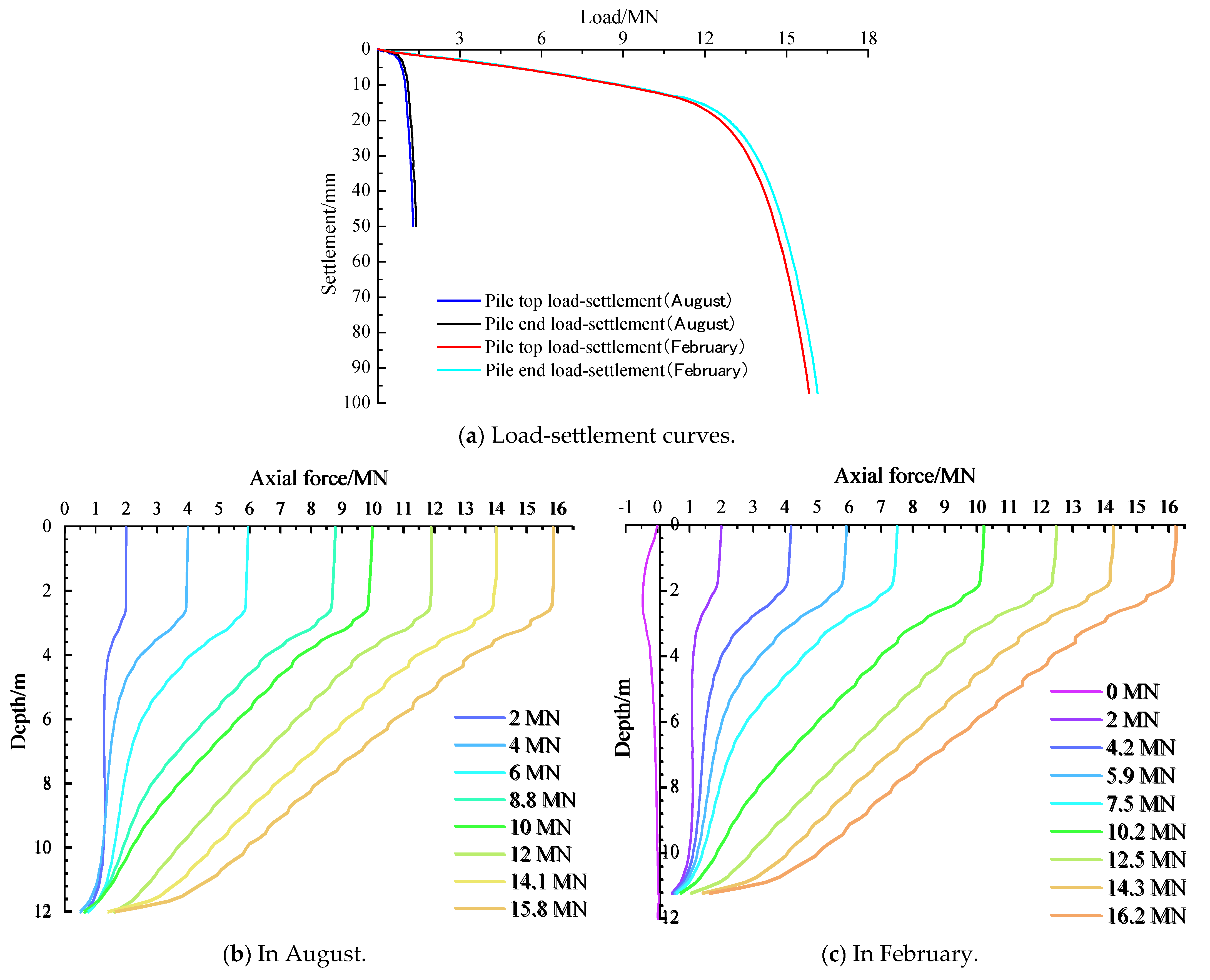
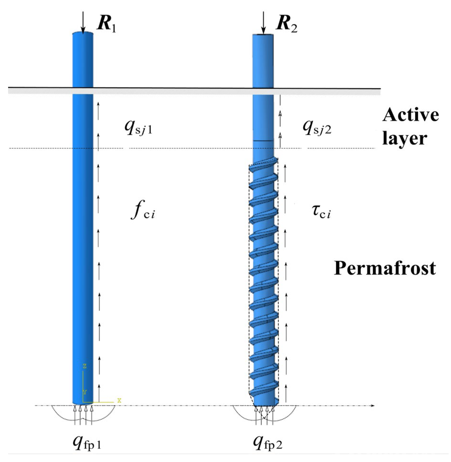
Approximately 90% of the bearing capacity of screw piles in permafrost regions results from the mechanical bonding between pile side’s concrete and the permafrost soil. The seasonally active layer has a minimal impact on the pile’s bearing capacity, and the bearing capacity of the pile’s body is stable throughout the year.
(2)
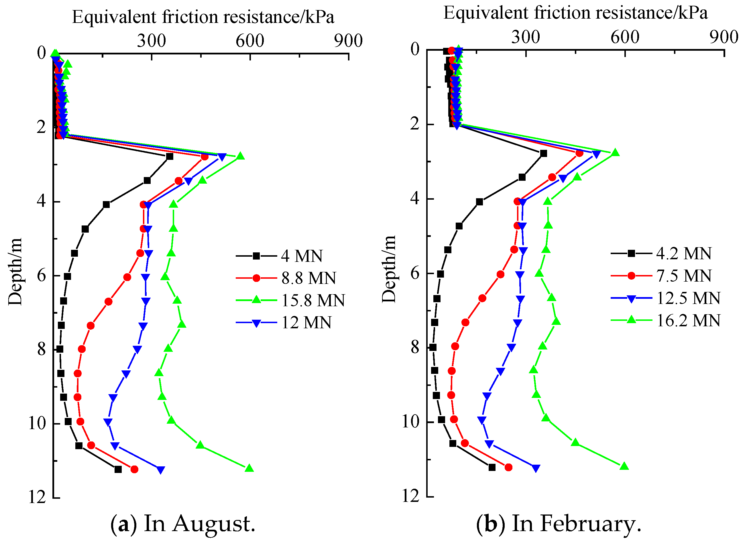
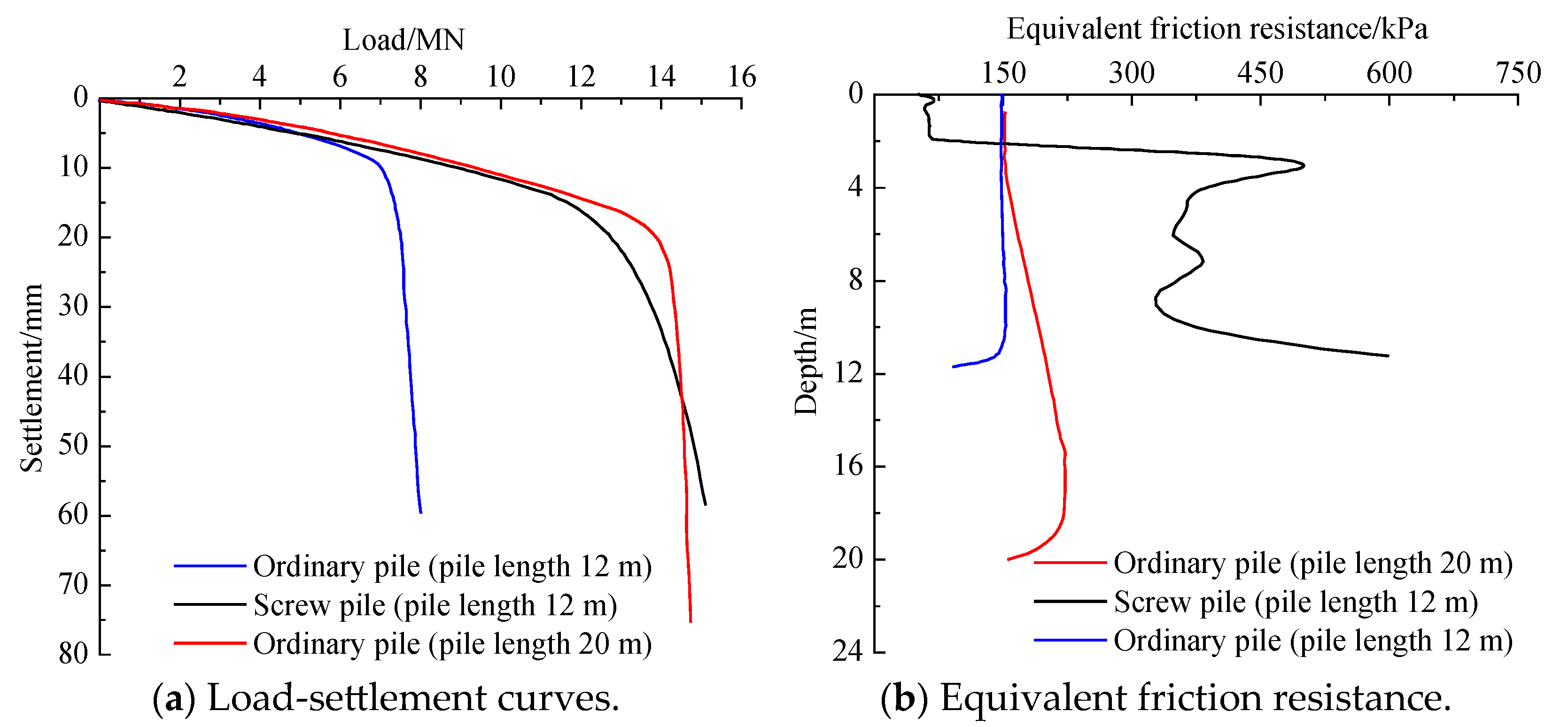
The equivalent friction resistance of screw piles is far greater than that of conventional cast-in-place piles when used in permafrost regions. The screw pile and the soil occlude each other, resulting in a higher equivalent friction resistance of the pile’s side at the beginning and the end of the thread than that of the conventional pile type, which is significantly different from the conventional pile type.
(3)
When the pile reaches the ultimate bearing capacity, the plastic zone of the pile’s side is connected, and the soil around the pile is undergoing shear. Using the improved formula to calculate the vertical bearing capacity of a single pile provides a conservative and practical estimate of the design value of the bearing capacity of a single pile in engineering practice.

Author Contributions

Conceptualization, T.L.; original draft preparation, J.L., X.D., C.G. and W.Z.; review and editing, T.L., C.G. and D.J.; funding acquisition, T.L., J.L. and X.D. All authors have read and agreed to the published version of the manuscript.

Funding

This work was supported by the Youth Science and Technology Foundation of Gansu Province, No. 24JRRA267; the Young Doctor Support Program of Department of Education of Gansu Province, No. 2024QB-048; and the Research Fund of China Railway Engineering Corporation Scientific Research Institute, No. 2023-major project-01-08.

Institutional Review Board Statement

Not applicable.

Informed Consent Statement

Not applicable.

Data Availability Statement

The original contributions presented in this study are included in the article. Further inquiries can be directed to the corresponding author.

Conflicts of Interest

Authors Tao Liu and Jun Lv was employed by the Power China Guiyang Engineering Corporation Limited. Author Xuyan Deng was employed by the Power China Engineering Corporation of Southwest Headquarters. The remaining authors declare that the re-search was con-ducted in the absence of any commercial or financial relationships that could be construed as a potential conflict of interest.

References

  1. Chen, K.; Yu, Q.; Guo, L.; Luo, X.; Chen, J. Analysis of pile-soil heat transfer process based on field test in permafrost regions. Chin. J. Rock Mech. Eng. 2020, 39, 1483–1492. [Google Scholar]
  2. Chen, K.; Yu, Q.; Guo, L.; Guo, L.; Wen, Z. Artificial cooling of cast-in-place piles in permafrost regions. China J. Highw. Transp. 2020, 33, 104–114. [Google Scholar]
  3. Yu, Q.H.; Zhang, Z.Q.; Wang, G.S.; Guo, L.; Wang, X.; Wang, P.; Bao, Z. Analysis of tower foundation stability along the Qinghai-Tibet Power Transmission Line and impact of the route on the permafrost. Cold Reg. Sci. Technol. 2016, 121, 205–213. [Google Scholar] [CrossRef]
  4. Lukpanov, R.E.; Yenkebayev, S.B.; Tsigulyov, D.V. Assessment of the bearing capacity of piles in soil, determined by static and dynamic load tests. Eng. J. Satbayev Univ. 2021, 143, 252–260. [Google Scholar] [CrossRef]
  5. Tiutkin, O.; Radkevych, A.; Dubinchyk, O.; Kharchenko, V. Parametric analysis of a strain state of a soil base strengthened with vertical elements. Min. Miner. Depos. 2024, 18, 104–112. [Google Scholar] [CrossRef]
  6. Polishchuk, A.I.; Maksimov, F.A. Improving the Design of Screw Piles for Temporary Building Foundations. Soil Eng. Found. 2016, 53, 282–285. [Google Scholar] [CrossRef]
  7. Malik, A.A.; Kuwano, J.; Tachibana, S.; Maejima, T. End bearing capacity comparison of screw pile with straight pipe pile under similar ground conditions. Acta Geotech. 2017, 12, 415–428. [Google Scholar] [CrossRef]
  8. Li, C.; Chen, J.; Wu, Q.; Xia, X.H.; Wang, J.H. Bearing mechanism and calculation method of screw pile. J. Shanghai JiaoTong Univ. 2010, 44, 726–730. [Google Scholar]
  9. Qian, J.; Chen, H.; Jia, P.; Huang, M.S.; Hu, Y.Y. Experimental study of mechanical behaviours of grouting-screw pile interface. Chin. J. Rock Mech. Eng. 2013, 32, 1744–1749. [Google Scholar]
  10. Zhou, Y.; Xiao, S.; Xu, J.; Hu, Y.Y. Model test on vertical bearing capacity of variable cross-section thread piles. Rock Soil Mech. 2017, 38, 747–754. [Google Scholar]
  11. Ma, W.; Wang, D. Mechanics of Frozen Soil; Science Press: Beijing, China, 2014. [Google Scholar]
  12. Xu, X.; Wang, J.; Zhang, L. Frozen Soil Physics; Science Press: Beijing, China, 2010; pp. 82–90. [Google Scholar]
  13. Mahedi, M.; Satvati, S.; Cetin, B.; Daniels, J.L. Chemically induced water repellency and the freeze-thaw durability of soils. J. Cold Reg. Eng. 2020, 34, 04020017. [Google Scholar] [CrossRef]
  14. Wu, Y.P.; Wang, H.; Wang, N. Experimental method of ultimate bearing capacity of pile foundation in permafrost region. China J. Highw. Transp. 2018, 31, 38–45. [Google Scholar]
  15. Guo, C.; Wu, Y. Effects of solar radiation and global warming on bearing capacity of single pile in permafrost region. Chin. J. Rock Mech. Eng. 2014, 33 (Suppl. 1), 3306–3311. [Google Scholar]
  16. Wu, Y.; Su, Q.; Guo, C.; Zhu, Y.L.; Zhang, L.X.; Zhao, S.Y. Nonlinear Analysis of ground refreezing processfor pile group bridge foundation in permafrost. China Civ. Eng. J. 2006, 39, 78–84. [Google Scholar]
  17. Wu, Y.; Guo, C.; Pan, W.; Zhao, S.Y.; Zhang, L.X. Influences of refreezing process of ground on bearing capacity of single pile and bridge construction in permafrost. Chin. J. Rock Mech. Eng. 2004, 23, 4229–4233. [Google Scholar]
  18. Wang, X.; Jiang, D.; Liu, D.; He, F. Experimental study of bearing characteristics of large-diameter cast-in-place bored pile under non-refreezing condition in low-temperature permafrost ground. Chin. J. Rock Mech. Eng. 2013, 32, 1807–1812. [Google Scholar]
  19. Wang, X.; Jiang, D.; Zhao, X.; Shi, C.S.; Wang, C.H. An experimental study on refreezing characteristics of large-diameter bored pile in different permafrost areas of the Qinghai-Tibet plateau. Chin. J. Rock Mech. Eng. 2004, 23, 4206–4211. [Google Scholar]
  20. JGJ 106-2003; Ministry of Construction of the People’s Republic of China. Technical Code for Testing of Building Foundation Piles. China Architecture & Building Press: Beijing, China, 2004.
  21. Xu, L. Study on the Test and the Load-Bearing Characteristics of Half-Screw Pile. Master’s Thesis, Hefei University of Technology, Hefei, China, 2013. [Google Scholar]
  22. JGJ 118-2011; Ministry of Housing and Urban-Rural Development of the People’s Republic of China. Code for Design of Soil and Foundation of Buildings in Frozen Soil Region; China Architecture & Building Press: Beijing, China, 2012.
Figure 1. Schematic diagram of screw pile in permafrost region.
Applsci 15 07416 g001
Figure 2. The particle size distribution curve.
Applsci 15 07416 g002
Figure 3. Test equipment system: (a) Model pile, low-temperature test chamber, and loading system. (b) Loading displacement and pressure acquisition system.
Applsci 15 07416 g003
Figure 4. Load-settlement curves of two types of piles under model tests.
Applsci 15 07416 g004
Figure 5. Axial force and equivalent friction resistance of model pile: (a) Ordinary pile; (b) screw pile.
Applsci 15 07416 g005aApplsci 15 07416 g005b
Figure 6. Numerical simulation and verification.
Applsci 15 07416 g006
Figure 7. Calculation model’s boundary conditions and parameters.
Applsci 15 07416 g007aApplsci 15 07416 g007b
Figure 8. The influence curves of temperature on the shear characteristics of the contact surface.
Applsci 15 07416 g008
Figure 9. Load-settlement curves and axial force curves in August and February.
Applsci 15 07416 g009
Figure 10. Equivalent frictional resistance curves under loading for two different seasons.
Applsci 15 07416 g010
Figure 11. Equivalent plastic strain zone when loading.
Applsci 15 07416 g011
Figure 12. Comparison of load-settlement curves and equivalent friction resistance of different piles.
Applsci 15 07416 g012
Figure 13. A schematic diagram of the calculation method of the code.
Applsci 15 07416 g013
Figure 14. Comparison of screw pile bearing capacity by different methods.
Applsci 15 07416 g014
Table 1. Calculation parameters.
MaterialsModulus of Elasticity/MPaPoisson RatioCohesion/kPaAngle of Internal Friction/°Soil Weight/

(kN·m−3)
soil3400.4065.40.819
pile72,0000.33 22
Disclaimer/Publisher’s Note: The statements, opinions and data contained in all publications are solely those of the individual author(s) and contributor(s) and not of MDPI and/or the editor(s). MDPI and/or the editor(s) disclaim responsibility for any injury to people or property resulting from any ideas, methods, instructions or products referred to in the content.

