Article

Robust Model-Free Control for MMC Inverters in Cold Ironing Systems

1
Département de Physique, Faculté des Sciences et Techniques, Université de Nouakchott, Nouakchott BP 5026, Mauritania
2
Institut de Recherche en Energie Electrique de Nantes Atlantique, IREENA, Nantes University, UR 4642, 37 Bd de l’université, 44600 Saint-Nazaire, France
3
Logistics Engineering College, Shanghai Maritime University, New Harbor City, Shanghai 201306, China
*
Author to whom correspondence should be addressed.
Appl. Sci. 2025, 15(13), 7343; https://doi.org/10.3390/app15137343 (registering DOI)
Submission received: 30 May 2025 / Revised: 25 June 2025 / Accepted: 28 June 2025 / Published: 30 June 2025

Abstract

Power quality is a key issue in cold ironing (CI) systems, where a stable, clean power supply is essential to meet the needs of moored vessels. According to IEC/ISO/IEEE 80005-1, these systems must deliver high power at standardized voltages (6.6 kV or 11 kV) with minimal harmonic distortion in the presence of vessel load variability. This study proposes a model-free control strategy based on an intelligent proportional–integral (iPI) corrector with adaptive gain, applied to a three-phase modular multilevel converter (MMC) equipped with an LC filter. This architecture, adapted to distributed infrastructures, reduces the number of transformers required while guaranteeing high output voltages. The iPI strategy improves system robustness, dynamically compensates for disturbances, and ensures better power quality. A comparative analysis of three control strategies, proportional–integral (PI), intelligent proportional–integral (iPI), and intelligent proportional–integral adaptive (iPIa), performed in MATLAB/Simulink and complemented by experimental tests on the OPAL-RT platform, revealed a significant THD reduction of 1.18%, in accordance with the IEC/ISO/IEEE 80005-1 standard. These results confirm the effectiveness of the proposed method in meeting the requirements of CI systems.

1. Introduction

The maritime transport is one of the most widely used means in global trade, accounting for around 80% of international exchanges. However, it is also a major source of pollutant emissions, particularly due to the use of auxiliary engines when ships are docked. In other words, for each kWh of electrical energy produced by onboard generators, a ship can emit up to 0.7 kg of greenhouse gases (GHGs) [1]. For example, a ship with a capacity of 8500 Twenty-Foot Equivalent Units (TEUs) can consume up to 12 tons of fuel daily, resulting in the emissions of over 37 tons of CO2 per day [2]. These emissions include greenhouse gases (CO2, SOx, NOx) and fine particles, contributing to air pollution and the deterioration of air quality in port areas. This makes reducing pollutant emissions a priority issue for the maritime industry.
In the face of these challenges, the International Maritime Organization (IMO) and the European Commission must implement measures to reduce these pollutant emissions in ports, as set out in regulations such as European Directive 2005/33/EC [3]. One of the solutions being considered to mitigate these impacts, shore-side electrification, also known as “cold ironing” or “shore power”, stands out as a promising technology. This approach allows ships to connect to an onshore power supply, allowing them to operate without running their auxiliary engines. It represents a significant step towards cleaner and more sustainable ports. Shutting down the ship’s generators can reduce combustion emissions by up to 90% during their stay in port [4]. Shore-side electrification involves connecting the ship to a land-based electrical network, as shown in Figure 1. Once a ship has docked, it no longer requires propulsion energy. However, several systems remain operational, including ventilation, heating and cooling systems, various auxiliary pumps, and certain control systems. These systems have a significant impact on energy consumption.
Traditionally, this energy is provided by onboard generators, running on diesel and emitting greenhouse gases. However, by connecting ships to a land-based electrical network, their auxiliary engines can be shut down while their systems remain operational. This eliminates emissions during their stay at the port, leading to a significant reduction in environmental impact [5].
As a result, powering these systems requires high power levels and voltages of 6.6 kV or 11 kV, depending on the IEC/ISO/IEEE 80005-1 [6] standard for certain types of ships. This high-power demand is associated with a significant number of transformers. In [7,8,9,10,11], shore power system topologies are classified into three groups: centralized distribution, decentralized distribution, and distributed DC, as shown in Figure 2.

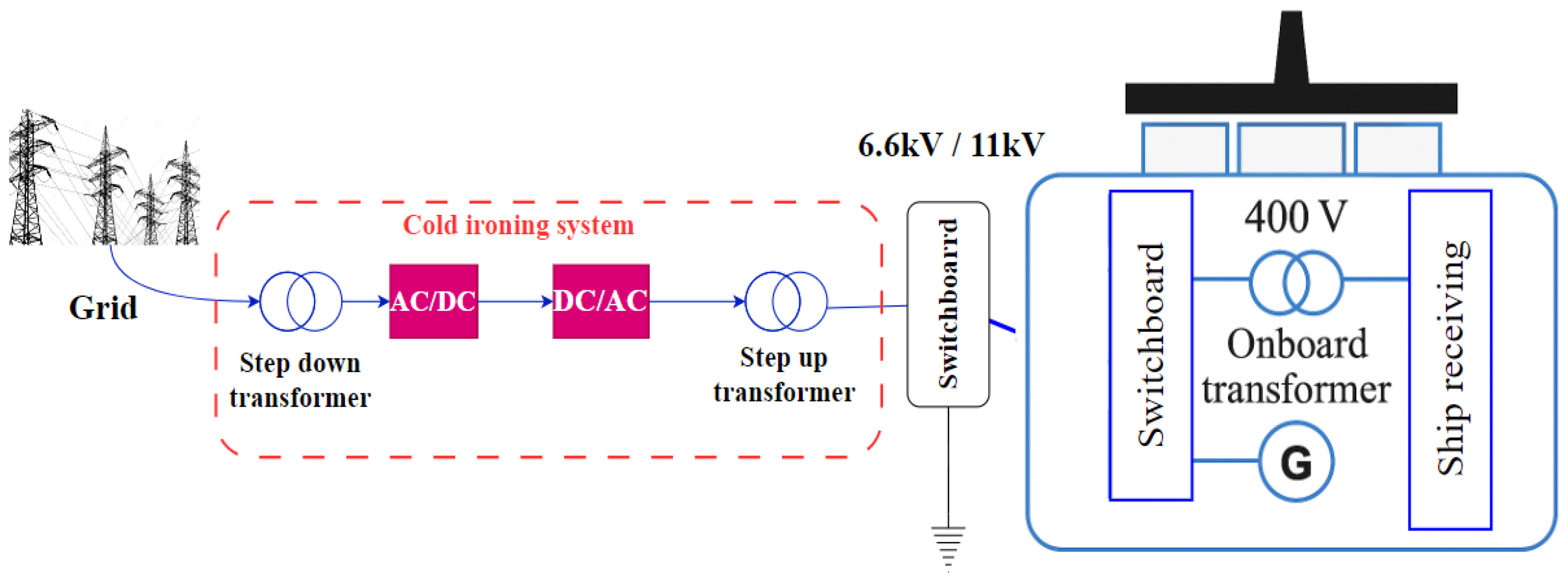
1.1. Centralized Distribution

This topology consists of a single static converter and double busbars, enabling ships to connect to either 50 Hz or 60 Hz, as illustrated in Figure 2a. However, this topology has one drawback: in the event of a converter malfunction, all docks connected to it will lose electricity, with only those linked to the land network remaining accessible.

1.2. Decentralized Distribution

Figure 2b shows a topology that uses multiple converters in parallel. The advantage of this method is that it ensures each ship operates independently. In other words, if one converter fails, it does not prevent other ships from being supplied with power. However, this topology is more expensive, as it requires many transformers and inverters.

1.3. DC Distribution

As shown in Figure 2c, the main advantage of this topology over other typologies is its flexibility in integrating DC power sources, such as fuel cells, renewable energy sources (e.g., solar panels), and battery storage systems. Power transfer process in this topology occurs in three steps: from the grid to the transformer, then to the rectifier, and finally from the rectifier to the DC bus.
To ensure efficient shore power electrification, the energy generated at the dock must be clean, and the shore power supply must be able to provide sufficient, reliable, and stable energy to power all required ship systems. However, integrating these systems poses several technical challenges, particularly due to the variety of voltages and frequencies used by ships. Indeed, power systems vary based on geographical regions and ship types. Some ships operate at low voltage (400 V or 690 V, at 50 Hz or 60 Hz) in accordance with the IEC/ISO/IEEE 80005-3 [12] (low-voltage standard), while others require high voltage (6.6 kV or 11 kV, at 50 Hz or 60 Hz) in accordance with IEC/ISO/IEEE 80005-1 high-voltage standard.
This heterogeneity means that port infrastructure must integrate frequency converters and transformers that can adapt power to the specific needs of ships. Additionally, fluctuating loads require solutions that can maintain network stability and power quality. These fluctuations generate a total harmonic distortion (THD) due to electronic equipment and nonlinear loads, which can directly affect the performance and lifespan of onboard equipment.
International standards, such as IEC/ISO/IEEE 80005-1, impose a THD below 4% in order to ensure a stable and compliant power supply. To meet these standards, researchers are exploring various control strategies that are designed to minimize THD at the Point of Common Coupling (PCC) and ensure fast disturbance rejection, regardless of the type of load or fluctuations in parameters. THD and disturbance rejection are considered key performance indicators for control methods.
As illustrated in Figure 1, several studies on power converter control have been proposed to improve voltage regulation in decentralized generation (DG) systems. Control architectures typically consist of an inner current loop and an outer voltage loop [13,14,15]. This structure allows both current and voltage regulation [16]. Various control techniques have been investigated, including classical control methods [17,18], backstepping [19], and sliding mode control [20,21].
The proportional–integral (PI) classical control is widely used due to its simplicity and effectiveness. However, its performance is limited under critical loads due to the need for linearization around the operating point [22], which can reduce the stability margin of the system and lead to stability issues on a large scale, as well as saturation issues. To overcome these limitations, different techniques have been proposed [22,23]. In [22], a fractional PI controller was developed to enhance disturbance rejection and reduce voltage harmonic distortion (THD). In [23], a fractional Proportional-Resonant (PR) controller was introduced to eliminate steady-state errors and phase shift, thereby improving the accuracy of periodic reference signals.
Backstepping control, which is based on a recursive approach, can be used to stabilize complex nonlinear systems by constructing successive control laws from hierarchical subsystems [24,25]. However, this method becomes increasingly complex with system order and is highly dependent on the model, which can compromise its performance in the presence of uncertainties [26,27]. The backstepping control method is robust against parameter variations, whereas sliding mode control is susceptible to chattering effects [28,29]. Consequently, an adaptive approach to these control strategies is recommended to improve performance and resilience in the face of modeling uncertainties and load fluctuations [30].
Sliding mode control (SMC), on the other hand, is renowned for its robustness against disturbances and uncertainties thanks to the dynamics imposed on a predefined sliding surface [31,32]. However, chattering can occur, which can damage the material, and it is sensitive to the choice of surface and input limitations that are not considered in conventional approaches [32,33]. Finally, model-based predictive control (MPC) offers a powerful framework for anticipating system evolution and optimizing control actions while respecting constraints [34,35]. Nevertheless, real-time implementation remains challenging due to computational complexity, dependence on an accurate model, and difficulty in tuning cost functions [36,37,38].
This study proposes the use of a modular multilevel converter (MMC) to achieve output voltage and power and reduce the number of transformers required in the topology presented in Figure 2b. An ultra-local adaptive control method has also been introduced to enhance the quality of the power supplied by the converter. This approach relies on an intelligent adaptive PI (iPIa) controller that adjusts its gain dynamically to improve disturbance rejection. Unlike traditional methods, this model-free control does not depend on the system model.
Key features of this paper:
  • Application of a robust model-free control approach for the MMC converter in shore power electrification systems.
  • Comparison with classical controllers to highlight the benefits of model-free control in terms of performance and robustness.
  • Validation through simulations in Simulink, demonstrating improvements in THD, dynamic response, and stability.
This paper is structured as follows:
  • Section 2 describes and models the MMC converter.
  • Section 3 presents the proposed control strategies.
  • Section 4 evaluates and analyzes the effectiveness of the proposed control method using MATLAB/Simulink R2017a simulations.
  • Section 5 concludes this study.

2. Description and Modeling of the MMC Converter

To ensure shore power systems meet the high power and voltage demands of ships, selecting a suitable converter for high-power generation and transmission is crucial. This has led to the adoption of the MMC converter in such systems. Due to its modularity, the MMC converter is advantageous because it can adapt to varying voltage and power levels, unlike traditional topologies, which are typically limited to three or five levels in medium-voltage applications. Increasing the number of levels in conventional converters was restricted by the complexity of possible topologies [39].

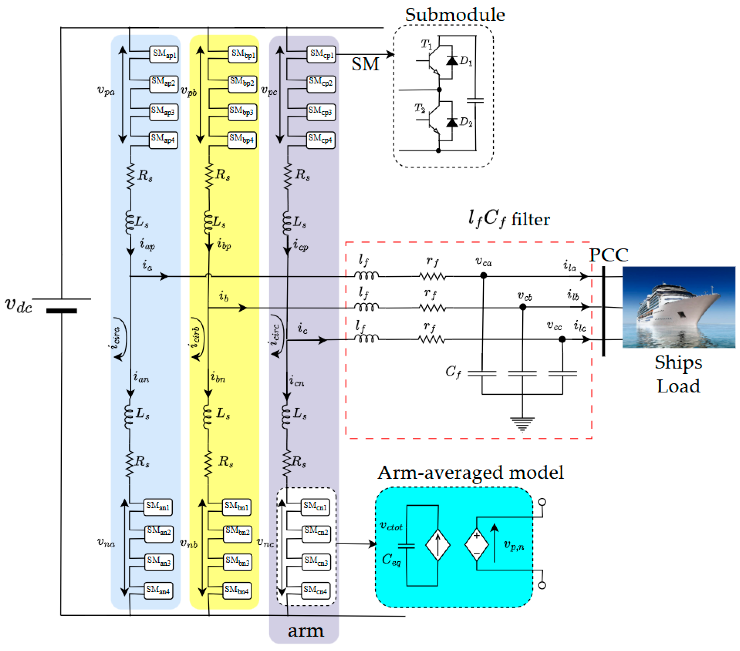
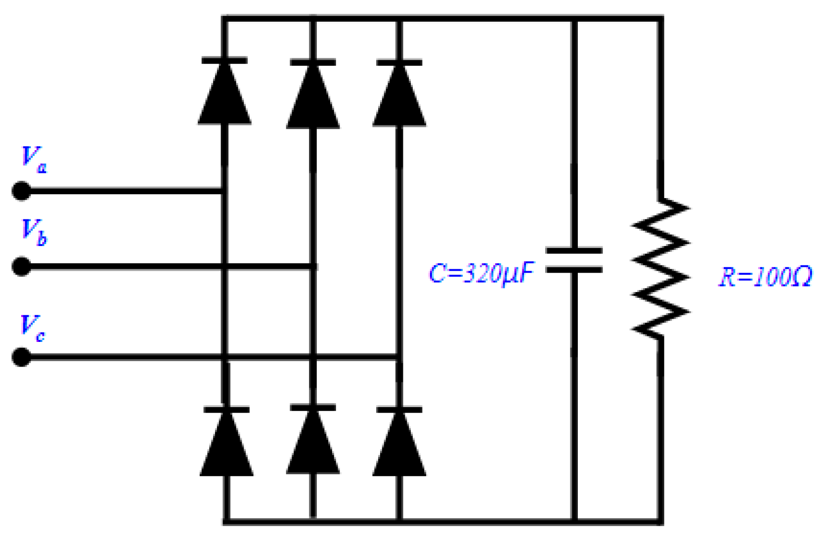
2.1. Description of the MMC Converter

This study focuses on the topology of a three-phase MMC (as an inverter), as shown in Figure 3. Each arm of the MMC is averaged using a switching function concept of an H-bridge converter. In this configuration, isolated voltage sources are replaced by floating capacitors, requiring precise voltage regulation to avoid undesirable voltage fluctuations across active components. Each arm of the MMC inverter contains identical submodules connected in series with a smoothing inductor. Ls and Rs represent the inductance and the resistance of the arm, through which the internal currents of an inverter arm are symbolized by ip and in, corresponding to the top and bottom part of the half-arms, respectively.
In particular, the average voltage across the capacitor in each submodule, denoted vc, is equal to v d c N , where v d c is the DC bus voltage, and N represents the number of submodules per half-arm. It is crucial to control the voltage of all these capacitors to avoid any sudden voltage variations across the active components, and to ensure that the operating voltage remains below their rated voltage.
Internal currents are described by i d c for direct current and i a b c for alternating current. This configuration enables bidirectional power conversion. The inverter is connected to a load via an output LfCf filter, while the v d c voltage is kept constant to ensure system control.

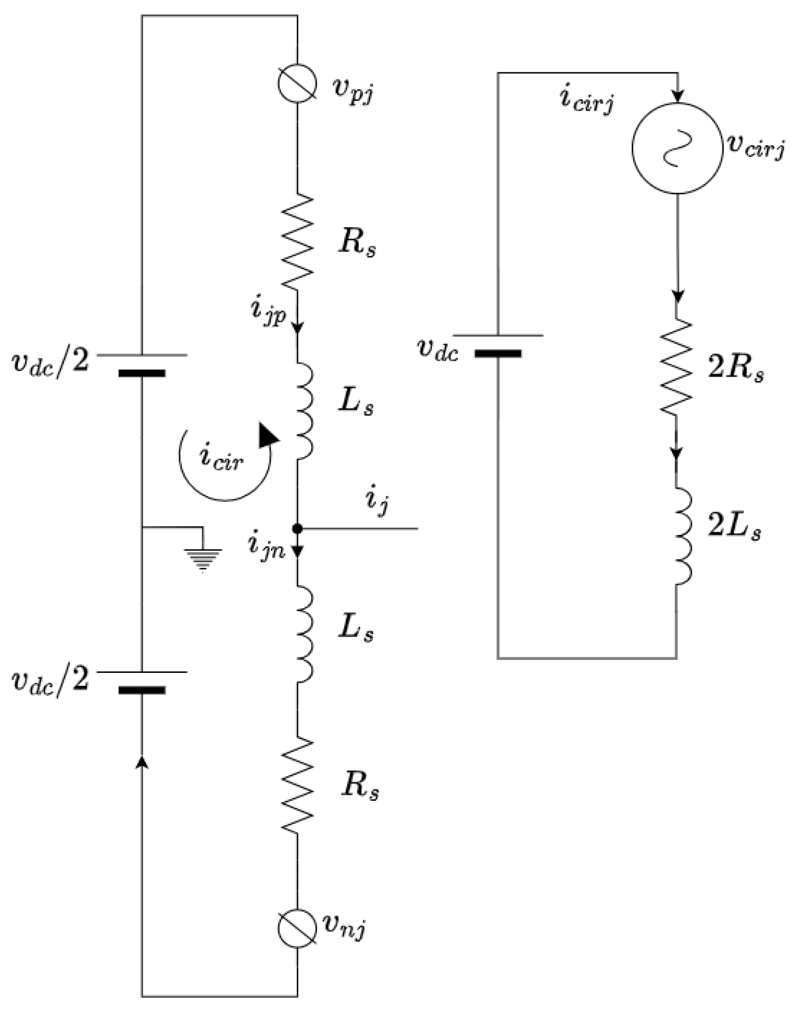
2.2. Modeling of the MMC Converter

Modeling the modular multilevel converter (MMC) is a crucial step in analyzing and optimizing power electronics systems used in high-voltage transmission applications. Throughout the modeling process, we assume that the output current is equally divided between the upper and lower arms and that switching losses for the power devices are not considered. The total output voltages of the SMs in the lower (or upper) arm of each phase can be represented as controlled voltage sources vpj (or vnj), as shown in Figure 4. Applying Kirchhoff’s law to phase j (where j = a, b, c), we derive circulating current i c i r j and voltage v c i r j in Equations (1) and (2):
i c i r j t = i p j t + i n j t 2
v c i r j t = v p j t + v n j t
Lower and upper lower loops are described by Equations (3) and (4), respectively:
v d c t 2 + v n j t + L s d i n j t d t + R s i n j t l f d i j t d t r f i j t v c j t = 0
v d c t 2 v p j t L s d i p j t d t R s i p j t l f d i j t d t r f i j t v c j t = 0
where
v n j : lower part voltage;
i n j : lower part current;
i p j : upper part current;
v p j : upper part voltage;
l f ,   r f   and   C f are, respectively, the inductance, the resistance and the capacitor of the filter;
i c : the inductor current in abc frame i a , i b , i c ;
v c j : the voltage of the capacitor of phase j;
i l j : the load output current of phase j;
Summing Equations (3) and (4) gives Equation (5) which describes the AC-side dynamics of the Arm Average Model:
v j t v c j t = L e q d i j t d t + R e q i j t
where: i j t = i p j t i n j t , v j t = v n j t v p j t 2 , R e q = r f + R s 2 and L e q = L f + L s 2
Subtracting Equation (3) from (4) gives Equation (6), which describes the DC-side dynamics of the Arm Average Model:
v d c t v c i r j t = 2 L s d   i c i r j t d t + 2 R s   i c i r j t
The MMC equations for the AC and DC part transferred into the d,q frame, using Park transformation matrix, are given by the following equations [40]:
The AC-side dynamics (5) can be decomposed into
v d t v c d t = L e q d i d t d t + R e q i d t L e q ω i q t
v q t v c q t = L e q d i q t d t + R e q i q t + L e q ω i d t
C f d v c d t d t = i d t i l d t + C f ω v c q t
C f d v c q t d t = i q t i l q t C f ω v c d t
With
v c d , v c q : the dq components of the voltage at point PCC;
v d , v q : are the dq components of the voltage inputs of the inverter;
i d , i q : the dq components of the line currents;
i l d , i l q : the components dq of the load currents;
ω : is the angular frequency.
The DC-side Equation (6) is simplified as follows:
v d c t v d c i r t = 2 L s d i d c i r   t d t + 2 R s i d t
v q c t v q c i r t = 2 L s d i q c i r t d t + 2 R s i q t

3. Proposed Control Strategy

Most advanced control strategies require at least partial knowledge of the physical model of the system to be controlled. This is a major drawback, as obtaining these physical equations can be complex. What’s more, the nature of these models is often difficult to exploit, especially if they are partial differential equations [41].
In this study, we use model-free control (MFC). In [42], M. Fliess and J. Join introduced the concept of combining an ultra-local model with the notion of model-free control, thus eliminating the need for mathematical modeling. This control method is based on an ultra-local model that represents only the input–output behavior of the system, as shown in Figure 5. The intelligent proportional–integral (iPI) controller continuously updates its parameters to adapt to the dynamic evolution of the system. It is a key component of this approach as it disregards the model of both Single Input Single Output (SISO) and Multi-Input Multi-Output (MIMO) systems because it uses an ultra-local model expressed in an affine form given by Equation (13), using a specific order, v, as follows:
y v t = F t + α u t
where y v t is the v order derivative of the system output (typically, v is set to 1 or 2), u t is the control signal, α is a constant input so that the magnitude orders of α u t and y v t close, and F t is a corrective coefficient, estimated at each computation step.
Closing the loop using an intelligent PI controller gives the control law expressed by Equation (14):
u t   =   y d v t     F e t   +   k p ε t   +   k i ε t d t       α
where y d v t is the reference, ε t is the tracking error,   k p   and     k i are the tuning gains.
The control law (14) requires the estimation of F(t), noted F e t . In [43], M. Fliess proposed two methods of calculating F e t . In this study, F e t is calculated by Equation (15):
F e t = y v t α u t T e
where Te represents the sampling period.
Equation (14) of the ultra-local model of model-free control shows that there are two parameters that we can adjust: the derivative order v and the parameter α. In this study, we focus on adjusting α to improve the performance of model-free control. The parameter α represents a scaling factor between the time derivative of the output and the input. Until now, its adjustment has been based on an empirical approach. However, in systems subject to large variations in input or output amplitude (whether known or unknown), an initial fixed choice of α may become inadequate.
In our case study, where the maritime loads fluctuate significantly, the dynamic adaptation ∆α of α would allow us to analyze its response to these fluctuations and optimize the robustness of the system, as represented by Equations (16)–(18):
y v t = F t + ( α 0 + Δ α ) u t
u t   =   y d v t     F e t   +   k p ε t   +   k i ε t dt       α 0 + Δ α
F e t = y v t α 0 + Δ α u t T e

3.1. Application to the Studied System

The presence of nonlinear or unbalanced loads leads to the generation of periodic harmonic components in the output voltage waveform. To counteract these effects, we have proposed a control method based on an intelligent proportional–integral (iPI) controller with adaptive gain, while respecting the control objectives. Unlike traditional approaches, the proposed control does not rely on the system model but simply uses the inputs and outputs of the system without needing to know the internal details. This approach has the advantage of an equation that is independent of system parameters, which guarantees a significant rejection of disturbances. This makes our method more flexible and adaptable to real system conditions. Throughout this work, v = 1. The controller design based on the free model is shown in Figure 6. It includes two separate control loops:
  • Outer loop: this loop uses an iPIa to regulate the output voltage and provides the internal current references and uses an iPIa controller.
  • Inner loop: this loop uses a simple Proportional gain controller to generate the converter input control signal.
The application of the proposed control law gives the following reference currents:
i d * = i d F e t + k p ε v d + k i ε v d α 0 + Δ α
i q * = i q F e t + k p ε v q + k i ε v q α 0 + Δ α

3.2. Modulation Technique

One of the technical issues associated with controlling the MMC converter is maintaining the voltage balance at the various submodules at their nominal values. Figure 7 shows the technique used to achieve voltage balancing. The latter is based on measuring the voltages of the capacitors and then sorting them either in ascending or descending order, depending on the direction of the arm currents.
Where r1, r2 are the repetitive sequences, i1, i2, i3, i4 represent the voltage decreased index, and i is the arm current.

3.3. Stability Analysis

If x 1 = i d , u = v c d , applying the delay method on Equation (13) gives Equation (21)
F t = x ˙ 1 α u
With x 1 = x t T e and u = u ( t T e ).
The lag of the control law from Equation (14) is given by Equation (22)
α u = y ˙ d t   F t + k p ε t + k i ε t
where y ˙ d t is the output delay and y ˙ * is the reference derivative.
Subtracting the Equations (13) and (22), we find the Equation (23)
α u u = y ˙ d t y ˙ d t + k p ε t + k i ε t
With ε ˙ = y ˙ d t y ˙ d t , Equation (23) becomes
α u u = ε ˙ t + k p ε t + k i ε t
If the system in closed loop is stable, then in steady state u = u , Equation (24) becomes:
ε ˙ t + k p ε t + k i ε t = 0
u can be approximated by
u = u + T e u ˙
By injecting (26) into (24), we obtain
α T e u ˙ = ε ˙ t + k p ε t + k i ε t
By replacing it in Equation (7), the derivative of the control law can be established by Equation (28)
u ˙ = L e q x ¨ 1 + R e q x ˙ 1 α
Thus, the representation of the system given by Equation (28) can be expressed as follows:
α T e L e q x ¨ 1 + R e q x ˙ 1 α = x ˙ 1 * x ˙ 1 + k p ( x 1 * x 1 ) + k i x 1 * x 1
So, the characteristic equation is
T e L e q s 3 + T e R e q s 2 + k p s + k i = 0
According to Routh’s criterion: the first condition holds T e L e q , T e R e q , k p ,   k i > 0 , and the closed loop system is stable if R e q k p > L e q k i .

4. Simulation Results

In this section, three tests are performed using the MATLAB/Simulink software to evaluate the effectiveness of the proposed control approach. The first test involves parametric variation. The second test focuses on the nonlinear evaluation by measuring the voltage total harmonic distortion (THD). The third test investigates the performance of the proposed control when dealing with a variable load. Table 1 presents the system and controller parameters.

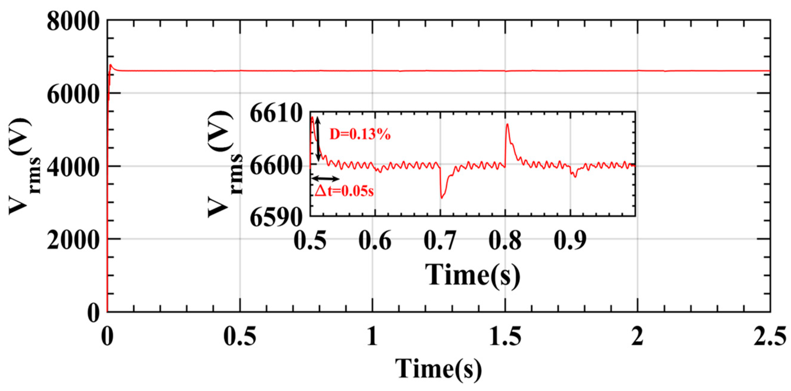
4.1. Test of Ship Load Profile

Figure 8 shows the power evolution over time to analyze the effect of load variations on the proposed method. Vrms voltage variations due to load variations are a well-known problem in the field. In this context, a test of the proposed control was performed to see the effectiveness of the control, as clearly shown in Figure 9. This ability to maintain voltage stability under changing load conditions highlights the robustness and reliability of this control, which is essential to ensure proper system operation as shown on Figure 10.

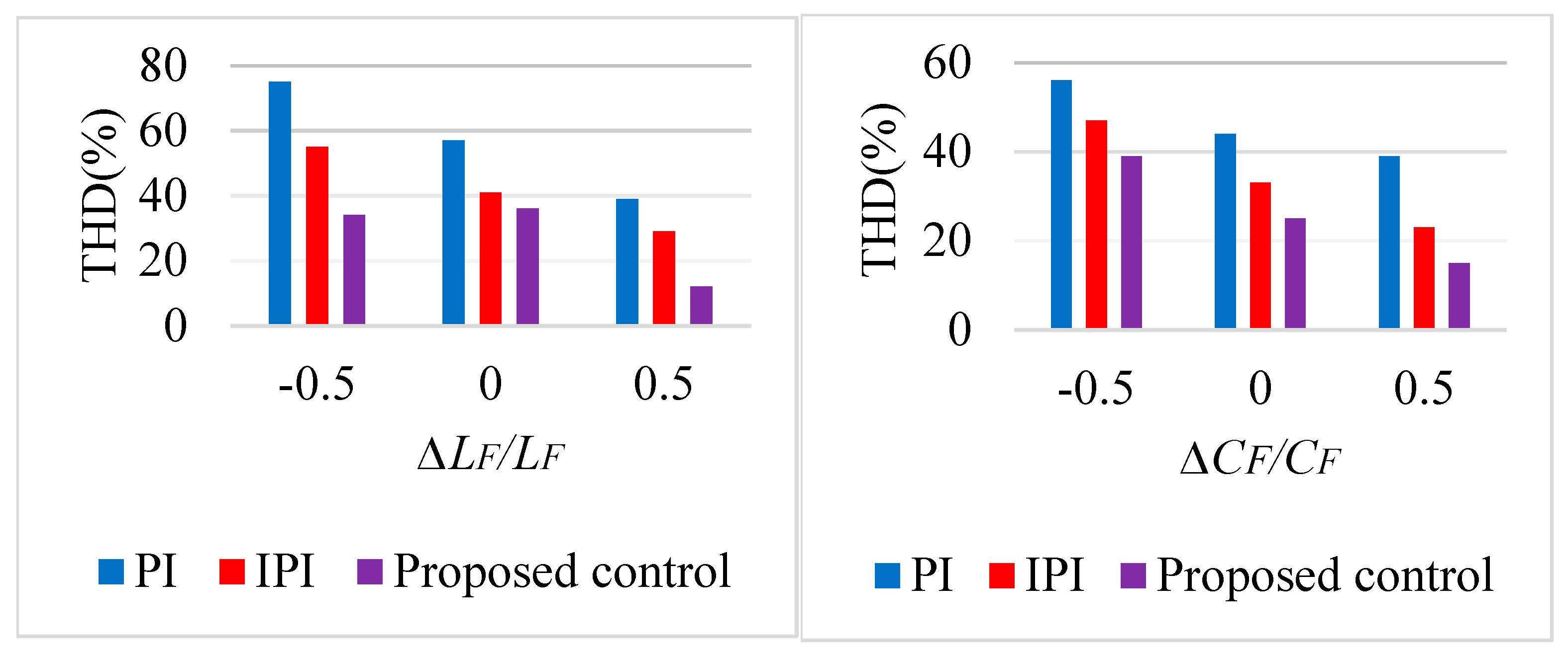
4.2. Robustness Analysis

In this section, parametric robustness tests were performed by varying the filter parameters, lf and Cf. Figure 11 shows the resulting total harmonic distortion (THD) for the three controllers, taking into account variations in the passive filter where lf is set to ±50% of its initial value and Cf is set ±50% of its initial value. The analysis of the THD measurements shows that the proposed (i)PI controller achieves a better THD ratio than the other two controllers. These results highlight the ability of this controller to maintain improved signal quality, even in the face of significant variations in filter parameters.

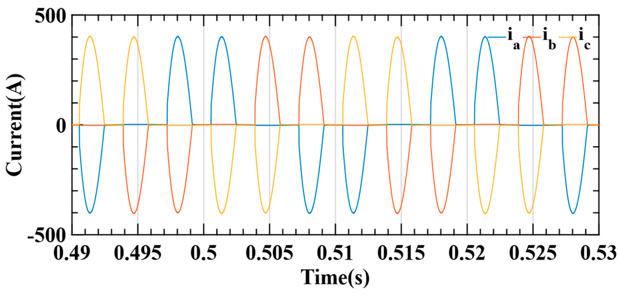
4.3. Nonlinear Loading Conditions

This test is performed in the presence of an extremely disturbing load (a three-phase diode bridge), as shown in Figure 12. The current waveforms associated with this load are shown in Figure 13.
The proposed control method has demonstrated its ability to significantly improve the voltage quality for nonlinear loads, as shown in Figure 14. The analysis of the harmonic distortion rates, comparing PI, (i)PI, and the proposed control, shows values of 1.76%, 1.42% and 1.18%, respectively. These results highlight the remarkable effectiveness of the proposed method in reducing harmonic distortion.

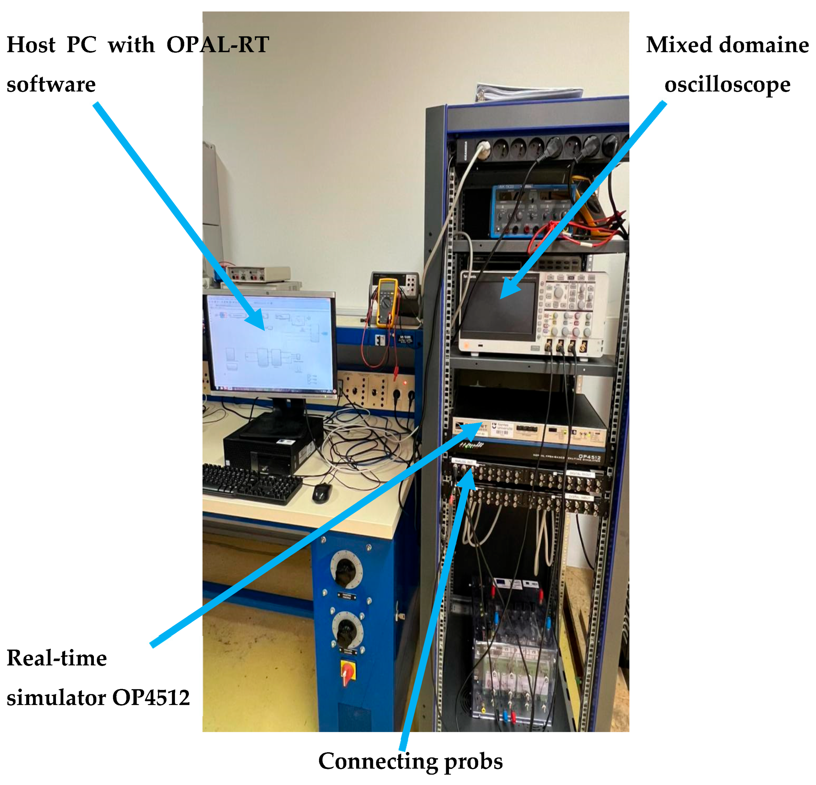
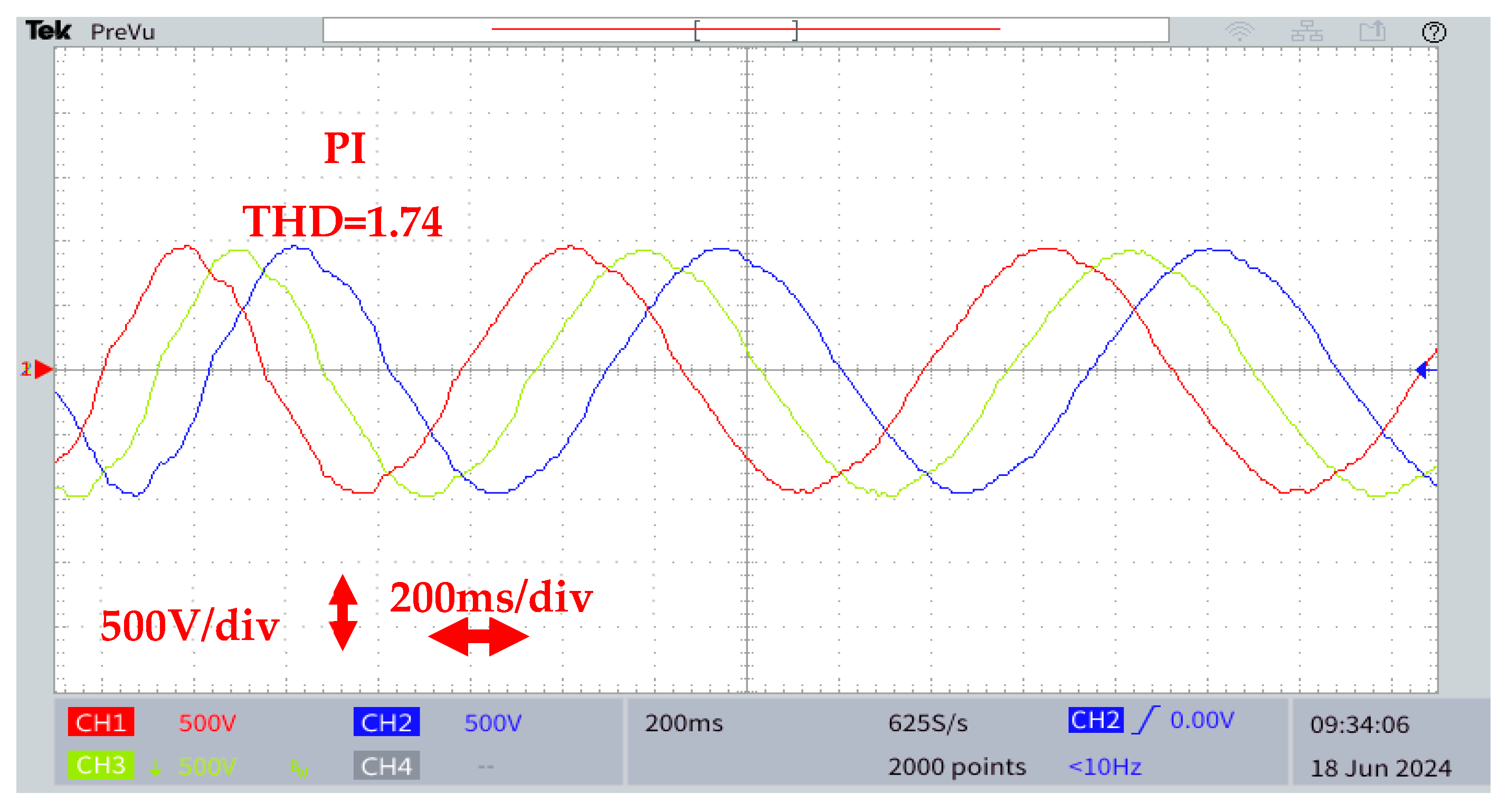
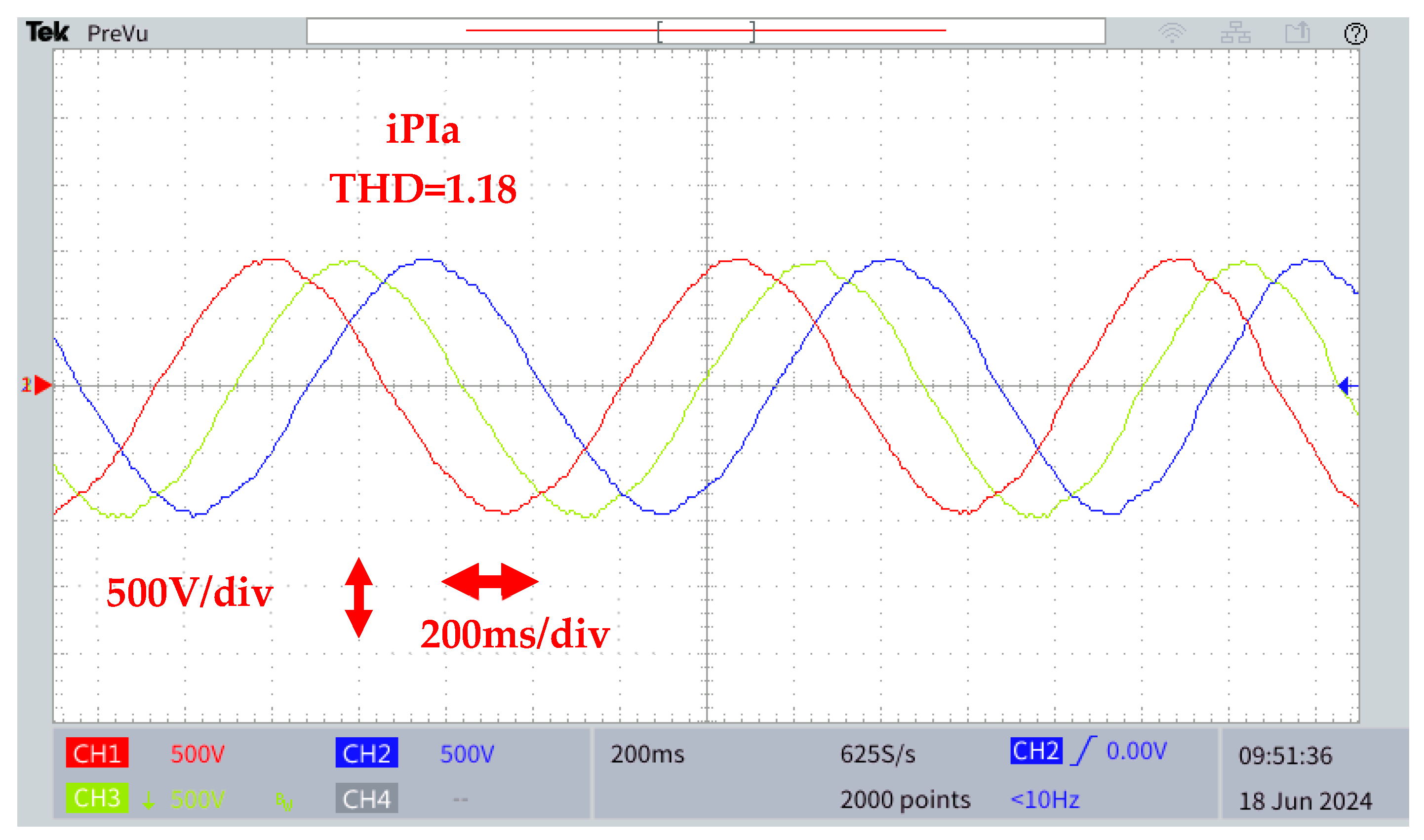
4.4. OPAL-RT Validation Result

To assess the robustness and practical feasibility of the proposed control strategy under nonlinear conditions, a hardware-in-the-loop (HIL) test was performed using the OPAL-RT OP4512 real-time simulation platform. The use of HIL simulation allows the behavior of the system to be observed in real time in a high-fidelity environment representative of real-life conditions. The experimental platform consists of a host PC running RT-LAB v2024.3.3.51 software, a digital oscilloscope for signal visualization, Ethernet TCP/IP communication, computing targets, and I/O boards, as shown in Figure 15. This configuration allows the control strategy to be validated in a realistic context.
This test demonstrated the effectiveness of the proposed method in terms of power quality, with a total harmonic distortion (THD) of 1.18%, compared with 1.42% and 1.76% for the iPI and PI strategies, in the presence of a nonlinear load, as shown in Figure 16.

5. Conclusions

This paper presents a control approach for an MMC inverter equipped with an output LC filter. The key element of this research is the proposal of a control strategy that does not depend on the system model, uses only the system input and output, and does not include any inverter parameters, making it robust. The latter is based on an intelligent proportional–integral ((i)PI) controller with adaptive gain, which enhances its ability to eliminate disturbances.
This paper also presents a detailed description of the MMC system and a comprehensive analysis of the control technique, including a stability study according to Routh’s criterion. To evaluate the effectiveness of this method, a comparative analysis with a conventional PI controller is performed under different operating conditions. Simulation results obtained using the MATLAB/Simulink environment are presented for nonlinear and variable loads. They show a significant improvement in voltage waveform quality and enhanced noise rejection capabilities.
  • Regulating the voltage at the PCC during a variable load.
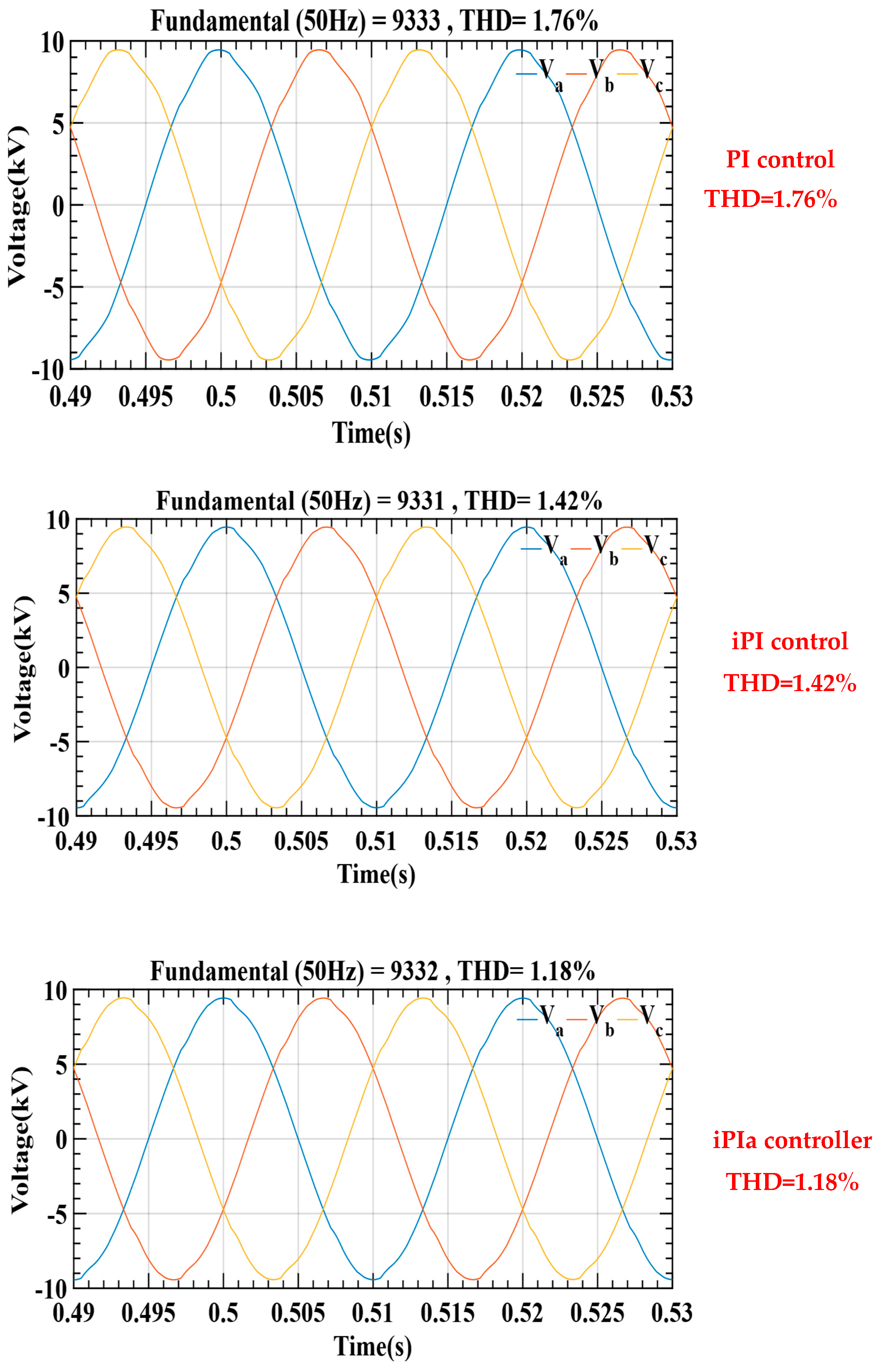
  • Reducing voltage harmonics for a nonlinear load with THD equal to 1.18%.
Comparisons with the association of the proposed method with predictive control (MPC) are important for understanding the performance of the developed control strategy. This reduces dependence on precise models in predictive strategies. Consequently, in-depth comparisons between these methods are important for characterizing and optimizing the performance of the developed controls.

Author Contributions

Conceptualization, A.H.; Methodology, C.A.K.; Software, C.A.K.; Validation, A.H.; Writing—original draft, C.A.K., G.Y. and M.E.-B.; Writing—review & editing, N.A.-A., A.H. and M.A.-A.; Visualization, N.A.-A. and M.A.-A. All authors have read and agreed to the published version of the manuscript.

Funding

This research received no external funding.

Institutional Review Board Statement

Not applicable.

Informed Consent Statement

Not applicable.

Data Availability Statement

The original contributions presented in the study are included in the article, further inquiries can be directed to the corresponding author.

Conflicts of Interest

The authors declare no conflicts of interest.

Abbreviations

MMCModular Multilevel Converter
THDTotal Harmonic Distortion
CICold Ironing
MFCModel-Free Control
GHGGreenHouse Gases
TEUsTwenty-Foot Equivalent Units
DGDecentralized Generation
SMSubModule
iPIintelligent Proportional-Integral
SISOSingle Input Single Output
MIMOMulti-Input Multi-Output
HILHardware-In-the-Loop
PIProportional–Integral
iPIaIntelligent proportional–integral adaptive

References

  1. International Maritime Organization. Site officiel de l’IMO. 2025. Available online: http://www.imo.org/ (accessed on 29 May 2025).
  2. Vancouver Fraser Port Authority. Homepage FR|Vancouver Fraser Port Authority. 2025. Available online: https://www.portvancouver.com/fr (accessed on 29 May 2025).
  3. Smith, R. Directive 2006/54/EC of the European Parliament and of the Council of 5 July 2006. In Core EU Legislation; Macmillan Education UK: London, UK, 2015; pp. 333–345. [Google Scholar] [CrossRef]
  4. Etcher, K. An Introduction to Shore Power. GVHA. 2025. Available online: https://gvha.ca/about-gvha/blog/an-introduction-to-shore-power/ (accessed on 29 May 2025).
  5. Rapport technique, Innovation Maritime. L’électrification des quais au Québec; Réseau MeRLIN et Technopole maritime du Québec: Rimouski, QC, Canada, 2022; Available online: https://www.innovationmaritime.ca/ (accessed on 29 May 2025).
  6. IEC/ISO/IEEE 80005-2012; ICS code: 47.020.60, IEC/ISO/IEEE Utility Connections in Port—Part 1: High Voltage Shore Connection (HVSC) Systems. IEEE: Piscataway, NJ, USA, 2012. [CrossRef]
  7. He, J.; Li, X.; Xu, H.; Zhu, J.; Dai, P.; Chu, H. Review and Discussion on Standards for Shore-to-Ship Power Supply System. In Proceedings of the 4th Annual International Conference on Material Engineering and Application (ICMEA 2017), Wuhan, China, 15–17 December 2017; Volume 146. [Google Scholar]
  8. Baizura Binti Ahamad, N.; Guerrero, J.M.; Su, C.-L.; Vasquez, J.C.V.; Zhaoxia, X. Microgrids Technologies in Future Seaports. In Proceedings of the 2018 IEEE International Conference on Environment and Electrical Engineering and 2018 IEEE Industrial and Commercial Power Systems Europe, EEEIC/I and CPS Europe 2018, Palermo, Italy, 12–15 June 2018; pp. 1–6. [Google Scholar] [CrossRef]
  9. Sciberras, E.A.; Zahawi, B.; Atkinson, D.J.; Juandó, A.; Sarasquete, A. Cold ironing and onshore generation for airborne emission reductions in ports. Proc. Inst. Mech. Eng. Part M J. Eng. Marit. Environ. 2016, 230, 67–82. [Google Scholar] [CrossRef]
  10. Sciberras, E.A. Shipboard Electrification: Emission Reduction and Energy Control. Ph.D. Thesis, Newcastle University, Newcastle upon Tyne, UK, 2016. Available online: https://theses.ncl.ac.uk/jspui/handle/10443/3229 (accessed on 29 May 2025).
  11. Bernacchi, R. Shore-to-ship power: Opportunities and challenges. In MEDports Forum 2019. 2019. Available online: https://medports.org/wp-content/uploads/2019/10/Roberto-BERNACCHI-Shore-to-Ship-Power-ABB-MEDports-FORUM-2019.pdf (accessed on 29 May 2025).
  12. IEC/ISO/IEEE 80005-2014; ICS Code: 47.020.60, Utility Connections in Port—Part 3: Low Voltage Shore Connection (LVSC) Systems. IEEE: Piscataway, NJ, USA, 2014. Available online: https://cdn.standards.iteh.ai/samples/21961/a99297bdae7a4d82b8f355889d528989/IEC-PAS-80005-3-2014.pdf (accessed on 29 May 2025).
  13. Ryan, M.; De Doncker, R.; Lorenz, R. Decoupled control of a 4-leg inverter via a new 4×4 transformation matrix. In Proceedings of the 30th Annual IEEE Power Electronics Specialists Conference, Record, (Cat. No.99CH36321), Charleston, SC, USA, 1 July 1999; pp. 187–192. [Google Scholar] [CrossRef]
  14. Vechiu, I.; Curea, O.; Camblong, H. Transient Operation of a Four-Leg Inverter for Autonomous Applications With Unbalanced Load. IEEE Trans. Power Electron. 2010, 25, 399–407. [Google Scholar] [CrossRef]
  15. Zhou, X.; Tang, F.; Loh, P.C.; Jin, X.; Cao, W. Four-Leg Converters With Improved Common Current Sharing and Selective Voltage-Quality Enhancement for Islanded Microgrids. IEEE Trans. Power Deliv. 2016, 31, 522–531. [Google Scholar] [CrossRef]
  16. Mehrasa, M. Control of Modular Multilevel Converters in High Voltage Direct Current Power Systems. Ph.D. Thesis, University of Beira Interior, Covilhã, Portugal, 2019. Available online: https://scispace.com/pdf/control-of-modular-multilevel-converters-in-high-voltage-4t9494qzsv.pdf (accessed on 29 May 2025).
  17. Shahparasti, M.; Mohamadian, M.; Yazdian, A.; Ahmad, A.A.; Amini, M. Derivation of a Stationary-Frame Single-Loop Controller for Three-Phase Standalone Inverter Supplying Nonlinear Loads. IEEE Trans. Power Electron. 2014, 29, 5063–5071. [Google Scholar] [CrossRef]
  18. Loh, P.C.; Newman, M.; Zmood, D.; Holmes, D. A comparative analysis of multiloop voltage regulation strategies for single and three-phase UPS systems. IEEE Trans. Power Electron. 2003, 18, 1176–1185. [Google Scholar] [CrossRef]
  19. Wai, R.; Lin, C.; Wu, W.; Huang, H. Design of backstepping control for high-performance inverter with stand-alone and grid-connected power-supply modes. IET Power Electron. 2013, 6, 752–762. [Google Scholar] [CrossRef]
  20. Bayhan, S.; Trabelsi, M.; Abu-Rub, H.; Malinowski, M. Finite-Control-Set Model-Predictive Control for a Quasi-Z-Source Four-Leg Inverter Under Unbalanced Load Condition. IEEE Trans. Ind. Electron. 2017, 64, 2560–2569. [Google Scholar] [CrossRef]
  21. Gałecki, A. Particle swarm optimization of the multioscillatory LQR for a three-phase grid-tie converter. Przeglad Elektrotech. 2018, 94, 43–48. [Google Scholar] [CrossRef]
  22. Mohagheghi, S.; Del Valle, Y.; Venayagamoorthy, G.K.; Harley, R.G. A Proportional-Integrator Type Adaptive Critic Design-Based Neurocontroller for a Static Compensator in a Multimachine Power System. IEEE Trans. Ind. Electron. 2007, 54, 86–96. [Google Scholar] [CrossRef]
  23. Heredero-Peris, D.; Chillón-Antón, C.; Sánchez-Sánchez, E.; Montesinos-Miracle, D. Fractional proportional-resonant current controllers for voltage source converters. Electr. Power Syst. Res. 2019, 168, 20–45. [Google Scholar] [CrossRef]
  24. Zhao, L.; Li, Z.; Li, H.; Liu, B. Backstepping integral sliding mode control for pneumatic manipulators via adaptive extended state observers. ISA Trans. 2024, 144, 374–384. [Google Scholar] [CrossRef] [PubMed]
  25. Gong, X.; Fu, W.; Bian, X.; Fei, J. Adaptive Backstepping Terminal Sliding Mode Control of Nonlinear System Using Fuzzy Neural Structure. Mathematics 2023, 11, 1094. [Google Scholar] [CrossRef]
  26. Liu, X.; Qiu, L.; Rodriguez, J.; Wu, W.; Ma, J.; Peng, Z.; Wang, D.; Fang, Y. Neural Predictor-Based Dynamic Surface Predictive Control for Power Converters. IEEE Trans. Ind. Electron. 2022, 70, 1057–1065. [Google Scholar] [CrossRef]
  27. Zandi, O.; Poshtan, J. Voltage control of DC–DC converters through direct control of power switches using reinforcement learning. Eng. Appl. Artif. Intell. 2023, 120, 105833. [Google Scholar] [CrossRef]
  28. Zheng, L.; Jiang, F.; Song, J.; Gao, Y.; Tian, M. A Discrete-Time Repetitive Sliding Mode Control for Voltage Source Inverters. IEEE J. Emerg. Sel. Top. Power Electron. 2018, 6, 1553–1566. [Google Scholar] [CrossRef]
  29. Kumar, N.; Saha, T.K.; Dey, J. Sliding-Mode Control of PWM Dual Inverter-Based Grid-Connected PV System: Modeling and Performance Analysis. IEEE J. Emerg. Sel. Top. Power Electron. 2016, 4, 435–444. [Google Scholar] [CrossRef]
  30. Zangeneh Bighash, E.; Sadeghzadeh, S.M.; Ebrahimzadeh, E.; Blaabjerg, F. Adaptive-Harmonic Compensation in Residential Distribution Grid by Roof-Top PV Systems. IEEE J. Emerg. Sel. Top. Power Electron. 2018, 6, 2098–2108. [Google Scholar] [CrossRef]
  31. Uddin, W.; Zeb, K.; Adil Khan, M.; Ishfaq, M.; Khan, I.; Islam, S.U.; Kim, H.-J.; Park, G.S.; Lee, C. Control of Output and Circulating Current of Modular Multilevel Converter Using a Sliding Mode Approach. Energies 2019, 12, 4084. [Google Scholar] [CrossRef]
  32. Jin, Y.; Cong, H.; Yang, Y.; Ji, A.; Fan, M.; Li, X.; Rodriguez, J. Finite-Control-Set Predictive Sliding Mode Control for LC-filtered Single-Phase Inverters. In Proceedings of the 2024 IEEE 10th International Power Electronics and Motion Control Conference (IPEMC 2024-ECCE Asia), Chengdu, China, 17–20 May 2024; pp. 1–7. [Google Scholar]
  33. Jouybary, H.S.; Khaburi, D.A.; El Hajjaji, A.; Mabwe, A.M. Optimal Sliding Mode Control of Modular Multilevel Converters Considering Control Input Constraints. Energies 2025, 18, 2757. [Google Scholar] [CrossRef]
  34. Gao, X.; Tian, W.; Pang, Y.; Kennel, R. Model-Predictive Control for Modular Multilevel Converters Operating at Wide Frequency Range With a Novel Cost Function. IEEE Trans. Ind. Electron. 2022, 69, 5569–5580. [Google Scholar] [CrossRef]
  35. Zhang, Z.; Li, J.; Li, Z.; Sun, Y.; He, H. Adaptive Fast-Optimization Predictive Control of MMC With Improved Hybrid Control Framework. IEEE Trans. Ind. Electron. 2024, 71, 12338–12347. [Google Scholar] [CrossRef]
  36. Gutierrez, B.; Kwak, S.-S. Modular Multilevel Converters (MMCs) Controlled by Model Predictive Control With Reduced Calculation Burden. IEEE Trans. Power Electron. 2018, 33, 9630–9641. [Google Scholar] [CrossRef]
  37. Abdullahi, S.; Jin, T. Centralized controller design for voltage estimation error constrained in islanded DC-microgrids: Kalman Filtering Method. Simul. Model. Pract. Theory 2023, 125, 102753. [Google Scholar] [CrossRef]
  38. Guo, Z.; Li, K.-J.; Liu, Z.; Wang, J.; Li, L. A Novel Multistage Model Predictive Control with Reduced Calculation Burden for Modular Multilevel Converters in High Voltage Direct Current System. In Proceedings of the 2021 IEEE International Conference on Predictive Control of Electrical Drives and Power Electronics (PRECEDE), Jinan, China, 20–22 November 2021; pp. 759–764. [Google Scholar]
  39. Goff, G.L.; Fadel, M.; Bodson, M. Modélisation Analytique Modulaire du Convertisseur Modulaire Multiniveaux (MMC). In Proceedings of the Symposium de Genie Electrique (SGE 2021), Nantes, France, 6–8 July 2021. [Google Scholar]
  40. Najmi, V.; Nazir, M.N.; Burgos, R. A new modeling approach for Modular Multilevel Converter (MMC) in D-Q frame. In Proceedings of the 2015 IEEE Applied Power Electronics Conference and Exposition (APEC), Charlotte, NC, USA, 15–19 March 2015; pp. 2710–2717. [Google Scholar] [CrossRef]
  41. Doublet, M. Commande tolérante aux défauts et diagnostic des systèmes à retard inconnu par une approche sans modèle. Ph.D. Thesis, Université de Lorraine, Nancy, France, 2018. Available online: https://theses.hal.science/tel-01977205 (accessed on 29 May 2025).
  42. Fliess, M.; Join, C. Commande sans modèle et commande à modèle restreint. E-STA Sci. Technol. L’Automatique 2008, 5, 1–23. [Google Scholar]
  43. Fliess, M.; Join, C. Model-free control. Int. J. Control 2013, 86, 2228–2252. [Google Scholar] [CrossRef]
Figure 1. Shore power supply network.
Applsci 15 07343 g001
Figure 2. Topology of shore power systems: (a) centralized; (b) decentralized; (c) DC distribution.
Applsci 15 07343 g002
Figure 3. Three-phase MMC inverter topology.
Applsci 15 07343 g003
Figure 4. Circulating current of MMC.
Applsci 15 07343 g004
Figure 5. Block diagram of the model-free control.
Applsci 15 07343 g005
Figure 6. Proposed control structure.
Applsci 15 07343 g006
Figure 7. Balancing technique.
Applsci 15 07343 g007
Figure 8. Profile load.
Applsci 15 07343 g008
Figure 9. Vrms output voltage.
Applsci 15 07343 g009
Figure 10. Three-phase bus voltage to profile ship load.
Applsci 15 07343 g010
Figure 11. Voltage THD under parametric uncertainties: lf = ±50% of lf and Cf = ±50% of Cf.
Applsci 15 07343 g011
Figure 12. Nonlinear load.
Applsci 15 07343 g012
Figure 13. Three-phase output currents.
Applsci 15 07343 g013
Figure 14. Three-phase bus voltage to nonlinear charge MMC converter using, respectively, three control methods: PI conventional controller, iPI controller, and iPIa controller.
Applsci 15 07343 g014
Figure 15. RT-LAB real-time simulator.
Applsci 15 07343 g015
Figure 16. Real-time result for bus voltage to nonlinear charge MMC converter using, respectively, three control methods: PI conventional controller, iPI controller, and the proposed control in RT-LAB.
Applsci 15 07343 g016aApplsci 15 07343 g016bApplsci 15 07343 g016c
Table 1. Simulation parameters.
VariablesValues
Number of submodules per arm (N)4
Capacity of an SM (Csm)31 mF
Arm inductance (Ls)10 mH
Arm resistance (Rs)0.1 Ω
Frequency50 Hz
DC bus voltage(vdc)25 kV
MMC voltage vrms6.6 kV
Load resistance100 Ω
The voltage of each submodule6250 V
Output power1.3 MW
Filter inductance (lf)1 mH
Filter resistance (rf)0.1 Ω
Filter capacitor (Cf)100 µF
{kpv, kiv}: (PI controller parameters for voltage outer loop){1, 100}
kpc (P controller parameters for current inner loop)150
{kpicir, kiicir}: (PI controller parameters for circulating current loop){1.5, 5.5}
α04
Disclaimer/Publisher’s Note: The statements, opinions and data contained in all publications are solely those of the individual author(s) and contributor(s) and not of MDPI and/or the editor(s). MDPI and/or the editor(s) disclaim responsibility for any injury to people or property resulting from any ideas, methods, instructions or products referred to in the content.

