1. Introduction
China is commonly categorized as a large country in the cultivation and production of leafy vegetables. The annual sown area of green leafy vegetables (GLVs) is approximately three million hectares, which constitutes a vital component of leafy vegetables [
1,
2]. China’s GLVs are mainly ridging and transplanting, transplanting seedlings into the soil to ensure that their growth process is of good uprightness and solid rooting. Therefore, since the connection position of the root and leaf of mature GLVs (i.e., the cutting position) is still in the soil, the design of the cutter should be able to cut into the soil. The primary aim is to meet the harvesting requirements of China’s GLVs, ensuring that the plant leaves are not scattered after cutting [
3,
4,
5].
The cutting methods of GLV harvesters are mainly divided into three types: reciprocating, rotary, and shovel cutting. Most of them use reciprocating cutting, such as the SPH400 spinach harvester from Kubota, Japan, which is designed with a reciprocating double-action cutting device, in which the cutter operates on the soil in flush stubble cutting, and the plant leaves are scattered after cutting [
6]. Liu et al. [
7] developed a GLV orderly harvester via reciprocating double-action cutting mode, designing and optimizing the trapezoidal blade teeth parameters of the cutter, cutting speed ratio, and other structural and operational parameters. Shi et al. [
8] conducted a kinetic simulation and test on the reciprocating double-action cutter of the orderly harvester of Artemisia selengensis to mainly optimize the cutting speed and angle to achieve flush stubble cutting on the soil of Artemisia selengensis, taking the stalk cutting force and the repeated-cutting rate as the evaluation indexes. Using the rotary cutting method such as the RAPID-type GLV harvester from the Italian company Hortech [
9], Jin et al. [
10] developed a new light and simple type of GLV orderly harvester. This novel harvester model utilized a rotary circular cutter that was mostly suitable for stubble flush cutting. In the leek harvester model 4 G-200 by a Korean company, a rotating disc-cutting operation is utilized to systematically harvest leeks in a single row [
11]. Using the shovel-cutting method, Yuan et al. [
12] utilized the shovel-cutting approach to design a root-cutting spade with the functions of root cutting and root aggregation to cut spinach roots under the soil and also developed a discrete element model of the flexible body of the spinach root to optimize the structure of the spade blade.
Since, for foreign GLVs of the same species, whose leaves are mainly used to make salads and dehydrated vegetables, the requirements for commodity harvesting using GLV machines are not very high. Therefore, there is less theoretical and technological research focused on limiting the depth of in-soil cutting during orderly harvesting compared to the disordered harvesting method, which often involves cutting stubble flush with the soil [
13,
14,
15,
16]. China’s GLVs are still harvested manually or using an unorderly mechanized harvesting manner, and domestic scholars have mainly focused on cutting device speed ratio, power consumption, cutting force, and other aspects of research, as well as optimizing the structure of the cutting device and operating parameters [
17,
18,
19,
20], of which more use a double-action trapezoidal tooth cutter [
21,
22,
23]. Concerning the cutter in the in-soil operation, the soil makes it very easy to enter the upper and lower cutters between the cutters, resulting in cutter tooth breakage, jamming, and other phenomena. This indicates that the wear on the cutter teeth is severe, significantly reducing their life expectancy and making them unsuitable for in-soil cutting.
In the motion behavior analysis of cutting devices, cutting rate is a very crucial performance evaluation index, which is directly related to the commerciality of mechanically harvested GLVs; for instance, the miss-cutting rate is closely related to the loss rate of the harvester. At present, in terms of the cutting device’s cutter trajectory, cutting diagram, and cutting rate, domestic and foreign scholars’ research is mostly focused on the reciprocating double-blade cutting device, which does not apply to in-soil cutting. This paper aims to rationally design a reciprocating swing single-blade cutting device with a wide curved tooth cutter, realizing the in-soil cutting operation through the action of the single-crank linkage mechanism and the double-pendulum rod mechanism. To comprehensively realize the motion characteristics of a reciprocating a single-blade cutting device, this paper proposes the cutting diagram drawing method and cutting rate size calculation method of a single-blade cutting device by constructing a virtual simulation model. In continuing, the present study introduces the cutting diagram and calculates the cutting rate in various cases to visually evaluate the cutting performance of the device, optimizing the cutting device further. Some of the main goals are to enhance the cutting operation performance, reduce the cost of the device trial production, and shorten the experimental cycle. The research results provide both theoretical and technological support for reducing the loss rate of the orderly harvester and improving the commerciality of mechanized harvesting.
2. Materials and Methods
2.1. Structure and Working Principle of the Harvester
2.1.1. Planting Parameters and Cutting Operation Requirement of GLVs
At present, GLVs are mostly planted by ridging and transplanting after seedlings. According to the cutting width of the harvester, the planting pattern includes a multi-row narrow ridge and a multi-row wide ridge. The flatness of the upper surface is ≤2 cm and the soil crushing rate is ≥85% on the ridge surface. The GLVs mainly belong to dense and fast-growing crops with a short growth period, which are usually harvested about 25 days after transplanting in high temperatures in summer and have a longer growth time in winter, about 60 to 75 days or more. The planting parameters of GLVs are illustrated in
Figure 1 and
Table 1. As demonstrated in
Figure 1, the factor
s represents the width of the ridge top,
L denotes the ridge distance,
h is the ridge height,
h1 is the planting depth, and
H is the plant height. In this paper, the Zhenpin 66 variety from Shanghai Qing is taken as an example; its structure diagram is shown in
Figure 2, and its physical morphology parameters are measured and statistically presented in
Table 2, which provides theoretical data for the design and optimization of the cutting device of the ordered harvester [
24].
The GLVs plants are mainly composed of three parts: root system, stems, and leaves. Among them, the stem is short, and the leaves are divided into leaves and petioles. GLVs are affected by the planting depth, soil clods on the surface of the ridge, and leveling, so that the under-soil part includes the root system and stem, and the over-soil part consists of a few stems and leaves. Manual harvesting is usually carried out by cutting the GLVs at a position about 5 mm above the root and stem union position to facilitate the removal of the few outermost yellow leaves of the GLVs and to safeguard the commerciality of the harvested GLVs. Therefore, to accurately cut the GLVs, the cutting device of the orderly harvester should meet the in-soil cutting operation and guarantee that the cut GLVs do not scatter the leaves, while the whole plant is harvested.
2.1.2. Overall Structure of GLVs Orderly Harvester
The GLV orderly harvester was designed based on a previous study, as illustrated in
Figure 3a. The GLV orderly harvester is mainly composed of a cutting mechanism, a depth-limiting profile system, an elastic clamping and conveying mechanism, an orderly collection mechanism, a collection box, a height adjustment system for the header, a crawler chassis, a frame, a transmission system, and a remote control. The whole machine provides power for each device through the generator, and each device adopts a DC motor to drive the operation. The device speed is independently adjusted through the motor speed controller, so as to improve the adaptability to the harvesting of various GLVs varieties, planting parameters, and operating environments. The control of in-soil cutting depth is mainly realized by the depth-limiting profiling system; the profiling bar is located at the back of the cutting device, which is always close to the planting ridge surface of GLVs. The cutting device is controlled to lift up and down in real time along with the variations of various terrains, so as to maintain the stability and reliability of the cutting depth. This GLV orderly harvester is able to complete all the functions of the flexible feeding of GLVs, cutting roots into the soil, low-loss transportation, and orderly collection in a single operation.
2.1.3. Working Principle of the GLV Orderly Harvester
Before the harvesting operation, first of all, according to the harvesting requirements of GLVs, the position of both the conveyor belt and the cutter should be appropriately adjusted to determine the cutting height. Then, according to the growth of GLVs, planting density, and environmental conditions, the operating speeds of various devices, including the speeds of the cutting device, conveying device, and harvester, are adjusted to keep coordination and to not cause the institutional blockage and other operational failures. After matching the structural parameters and operating speeds of each harvester’s device, the crawler walking transmission system is started. As the harvester advances, the GLVs are first righted and gathered by the toggle teeth at the front end of the implement. Subsequently, the wave conveyor belt clamps the GLVs and carries them upward. At the same time, the GLVs are continuously cut, and the vegetables are transported backward continuously and firmly under the action of the wave conveyor belt. As the GLVs are guided to the end of the conveying device, they are seamlessly accommodated by the rear elastic guide bar type collection mechanism, which gathers the GLVs into bundles. As the collection box becomes fully filled, they are taken out into bundles and boxed by manual labor to complete the whole process of harvesting GLVs.
2.2. Structural Design and Motion Analysis of Cutting Device
2.2.1. Structural Design of Cutting Device
The in-soil cutting device of the orderly harvester for GLVs is mainly composed of a cutter, a crank-connecting mechanism, a pendulum rod mechanism, a driving electric motor, a positioning mechanism, and a frame, among others, as demonstrated in
Figure 4. The electric motor is appropriately connected to the crank through a reduction drive and drives the crank to rotate. The rotation of the crank drives the connecting rod and the right pendulum rod in turn, and the fulcrum position in the middle of the right pendulum rod is connected with the frame of the cutting device, so that the motion form of the right pendulum rod is transformed into a swinging operation. The cutter, the right pendulum rod, the long connecting rod, and the left pendulum rod together form a parallelogram mechanism. In addition, the reciprocating cutting motion of the cutter is also carried out under the swing operation of the right pendulum rod.
The whole device is installed with the side plate of the header frame through the mounting position adjustment mechanism. At the same time, according to the planting parameters and growth of GLVs and the requirements of the cutting operation, the upper and lower heights and front and rear position adjustments of the device are realized through the mounting adjustment mechanism. It is emphasized here that the cutting requirement for GLVs is to harvest the entire plant without scattering the leaves. To meet this need, a cutting device has been designed with a wide, curved, toothed blade. This cutter has an effective cutting width of 0.6 m, making it suitable for planting in narrow ridges and multiple rows. The blade thickness is 2 mm, and it is capable of performing in-soil cutting operations. The structure and operating parameters of the cutting device are provided in
Table 3.
2.2.2. Motion Analysis of the Cutting Device
The cutting device is the core operational part of a GLV orderly harvester. Driven by the electric motor, the designed cutting device realizes the reciprocating swing cutting operation of the cutter through the action of the crank linkage mechanism and the pendulum rod mechanism, as demonstrated in
Figure 5.
In
Figure 5, the various parts of the mechanism are (1) Crank; (2) Connecting rod; (3) Articulated shaft; (4) Right pendulum rod; (5) Fixed articulated shaft; (6) Cutter; (7) Green leafy vegetable root; (8) Left pendulum rod; (9) Horizontal pull rod. Regarding the presented factors,
r represents the crank length;
ω denotes the crank rotation angle;
t is the rotation time;
A′ is the crank in the extreme right position;
σ′ is the crank in the middle position;
B′ is the crank in the extreme left position;
C′ is the crank in an arbitrary position;
L is the connecting rod length;
O is the connecting rod end;
L1 is the upper length of the pendulum rod;
L2 is the lower length of the pendulum rod;
A is the cutter in the extreme left position;
σ is the cutter in the middle position;
B is the cutter in the extreme right position;
v is the reciprocating cutting speed of the cutter;
S is the cutting stroke; and, finally,
h′ is the height variation of the cutter in the
y-axis direction.
As the crank rotates in the horizontal plane, the displacement, velocity, and acceleration of the cutter are all trigonometric functions of time that approximate simple harmonic motion [
25,
26]. Since the cutter performs reciprocating swing operation under the combined action of the crank linkage and the pendulum rod mechanism, it can be seen from
Figure 5a that the displacements at the end of the crank in the horizontal and vertical directions are provided by
In addition,
Figure 5b displays that, when the crank rotates from the extreme left position (point
B′) to the extreme right position (point
A′), the parallelogram mechanism composed of the right pendulum rod, the left pendulum rod, and the horizontal pull rod and the cutter, realizes the reciprocating motion with a cutting stroke
S. According to
Figure 5b, there exists a small height change
h′ of the pendulum rod in the vertical direction during the swinging process of the cutting device, and this change possesses a minimal impact on the cutting height. Therefore, the present research on the cutting device can be simplified to a two-dimensional planar motion, that is, the change of
h′ in the height direction can be ignored.
The displacement
Sx, velocity
vx, and acceleration
ax at any point on the blade of the cutter can be converted to variable values according to the equal proportions of the lengths of the upper and lower segments of the pendulum rod, respectively:
where
r represents the crank length (mm),
L1 denotes the length of the upper section of the pendulum rod (
L1 = 205 mm),
L2 is the length of the lower section of the pendulum rod (
L2 = 170 mm),
ω represents the rotational angular velocity of the crank (rad/s), and
t is the crank from the extreme left point of the time of rotation (s).
Since the speed of movement of the cutter is variable, the average speed (
vp) is generally utilized to express the cutting speed of the cutter:
in which
vp represents the average cutting speed of the cutter (mm/s),
S denotes the cutting stroke (the distance traveled when moving from the extreme left position to the extreme right position, or vice versa in mm),
T stands for the time taken by the cutter to move one cutting stroke (s), and, finally,
n signifies the crank rotation speed (r/min).
In addition, since the cutting method belongs to unsupported cutting, it is crucial to reduce the bending deformation of the GLVs root during the cutting process. This will help to prevent issues such as GLVs being pushed, cut diagonally, or cut without breaking such as when the cutting stroke of the cutter is too large. To achieve this, the crank length is initially determined based on the physical parameters of GLVs and the experience of previous studies. Then, the maximum distance of unidirectional movement of point O at the end of the connecting rod L would be , and the cutting stroke of the cutter is calculated as . To guarantee that the GLVs are cut off at the instant of the unsupported cutting of the root, the cutting speed should not be too low, so, based on the previous experimental research, the preliminary design of the crank is performed for the rotation speed of 600 r/min.
2.3. Construction of the Cutting Device Model Based on ADAMS
It is of great significance to establish a simulation model of the high-speed cutter cutting device based on the ADAMS 2019 software and carry out the kinematic simulation test of the cutter [
17,
27,
28]. Such a model will be beneficial in deriving the cutting trajectory of the cutter and accurately calculating the actual operating area of the cutting device. In addition, this model can effectively help in analyzing the influence of different cutting speeds, forward speeds, and crank lengths on the operating performance of the cutting device, as well as determining a reasonable range of cutting device speeds and parameters.
2.3.1. Modeling and Parameterization of the Cutting Device
The three-dimensional (3D) model of the reciprocating cutter cutting device is appropriately established in SolidWorks 2022. To reduce the simulation calculations, such a model is also simplified, saved in Parasolid (*.x_t) format, and then imported into ADAMS. The materials of each mechanism were added as steel and Boolean operations were performed on them. The required constraints are then added to the device components (
Table 4), and moving and rotating drives are also included in the cutting device to simulate its actual operating conditions. Joint friction in the mechanism can have a significant impact on the response of the entire cutting system. Conducting friction estimation may improve the quality and dynamic behavior of the system [
29]. Considering that this article focuses on the motion behavior of the cutting device, that is, the influence rules of the cutting rate, the cutting model is simplified and friction is neglected, as illustrated in
Figure 6 after adding the constraints and drives.
2.3.2. Movement Trajectory Analysis of the Cutting Device
The moving drive and rotating drive of the cutting device are set at 166.67 mm/s and 3600°/s, respectively, to simulate the operation where the harvester moves forward at a speed of 0.6 km/h and the cutting device cuts at a speed of 600 r/min. After completing the simulation, the marker function in the ADAMS software is effectively utilized to calibrate the end point of each edge on the cutter, and the trajectory curve of the marker in the entire cutting process is drawn with the ground as the reference (see
Figure 7).
Figure 7a, for a single-marker movement trajectory, further verifies that the motion path of the cutter represents a simple harmonic curve.
Figure 7b, for the two adjacent markers of the motion curve, demonstrates that the curve part of the segment possesses the intersection phenomenon.
Figure 7c shows that, for the multiple adjacent markers on the curve, the intersection phenomenon between the curves is more obvious, indicating that there exists a repetitive cutting of the cutting device during the operation course.
2.3.3. Cutting Diagram Drawing Methods
Referring to the reciprocating cutter motion principle of the rice and wheat combine harvester, when the reciprocating cutter is in the operational phase, the area swept per unit time of the cutter is the product of the displacement per unit time of the cutter, and the forward displacement of the implement. In addition, the absolute movement trajectory of the cutter reflects the working process of the cutter, and the corresponding graph represents the cutting diagram [
25].
The orderly harvester for GLVs utilizes a wide cutter and curved teeth. When the cutter moves to the left, the right half of the curved teeth play a cutting role. On the contrary, when the cutter moves to the right, the left half of the curved teeth play a cutting role. Firstly, using the location table function in the ADAMS software to export the
x-,
y-, and
z-axis coordinate information of each point on the path curve, and import all the coordinate information into CAD to form the cutter trajectory curve [
17]. Then, according to the cutter tooth shape, edge shape, and the direction of the reciprocating motion of the cutter, the cutting diagram of the case of two adjacent teeth in one cutting stroke via CAD has been schematically presented in
Figure 8.
By analyzing
Figure 8, it is observed that, during the orderly harvesting operation of GLVs, the absolute path of the cutting device cutter movement consists of the forward motion of the machine (speed
vm) and the simple harmonic motion of the cutter relative to the machine. The corresponding curve can be written as [
27]
where
H1 denotes the feed distance of the cutter (unit: mm). The feed distance of the cutter represents the distance that the harvester advances when the moving blade moves from the extreme left position to the extreme right position (or vice versa), which is formulated as follows:
where
vm signifies the forward speed of the machine (m/s) and
n denotes the crank rotation speed (r/min).
As can be seen from
Figure 8, the cutting of GLVs mainly includes three cases: single cutting, repeated cutting, and miss cutting. If the area of repeated cutting is too large, it will lead to the useless cutting of the blade and high energy consumption. In addition, as the miss-cutting area would be too large and the GLVs in the miss-cutting area are pushed to the side or front by the cutter to produce tilting, the tilting of the GLVs in one case must be cut in the next trip, but, due to the excessive tilting of the GLVs being cut, it is easy to result in the stubble cutting would be high. In the other case, the area in which the GLVs are located is still a miss-cutting area, and the harvester has increased the harvest loss rate due to the missed harvests caused by the blind spot during the cutting device operation. Therefore, both miss-cutting and repeated-cutting possess adverse effects on the cutting performance; miss-cutting should be avoided and repeated-cutting should be reduced as much as possible.
2.3.4. Calculation Method of the Cutting Rate
After drawing the cutting diagram, one can utilize the fill command in the CAD 2022 software to calculate the enclosed area of each closed curve. From the cutting diagram, it can be seen that, during one cutting stroke of the reciprocating motion of the cutter, the cutting area is composed of the single-cutting area, the repeated-cutting area, and the miss-cutting area. Among them, the area of crops cut by the main teeth of the cutter is very large, while the area of crops that are missed or repeatedly cut is very small. Assuming that there are no situations such as crop lodging, scattered planting and high moisture and stickiness of the soil, under ideal conditions, the single-cutting rate, repeated-cutting rate, and miss-cutting rate of the orderly harvester based on the following formulas:
where
Y1 represents the single-cutting rate,
Y2 denotes the repeated-cutting rate,
Y3 is the miss-cutting rate,
S1 is the single-cutting area (m
2),
S2 is the repeated-cutting area (m
2),
S3 is the miss-cutting area (m
2), and
S signifies the total cutting area (m
2).
2.4. Experimental Factors, Indicators, and Methods
2.4.1. Single-Factor Experiment
From Equations (6) and (7), it can be seen that the three variables of crank length, crank rotation speed, and forward speed of the machine directly affect the movement law of the cutter of the cutting device and the operating effect. Among them, the crank length mainly affects the size of the cutting stroke, whereas the length of the pendulum rod also influences the size of the cutting stroke. Considering the actual calculation and simulation modeling workload, the cutting device frame size is set to be unchanged (i.e., the pendulum rod length is set to be a fixed value), and the cutting stroke is altered by changing the crank length; the size of the crank rotation speed can be effectively controlled by the cutting electric motor (i.e., it controls the change of the cutting speed).
To determine the impacts of various factors on the operating performance of the cutting device more accurately, only one factor is taken to be variable and the other ones remain unchanged. For this purpose, the correlation and influence mechanisms between various levels of the factor and the cutting rate are methodically examined, which would be beneficial to determine the range of influencing factors reasonably and convenient to carry out multi-factor simulation tests. In this regard, this paper firstly designs a single-factor test to explore the variation law of the cutting rate of two adjacent cutter teeth of the cutting device in the presence of various crank rotation speeds (400 r/min–800 r/min), crank lengths (16 mm–22 mm), and forward speeds (0.4 km/h–0.8 km/h).
2.4.2. Quadratic Regression Orthogonal Combination Experiment
To further optimize the operating parameters of the cutting device, we suitably take into account the results of the single-factor experiment, taking the repeated-cutting rate (
Y1) and the miss-cutting rate (
Y2) as the test index, whereas the crank length (
x1), crank rotation speed (
x2), and forward speed (
x3) are considered as the test factors. In addition, the Box–Behnken test design scheme is implemented to carry out the quadratic regression orthogonal combination test, and the level coding table of the test factors is presented in
Table 5.
2.4.3. Field Experiment
The field experiment of a GLV orderly harvester can further verify the accuracy of the research results. Before the field harvesting experiment, the optimal parameter combination obtained from the quadratic regression orthogonal combination experiment is adjusted by the cutting device and the walking chassis, and the clamping conveying speed is set to 1.2–1.5 times the forward speed. After adjusting the structure and operation parameters of the harvester, we carry out a period of field harvesting debugging test first, and then begin the formal field test and cutting performance test. After harvesting, the samples of GLVs in the collection box are randomly selected, and the number of samples is not less than 50. The number of samples that meet the requirements of the cutting operation is counted to further verify the accuracy of the research conclusions drawn in this paper.
3. Results Analysis and Optimization
3.1. Cutter Motion Simulation Results
After imposing the boundary condition constraints on the cutting device simulation model, the model is taken under the crank rotation speed of 600 r/min, forward speed of 0.8 km/h, and crank length of 19 mm as an example. The simulation termination time is set as 0.3 s, the number of simulation steps is taken as 50, and the Postprocessor post-processing function is considered to draw the crank angular displacement–time curve, the displacement–time, velocity–time, and acceleration–time curves of the cutter, and the pendulum rod angular displacement–crank rotation angle curve after the completion of the simulation (see
Figure 9,
Figure 10,
Figure 11 and
Figure 12).
As can be seen from
Figure 9, the crank of the cutting device makes a uniform rotation, and its angle increases linearly with time. According to the crank rotation speed of 600 r/min, it is concluded that the crank turns three times during the simulation time of 0.3 s, i.e., a cumulative turn of 1080 degrees. Based on the motion analysis diagram of the cutting device right pendulum rod (
Figure 10), the swing angle of the pendulum rod ranges from −5.0264° to 5.6933°, and the angular displacement, angular velocity, and angular acceleration of the pendulum rod as a function of time demonstrate a trigonometric function curve.
Figure 11 illustrates the relationship curve of the angular displacement of the right pendulum rod with the change of the crank angle, and the right pendulum rod demonstrates a sinusoidal function curve in the range of the pendulum rod angle in the three turns of the crank turned at a constant speed.
As can be seen from
Figure 12, when the cutter is in the left position (i.e., the displacement of the
x-axis is the maximum negative value), the cutting speed at this time almost vanishes and the acceleration reaches its maximum value. Through moving the cutter from the left to the center, the acceleration reduces and the cutting speed reaches the maximum value, which occurs during the cutting operation stage. As the cutter moves from the middle position to the right, the acceleration grows and the cutting speed reduces until it vanishes. At this stage, the crank has rotated 180°. Through moving the cutter from the right to the middle, the acceleration decreases continuously and the cutting speed reaches the maximum value, which is in the cutting operation stage. When the cutter moves from the middle position to the left end, the acceleration rises, and the cutting speed lessens until it reaches zero. At this time, the crank has rotated 360° from the initial position, the cutter completes the movement from the left end to the right end, and it then returns to the left end of a reciprocating cutting movement. The maximum value of cutter displacement is obtained as 392.52 mm, whereas the minimum value is −424.28 mm, indicating the cutting stroke of 31.76 mm. The maximum cutter positive velocity across the
x-axis is obtained as 1.018 m/s, while the maximum negative velocity across the
x-axis is derived as −0.992 m/s. The maximum positive acceleration along the
x-axis of the cutter is also obtained as 70.214 m/s
2, while the maximum negative acceleration along the
x-axis is derived as −55.283 m/s
2. The motion curve of the cutter represents a simple harmonic motion, which indicates the reliability and accuracy of the established simulation model and its results.
3.2. Cutting Simulation Single-Factor Experiment Results
3.2.1. Influence of Different Forward Speeds on the Number of Cuts, Cutting Area, and Trajectory of the Cutter Movement
For the case of the crank rotation speed of 600 r/min and the crank length of 19 mm, the cutting diagrams of the two adjacent cutter teeth in the cutting device for the forward speeds of 0.8 km/h, 0.6 km/h, and 0.4 km/h are schematically provided in
Figure 13a–c, respectively.
According to the cutting diagrams presented in
Figure 13, the crank rotation speed is constant, that is, the time for the cutter blade to move from left to right (or vice versa) is unchanged. Additionally, the lower the forward speed, the smaller the feed distance (
H1) of the cutter in the
y-axis direction. At this time, because the crank length is fixed, the cutting stroke of the cutter blade is unchanged; that is, the displacement of the cutting diagram of the cutting operation in the
x-axis direction remains unchanged. With the forward speed of the harvester decreasing, the cutting diagram of the cutter intuitively demonstrates that the cutter operation path is significantly compressed in the
y-axis direction.
The cutting rate can be calculated by Equation (8), as illustrated in
Figure 14. By reducing the forward speed of the harvester from 0.6 km/h to 0.4 km/h (i.e., a reduction of 33.33%), the miss-cutting rate only exhibits a lessening of 2.54%, whereas the repeated-cutting rate demonstrates an increase of 43.30%. These results reveal that the change of the forward speed has little effect on the miss-cutting rate and a great effect on the repeated-cutting rate. At this time, if the blind pursuit of the cutting device operation is designed for the miss-cutting rate to be the lowest, this will cause the repeated-cutting rate to increase sharply, and repeated cutting will lead to an increase in the energy consumption of the whole machine, uneven cutting, and even an increase in the damage rate of GLVs. It can also be directly reflected from the cutting diagram in
Figure 13 that, by reducing the forward speed to 0.4 km/h, no change in the miss-cutting rate is basically observed. However, the area of the secondary repeated-cutting area increases, even when three repeated cuttings and four repeated cuttings occur.
By reducing the forward speed of the harvester, as demonstrated in
Figure 14, the area of miss cutting is reduced and the operating loss rate of the cutting device exhibits a reduction. However, when the forward speed is too low, this leads to an increase in the energy consumption of the harvester and the amount of plant damage. The miss-cutting area mainly appears at the position where the cutter changes the direction of reciprocation, so the speed of the cutter’s reciprocating direction change exhibits a vital influence on the size of the miss-cutting area. The repeated cutting is essentially caused by the overlapping trajectories of neighboring cutter teeth, and the end of the same cutter tooth also creates a small area of overlapping trajectories, which forms a small area of repeated cutting.
3.2.2. Influence of Different Crank Rotation Speeds on the Cutting Rate
Under the conditions of the forward speed of 0.6 km/h and the crank length of 19 mm, for the case of the crank rotation speeds of 800 r/min, 600 r/min, and 400 r/min, the cutting rate change law of the two adjacent cutter teeth is demonstrated in
Figure 15. The lengths are taken as those mentioned above and are not given for the sake of brevity.
As can be seen from
Figure 15, with the reduction in the crank rotation speed, the repeated-cutting rate exhibits a decreasing rate of 28.46% and 48.32%, respectively, and the miss-cutting rate exhibits an increase of 142.74% and 99.67%, respectively. This fact reveals that the crank rotation speed has a great influence on the miss-cutting rate of the cutting device operation. The main reason is that, with the decrease in the crank rotation speed, the reciprocating commutation speed of the cutter reduces. In addition, since the reciprocating speed of the cutter has a noticeable impact on the miss-cutting area, when the commutation speed is low, the cutting and the single cutting increase, and the area of repeated cutting is reduced. In addition, since the cutting machine uses a single-blade reciprocating cutter, which performs unsupported cutting when the cutting speed is too low, it is easy to see that the bending deformation of the product to be cut is too large and the product is subjected to stress, miter cutting, and cutting continuously, which affect the operating effect of the harvester. Therefore, the design of the crank rotation speed should not be too low.
3.2.3. Influence of Different Crank Lengths on the Cutting Rate
Under the conditions of the forward speed of 0.6 km/h and the crank rotation speed of 600 r/min, the cutting device adjacent to the cutting of the two teeth of the cutting rate change law for three crank lengths of 16 mm, 19 mm, and 22 mm is presented in
Figure 16. According to the formula
, when the upper length of the pendulum rod (
L1) and the lower length of the pendulum rod (
L2) are fixed, the cutting stroke of the cutting device operation is mainly linked to the crank length. Additionally, with the increase in the crank length, the cutting stroke of the cutting device increases. As can be seen from
Figure 16, when the crank length rises, the single-cutting rate decreases, the repeated-cutting rate increases, and the miss-cutting rate lessens in the operation of the cutting device. The variation of crank length has little influence on the variation of the cutting rate, which indicates that the influence of the crank length factor and level on the change of the index is lower than for the two factors of the forward speed and crank rotation speed.
Using a single-factor test, one can understand how changes in each factor affect the performance of the cutting device. This approach helps to logically determine the appropriate range of test factors, providing a foundation for conducting multi-factor tests.
From the above single-factor test, it can be concluded that when the lowest repeated-cutting rate is 11%, the miss-cutting rate reaches 6%, and, when the lowest miss-cutting rate is 1.2%, the repeated-cutting rate is obtained as 29.6%. This indicates the existence of a negative correlation between the repeated-cutting rate and the miss-cutting rate of the cutting device. As a result, in determining the operating parameters of the cutting device, the optimization objective should not only focus on achieving the lowest repeated-cutting rate or the lowest miss-cutting rate. Instead, it is important to consider both rates comprehensively, aiming to keep them within a reasonable range.
3.2.4. Quadratic Regression Orthogonal Combination Experimental Results and Analysis
Simulation tests are performed on the constructed cutting device to evaluate the repeated-cutting rate (
Y1) and the miss-cutting rate (
Y2) under different working conditions, and the experimentally obtained results are provided in
Table 6.
The individual coefficients of the main regression equation can be obtained from the combination design calculations provided in
Table 6. Therefore, the regression equations between the three influencing factors of crank length (
x1), crank rotation speed (
x2), and forward speeds (
x3) and the two evaluation indicators, including the repeated-cutting rate (
Y1) and the miss-cutting rate (
Y2), can be established in the following form:
The variance analysis of the regression equation is given in
Table 7. The analysis results reveal that the model
p-values of both repeated-cutting rate (
Y1) and miss-cutting rate (
Y2) are less than 0.01. This obviously indicates that the model has an extremely significant impact, and the regression equation obtained from the fitting of experimentally observed data exhibits a high degree of fit, which can be effectively utilized to carry out the influential analysis of each test factor on the evaluation indicators. The significance test for each test factor, in the repeated-cutting rate
Y1 model, shows that the
p-values of
x1,
x2,
x3,
x2x3,
, and
are less than 0.01, which demonstrates an extremely significant impact. Further, the
p-values of
x1x2 and
x1x3 are also lower than 0.05, which indicates a significant impact; however, the
p-value of
is more than 0.05, which means no significant impact. Concerning the model for the miss-cutting rate (
Y2), the
p-values of
x1,
x2,
x3,
x1x2,
x1x3,
x2x3, and
, are less than 0.01, which indicates the extremely significant impact of the model, whereas the
p-values of
and
are higher than 0.05, which means no significant impact.
On this basis, in order to be able to visually analyze the relationship between the changes of each test factor and the cutting rate of the device, the contour plots of the effects of the crank length, crank rotation speed, and forward speed on both the repeated-cutting rate and the miss-cutting rate are obtained via the Design-Expert software, as illustrated in
Figure 17.
Figure 17a–c presents the effects relationship plots of the test factors on the repeated-cutting rate, while
Figure 17d–f demonstrates the effects relationship plots of the test factors on the miss-cutting rate. As presented in
Figure 17a, the variation interval of the repeated-cutting rate of the cutting device operation is larger when the crank rotation speed is varied, indicating that the effect of the crank rotation speed on the repeated-cutting rate is more significant than the effect of the crank length on the repeated-cutting rate. As illustrated in
Figure 17b, the variation interval of the repeated-cutting rate of the cutting device operation is larger when the forward speed is varied, indicating that the effect of the forward speed on the repeated-cutting rate is significant.
Figure 17c–f is analyzed by following the same procedure mentioned above and, for the sake of brevity, its details have been not provided.
In addition, the magnitude of the coefficient value of each factor in the regression equation reflects the magnitude of the effect of the factor on the test index, and the sign of the coefficient signifies the positive or negative impact of the factor on the test index [
30,
31]. Through the regression equations (Equations (9) and (10)), the order of influence of factors and interactions on the repeated-cutting rate (
Y1) is obtained as
x3 >
x2 >
x1 > >
x2x3 >
x1x3 >
x1x2 >
, and the order of influence on the miss-cutting rate (
Y2) is now derived as
x2 >
x3 >
x2x3 >
>
x1 >
x1x2 >
x1x3 >
, which is almost consistent with the analysis of variance results.
By analyzing the constructed model, the error between the model-adjusted
R2 value and the predicted
R2 value is within 0.2, and the
R2 values are all higher than 0.99. This result reveals that the function model obtained based on both the scientific experimental design and the statistical analysis of data is accurate and reliable.
Figure 18a represents the relationship between the predicted and actual values of the repeated-cutting rate of the model constructed in this paper, whereas
Figure 18b demonstrates the relationship between the predicted and actual values of the miss-cutting rate of the model constructed in this paper. The plotted results in
Figure 18 indicate that the predicted and actual values are very close to each other, which further verifies the accuracy of the constructed model. Therefore, further analyses using the contour plots and the regression equation show that the main factors influencing the repeated-cutting rate of the cutting device operation, in descending order, are forward speed, crank rotation speed, and crank length. Additionally, the chiefly influential factors on the miss-cutting rate of the cutting device operation, in descending order, are crank rotation speed, forward speed, and crank length.
In continuing, by removing the non-significant term
, which affects the repeated-cutting rate, removing the non-significant terms
and
, which affect the miss-cutting rate, and converting the coded values to actual values, the fitting regression equations between the influencing factors and the repeated-cutting rate (
Y1) and the miss-cutting rate (
Y2) are established as follows:
3.3. Operating Parameter Optimization and Experimental Verification of the Cutting Device
3.3.1. Parameter Optimization
The results of the quadratic regression orthogonal combination test reveal that the repeated-cutting rate of the cutting device operation ranges from 5.31% to 41.19% and the miss-cutting rate varies from 0.56% to 10.20%. To obtain the optimal combination of operating parameters for the cutting device in the orderly harvester for GLVs, the regression model is solved via Design-Expert 13.0.1.0 software with constrained objectives.
The performed analyses of the variance results are indicative of the fact that the crank length, the crank rotation speed, the forward speed, and their interactions all have significant effects on the repeated-cutting rate and the miss-cutting rate, and the interaction factors x2 and x3 have more remarkable effects on the repeated-cutting rate and the miss-cutting rate.
Since the cutting device should reduce the re-cutting in actual operation, we should try to avoid the miss cutting and increase the single cutting. From the results of the single-factor test, it can be seen that, if the miss-cutting rate is minimized, the cutting device operation will cause an increase of three and four times in the repeated-cutting area, making a large area of the blade to repeat useless cutting, thereby increasing the energy consumption of the whole machine operation. Therefore, when selecting the target miss-cutting rate, the relationship between it and the re-cutting rate should be appropriately balanced and combined with the design performance requirements of the loss rate of the harvester, which would not be higher than 3%. In addition, the loss rate of machine harvesting mainly consists of two parts: the header’s miss cutting and miss collecting, with the target miss-cutting rate of the cutting link set to be not higher than 2%, as predicted by the optimization of the simulation results. According to the value ranges of each factor and the operation requirements of the cutting system, the mathematical model of the nonlinear optimization can be stated by
Based on the optimization calculation results of Design-Expert software, the optimal combination of the operating parameters leads to the crank length of 19.8 mm, crank rotation speed of 653.333 r/min, and forward speed of 0.547 km/h, at which time the miss-cutting rate of the harvester operation is predicted to be 1.796% and the repeated-cutting rate is obtained as 27.297%. Relative to the cutting stroke and cutting speed, the harvester’s forward speed in addition to the miss-cutting rate has an influence on the cutting rate, but with other factors also affecting the operational effect of the whole machine. GLVs are classified as high-density planting vegetables, accounting for various factors such as the volume of vegetables orderly harvested, the speed of collection, and the frequency of changing boxes. These elements are crucial for optimizing machine harvesting performance, as well as for ensuring the stability and reliability of the machinery. It is important that the selected forward speed does not exceed a certain limit to maintain these performance standards. At the same time, combined with the design accuracy and processing difficulty of the cutting device, the comprehensive consideration of the operating parameters to take the whole optimization leads to the following: the crank length of 19 mm, the crank rotation speed of 650 r/min, the forward speed of 0.5 km/h; on this basis, the miss-cutting rate and the repeated-cutting rate are predicted to be 1.519% and 28.503%, respectively.
3.3.2. Simulation Experimental Verification
Simulation modeling tests are carried out for the two sets of parameter combinations described above, and the results are obtained according to
Table 8. By comparing the difference between the simulation test values and the model predictions, it can be seen that the miss-cutting rate of parameter combination #1 by the simulation test would be 1.646%, with an error of 9.11%. Additionally, the repeated-cutting rate is obtained as 27.472% with a corresponding error of −0.64%. The miss-cutting rate of parameter combination #2 by simulation test is derived as 1.364% with an error of 11.36%. In addition, the repeated-cutting rate is obtained as 28.633% with an error of −0.45%. The above results are close to the model-predicted value, which somehow verifies the accuracy and effectiveness of the constructed fitted regression equation. Finally, the optimal parameter combinations of the cutting device of the orderly harvester of GLVs can be determined as follows: the crank length of 19 mm, the crank rotational speed of 650 r/min, and the forward speed of 0.5 km/h.
3.3.3. Field Experiment Verification
Let us adjust the structure and operating parameters of the GLV orderly harvester, in which the parameters of the cutting device are as follows: the crank length of 19 mm, the crank rotational speed of 650 r/min, the forward speed of the chassis is 0.5 km/h, and the operating speed of the clamping conveying device is 0.65 km/h (that is, the rotational speed of the clamping conveying roller is 80 r/min). The field validation test of the GLV orderly harvester is presented in
Figure 19a. As can be seen in
Figure 19b,c, the optimized in-soil cutting device ensures that the leaves of GLVs do not scatter, the cutting edges are smooth, the consistency of root cutting is good, and the pass rate is high, which could suitably achieve the harvest requirements of the whole plant of GLVs.
4. Discussion
In this paper, a standardized planting parameter-based approach suitable for the mechanized harvesting of GLVs is methodically proposed. Combined with the requirements of in-soil cutting operation in planting parameters, a reciprocating in-soil cutting device in a GLV orderly harvester is designed, and the structural design and kinematics analyses of the cutting are performed. The field test proves that the cutting device designed in this paper could properly solve the problem that the existing harvester’s double-blade cutting device could not carry out the soil operation. Additionally, comparing this with the double-blade cutting device reveals that the proposed approach has the characteristics of simple structure, convenient installation and adjustment, and low processing and trial production cost. This investigation represents a pioneering research work in performing kinematics analysis, cutting rate calculation, and parameter optimization for the reciprocating single-acting cutter with curved teeth. It should be noted that this approach is obviously different from the existing ones developed for examining the reciprocating trapezoidal-teeth double cutter. The design research and optimization analysis method adopted in the present investigation is capable of reducing the cost of device trial production and shortening the test cycle. First of all, the virtual prototype simulation model of the cutting device is constructed based on mechanical system dynamics analysis software in this paper. Through the simulation test, it is observed that the movement trajectories of multiple neighboring markers are almost overlapped, which indicates that the cutting device has repeated cutting in the process of the cutting operation. According to the cutting direction of the cutter edge in reciprocating operation, and the cutting diagram drawing method of the reciprocating trapezoid-teeth moving and fixed double-blade operation of the rice–wheat combine harvester, the drawing method of the cutting diagram and the calculation method of the cutting rate of the reciprocating curved-tooth single-acting cutter operation designed in this paper are established. Three factors affecting the cutting rate of the device are preliminarily determined, which are the forward speed, crank rotation speed, and crank length.
Then, combined with the constructed virtual simulation model of the cutting device, the single-factor simulation test and the quadratic regression orthogonal combination simulation test are carried out with the forward speed, crank rotation speed, and crank length as the test factors, while the repeated-cutting rate and the miss-cutting rate are set as the target indexes. The cutting diagram and the bar diagram of the results of the single-factor simulation test are indicative of the fact that the area of repeated cutting increases for very low levels of the forward speed, and the energy consumption of the harvester and plant damage rate also grows. For very low levels of the crank rotation speed, it is easy to see that the bending deformation of the crop to be cut is too large, and the crop is also pushed, in addition to miter cutting and cutting continuously. In addition, the variation of the crank length has little impact on the increase (or decrease) in the cutting rate. The results of the quadratic regression orthogonal combination test reveal that the repeated-cutting rate of the cutting device operation ranges from 5.31% to 41.19%, and the miss-cutting rate varies from 0.56% to 10.20%. But in the blind pursuit of the cutting device operation miss-cutting rate (or repeated-cutting rate) being the lowest, the repeated-cutting rate (or miss-cutting rate) would rise sharply, drastically reducing the device performance. Further, the comprehensive consideration of the target miss-cutting rate of the cutting link is set to be not higher than 2%, and the optimization of the simulation results can be rationally predicted. In continuing, the fitting regression equations for the repeated-cutting rate and the miss-cutting rate were established. The optimal operation parameters combination can be reasonably predicted by the equation model and integrated optimization. Finally, the model and the optimization method are suitably verified by the experimentally observed data for their accuracy and reliability.
The cutting device described in this paper has some limitations, despite addressing the issue of existing devices being unable to penetrate the soil to a certain depth. Under extreme conditions, such as very wet or uneven soil, and when a greater soil depth is required during operation, this wide cutter with curved teeth may experience a decline in performance. It can also encounter issues like damage to the cutter. Therefore, the primary focus of the cutting device presented in this paper is to solve the problem of shallow soil cutting operations in non-extreme terrain. In the next step, the coupling interaction mechanism between the cutting mechanism, GLV, and the soil should be mainly researched. Based on the optimal parameter combination of the device obtained in this paper, we will focus on the kinetic analysis of the rhizome–soil complex operated by the cutting device, and further research works should be conducted to reveal the role of the influential roles (e.g., various cutter tooth shapes, cutting angle of the device, and the environmental factors such as soil hardness and terrain changes) on the cutting force, cutter wear, and cutting efficiency. The blade tooth materials and device structure are appropriately optimized, and an attempt to apply this device to other vegetable crops that need to be cut into the soil could provide a fairly solid theoretical basis and technical support for the optimization design of the in-soil cutting device of the vegetable harvester.
5. Conclusions
Combining the planting parameters of GLVs with the requirements of mechanized harvesting and cutting operations, a reciprocating in-soil cutting device is appropriately designed, which solves the problem that the double-blade cutting device of the existing harvester could not carry out in-soil operation. The inclusive kinematic analyses of the device-cutting process are carried out by establishing a mathematical model for the trajectory curve of the cutter edge; an appropriate approach is also developed for drawing cutting diagrams and calculating the cutting rate to identify the motion laws of the cutters of the cutting device and determine the main factors affecting the cutting rate firstly.
Using the ADAMS software, a virtual simulation model for the cutting machine is established, and a single-factor simulation experiment and the quadratic regression orthogonal combination simulation experiment are conducted to establish the fitting regression equation between the significant factors of the experiment, the repeated-cutting rate, and the miss-cutting rate. The equation curve of the fit coefficient of determination of R2 > 0.99 reveals that the construction of the mathematical model is accurate and reliable. According to the conducted research, the factors affecting the repeated-cutting rate in order of priority are introduced as follows: forward speed, cutting speed, and cutting stroke. In addition, the factors affecting the miss-cutting rate in order of priority are obtained in the following form: cutting speed, forward speed, and cutting stroke.
The model is also carefully analyzed with constrained objectives, and the optimal parameter combination of the cutting device of the orderly harvester for GLVs is determined as crank length of 19 mm, crank rotation speed of 650 r/min, and forward speed of 0.5 km/h, and the miss-/repeated-cutting rates are 1.519% and 28.503%, respectively. The simulation tests and the field tests are carried out, which verify that the research method proposed in this paper is feasible, the accuracy of the constructed model is high, and the results of the research provide theoretical and technical support for the design optimization of the GLV orderly harvester.
Author Contributions
Conceptualization, Y.J., J.W., and Z.S.; methodology, Y.J. and J.W.; software, Y.J. and R.Z.; validation, R.Z.; formal analysis, Y.J.; resources, Z.S.; data curation, Y.J. and R.Z.; writing—original draft preparation, Y.J., J.W., and Z.S.; writing—review and editing, Y.J., J.W., and R.Z.; supervision, J.W.; funding acquisition Y.J., J.W., and Z.S. All authors have read and agreed to the published version of the manuscript.
Funding
This research was funded by the Agricultural Machinery R & D, Manufacturing, Promotion, and Application of Integrated Pilot Project (JSYTH10), the Innovation Project of the Chinese Academy of Agricultural Sciences (Fruit, vegetable and tea harvesting technology and equipment innovation team), and the Demonstration and Extension Project of Modern Agricultural Machinery Equipment and Technology in Jiangsu Province (NJ2023-08).
Institutional Review Board Statement
Not applicable.
Informed Consent Statement
Not applicable.
Data Availability Statement
The data presented in this study are available in the article.
Acknowledgments
We are grateful to the teachers for their academic guidance. We also sincerely appreciate the anonymous reviewers for their helpful suggestions.
Conflicts of Interest
The authors declare no conflicts of interest.
References
- National Bureau of Statistics. National Data. Available online: https://data.stats.gov.cn/easyquery.htm?cn=C01 (accessed on 26 May 2025).
- Jin, Y.; Xiao, H.R.; Cao, G.Q.; Song, Z.Y.; Yang, G.; Han, Y. The mechanization operation mode of key links in the production of stem and leafy vegetables in China. China Veg. 2019, 7, 7–11. [Google Scholar] [CrossRef]
- Jin, Y.; Xiao, H.R.; Xiao, S.W.; Xu, M.; Ding, W.Q.; Liu, D. Research statue and development trendency on leaf vegetable harvesting technology and equipment. J. Agric. Sci. Technol. 2018, 20, 72–78. [Google Scholar] [CrossRef]
- Wang, W.; Lv, X.L.; Wang, S.L.; Lu, D.P.; Yi, Z.Y. Current status and development of stem and leaf vegetable mechanized harvesting technology. J. China Agric. Univ. 2021, 26, 117–127. [Google Scholar] [CrossRef]
- Zou, L.L.; Liu, X.M.; Yuan, J.; Dong, X.H. Research progress in mechanized harvesting technology and equipment of leafy vegetables. J. Chin. Agric. Mech. 2022, 43, 15–23. [Google Scholar] [CrossRef]
- Liang, S.J.; Liu, L.J.; Liu, F.J.; Cui, W.; Zhang, X.D.; Gao, J. Development status of mechanized harvesting technology and equipment for leafy vegetable. J. Chin. Agric. Mech. 2025, 46, 346–352. [Google Scholar] [CrossRef]
- Liu, D.; Xiao, H.R.; Jin, Y.; Yang, G. Design and experiment of the orderly harvester of Chinese little greens. Int. Agric. Eng. J. 2018, 27, 295–306. [Google Scholar]
- Shi, Y.Y.; Chen, M.; Wang, X.C.; Zhang, Y.N.; Odhiambo, M.O. Dynamic simulation and experiments on Artemisia Selengensis orderly harvester cutter. Trans. Chin. Soc. Agric. Mach. 2017, 48, 110–116. [Google Scholar] [CrossRef]
- Hortech. Horticulture Technology. Available online: https://www.hortech.it/prd/rapid/ (accessed on 25 April 2025).
- Jin, Y.; Song, Z.Y.; Zhang, J.F.; Jiang, Q.H.; Zhan, C.X.; Yang, G.; Xia, X.F.; Ren, C.H. New Light and Simple Stem and Leafy Vegetables Orderly Harvesting Machine. Patent ZL202110659671.9, 24 June 2022. [Google Scholar]
- Gong, Y.J.; Feng, Y.L.; Li, C.Y.; Guo, N.; Liu, Y.F.; Ning, X.F. Research actuality of leek harvester and its developing countermeasures. J. Agric. Mech. Res. 2018, 10, 262–268. [Google Scholar] [CrossRef]
- Yuan, J.; Li, J.G.; Zou, L.L.; Liu, X.M. Optimal design of spinach root-cutting shovel based on discrete element method. Trans. Chin. Soc. Agric. Mach. 2020, 51, 85–98. [Google Scholar] [CrossRef]
- Liu, D.; Xiao, H.R.; Jin, Y. Research status and development countermeasures of orderly harvesting machinery for leafy vegetables. Jiangsu Agric. Sci. 2019, 47, 27–31. [Google Scholar] [CrossRef]
- Seeley, A.; Mckibben, H. Asparagus Snapper. U.S. Patent 3893285, 8 July 1975. [Google Scholar]
- Leach, T.; Degroot, P. Apparatus and Method for Harvesting and Processing Celery. U.S. Patent 7966796, 28 June 2011. [Google Scholar]
- Ortomec Inc. Harvesting and Seeding Machines for Green Leaf Vegetables. Available online: https://www.ortomec.com/en/harvesters/green-line/ (accessed on 28 April 2025).
- Wang, W. Design and Experimental Study on Key Components of Brassica Chinedsis Orderly Harvester. Ph.D. Dissertation, Jiangsu University, Zhenjiang, China, 2022. [Google Scholar]
- Tang, H.; Jiang, Y.M.; Wang, J.W.; Guan, R.; Zhou, W.Q. Bionic design and parameter optimization of rotating and fixed stem- and leaf-cutting devices for carrot combine harvesters. Math. Probl. Eng. 2021, 2021, 8873965. [Google Scholar] [CrossRef]
- Chen, J.N.; Zhou, B.S.; Jia, J.M.; Chen, Z.W.; Yu, C.N.; Cai, S.L. Design and parameters optimization of root cutting tool based on garlic numerical simulation model. J. Food Process Eng. 2021, 44, e13753. [Google Scholar] [CrossRef]
- Zhang, J.F.; Li, Y.J.; Chen, Y.G.; Wang, M.S.; Yu, Y.T. Design and experiment of key mechanism of root cutting device for heading vegetables. Sci. Rep. 2025, 15, 12624. [Google Scholar] [CrossRef] [PubMed]
- Shi, Y.Y.; Wang, X.C.; Zhang, Y.N.; Morice, O.O.; Ding, W.M. Test and analysis on the influence factors of reciprocating cutting force of Artemisia Selengensis harvester. J. Chin. Agric. Mech. 2018, 39, 46–53. [Google Scholar] [CrossRef]
- Shen, G.W.; Wang, G.P.; Hu, L.L.; Yuan, J.N.; Wang, Y.M.; Wu, T.; Chen, X.D. Development of harvesting mechanism for stem tips of sweet potatoes. Trans. Chin. Soc. Agric. Eng. 2019, 35, 46–55. [Google Scholar] [CrossRef]
- Liu, H. Research and Design of Lightweight Leafy Vegetable Harvester. M.E. Dissertation, Nanjing University of Information Science & Technology, Nanjing, China, 2023. [Google Scholar]
- Jin, Y.; Song, Z.Y.; Zhang, R.L.; Zhang, J.F. Experiment and analysis of physical, mechanical, and viscoelastic properties of the roots and stalks of green leafy vegetables. PLoS ONE 2024, 19, e0305572. [Google Scholar] [CrossRef] [PubMed]
- Chinese Academy of Agricultural Mechanization Sciences. Agricultural Machinery Design Manual; China Agricultural Science and Technology Press: Beijing, China, 2007; Volume 2. [Google Scholar]
- Xiao, H.R.; Jin, Y.; Cao, G.Q. Research on Vegetable Production Mechanization Equipment Technology; China Agricultural Science and Technology Press: Beijing, China, 2019. [Google Scholar]
- Yu, Z.Y.; Hu, Z.C.; Yang, M.J.; Yang, K.; Peng, B.L.; Zhang, Y.H. Kinematical characteristics analysis and simulation of garlic root profiling floating cutting mechanism. J. Chin. Agric. Mech. 2021, 42, 1–8. [Google Scholar] [CrossRef]
- Yu, Z.Y.; Yang, M.J.; Hu, Z.C.; Gu, F.W.; Peng, B.L.; Zhang, Y.H.; Yang, K. Kinematic analysis and process optimization of root-cutting systems in field harvesting of garlic based on computer simulation technology. Front. Plant Sci. 2023, 14, 1168900. [Google Scholar] [CrossRef] [PubMed]
- Hazem, Z.B.; Fotuhi, M.J.; Bingül, Z. A comparative study of the joint Neuro-Fuzzy friction models for a triple link rotary inverted pendulum. IEEE Access. 2020, 8, 49066–49078. [Google Scholar] [CrossRef]
- Ge, Y.Y. Experimental Design Method and Application of Design-Expert Software; Harbin Institute of Technology Press: Harbin, China, 2014. [Google Scholar]
- Cao, Q.Q.; Zhang, S.W.; Li, T.; Zhai, G.X.; Yuan, H.F. Discrete element modelling and mechanical properties and cutting experiments of Caragana korshinskii Kom. stems. Front. Plant Sci. 2024, 15, 1457243. [Google Scholar] [CrossRef]
Figure 1.
GLVs’ planting parameters and cutting position. Note: s denotes the ridge top width, L is the ridge distance, l is the row spacing; h represents the ridge height, h1 is the planting depth, and H denotes the plant height.
Figure 1.
GLVs’ planting parameters and cutting position. Note: s denotes the ridge top width, L is the ridge distance, l is the row spacing; h represents the ridge height, h1 is the planting depth, and H denotes the plant height.
Figure 2.
Structure diagram of GLVs.
Figure 2.
Structure diagram of GLVs.
Figure 3.
Structure diagrams of a GLV orderly harvester. (Note: Different parts can be itemized as (a) Harvester structure; (b) Cutter structure; (1) Cutting mechanism; (2) Depth-limiting profiling system; (3) Power supply system; (4) Elastic clamping and conveying mechanism; (5) Orderly collection mechanism; (6) Lifting and transferring mechanism; (7) Collection box; (8) Height adjustment system for the header; (9) Travel drive system; (10) Crawler chassis; (11) Frame; (12) Electric motor; (13) Crank; (14) Connecting rod; (15) Cutter; (16) Pivot; (17) Pendulum rod; (18) Mounting rack; (19) Rack).
Figure 4.
Structure of the cutting device. Note: The various main parts of the device include (a) Three-dimensional diagram of cutting device; (b) Physical diagram of cutting device; (1) Cutter; (2) Pendulum rod; (3) Pivot; (4) Connecting rod; (5) Crank; (6) Electric motor; (7) Rack; (8) Mounting rack.
Figure 5.
Schematic representation of the crank linkage mechanism: (a) Schematic diagram of mechanism motion (crank in an arbitrary position); (b) Cutting device from extreme left to extreme right operation diagram.
Figure 5.
Schematic representation of the crank linkage mechanism: (a) Schematic diagram of mechanism motion (crank in an arbitrary position); (b) Cutting device from extreme left to extreme right operation diagram.
Figure 6.
A simulated model utilized for the cutting device: (1) Cutter; (2) Right pendulum rod; (3) Right rack; (4) Linkage; (5) Crank; (6) Long linkage; (7) Left pendulum rod; (8) Left rack.
Figure 6.
A simulated model utilized for the cutting device: (1) Cutter; (2) Right pendulum rod; (3) Right rack; (4) Linkage; (5) Crank; (6) Long linkage; (7) Left pendulum rod; (8) Left rack.
Figure 7.
Cutter movement trajectory curves for various types of markers: (a) Movement trajectory of a single marker; (b) Movement trajectories of two neighboring markers; (c) Movement trajectories of multiple neighboring markers.
Figure 7.
Cutter movement trajectory curves for various types of markers: (a) Movement trajectory of a single marker; (b) Movement trajectories of two neighboring markers; (c) Movement trajectories of multiple neighboring markers.
Figure 8.
Cutting diagram of the cutter movement. Note: H represents cutter width, h is cutter tooth height, H1 denotes the feed distance of the cutter, and, finally, S stands for the cutting stroke.
Figure 8.
Cutting diagram of the cutter movement. Note: H represents cutter width, h is cutter tooth height, H1 denotes the feed distance of the cutter, and, finally, S stands for the cutting stroke.
Figure 9.
Plot of the crank angular motion in terms of time.
Figure 9.
Plot of the crank angular motion in terms of time.
Figure 10.
Simulation results of the right pendulum rod motion.
Figure 10.
Simulation results of the right pendulum rod motion.
Figure 11.
Plot of the angular movement of the right pendulum rod in terms of the crank rotation angle.
Figure 11.
Plot of the angular movement of the right pendulum rod in terms of the crank rotation angle.
Figure 12.
Simulation results of the cutter motion.
Figure 12.
Simulation results of the cutter motion.
Figure 13.
Cutting diagrams in the presence of three forward speeds: (
a)
v = 0.8 km/h, (
b)
v = 0.6 km/h, (
c)
v = 0.4 km/h ((
![Applsci 15 07326 i001]()
) Single-cutting area; (
![Applsci 15 07326 i002]()
) Repeated-cutting area; (
![Applsci 15 07326 i003]()
) Miss-cutting area).
Figure 13.
Cutting diagrams in the presence of three forward speeds: (
a)
v = 0.8 km/h, (
b)
v = 0.6 km/h, (
c)
v = 0.4 km/h ((
![Applsci 15 07326 i001]()
) Single-cutting area; (
![Applsci 15 07326 i002]()
) Repeated-cutting area; (
![Applsci 15 07326 i003]()
) Miss-cutting area).
Figure 14.
Cutting device operating law in terms of three levels of the forward speed.
Figure 14.
Cutting device operating law in terms of three levels of the forward speed.
Figure 15.
Cutting device operating law in the presence of three crank rotation speeds.
Figure 15.
Cutting device operating law in the presence of three crank rotation speeds.
Figure 16.
Cutting device operating law for three crank lengths.
Figure 16.
Cutting device operating law for three crank lengths.
Figure 17.
Contour plots of the influence of various factors on both the repeated-cutting rate and the miss-cutting rate: (a–c) Contour graph of repeated-cutting rate; (d–f) Contour graph of miss-cutting rate.
Figure 17.
Contour plots of the influence of various factors on both the repeated-cutting rate and the miss-cutting rate: (a–c) Contour graph of repeated-cutting rate; (d–f) Contour graph of miss-cutting rate.
Figure 18.
Plots of the relationship between the model-predicted values and the actual values: (a) Relationship between the predicted and actual values of the repeated-cutting rate; (b) Relationship between the predicted and actual values of the miss-cutting rate.
Figure 18.
Plots of the relationship between the model-predicted values and the actual values: (a) Relationship between the predicted and actual values of the repeated-cutting rate; (b) Relationship between the predicted and actual values of the miss-cutting rate.
Figure 19.
Field validation test of the harvester: (a) Field test, (b) The ridge surface condition after harvester; (c) The operation effect of the cutting device, (d) The cutting effect of a single GLV.
Figure 19.
Field validation test of the harvester: (a) Field test, (b) The ridge surface condition after harvester; (c) The operation effect of the cutting device, (d) The cutting effect of a single GLV.
Table 1.
Standardized planting parameters of GLVs.
Table 1.
Standardized planting parameters of GLVs.
| Parameter | Narrow Ridge,
Multiple Rows | Wide Ridge,
Multiple Rows |
|---|
| Ridge top width/(s; mm) | 650~750 | 1100~1200 |
| Ridge distance/(L; mm) | 1000~1200 | 1500~1600 |
| Ridge height/(h; mm) | 100~150 | 100~150 |
| Planting depth/(h1; mm) | ≤10 | ≤10 |
| Row and plant spacing/(mm) | Medium-sized vegetables | 100~150 | 100~150 |
| Large-sized vegetables | 250~300 | 250~300 |
| Plant height/(H; mm) | 150~250 | 150~250 |
Table 2.
Physico-morphological parameters of GLVs.
Table 2.
Physico-morphological parameters of GLVs.
GLVs
/(Zhenpin 66) | Leaf | Root |
|---|
Length
/(mm) | Quantity
/(g) | Density
/(kg·m−3) | Diameter
/(mm) | Length
/(mm) | Quantity
/(g) | Density
/(kg·m−3) |
|---|
| Minimum | 160 | 72.9 | 760 | 7.86 | 80.8 | 2.04 | 1100 |
| Maximum | 185 | 117.8 | 847 | 10.8 | 110.44 | 2.75 | 1275 |
| Average | 176.53 | 89.97 | 806.20 | 8.88 | 97.39 | 2.44 | 1174.80 |
| Standard deviation | 11.62 | 15.51 | 33.32 | 1.24 | 12.95 | 0.28 | 80.72 |
| Coefficient of variation | 0.07 | 0.17 | 0.04 | 0.14 | 0.13 | 0.11 | 0.07 |
Table 3.
Structure and operating parameters of the cutting device.
Table 3.
Structure and operating parameters of the cutting device.
| Item | Value |
|---|
| Cutting method | Reciprocating single-action cutting |
| Driving form | Electric motor |
| Power/(W) | 200 |
| Blade tooth form | Arcuate tooth |
| Blade material | 65Mn |
| Device size Long × Wide × Hight/(mm) | 975 × 62 × 465 |
| Cutting speed/(r/min) | 0~800 |
| Effective cutting width/(mm) | 600 |
Table 4.
Adding constraints to each component of the cutting device.
Table 4.
Adding constraints to each component of the cutting device.
| Restraint Components | Constraint |
|---|
| Left pendulum rod (7) and left rack (8) | Revolute joint |
| Left rack (8) and ground | Translational joint |
| Cutter (1) and long linkage (6) | Parallel joint primitive |
| Cutter (1) and right pendulum rod (2) | Spherical joint |
| Right pendulum rod (2) and long linkage (6) | Revolute joint |
| Cutter (1) and right pendulum rod (2) | Revolute joint |
| Right pendulum rod (2) and right rack (3) | Revolute joint |
| Right rack (3), ground | Translational joint |
| Linkage (4) and right pendulum rod (2) | Spherical joint |
| Crank (5) and linkage (4) | Revolute joint |
| Crank (5) and right rack (3) | Revolute joint |
Table 5.
Experimental factor levels.
Table 5.
Experimental factor levels.
| Level | Experimental Factors |
|---|
| x1/(mm) | x2/(r/min) | x3/(km/h) |
|---|
| −1 | 16 | 400 | 0.4 |
| 0 | 19 | 600 | 0.6 |
| 1 | 22 | 800 | 0.8 |
Table 6.
Experimental program and results.
Table 6.
Experimental program and results.
| Test No. | Experimental Factors | Experimental Indicators |
|---|
| x1 | x2 | x3 | Repeated-Cutting Rate Y1/(%) | Miss-Cutting
Rate Y2/(%) |
|---|
| 1 | −1 | 0 | 1 | 9.55 | 6.65 |
| 2 | 1 | 0 | 1 | 17.68 | 4.24 |
| 3 | 1 | −1 | 0 | 14.59 | 5.07 |
| 4 | 0 | −1 | 1 | 5.31 | 10.20 |
| 5 | 1 | 1 | 0 | 33.56 | 0.88 |
| 6 | 0 | 0 | 0 | 21.19 | 3.01 |
| 7 | 0 | 0 | 0 | 21.19 | 3.01 |
| 8 | 1 | 0 | −1 | 37.47 | 0.68 |
| 9 | 0 | 0 | 0 | 21.19 | 3.01 |
| 10 | 0 | 0 | 0 | 21.19 | 3.01 |
| 11 | −1 | −1 | 0 | 7.18 | 8.17 |
| 12 | −1 | 0 | −1 | 27.50 | 1.26 |
| 13 | −1 | 1 | 0 | 24.17 | 1.91 |
| 14 | 0 | −1 | −1 | 21.30 | 2.30 |
| 15 | 0 | 1 | 1 | 21.32 | 3.00 |
| 16 | 0 | 1 | −1 | 41.19 | 0.56 |
| 17 | 0 | 0 | 0 | 21.19 | 3.01 |
Table 7.
Variance analysis of the experimentally observed data.
Table 7.
Variance analysis of the experimentally observed data.
| Index | Source of the Variance | Square Sum | Degrees of Freedom | Mean Square | F-Value | p-Value |
|---|
| Y1 | Model | 1503.62 | 9 | 167.07 | 1811.75 | <0.0001 ** |
| x1 | 152.28 | 1 | 152.28 | 1651.37 | <0.0001 ** |
| x2 | 645.53 | 1 | 645.53 | 7000.35 | <0.0001 ** |
| x3 | 677.22 | 1 | 677.22 | 7344.02 | <0.0001 ** |
| x1x2 | 0.9773 | 1 | 0.9773 | 10.6 | 0.014 * |
| x1x3 | 0.8475 | 1 | 0.8475 | 9.19 | 0.0191 * |
| x2x3 | 3.76 | 1 | 3.76 | 40.82 | 0.0004 ** |
| 0.3184 | 1 | 0.3184 | 3.45 | 0.1055 † |
| 4.56 | 1 | 4.56 | 49.43 | 0.0002 ** |
| 19.17 | 1 | 19.17 | 207.85 | <0.0001 ** |
| Residual | 0.6455 | 7 | 0.0922 | | |
| Lost item | 0.6455 | 3 | 0.2152 | | |
| Aggregate | 1504.26 | 16 | | | |
| Y2 | Model | 111.97 | 9 | 12.44 | 288.55 | <0.0001 ** |
| x1 | 6.35 | 1 | 6.35 | 147.40 | <0.0001 ** |
| x2 | 50.40 | 1 | 50.40 | 1169.06 | <0.0001 ** |
| x3 | 43.24 | 1 | 43.24 | 1003.01 | <0.0001 ** |
| x1x2 | 1.07 | 1 | 1.07 | 24.82 | 0.0016 ** |
| x1x3 | 0.8379 | 1 | 0.8379 | 19.44 | 0.0031 ** |
| x2x3 | 5.66 | 1 | 5.66 | 131.18 | <0.0001 ** |
| 0.0003 | 1 | 0.0003 | 0.0078 | 0.9321 † |
| 4.13 | 1 | 4.13 | 95.79 | <0.0001 ** |
| 0.1523 | 1 | 0.1523 | 3.53 | 0.1023 † |
| Residual | 0.3018 | 7 | 0.0431 | | |
| Lost item | 0.3018 | 3 | 0.1006 | | |
| Aggregate | 112.27 | 16 | | | |
Table 8.
Model prediction results and simulation experiment results.
Table 8.
Model prediction results and simulation experiment results.
| Parameter Combination | Experimental Factors | Repeated-Cutting Rate/(%) | Miss-Cutting Rate/(%) |
|---|
| Crank Length/(mm) | Crank Rotation Speed/(r/min) | Forward Speed/(km/h) | Model Prediction | Simulation Experiment Value | Error | Model Prediction | Simulation Experiment Value | Error |
|---|
| 1 | 19.8 | 653.333 | 0.547 | 27.297 | 27.472 | −0.64 | 1.796 | 1.646 | 9.11 |
| 2 | 19 | 650 | 0.5 | 28.503 | 28.633 | −0.45 | 1.519 | 1.364 | 11.36 |
| Disclaimer/Publisher’s Note: The statements, opinions and data contained in all publications are solely those of the individual author(s) and contributor(s) and not of MDPI and/or the editor(s). MDPI and/or the editor(s) disclaim responsibility for any injury to people or property resulting from any ideas, methods, instructions or products referred to in the content. |
© 2025 by the authors. Licensee MDPI, Basel, Switzerland. This article is an open access article distributed under the terms and conditions of the Creative Commons Attribution (CC BY) license (https://creativecommons.org/licenses/by/4.0/).


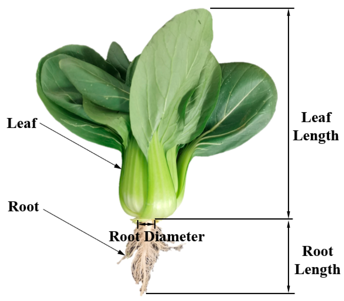
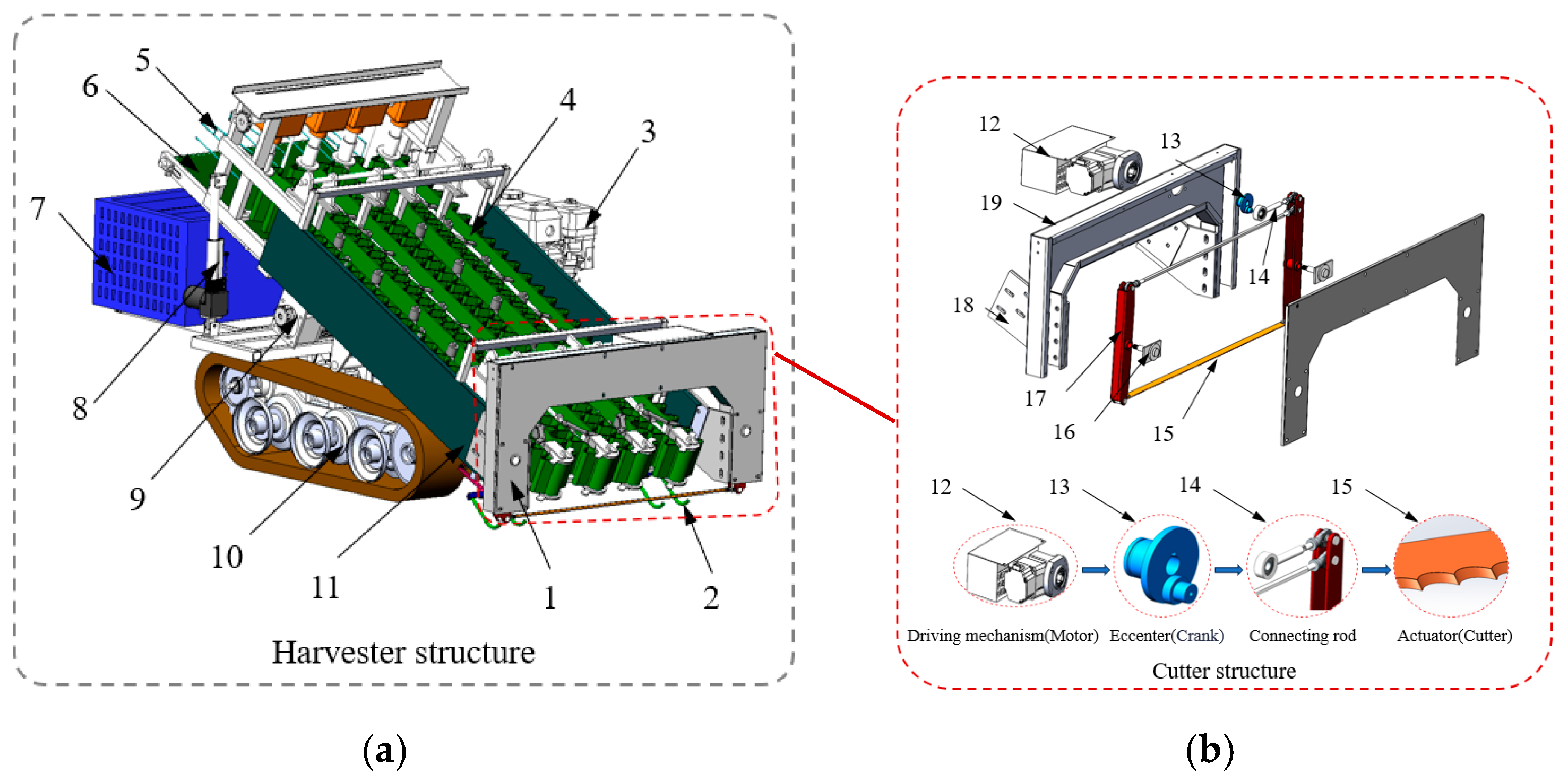
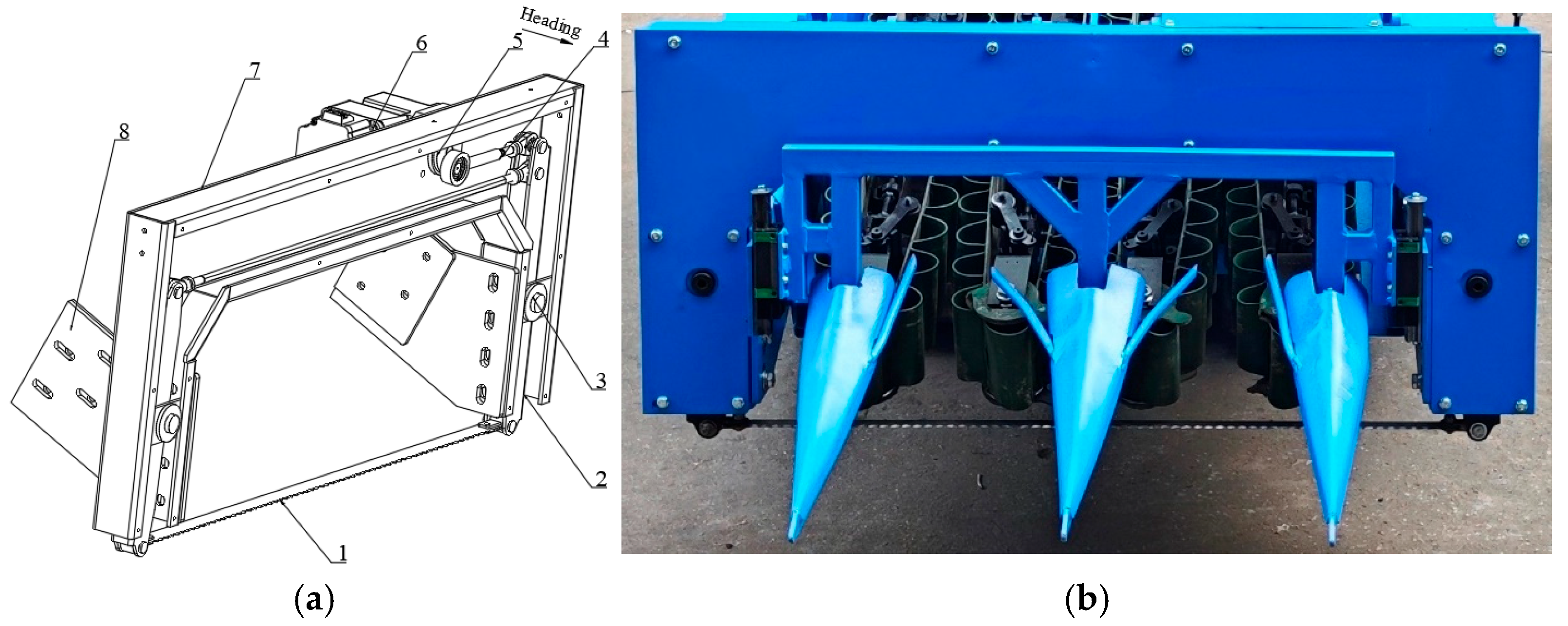
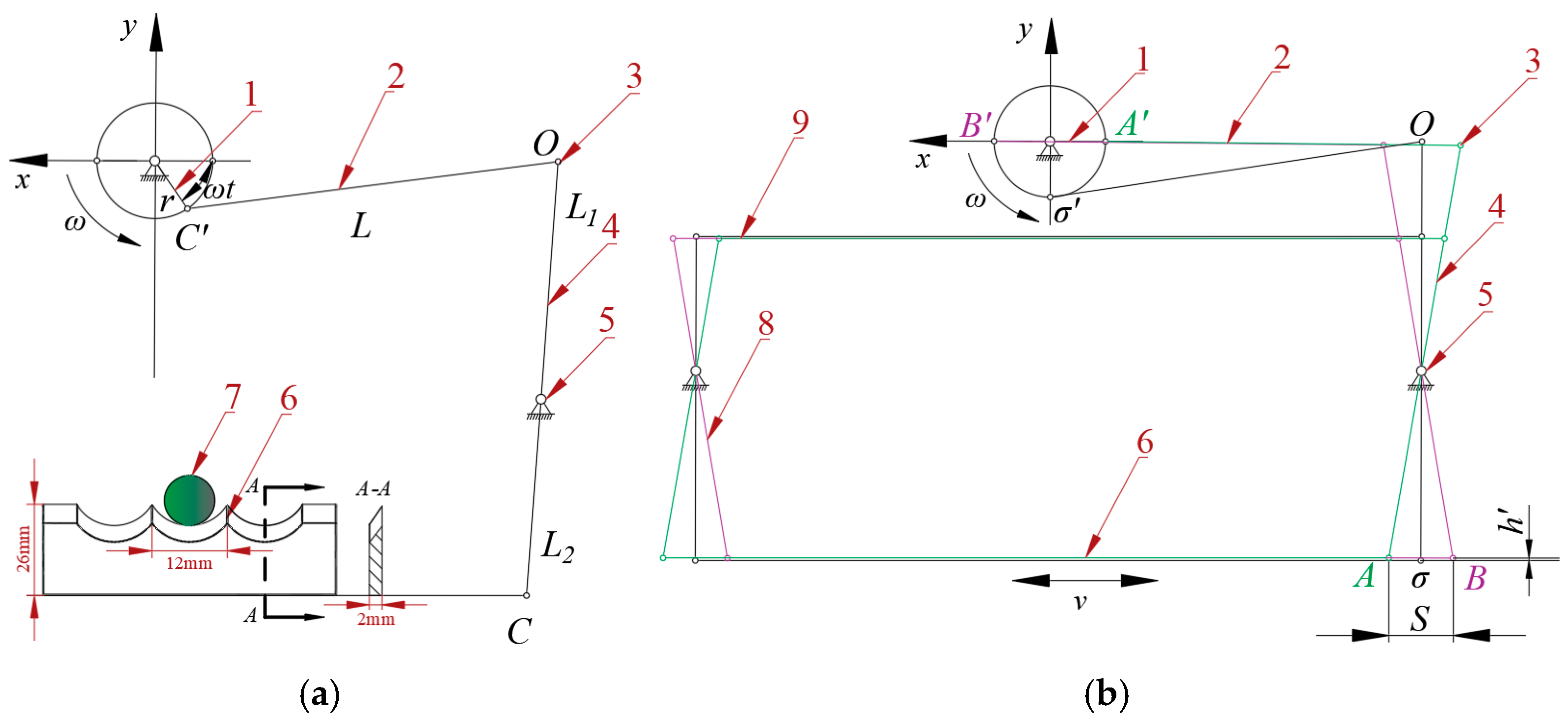

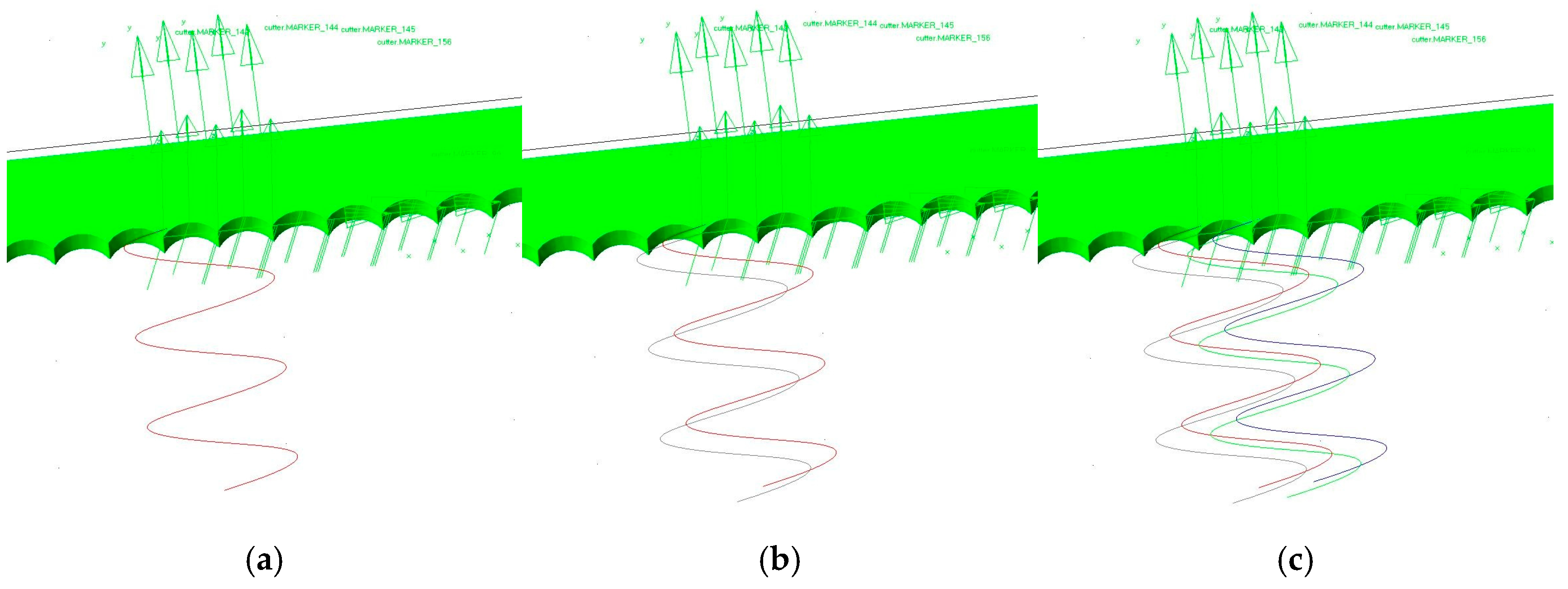
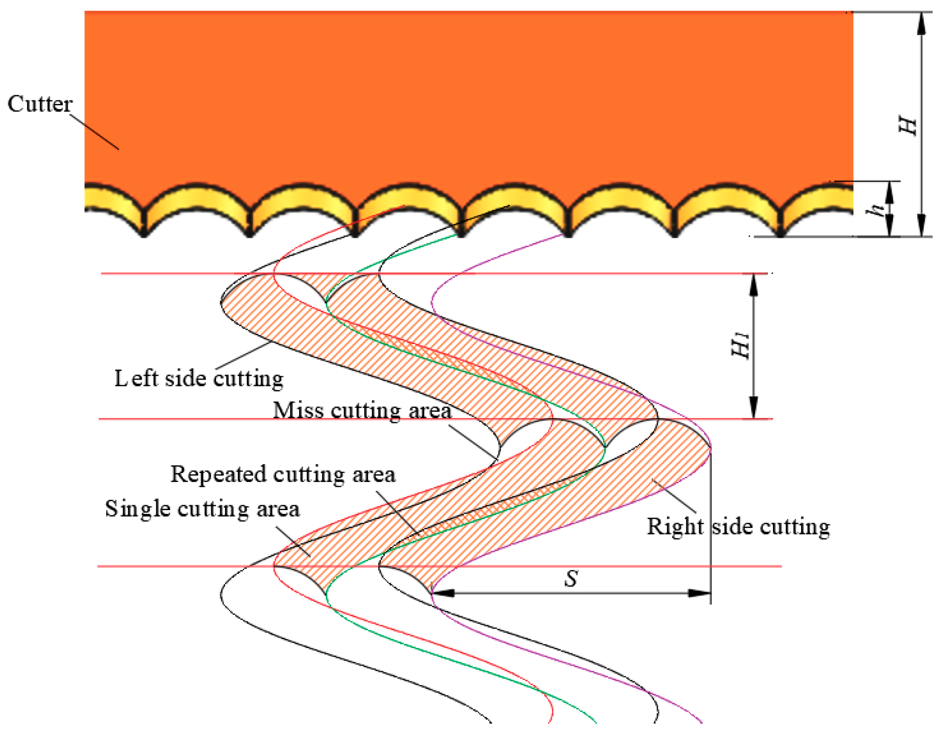

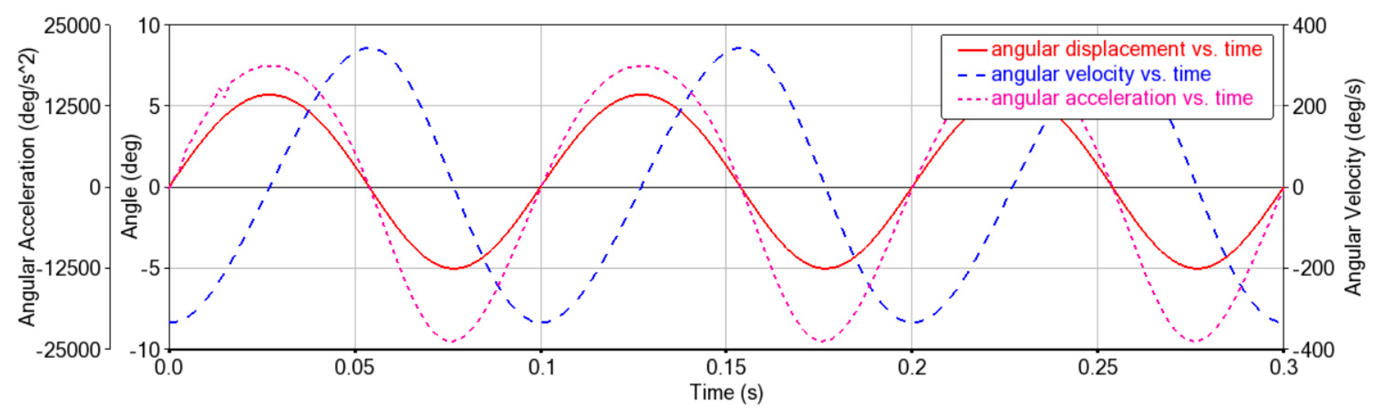
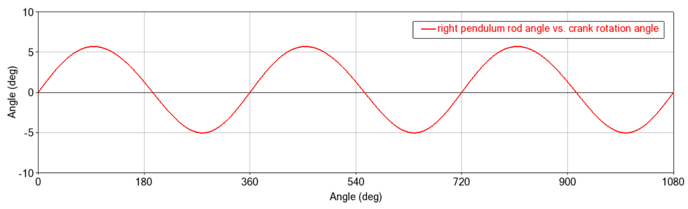

 ) Single-cutting area; (
 ) Repeated-cutting area; (
 ) Miss-cutting area).


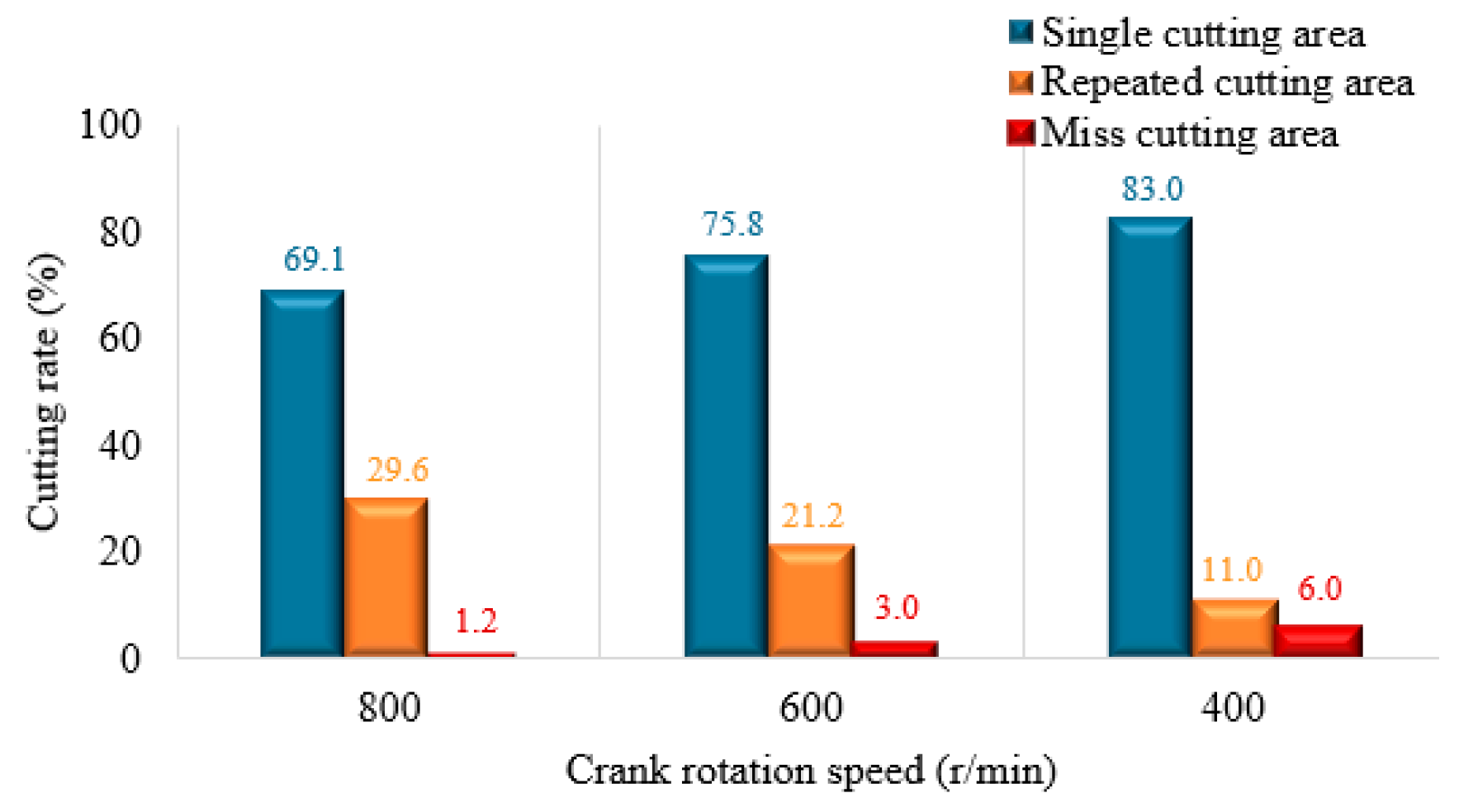
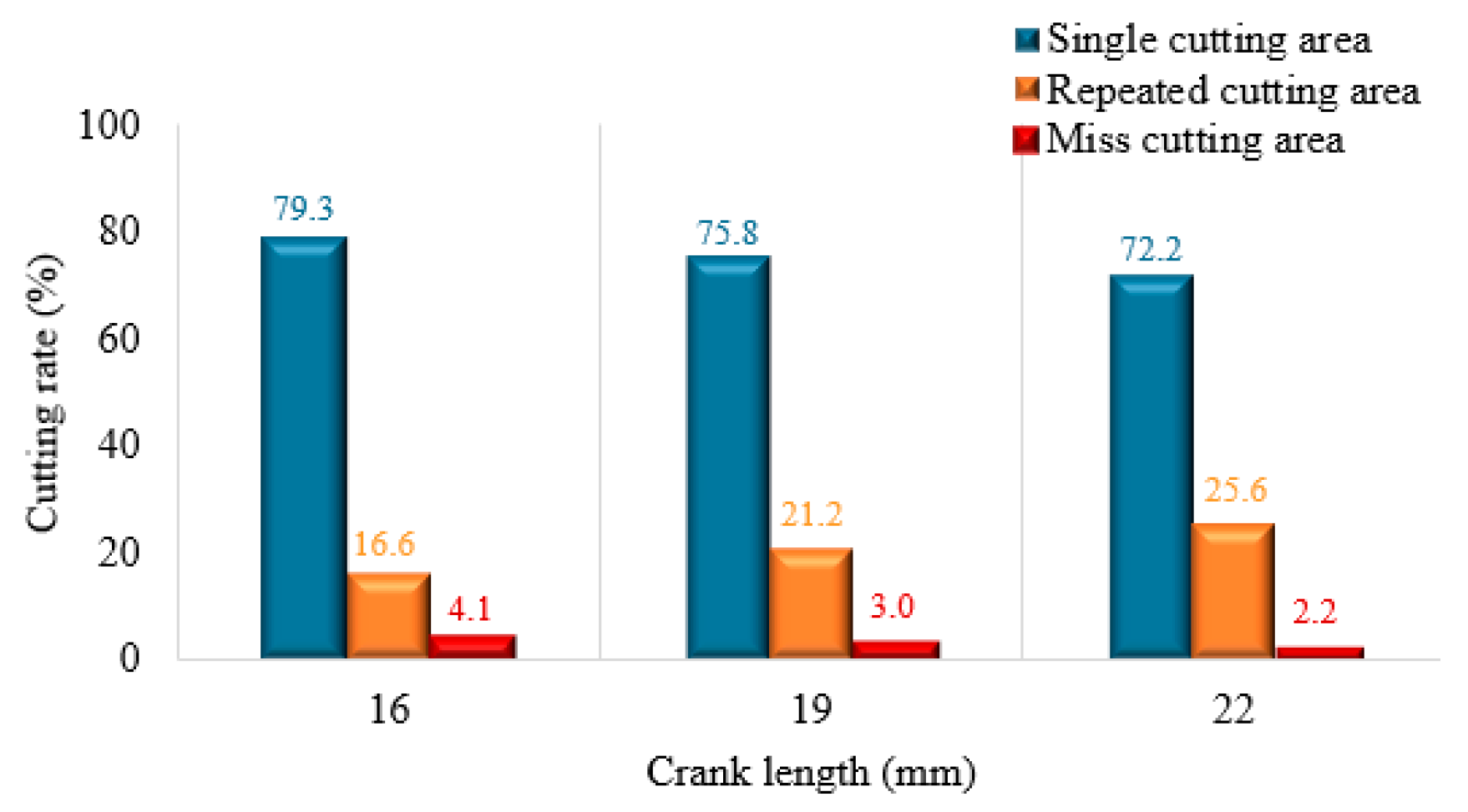
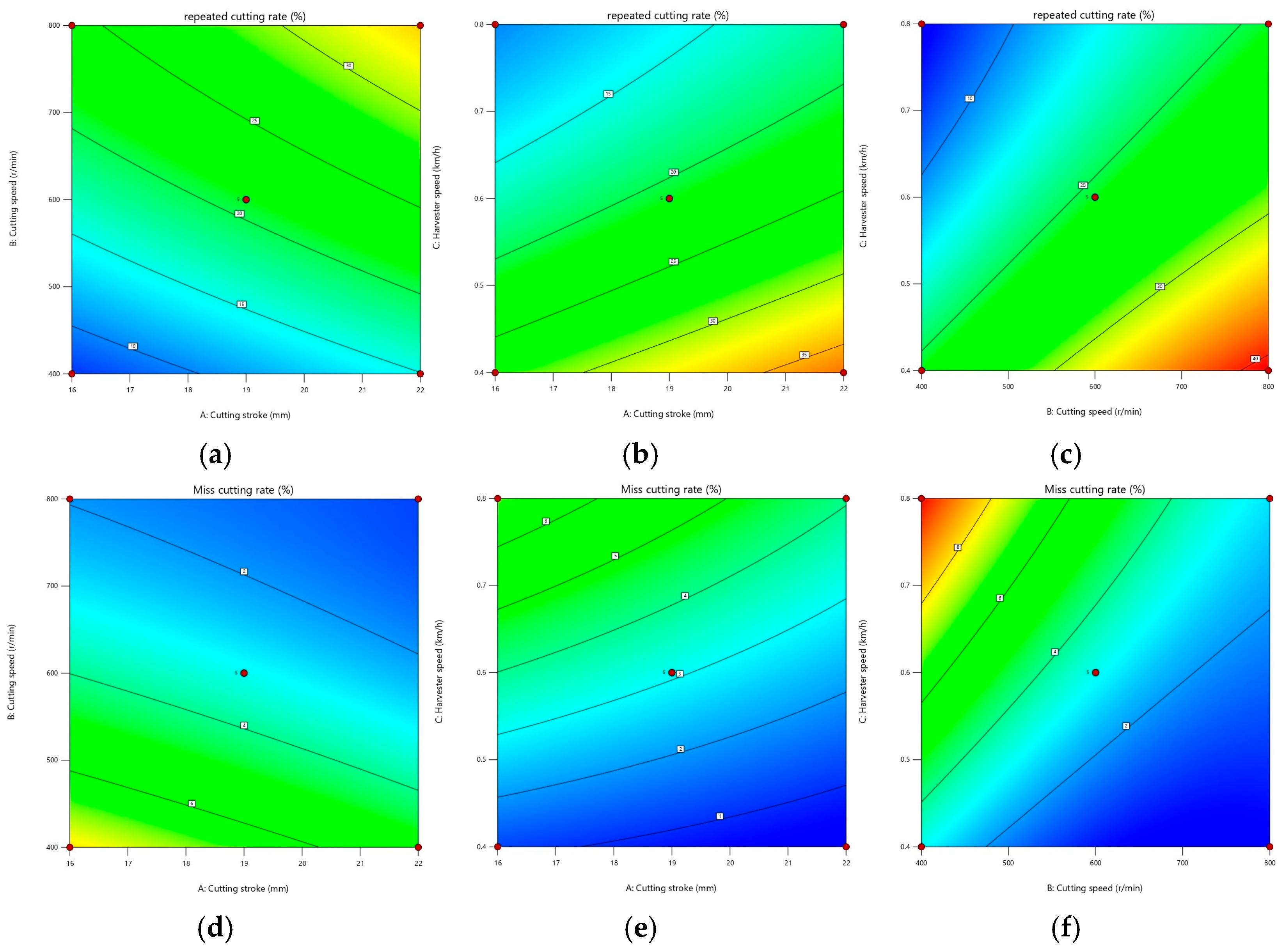
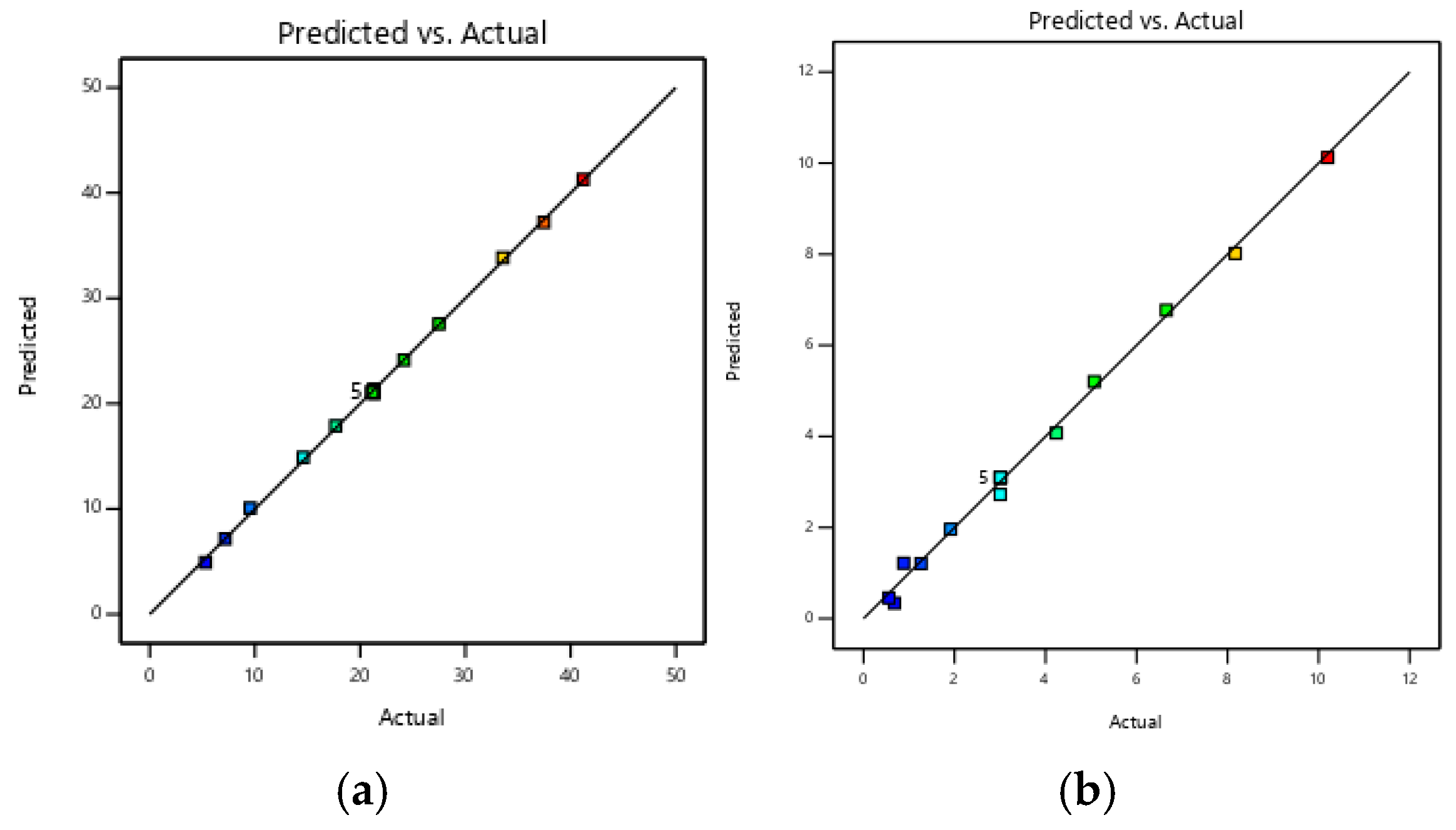
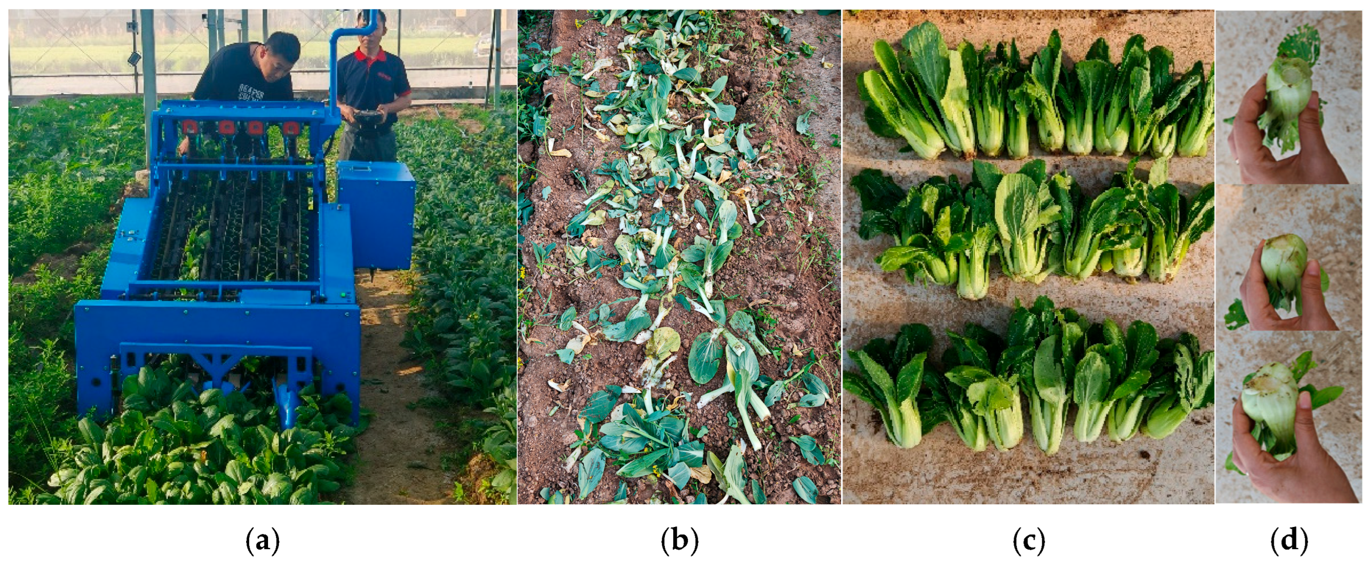
