Article

Four-Channel Emitting Laser Fuze Structure Based on 3D Particle Hybrid Collision Scattering Under Smoke Characteristic Variation

by
Zhe Guo
,
Bing Yang
and
Zhonghua Huang
*
School of Mechatronical Engineering, Beijing Institute of Technology, Beijing 100081, China
*
Author to whom correspondence should be addressed.
Appl. Sci. 2025, 15(13), 7292; https://doi.org/10.3390/app15137292
Submission received: 16 May 2025 / Revised: 19 June 2025 / Accepted: 27 June 2025 / Published: 28 June 2025

Abstract

Our work presents a laser fuze detector structure with a four-channel center-symmetrical emitting laser under the influence of the three-dimensional (3D) and spatial properties of smoke clouds, which was used to improve the laser fuze’s anti-smoke interference ability, as well as the target detection performance. A laser echo signal model under multiple frequency-modulated continuous-wave (FMCW) lasers was constructed by investigating the hybrid collision scattering process of photons and smoke particles. Using a virtual particle system implemented in Unity3D, the laser target characteristics were studied under the conditions of multiple smoke particle characteristic variations. The simulation results showed that false alarms in low-visibility and missed alarms in high-visibility smoke scenes could be effectively solved with four emitting lasers. With this structure of the laser fuze prototype, the smoke echo signal and the target echo signal could be separated, and the average amplitude growth rate of the target echo signal was improved. The conclusions are supported by the results of experiments. Therefore, this study not only reveals laser target properties for 3D and spatial properties of particles, but also provides design guidance and reasonable optimization of FMCW laser fuze multi-channel emission structures in combination with multi-particle collision types and target characteristics.

1. Introduction

As a professional control system that utilizes active laser detection technology to achieve precise detonation of a weapon’s explosives, the working performance of laser proximity fuzes is highly susceptible to the influence of aerosol particles in the atmosphere [1,2]. Combustion or chemical reactions produce a large number of small smoke particles, which rapidly diffuse and remain suspended for long periods of time, to form dense clouds of smoke in the working scene. Under low-altitude operating conditions, an actively emitting laser is subject to severe scattering effects and transmission energy attenuation [3,4]. The waveform distortion of the target echo results in the unsaturation of ground laser fuzes, which can cause false alarms, missed alarms, and extreme malfunctions [5].
In a dense smoke environment, frequency-modulated continuous-wave (FMCW) laser fuzes have a high anti-electromagnetic interference capability [6], which can use the beat signals to obtain frequency-domain characteristics and information such as target distance. In aerosol environments such as smoke, laser multipath transmission effects can cause waveform expansion of the laser echo signal [7]. Laser wavelength not only changes the amplitude of the echo signal, but laser multiple scattering is also affected by the change in wavelength [8,9]. In addition, the type of aerosol environment affects the amplitude of the laser backscattered echoes, and the waveform of the echo signal is also affected by aerosol-specific parameters [10,11]. Thus, negative impacts on this system can be caused by false alarms and false positive situations.
To improve laser fuze detection performance, the focus is to improve the anti-interference ability of laser fuzes for aerosols such as smoke [12]. In fact, the space volume, actual power consumption, and development costs of laser fuzes can be severely limited [13]. Under these conditions, target echo amplitude enhancement of the laser echo signal from the structure of the laser detector is a reasonable and effective approach [14]. For a smoke scene, designing and adopting multiple laser coherent emission fuze structures is an effective means of enhancing detection performance, which can equivalently increase the overall power of the emitting laser by setting up multiple lasers [15].
However, smoke contains microparticles and combustibles from the air, with particle sizes normally ranging from a few micrometers to tens of micrometers, where the dynamics of smoke particles are mainly characterized by diffusion and deposition [16]. Under conditions of constant-smoke visibility, it is necessary that there should be variability in the internal structure of the smoke environment, and the number of particles, particle size, and suspension locations are also variable and indeterminate. The scattering and transmission processes of photons colliding with smoke particles can be affected, which can lead to a reduction in the confidence in laser fuze target characteristics. In such cases, a multiplexed laser emitting structure will be more affected by the combined effects of the laser planar layout and the intersecting attitude of the laser detector with the ground target than by the individual lasers. The relative degree to which the emitted photons are spatially scattered with uncertainty by the smoke particles is greater, and the number of photons actually captured at the receiver of the laser detector is affected by the uncertainty, which reduces the effect of the amplitude enhancement of the echo signal under multiple emitted lasers.
The root cause of the above situations is the difficulty in reflecting the important influence of the spatial properties of smoke particles in laser transmission models. A constructed theoretical model only outputs light range and direction for the numerical results of a single smoke particle, which ignores the objective effect and correlation of the three-dimensional and spatial properties within the smoke cloud. A particle collision and transmission model is not characterized by a spatial structure factor and it is difficult to reasonably explain the situation regarding laser target properties. To solve this problem, it is necessary to construct a laser echo signal model based on the process and type of photon spatial transmission, and to output the target characteristics by simulating the laser target echo signal based on the variations in smoke environment characteristics. Thus, we studied the influence of smoke particle characteristics and their variability on the echo characteristics of a laser target, and verified the anti-smoke interference ability of a multi-channel laser emission structure, which provides a theoretical basis for the optimization of a continuous-wave laser emission system.
The remainder of this paper is organized as follows: Section 2 shows the scattering process under hybrid collision of photons and smoke particles. Section 3 models the laser echo power signal for a multi-channel continuous-wave laser and accurately outputs the target distance based on the beat signal and frequency. Section 4 reports the simulation and comparison of continuous-wave laser target characteristics, to study the influence of a change in smoke particle characteristics on the echo characteristics under a single channel, which was used for experimental validation of the multi-channel continuous-wave laser detection performance in Section 5. The conclusions are summarized in Section 6.

2. Three-Dimensional Collision and Transmission Processes of Photons in Smoke

The transmission process of an emitting laser in smoke can be described by the interaction between shaped hypothetical particles based on wave–particle duality, collisional dynamics, and the law of momentum conservation [17]. Laser fuzes employ lasers with wavelengths in the range of 0.65 μ m to 1.65 μ m, and the large number of small suspended particles in a smoke scenario have sizes ranging from a few micrometers to over a dozen micrometers, which is close to the size of these two types of particles [9]. Thus, the elastic scattering of photons by smoke particles adheres to the Mie scattering model [18], and the collision between photons and individual smoke particles can be approximated as a fully elastic collision based on spherical particles. Under this condition, the intersection detection results indicate whether the backward scattering process exists for small-sized photons collided by large-sized smoke particles based on the particle motion trajectories at adjacent time intervals.
Combined with the three-dimensional properties of particles, the specific process of backscattering depends on the probability of spatial collision between particles. In the case of photon incidence towards a single smoke particle, the particle collision probability can be determined from the maximum 3D collision cross-section between the particles, which is shown in Figure 1.
For a determined single smoke particle, the collision probability p c 1 is expressed as
p c 1 ( t 0 t 0 + Δ t ) = i = 1 N p h o t o n n p h o t o n N p h o t o n × π ( r s + r p ) 2 × Δ v i Δ t
where n p h o t o n and N p h o t o n are the number of particles emitted in a localized area and the total number of emissions, respectively. The bottom surface of the localized area is the maximum three-dimensional collision cross-section π ( r s + r p ) 2 and the height is light range. r p and r s are the size of the photon and smoke particle, respectively. Δ v is the relative movement speed of the particles. Δ t is the time interval and t 0 is the initial moment.
Low-visibility smoke scenes are characterized by a dense positional distribution of smoke particles in space, due to the inclusion of a large number of freely suspended smoke particles. When the center-of-mass distance of the smoke particles exceeds the sum of the radius of the two smoke particles and the diameter of the photon particle, an emission photon is simultaneously affected by the collision of multiple smoke particles. The collision cross-section of any two particles is shown in Figure 2.
Similarly to the case of a single smoke particle, the velocity vector of an emission photon is affected by a combination of the initial velocity distribution and the collision geometry. The former includes the velocity direction, magnitude, and relative position, while the latter is the contact position between the photon and multiple smoke particles. During multisphere elastic collisions with smooth particles, the velocity vector change is mainly expressed in the non-symmetric direction deflection, and the rotational motion of the particles can be neglected. Thus, the collision probability can be calculated by using the combined area of the collision cross-section.
Based on Figure 2, the collision cross-section σ s c can be expressed based on the intersecting circle equation, as shown:
σ s c = π ( r s 1 + r p ) 2 + π ( r s 2 + r p ) 2 1 2 θ 1 ( r s 1 + r p ) 2 1 2 θ 2 ( r s 2 + r p ) 2 1 2 ( r d + r s 1 + r s 1 ) ( r d + r s 1 r s 1 ) ( r d r s 1 + r s 1 ) ( r d + r s 1 + r s 1 )
where the first term is the sum of the single collision cross-section areas. r s 1 and r s 2 are the particle sizes of different spherical smoke particles, and θ 1 and θ 2 correspond to the maximum collision circumferential angles, respectively. The second and third terms are expressed as the area of the combined collision cross-section, which is related to the particle size, as well as the distance from the center of the sphere.
On this basis, the collision probability p c N of a photon with multiple smoke particles can be expressed as
p c N ( t 0 t 0 + Δ t ) = i = 1 N p h o t o n n p h o t o n N p h o t o n × σ s c ( r s 1 , r s 2 ) × Δ v i Δ t
Based on Equations (1) and (3), the photon collision probability depends on the 3D collision cross-section. The scattering direction of particles after a collision can only be determined if the collision probability is known. Otherwise, the direction of transmission always remains the same.
For the actual direction of particle transport under perfect elastic collision conditions, the constant vector sum of the system momentum before and after the collision is used, which is shown in Equation (4):
p p + p s 1 + p s 2 = p p + p s 1 + p s 2
where p p is the average momentum vector of a large number of emission particles, which are used to represent the laser beam before the collision. p s 1 and p s 2 are the momentum vectors of the two smoke particles. p p , p s 1 , and p s 2 are the momentum vectors after the collision, respectively.
When photons are incident on any two smoke particles, the simultaneous collision interaction that occurs instantaneously can be regarded as a two-body collision process within a brief time interval. As the photon movement speed is much higher than the velocity of the smoke particles, the collision process between these two particles is exceedingly short, which can be neglected for the collision process of particle deformation and internal structure alteration. Under these fast collision conditions, the particle can be considered to remain rigid before and after the collision. Moreover, the wavelength of the emitted laser is usually close to 1 μ m, which can ensure that the size of the photon particles is smaller than the size of the smoke particles. Thus, in the case of perfect elastic collisions based on the particles of a rigid sphere, the angle between p p and p p is expressed as the scattering angle θ s , which is shown in Figure 3. r r 1 and r r 2 are the radius of a rigid-body particle.
Depending on the relative spatial positions of the two smoke particles, the scattering direction of the scattered particles is determined by the angle θ v c between the center-of-mass line of the smoke particles and the direction of incident velocity. The particle scattering angle θ s can be expressed as
θ s = 2 θ v c , 0 < θ v c π 2 2 π 2 θ v c , π 2 < θ v c π
The collision angles θ p s 1 and θ p s 2 are the angles between the center-of-mass line at the contact position of the particle and the direction of the initial velocity, respectively. When θ p s 1 < θ p s 2 , the particle scattering angle θ s can be quantitatively expressed as
θ s = 7 2 π 4 θ p s 1 3 θ p s 2 , π 4 < θ p s 1 < π 2 5 2 π 4 θ p s 1 3 θ p s 2 , 0 < θ p s 1 < π 4 3 2 π 2 θ p s 2 , θ p s 1 = π 4
where the collision angles θ p s 1 and θ p s 2 can be expressed geometrically as
θ p s 1 = arcsin b p s 1 r r 1 + r p , θ p s 2 = arcsin b p s 2 r r 2 + r p
where the collision parameters b p s 1 and b p s 2 are the vertical distances between the direction of particle incidence and the centers of particles, respectively. A simultaneous collision situation only occurs if the conditions are maintained around b p s 1 < r r 1 + r p and b p s 2 < r r 2 + r p . Otherwise, the particle scattering angle θ s is only related to the collision angle θ p s of the colliding particles:
θ s = π 2 θ p s = π 2 arcsin b p s r r + r p
where b p s and r r are the collision parameters and smoke particle radius in the single particle condition, respectively. The results of Equation (8) compared to Equation (6) show the change in type of front-to-back scattering. In addition, increasing the scattering angle also increases the degree of backscattering until complete backscattering of particles appears, where the scattering angle is θ s = 2 π . Thus, the smoke echo signal will have a high amplitude and the subsequent target detection will be negatively affected by the lower signal-to-noise ratio (SNR) of the output echo signal.
In summary, the existence of spatial collision probabilities is an important precondition for collisional scattering of emitted particles. By determining the particle collision type and obtaining the particle collision angle, it is possible to output the direction of collision scattering of photons under a scene with many smoke particles. On this basis, the above findings provide the research basis for modeling laser echo signals under different photon transport collision types in Section 3.

3. Modeling of Laser Echo Signals Under Multi-Channel Continuous-Wave Lasers

To improve the target detection performance of the laser fuze, the amplitude of the target echo signal needs to be increased. The actual number of photons penetrating the smoke particle environment needs to increase, and the collision probability of the emission particles with the smoke particles needs to decrease. In low-visibility smoke environments, it is not meaningful to simply increase the total number N p h o t o n of particles emitted in the spatial collision probability from Equation (3), because the collision cross-section is objective. The particle collision angles θ p s 1 , θ p s 1 and θ p s are difficult to change, and this will not affect the subsequent direction of scattering transmission.
Before the transmission direction of the photons is changed, there is a possibility that the 3D collision cross-sections corresponding to different smoke particles overlap with each other, and the cross-section merging area is shown in Figure 4. Thus, it is reasonable to reduce the collision probability p c N by keeping the total number of emission particles N p h o t o n constant and decreasing the number of particles emitted n p h o t o n within the localization. We use simultaneous emission of particles into multiple initial spatial locations between the localized irradiation area of the laser source and the outside of the collision cross-section which corresponds to the multi-channel laser emission structure. When the number of optical paths is N L a s e r , the collision probability can be re-expressed as
p c N ( t 0 t 0 + Δ t ) = 1 N L a s e r × p c N ( t 0 t 0 + Δ t )
During laser fuze emission of laser light into a dense smoke environment, the photon energy can be expressed by the results of the change in weighting coefficients. Based on the smoke particle concentration and particle collision process, the photon transmission process is classified into photon collision with a single smoke particle, photon collision with any two smoke particles at the same time, and no collision. The initial weight is set to W 0 = 1 and the particle energy weight after collision can be expressed as
W N s c a = ( n s c a 1 = 0 n c 1 p c 1 ( s c a 1 ) × η s 1 ( s c a 1 ) ) × ( n s c a 2 = 0 n c 2 p c N ( s c a 2 ) × η s N ( s c a 2 ) ) × W 0
where n c 1 and n c 2 are the maximum number of collisions for the two different types. η s 1 and n s c a 1 are the energy attenuation coefficient and the number of collisions of photons with individual smoke particles. η s N and n s c a 2 are the energy attenuation coefficient and the number of simultaneous collisions of photons with multiple smoke particles, respectively.
Based on the Mie scattering model, it can be concluded that the laser intensity varies with the relative change in the scattering angle, which can be expressed by the scattering phase function as [19]. When the spatial distribution of smoke particles is uniform, the scattering phase function can be considered to only be related to the angle between the incidence and scattering. Based on the single scattering model [20], the echo power of a photon after collision with any two smoke particles can be expressed as
P δ ν i = P δ ν i 1 × Q s c a Ω T | d i | 2 × p ( θ p s 1 , θ p s 2 ) × e Q e x t × | d i | δ ν i
where δ ν is the sum of the unit volumes of multiple smoke particles corresponding to the collision scattering that occurs for photons. P δ ν i and P δ ν i 1 are the scattered power before and after the collision. Ω T is the stereo angle of the laser emission beam. Q s c a and Q e x t are the smoke scattering and attenuation coefficient. d is the photon shift vector. p ( θ p s 1 , θ p s 2 ) is the scattering phase function based on the collision angles of multiple particles. After the photons have been received, the laser echo power signal is expressed as
S c M ( t ) = ν 1 ν M P T A R η a t m η s y s Q s c a M cos φ r Ω T × i = 1 M p ( θ p s 1 , θ p s 2 ) | d i | 2 × e ( σ e x t × i = 1 M ) | d i | × δ ν i δ ν M × S T ( t τ M )
where P T is the laser emission power; A R is the laser receiving optical area; η a t m and η s y s are the atmospheric transmittance and the optical transmittance of the laser detection system, respectively; φ r is the angle between the received light and the axis of the received field of view; S T is the FMCW laser emission power signal; and τ M is the delay time under multiple collisions. In particular, when photons only collide with individual smoke particles, the scattering phase function p ( θ p s 1 , θ p s 2 ) also only needs to be expressed by the individual particle collision angle θ p s , and p ( θ p s 1 , θ p s 2 ) in Equation (12) can be transformed into θ p s .
On this basis, when a photon is received by the detector after collision with a stationary target at distance R, the laser target echo power signal under smoke conditions can be expressed as
S c N ( t ) = ν 1 ν M ν N P T A R η a t m η s y s Q s c a M ρ t cos φ r cos φ t Ω T × i = 1 M p ( θ p s 1 , θ p s 2 ) | d i | 2 × j = N M N p ( θ p s ) | d j | 2 × e ( σ e x t × ( i = 1 M | d i | + j = N M M | d j | ) ) × δ ν i δ ν M × S T ( t τ N )
where ρ t is target reflection coefficient; φ t is the incidence angle at which the photon collides with the target; τ N is the total delay time. When photons are not in collision with smoke particles and are received by the detector, or in a smoke-free environment, the laser target echo power signal can be expressed as
S c 0 ( t ) = P T × A R η a t m η s y s ρ t cos φ t R 2 e 2 σ e x t R × S T ( t τ T )
where the time delay is τ = 2 R c , and c is the speed of light.
For a multi-channel continuous-wave parallel laser emission system, as shown in Figure 5a, the collision probability is at this point directly affected not only by the number of particles emitted into the space in which they are located, but also by the spatial position of the emitted laser, as shown in Figure 5b, based on Equation (9).
The collision probability based on the emission of a multi-channel CW laser can be expressed as
p N L a s e r ( t 0 t 0 + Δ t ) = i = 1 N L a s e r j = 1 N p h o t o n n p h o t o n ( i j ) N p h o t o n × σ s c ( r s 1 , r s 2 ) × Δ v i j Δ t , N c 1 i = 1 N L a s e r j = 1 N p h o t o n n p h o t o n ( i j ) N p h o t o n × π ( r s + r p ) 2 × Δ v i j Δ t , N c = 1
where N c is the number of smoke particles when collisions occur with the emission particles. N c = 1 is the type of collision based on a single smoke particle, and N c 1 is the type of simultaneous collision of multiple smoke particles. n p h o t o n ( i j ) is the actual number of particles emitted in each channel in the space created by the light path and the collision cross-section, which is related to the beam divergence angle and positional layout of the emission laser.
Therefore, the photon collision probability is affected by the number of collisions, particle size, and relative spatial position of the smoke particles. Neglecting the relative time delay of the emitted laser in each channel, the laser received power signal based on the particle collision angles can be summarized as
S R ( t ) = i = 1 N L a s e r A m p i ( θ p s 1 , θ p s 2 , θ p s ) × P T S T ( t τ N i )
where A m p i ( θ p s 1 , θ p s 2 , θ p s ) is the amplitude coefficient of the laser received power signal. τ N i is the delay time corresponding to each laser.
Through the mixing of S T ( t ) and S R ( t ) signals to obtain the beat signal S B ( t ) , the frequency domain characteristics of the target detection echo signal and its pattern of variation can be extracted. On the basis of the triangular wave linear FM method, the instantaneous frequency f T ( t ) of the laser power signal S T ( t ) can be expressed as
f T ( t ) = f 0 2 B T m t + B 2 , t 0 , T m 2 f 0 + 2 B T m t + B 2 , t T m 2 , 0
where f 0 is the initial frequency; T m is the modulation period; and B is the sweep bandwidth. f T ( t ) is shown as a solid line in Figure 6.
Beat frequency f B ( t ) is expressed as
f B ( t ) = f R ( t ) f T ( t ) = 4 B T m t + 2 B T m τ , 0 t τ 2 4 B T m t 2 B T m τ , 0 t τ 2 2 B T m τ , τ t T m 2
where τ is the time delay of the laser echo signal compared to the emission signal, as shown by the red line in Figure 6.
For laser proximity fuzes, it can be concluded that τ T m and the beat frequency can be approximated as a constant. Thus, the relationship between the target distance R and beat frequency f B is summarized as
R = c T m 4 B f B
By extracting the frequency domain characteristics and variation patterns of the target echo signal and the smoke echo signal, the target characteristics of the laser fuze not only reflect the 3D and spatial attributes inside the smoke cloud, but also provide a basis for researching the effects of parameter variations on target characteristics in Section 4.

4. Simulation and Comparison of FMCW Laser Target Characteristics

4.1. Simulation Process of Single Laser Based on 3D Particle System

Based on the relationship between smoke concentration and visibility, it is reasonable to characterize smoke concentration through smoke visibility [21]. Under the condition of a constant smoke visibility, the concentration of smoke particles depends on the number, particle size, and spatial location of smoke particles in each localized volume of space. Variability exists in a smoke environment where the particles are uniformly distributed, and this will have different effects on the direction of the collision transmission of photons, as shown in Figure 7.
By comparing Figure 7a with Figure 7b, Figure 7c, and Figure 7d, respectively, the variability of the smoke environment can have an uncertain impact on the probability of collision between photons and smoke particles, due to changes in the number of collisions, particle size, and relative spatial positions of the smoke particles, which is specifically expressed as a change in the number of collisions occurring based on Equation (15). In this case, the type of collision angle is difficult to determine, while the other variables are also difficult to obtain directly, which is not useful for determining a specific expression for the laser echo power signal.
Since the collision angle is determined based on the interaction between three-dimensional particles, the simulation model also needs to be implemented in a three-dimensional virtual space. Unity3D is a highly integrated virtual reality platform that has a well-developed physics system and also includes a specialized particle system, in which the simulation models can be constructed [22,23]. Therefore, based on the long-term support version of Unity, such as 2017.4.40c1, it is possible to co-simulate the laser transceiver system and the smoke particle environment based on Monte-Carlo method. Using the output of the laser echo signal to obtain the fuze target characteristics, this method has been applied in the field of laser fuze target characteristic simulation and achieved good simulation results in our previous works [15,24].
Based on Equation (16), the specific form of the target echo power signal depends on the amplitude coefficient of the received power signal, which is related to the transmitting power amplitude, which is expressed in terms of the number of particles as
N p h o t o n ( t ) = P T S T ( t ) μ p
where μ p is the conversion factor. The laser emission power signal is transformed into a functional form based on the number of particles emitted:
S R ( t ) = i = 1 N L a s e r A m p i ( θ p s 1 , θ p s 2 , θ p s ) × μ p N p h o t o n ( t τ N i )
The particle system simulation can output a laser echo simulation signal, with the beat signal and its spectrum, and the simulation parameters are shown in Table 1 and the process is shown in Figure 8.
The beat frequency at a target distance of 3 m is expressed based on Equation (19) as
f B = 4 B c T m R = 4 × 150 MHz 3 × 10 8 m / s × 0.5 ms × 3 m = 12 kHz
Based on smoke particle concentration c s m o k e [21], the number of smoke particles generated can be adjusted as
n s m o k e = c s m o k e × η m o d = c t y p e × η m o d V γ t y p e
where c t y p e and y t y p e are constants, and their values are 37.3 and 1.07, respectively. η m o d is the coefficient for rounding the number of smoke particles.
Considering a large particle size distribution in a smoke environment, the influence of particle size on detection performance is of negligible practical significance [25]. The particle size of the smoke particles during the simulation can be set to the same value. Under this condition, by setting the laser wavelength to be less than 1 μ m, the size of photon particles is consistently smaller than that of smoke particles. The particle size ratio (PSR) is expressed as
P S R = L a s e r W a v e l e n g t h S m o k e P a r t i c l e S i z e
In the virtual environment of Unity3D, a low-visibility smoke scene was represented by setting up a large number of equal size and non-overlapping rigid-body particles. For the particle emission process under a single optical channel, the particle system simulation environments and processes corresponding to the three cases in Figure 7 are shown in Figure 9. To improve the simulation efficiency, it was necessary to increase the possibility of particle collision. In this case, the size of the smoke particles was taken as 1 μ m. Based on the laser wavelengths in Table 1, the PSR was approximated as 0.8. Under this condition, the target was set as an extended target and its area was assumed to be infinite.

4.2. Echo Characteristic Simulation Results Under Smoke Particle Characteristic Variation

Particle collision probability is affected by the number, particle size, and location of smoke particles, which directly results in a change of the particle collision scattering type. The amplitude of the smoke echo component and the target echo component of the laser echo signal will also be changed. Therefore, it is necessary to analyze the effect of variation in smoke particle characteristics on the echo characteristics of laser targets.
Under the condition of a single laser emission, the simulation results of the amplitude–frequency characteristics based on the beat signal spectra are shown in Figure 10, Figure 11 and Figure 12, respectively, based on the parameters in Table 1. The analysis is described as follows:
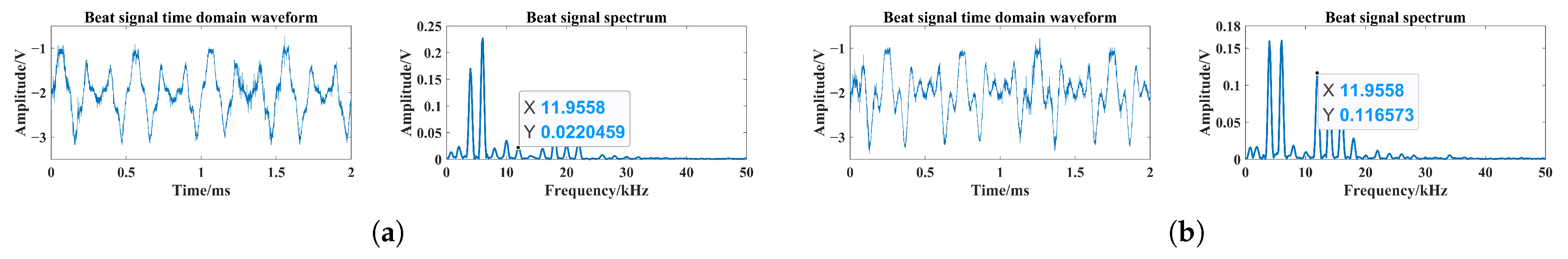
  • From Figure 10, the different numbers reduced the possibility of photon collision with smoke particles within the scene, and the laser penetration ability in the smoke changed locally, which had an impact on the echo characteristics. The percentage changes in the maximum peak frequency of the beat signal spectrum were 100% and 0, and the average value of the maximum peak frequency was 5 kHz and 12 kHz, respectively. Peak frequency migration and fluctuations occurred in the spectrum of the beat signal, as shown in the solid line area. In addition, frequency migration and fluctuations were affected by changes in visibility and only occurred in low-visibility smoke environments, even including the appearance of false alarms, such as the dotted line area in Figure 10a. For the high-visibility case, fluctuations in the amplitude of the maximum spectral peak occurred compared to the initial condition, as shown in Figure 10b.
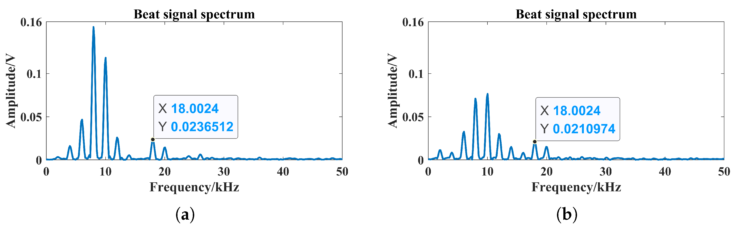
  • From Figure 11, the particle size difference increased the possibility of photon collision with smoke particles within the scene. At the same time, the laser penetration through the smoke was limited, and the laser echo characteristics were affected. The percentage of the maximum peak frequency of the beat signal spectrum changes were 89% and 100%, and the average value of the maximum peak frequency was 3 kHz and 8 kHz, respectively. Peak frequency migration and fluctuations occurred in the spectrum of the beat signal, which could lead to missed alarms in high visibility, as shown in the solid line area.
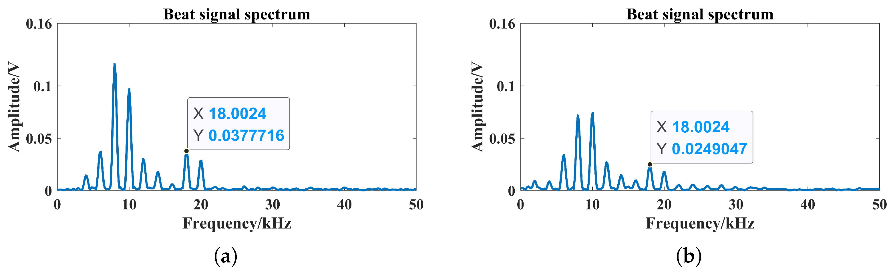
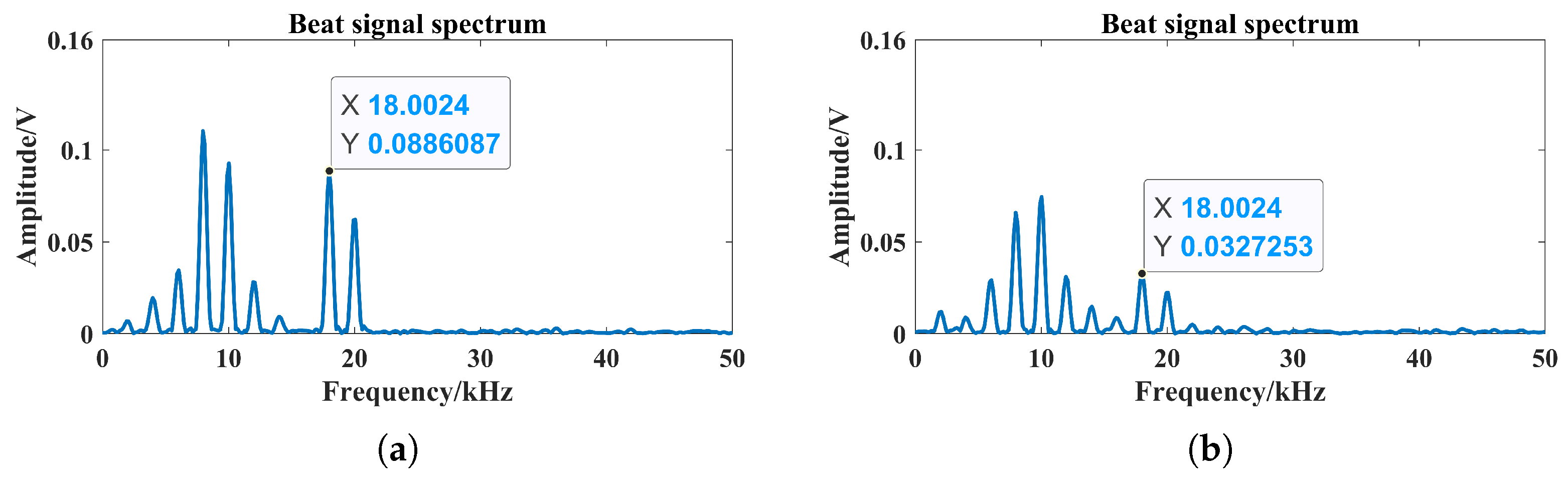
  • From Figure 12, the height differences affected the initial collision of photons with smoke particles within the scene. The ability of the laser to penetrate through the smoke was affected in an indeterminate way. Significant changes in the type of photon collision transmission occurred and the laser echo characteristics were more affected. In this case, the percentage changes in the maximum peak frequency of the beat signal spectrum were all 100%, and the average value of the maximum peak frequency was 8 kHz. Peak frequency migration and fluctuations occurred in the beat signal spectrum, as well as missed alarms in high visibility, as shown in the solid line area in Figure 12. Moreover, the lower the visibility, the larger the effect of the smoke particle position on the frequency migration and fluctuation.
In summary, the main effect of the beat signal spectrum peak fluctuation was the false and missed alarms caused by the difference in amplitude, which was analyzed here by comparing the initial amplitude with the average spectral amplitude under the action of each particle characteristic. The results of the amplitude comparison and average amplitude at each frequency are are shown in Figure 13.
From Figure 13, the positional difference had the largest effect on the peak amplitude of the laser echo signal under low-visibility conditions. The average growth rate in amplitude was about 75.4%. The number and particle size characteristics were about 16.2% and 20.6%, respectively. It is important to pay attention to the effects of changes in the number and location of smoke particles on the echo characteristics. Under high-visibility conditions, the effects of particle size and position changes on the peak amplitude of the laser echo signal were relatively greater. The average rates of change in amplitude were about 49.6% and 49.1%, while the number characteristic was only about 6.7%. Therefore, it is still necessary to focus on the effect of positional variations on the echo characteristics.
When the characteristics of the smoke particles were unchanged, the beat signal spectrum peak with a visibility of 15 m corresponded to a frequency of 12 kHz and it was the same as the beat frequency corresponding to the setting of a 3 m target, based on Figure 10, Figure 11 and Figure 12. However, the situation was the opposite at a visibility of 8 m, when the probability of collision was relatively larger. In this case, the type of collision at low visibility was dominated by the simultaneous collision of photons with multiple smoke particles, while at high visibility, the collision of photons with a single smoke particle was shown.
For a single-channel laser, false and missed alarms are affected by different smoke particle characteristics and their variations. The SNRs of a beat signal can be calculated using the ratio of the particle number in the target echo to the smoke echo, which can be expressed using the collision probability as
S N R L o w V i s b i l i t y = 10 l o g 10 1 p c N p c N = 10 l o g 10 n p h o t o n ( L o w ) N p h o t o n n p h o t o n ( L o w ) > 0 S N R H i g h V i s b i l i t y = 10 l o g 10 1 p c 1 p c 1 = 10 l o g 10 n p h o t o n ( H i g h ) N p h o t o n n p h o t o n ( H i g h ) < 0
where S N R L o w V i s b i l i t y and S N R H i g h V i s b i l i t y are the SNR for low and high visibility, respectively. p c N and p c 1 are the collision probability after a change in smoke particle characteristics, which can be expressed as
p c N = i = 1 N p h o t o n n p h o t o n N p h o t o n × σ s c ( r s 1 , , r s n ) × Δ v i j Δ t p c 1 = i = 1 N p h o t o n n p h o t o n N p h o t o n × π ( r s + r p ) × Δ v i j Δ t
The uncertainty in the collision probability, which was disturbed by variations in the number of photons emitted, caused significant errors in the SNR results and led to a failure to accurately detect the target. Therefore, it was necessary to increase the collision probability in low visibility and to decrease it in high visibility. On this basis, a reasonable layout of the multi-channel laser emission position is extremely important, which can enhance the anti-smoke interference ability of the laser detector.

5. Experiment

Multi-channel laser emission structures can equivalently increase the overall power of an emitted laser compared to a single-channel laser [15]. Based on the analysis in Figure 13, it was necessary to reduce the impact of the number and positional characteristics of the smoke particles. Therefore, multiple laser beams can be emitted in four directions within the laser irradiation area and outside the overlapping area of the three-dimensional collision cross-section. In this case, the number of optical channels can be changed from one to four, as shown in Figure 14.
At low visibilities, the collision probability ratio after the increase in the number of optical channels is expressed as
η l = p c N p c N = i = 1 N p h o t o n n p h o t o n N p h o t o n × σ s c ( r s 1 , r s 2 ) × Δ v i Δ t i = 1 N p h o t o n n p h o t o n N p h o t o n × σ s c ( r s 1 , , r s n ) × Δ v i j Δ t < 1
For high visibilities, the collision probability ratio after the increase in the number of optical channels is expressed as
η h = p c 1 p c 1 = i = 1 N p h o t o n n p h o t o n N p h o t o n × π ( r s + r p ) 2 × Δ v i Δ t i = 1 N p h o t o n n p h o t o n N p h o t o n × π ( r s + r p ) × Δ v i j Δ t > 1
From Equations (27) and (28), it can be seen that the multiple continuous-wave laser structure was able to deal with false and missed alarm situations. In this case, the structure could not only increase the probability of collisions in low visibility, but also reduce the probability of collisions in high visibility, which shows the structure has a better anti-smoke interference ability. Thus, the influence of variation in the smoke particle spatial position on the target echo signal was more significant, and the four-channel center-symmetric laser emission structure is a reasonable form. With the optical detector in the receiver as the center, the laser source can be set up symmetrically based on the central axis and the horizontal line, as shown in Figure 15.
As in Figure 10, Figure 11 and Figure 12, the particle emission process under multiple optical channels was simulated at the same time and the simulation results of the laser echo characteristics are shown in Figure 16, Figure 17 and Figure 18, respectively.
Comparing Figure 10 with Figure 16, Figure 11 with Figure 17, and Figure 12 with Figure 18, the false alarms in low visibility and missed alarms in high visibility were resolved. Thus, the increase in the number of optical channels improved the anti-smoke interference ability of the detector. The laser detector based on a four-channel center-symmetric emission structure is shown in Figure 19.
The laser transmitter module used four identical semiconductor lasers for simultaneous coherent emission and the delay between individual optical channels was no more than 5 ns, each with a wavelength of 0.808 μ m and a power of 500 mW. The divergence angle of the laser beams after collimation was no more than 5 degrees. The triangular wave linear FM signal used to modulate the laser intensity was swept with a bandwidth of 150 MHz and a period of 0.5 ms, the same as in Table 1. Photodetection reception utilized an avalanche photodiode (APD) with a wavelength response in the range of 0.4 μ m to 1.1 μ m, which is compatible with the reception of transmitting lasers. The distance between the laser and center position was kept the same based on Figure 14.
In the smoke condition, the laser beams were controlled to be vertically incident toward the target, and acquisition process of the laser beat signal is shown in Figure 20. The position between the target and the laser detector was set to 3 m. Comparison tests without and with the target were conducted to obtain the laser beat signal and its spectrum. The results for smoke visibility at 5 m, 8 m, 12 m, and 15 m are shown in Figure 21, Figure 22, Figure 23 and Figure 24.
By comparing the individual peak amplitudes close to the 12 kHz position, the smoke echo signal was completely separated from the target echo signal. The peak amplitude difference increased with increasing visibility, and the average value was 0.0836 V. Thus, the laser detector based on the four-channel center-symmetric emission structure had a better anti-smoke interference ability. The amplitude growth rate of the target echo signal based on the visibility of 5 m is shown in Table 2. With the increase in visibility, the average amplitude growth rate was 180.2%. The amplitude of the target echo signal was indeed enhanced.
To further reflect the detection performance of the four-channel emission laser structure, the target distance was moved to a more distant 4.5 m position for the test, which corresponds to a change in beat frequency of
f B = 4 B c T m R = 4 × 150 MHz 3 × 10 8 m / s × 0.5 ms × 4.5 m = 18 kHz
To evaluate the detection performance of the proposed structure, it is imperative to compare it with single-channel laser emission structure, which is currently the most widely adopted structure. For the same conditions of lower visibility, the beat signal spectrum under single and four-channel emission lasers is shown in Figure 25, Figure 26 and Figure 27. In this case, single-channel emission selected one of the four channels individually.
The individual peak amplitudes close to the 18 kHz position are labeled in Figure 27. Based on the results of Figure 25, the amplitude growth rates and ratios of the target echo signals are shown in Table 3. The SNR results are shown in Table 4.
Based on Table 3, with the increase in the number of optical channels, the overall power of the emission laser not only increased, but the ratio of the increase in the target echo signal amplitude also increased with the increase in visibility. Within the same range of visibility fluctuations as shown in Table 4, the SNRs of the beat signal spectrum were 36% and 88% for single and four channels, respectively. This implies a 147% enhancement in SNR resulting from the increase in the number of channels. The above conclusions clearly demonstrate the better target detection ability of the detector when employing this particular structure.

6. Conclusions

In this paper, based on a hybrid collision scattering process of photons and smoke particles, a fuze detector was designed for a four-channel center-symmetric emission laser structure, taking into account the three-dimensional and spatial properties of smoke clouds. By studying the collision probability and collision scattering angle when photons simultaneously collide with multiple smoke particles, a laser echo power signal model under multiple continuous-wave lasers was established. It is concluded that the collision transmission process was affected by the combined effects of the number of collisions, particle size, and the relative spatial positions of smoke particles.
Based on various photon 3D collision types, a virtual particle simulation model was developed using Unity3D, to output the laser echo power signal and extract the target characteristics. When the characteristics of the smoke particles were varied, the simulation results showed that the target characteristics were mainly manifested as the false alarms and missed alarms caused by the difference in the amplitude of the laser echo signal. In this case, it is crucial to mitigate the impact of the number and spatial distribution characteristics of smoke particles.
In the validation process of a four-channel center-symmetric emission laser structure, the simulation results showed that the false alarm rate in low visibility and the missed alarm in high visibility could be effectively mitigated. The experimental findings indicate that the smoke echo signal and the target echo signal were separated effectively, and the anti-smoke interference capability of the system was enhanced significantly. The average growth rate of the target echo signal amplitude was 180.2% when the visibility was increased from 5 m to 15 m. In addition, as the visibility of the smoke was increased, the ratio of the target echo signal amplitude increased rises. An improvement of 147% in the SNR was observed with an increase in the number of channels. This further underscores the superior target detection capability of the detector when employing this structure.
In summary, the above contents and conclusions provide accurate and specific guidance for the optimization of multi-optical channel laser emission systems, which can further improve the anti-smoke interference and target detection performance of FMCW laser fuzes.

Author Contributions

Conceptualization, Z.G. and Z.H.; Methodology, Z.G.; Writing—original draft preparation, Z.G. and B.Y.; Analysis and interpretation of data, Z.G.; Writing—review and editing, Z.G.; Supervision, Z.H.; Project administration, Z.G. All authors have read and agreed to the published version of the manuscript.

Funding

This research received no external funding.

Institutional Review Board Statement

Not applicable.

Informed Consent Statement

Not applicable.

Data Availability Statement

All data are contained within the article and further inquiries can be directed to the corresponding author upon reasonable request.

Conflicts of Interest

The authors declare no conflicts of interest.

References

  1. Arora, V. Proximity Fuzes Theory and Technology; Defence Science Centre: New Delhi, India, 2010. [Google Scholar]
  2. Zhao, H. Fundamentals and Methodology of Radio Fuze; National Defense Industry Press: Beijing, China, 2012. [Google Scholar]
  3. Xue, J.; Cao, Y.; Wu, Z.; Chen, J.; Li, Y.; Zhang, G.; Yang, K.; Gao, R. Multiple scattering and modeling of laser in fog. Chin. Phys. B 2021, 30, 064206. [Google Scholar] [CrossRef]
  4. Zheng, D.; Qu, T.; Hu, C.; Lu, S.; Li, Z.; Yang, G.; Yang, X.J. An adaptive continuous threshold wavelet denoising method for LiDAR echo signal. Nanotechnol. Precis. Eng. 2024, 8, 023006. [Google Scholar] [CrossRef]
  5. Zhang, W.; Li, Y.; Huang, Z.; Ma, C. Fog backscattering interference suppression algorithm for fmcw laser fuze based on normalized frequency spectrum threshold. Optik 2017, 131, 188–193. [Google Scholar] [CrossRef]
  6. Torun, R.; Bayer, M.M.; Zaman, I.U.; Boyraz, O. Multi-tone Modulated Continuous Wave Lidar. In Proceedings of the Conference on Photonic Instrumentation Engineering VI, San Francisco, CA, USA, 5–7 February 2019. [Google Scholar]
  7. Zhang, W.; Li, Y.; Huang, Z. Research on the characteristics of fog backscattering signals for frequency modulated continuous wave laser fuze. Optik 2016, 127, 9046–9055. [Google Scholar] [CrossRef]
  8. Wang, F.; Chen, H.; Yang, S.; Xu, L. Comparison of detection performance of near-, mid-, and far-infrared laser fuzes in clouds. Appl. Opt. 2018, 57, 8078–8086. [Google Scholar] [CrossRef]
  9. Liu, B.; Song, C.; Duan, Y. The characteristics simulation of FMCW laser backscattering signals. Opt. Rev. 2018, 25, 197–204. [Google Scholar] [CrossRef]
  10. Pang, Z.; Song, C.; Liu, B.; Wang, X.; Deng, M.; Su, H. Accurate Ranging of Dual Wavelength FMCW Laser Fuze Under Different Types of Aerosol Interference. IEEE Sens. J. 2022, 22, 18953–18960. [Google Scholar]
  11. Xu, C.; Zha, B.; Zhang, R.; Xia, J.R.; Zheng, Z.; Li, S.P. Echo characteristics of pulsed lasers in non-uniform smoke environments. Opt. Express 2024, 32, 24222–24241. [Google Scholar] [CrossRef]
  12. Li, L.; Li, Y.; Gao, C.; Tu, J. Characterization of the detecting laser of narrow pulse collimation system for targets in clouds and fog. Aero Weapon. 2021, 28, 106–109. (In Chinese) [Google Scholar]
  13. Zha, B.; Zheng, Z.; Li, H.; Chen, G.; Yuan, H. Laser fuze specific target recognition based on grey system theory. Optik 2021, 247, 168020. [Google Scholar] [CrossRef]
  14. Li, J.; Lu, Y.; Yang, H.; Li, Z.; Liu, J.; Qiang, J.; Chen, Y. Detection of Atmospheric Wind Speed by Lidar Based on Quadrichannel Mach-Zehnder Interferometer. Photonics 2023, 10, 726. [Google Scholar] [CrossRef]
  15. Guo, Z.; Yang, B.; Wu, K.; Liang, Y.; Hao, S.; Huang, Z. FMCW Laser Fuze Structure with Multi-Channel Beam Based on 3D Particle Collision Scattering Model under Smoke Interference. Sensors 2024, 24, 5395. [Google Scholar] [CrossRef]
  16. Li, X.; Ma, Y.; Wang, Y.; Liu, N.; Hong, Y. Temporal and spatial analyses of particulate matter (PM10 and PM2.5) and its relationship with meteorological parameters over an urban city in northeast China. Atmos. Res. 2017, 198, 185–193. [Google Scholar] [CrossRef]
  17. Xie, L.; Zhong, H.; Du, Z.; Zhou, J. Monte Carlo simulation of electromagnetic wave transmittance in charged sand/dust storms. J. Quant. Spectrosc. Radiat. Transf. 2020, 241, 106744. [Google Scholar] [CrossRef]
  18. Al Naboulsi, M.; Sizun, H.; de Fornel, F. Fog attenuation prediction for optical and infrared waves. Opt. Eng. 2004, 43, 319–329. [Google Scholar] [CrossRef]
  19. Aptowicz, K.; Pan, Y.; Martin, S.; Fernandez, E.; Chang, R.; Pinnick, R. Decomposition of atmospheric aerosol phase function by particle size and asphericity from measurements of single particle optical scattering patterns. J. Quant. Spectrosc. Radiat. Transf. 2013, 131, 13–23. [Google Scholar] [CrossRef]
  20. Elshimy, M.A.; Hranilovic, S. Non-line-of-sight single-scatter propagation model for noncoplanar geometries. J. Opt. Soc. Am. A-Opt. Image Sci. Vis. 2011, 28, 420–428. [Google Scholar] [CrossRef]
  21. Ryde, J.; Hillier, N. Performance of laser and radar ranging devices in adverse environmental conditions. J. Field Robot. 2009, 26, 712–727. [Google Scholar] [CrossRef]
  22. Rassolkin, A.; Rjabtsikov, V.; Kuts, V.; Vaimann, T.; Kallaste, A.; Asad, B.; Partyshev, A. Digital Twin of an Electrical Motor Based on Empirical Performance Model. IEEE Access 2022, 10, 15635–15643. [Google Scholar] [CrossRef]
  23. Li, G.; Zhang, J.; Yang, J. Ocean Simulation Based on Particle System. In Proceedings of the 5th International Conference on Environmental Science and Material Application (ESMA), Xian, China, 15–16 December 2019. [Google Scholar]
  24. Guo, Z.; Yang, B.; Liang, Y.; Huang, Z. Virtual Simulation of the Effect of FMCW Laser Fuse Detector’s Component Performance Variability on Target Echo Characteristics under Smoke Interference. Materials 2022, 15, 4268. [Google Scholar] [CrossRef]
  25. Wang, F.; Chen, H.; Ma, C.; Xu, L. Construction of backscattering echo caused by cloud in laser fuze. Optik 2018, 171, 153–160. [Google Scholar] [CrossRef]
Figure 1. Three-dimensional collision cross-section between a photon and a single smoke particle.
Applsci 15 07292 g001
Figure 2. Three-dimensional collision cross-section between a photon and any two smoke particles.
Applsci 15 07292 g002
Figure 3. Scattering angle and collision angle based on rigid-body sphere collision.
Applsci 15 07292 g003
Figure 4. Overlapping areas of 3D collision cross-section for the collision of two smoke particles.
Applsci 15 07292 g004
Figure 5. Multi-channel parallel laser coherent emission systems and target detection processes: (a) smoke-filled scene, (b) smoke-free scene.
Applsci 15 07292 g005
Figure 6. Transmission frequency, receiving frequency, and beat frequency based on triangular wave linear FM.
Applsci 15 07292 g006
Figure 7. Effects of changes in the number of smoke particles, particle size, and spatial location on the photon transmission process: (a) initial situation, (b) changes in the number of smoke particles, (c) changes in the particle size, (d) changes in the spatial location of smoke particles.
Applsci 15 07292 g007
Figure 8. Simulation process of FMCW laser beat signal based on 3D particle collision types.
Applsci 15 07292 g008
Figure 9. Setup and process of laser prototype test and virtual particle system simulation: (a) Smoke particle count reduction, (b) smoke particle size enlargement, (c) smoke particle position downshift.
Applsci 15 07292 g009
Figure 10. Amplitude–frequency characteristics of the beat signal spectrum for smoke particle count reduction: (a) Amplitude–frequency characteristics for a visibility of 8 m, (b) amplitude–frequency characteristics for a visibility of 15 m.
Applsci 15 07292 g010
Figure 11. Amplitude–frequency characteristics of the beat signal spectrum for smoke particle size enlargement: (a) Amplitude–frequency characteristics for a visibility of 8 m, (b) amplitude–frequency characteristics for a visibility of 15 m.
Applsci 15 07292 g011
Figure 12. Amplitude–frequency characteristics of the beat signal spectrum for smoke particle positional downshift: (a) Amplitude–frequency characteristics for a visibility of 8 m, (b) amplitude–frequency characteristics for a visibility of 15 m.
Applsci 15 07292 g012
Figure 13. Comparison of average results of beat signal spectral amplitudes in the case of amplitude variability.
Applsci 15 07292 g013
Figure 14. Position of four-emitter laser transmission based on overlapping areas of three-dimensional collision cross-sections.
Applsci 15 07292 g014
Figure 15. Four-channel laser emission structure based on center-symmetry of the receiving position.
Applsci 15 07292 g015
Figure 16. Amplitude–frequency characteristics of the beat signal spectrum for smoke particle count reduction based on four-channel emission lasers: (a) Amplitude–frequency characteristics for a visibility of 8 m, (b) amplitude–frequency characteristics for a visibility of 15 m.
Applsci 15 07292 g016
Figure 17. Amplitude–frequency characteristics of the beat signal spectrum for smoke particle size enlargement based on four-channel emission lasers: (a) Amplitude–frequency characteristics for a visibility of 8 m, (b) amplitude–frequency characteristics for a visibility of 15 m.
Applsci 15 07292 g017
Figure 18. Amplitude–frequency characteristics of the beat signal spectrum for smoke particle positional downshift based on four-channel emission lasers: (a) Amplitude–frequency characteristics for a visibility of 8 m, (b) amplitude–frequency characteristics for a visibility of 15 m.
Applsci 15 07292 g018
Figure 19. Laser detector based on a four-channel centro-symmetric emission structure.
Applsci 15 07292 g019
Figure 20. Schematic diagram of the acquisition process for laser beat signals.
Applsci 15 07292 g020
Figure 21. Laser beat signals and their spectra at smoke visibility of 5 m: (a) The target was not set in the smoke scene, (b) the target was set in the smoke scene.
Applsci 15 07292 g021
Figure 22. Laser beat signals and their spectra at a smoke visibility of 8 m: (a) The target was not set in the smoke scene, (b) the target was set in the smoke scene.
Applsci 15 07292 g022
Figure 23. Laser beat signals and their spectra at a smoke visibility of 12 m: (a) The target was not set in the smoke scene, (b) the target was set in the smoke scene.
Applsci 15 07292 g023
Figure 24. Laser beat signals and their spectra at a smoke visibility of 15 m: (a) The target was not set in the smoke scene, (b) the target was set in the smoke scene.
Applsci 15 07292 g024
Figure 25. Laser beat signals and their spectra at a smoke visibility of 4.8 m: (a) Four-channel emission laser, (b) single-channel emission laser.
Applsci 15 07292 g025
Figure 26. Laser beat signals and their spectra at smoke visibility of 5.7 m: (a) Four-channel emission laser, (b) single-channel emission laser.
Applsci 15 07292 g026
Figure 27. Laser beat signals and their spectra at smoke visibility of 6.2 m: (a) Four-channel emission laser, (b) single-channel emission laser.
Applsci 15 07292 g027
Table 1. Main parameters of the laser simulation in smoke.
ParameterValue
Laser wavelength0.808 μ m
Sweep bandwidth150 MHz
Modulation period0.5 ms
Emission divergence angle5 mrad
Receiving radius of lens6 mm
Receiving field of view45°
Target distance3 m
Target reflectivity0.3
Smoke visibility8 m, 15 m
Smoke particle count reduction range 0 , 0.45 n s m o k e
Smoke particle size enlargement range 0 , 0.9 r s
Smoke particle position downshift range 0 , 0.9 r s
Table 2. Amplitude growth rate of target echo signals based on visibility of 5 m.
Smoke Visibility8 m12 m15 mAverage
Amplitude growth rate74.2%171.7%294.6%180.2%
Table 3. Amplitude growth rate and ratio of target echo signals based on visibility of 4.8 m.
Smoke VisibilityFour-Channel Emission LaserSingle-Channel Emission LaserRatio
5.7 m18.1%55.1%3.04
6.2 m59.7%274.6%4.60
Table 4. The results of signal-to-noise ratio for visibilities of 4.8 m, 5.7 m, and 6.2 m.
Smoke Visibility4.8 m5.7 m6.2 m
Single-channel emission laser−5.59 dB−4.74 dB−3.57 dB
Four-channel emission laser−8.13 dB−5.06 dB−0.96 dB
Disclaimer/Publisher’s Note: The statements, opinions and data contained in all publications are solely those of the individual author(s) and contributor(s) and not of MDPI and/or the editor(s). MDPI and/or the editor(s) disclaim responsibility for any injury to people or property resulting from any ideas, methods, instructions or products referred to in the content.

