Abstract
The operating environment of perforated strings is highly complex, making their safety a critical concern, particularly when evaluating their performance under shock loading conditions. A simplified model of the perforated string system subjected to shock loading is developed, leading to the formulation of a shock load calculation model. This model is then used to analyze the relationship between peak pressure and axial force under shock loading. Based on field data and commercial software to verify the accuracy of the model, two wells in the Southwest region were evaluated for safety. The results show that, using this model, the peak pipe pressures under shock loading for the two wells are calculated to be 69.52 MPa and 82.93 MPa, respectively. When compared to results from a commercial software for analyzing wellbore dynamics, the error is minimal, suggesting that the model provides accurate calculations and predictions of peak pipe pressure within acceptable error margins. This model meets engineering requirements and can serve as a practical tool for safety evaluation. Overall, the findings demonstrate that the safety evaluation method and calculation model offer valuable guidance for engineering practice and provide a reliable reference for assessing the safety of perforated strings under shock loading conditions.
1. Introduction
With the continuous exploration and development of oil and gas resources, deep development has become the primary focus of oil and gas exploration. However, the operating environment for perforated string remains harsh, and the stress and deformation of the perforated string are complex. High-density shock loads with significant power generate large shock waves, which exert substantial forces on the perforated string, posing serious threats to the safety and reliability of the perforated string system [1,2,3,4,5].
Finite element analysis software was employed to simulate the effect of effective stress on perforated string under shock loading, considering factors such as perforated string length, wall thickness, and distance from the restraining end. Countermeasures were proposed to mitigate the impact effects [6]. A software model was utilized to predict transient pressure waves and structural loads on oil and gas well components, assessing the sensitivity of shock load effects on the design parameters of the perforated string system [7]. A dynamic load testing system was used to conduct pressure and acceleration tests on a perforated string, identifying the dynamic response characteristics of the perforated string [8]. Finite element analysis software was applied to examine the transient response stress intensity of the perforated string, with the results indicating that the maximum equivalent force in the thick-walled injection perforated string was small, thus suggesting high safety for the perforated string [9]. The finite element transient dynamic response method was employed to analyze the dynamic displacement, velocity, acceleration and equivalent force of the perforated string, exploring the relationships between ammunition density, charge, length and perforated string strength under shock loading [10]. A vibration mechanics model for the shot hole perforated string was established, and the relationship between intrinsic frequency, vibration type and displacement was analyzed. The dynamic response characteristics were obtained by applying a finite element model with measured loads [11]. Numerical simulations were conducted to examine the intrinsic relationships between various factors and the dynamic response of the perforated string, leading to the derivation and verification of a peak stress prediction model based on engineering parameters [12]. A three-dimensional impact dynamics model for the perforated string was developed, analyzing its dynamics based on field data and conducting a safety assessment [13]. A nonlinear dynamics model for horizontal wells was proposed to analyze the effect of high-temperature and high-pressure injection loads on vibration in ultra-deep wells [14]. The 3D finite element model of a perforated pipe string was established to reveal the dynamic mechanical behavior, weak points and key positions of perforated pipe string, and to study the response law of pipe string under different working conditions [15].
Existing methods often involve high computational costs and limited adaptability to local engineering scenarios and are mainly focused on isolated dynamic factors. In order to solve these limitations, a simplified finite element model is established in this paper. On the basis of theoretical analysis and numerical simulation, the safety of perforated pipe string under impact load is systematically studied, the influence of key factors is quantified, and the change law of peak pressure and axial force of perforated pipe string under impact load is studied. The feasibility and scientific validity of the model are verified by the safety check and calculation of the example well.
2. Analysis Model of Perforated String
With the increasing complexity of the operating environment for perforated strings and the escalating shock loads, safety issues related to perforated strings in test or construction sites have become increasingly prominent. Enhancing operational safety and mitigating the damage caused by shock loads on pipe strings have become critical objectives. The dynamic pressure generated in the wellbore of oil and gas wells at the moment of detonation constitutes the shock load. Intense shock loads are prone to cause damage and destruction to downhole tools during propagation, with the core of the impact process being the propagation of stress waves through the medium. The propagation of stress waves in the perforated string induces vibrations, and the continuous forward movement of disturbances within the perforated string represents the transfer of energy. Explosive detonation immediately produces high-temperature and high-pressure materials with immense energy, violently compressing the space around the explosion, which subsequently affects fluid motion behavior. Certain fluid parameters experience sudden changes, forming fluid shock waves, which are high-temperature, high-pressure wave fronts advancing at extremely high speeds. The mechanical analysis of a perforated string under shock loading involves multiple disciplines, including pressure wave propagation theory, shock dynamics theory, pipe string mechanics theory, fluid mechanics theory, rock mechanics theory, safety technology theory and finite element analysis. This presents a relatively complex research field [16,17,18,19,20,21,22].
The response of perforated string to shock loads is a complex nonlinear dynamic problem, involving the interaction of various dynamic loads. Theoretical analytical solutions are challenging to apply to such problems, and their analysis has significant limitations. Using experimental methods to study these problems incurs high costs and greater risks. Finite element simulation offers a practical solution to overcome the limitations of both theoretical and experimental approaches, providing strong operability.
2.1. Material Parameters
To ensure the reliability and accuracy of the finite element simulation results, material parameters are defined according to an appropriate Equation of state model. The key material model parameters in this simulation include explosive properties, air properties, injection fluid characteristics and stratigraphic parameters, among others.
(1) Explosives parameters (JWL Equation of state [23]).
where P1 is the blast pressure; V1 is the unit volume of explosive blast product volume; A1, A2, R1, R2 and ω are the Equations of state constants; E1 is the unit volume of explosive internal energy.
(2) Air parameters (LINEAR_POLYNOMIAL Equation of state [24]).
where C0–C6 are the Equation of state coefficients; C0, air, C1, air, C2, air, C3, air, C4, air, C5, air and C6, air are 0, 0, 0, 0, 0, 0.4, 0.4 and 0; μd is the density ratio, and the density of air is 0.001225 g/cm3.
(3) Injection fluid parameters (Gruneisen Equation of state [25]).
where ρm is the initial density of the surrounding medium; Cm is the intercept of the stress wave velocity curve; αm is the compression coefficient of the surrounding medium; γ0 is the coefficient of the Equation of state, taken as 0.35; δ is the correction amount; S1, S2 and S3 are the slope coefficients of the stress wave velocity curve.
(4) Stratigraphic parameters (Holmquist–Johnson–Cook model [26]).
where fc is the uniaxial compressive strength; q1, q2 and q3 are material parameters; P*N is a standardized pressure value; q4 is a formation damage value; and ε * is a standardized strain rate.
2.2. Simplified Analysis of Perforated String System
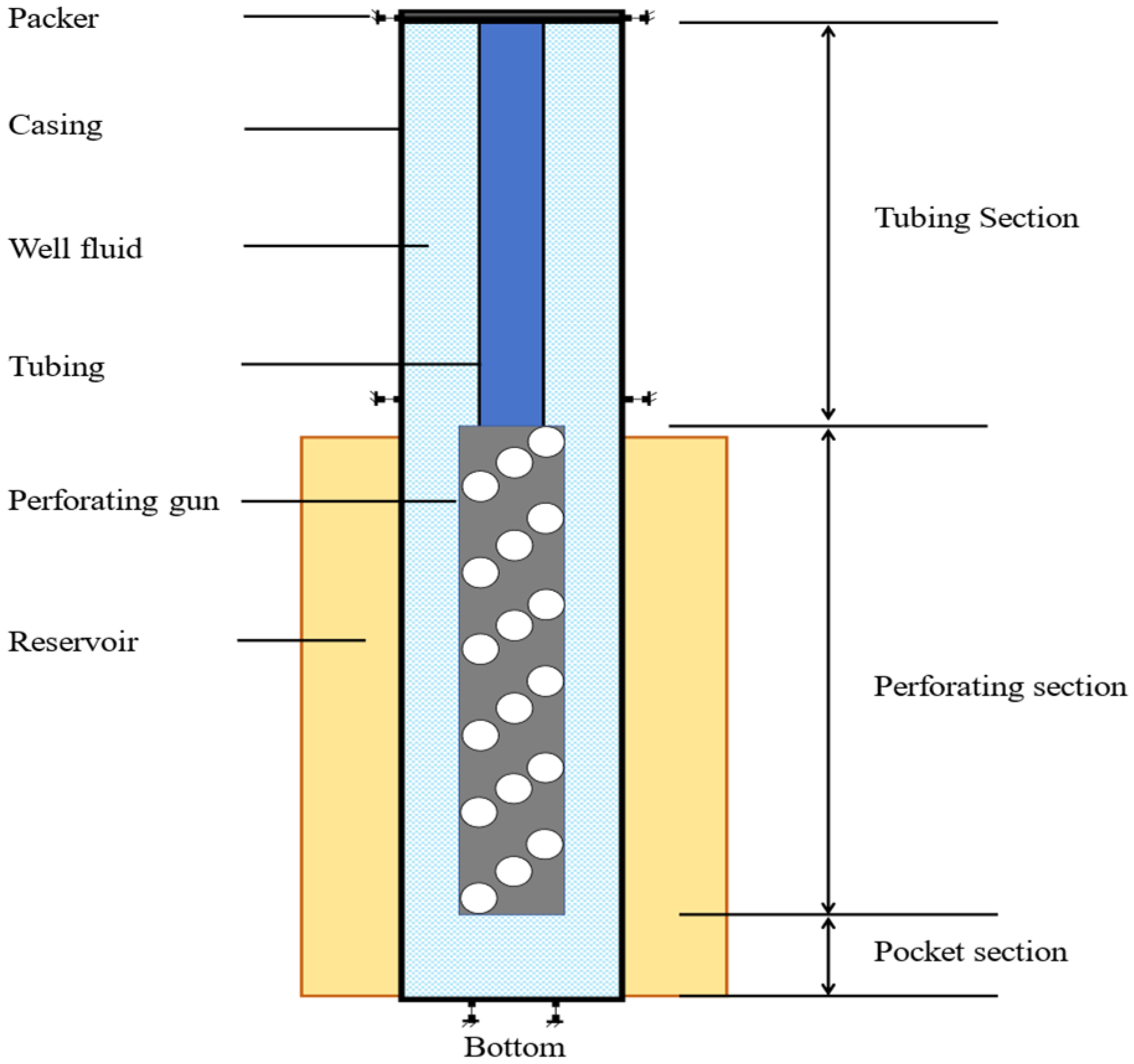
To investigate the dynamic response behavior of the perforated string under shock loading, a nonlinear dynamics finite element simulation is employed to obtain shock load data. Given the complex structure of the perforated string system and the relatively low yield strength of the tubing and packer, which makes them susceptible to deformation and failure, it is necessary to simplify the system to reduce computational costs while maintaining feasibility. Focusing on the response and large deformation of the perforated string and packer under shock loading, the components of the perforated string are treated as a unified structure. It is assumed that both the perforated string and its related components are composed of isotropic materials. The simplified perforated string system includes the packer, casing, tubing, well fluid, injection gun, reservoir and other associated components. Figure 1 illustrates the schematic representation of this simplified perforated string system.
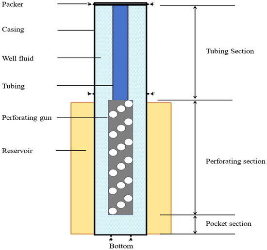
Figure 1.
Schematic diagram of the simplified perforated string system.
Based on the simplified perforated string system, combined with the dimensional parameters of the perforated string in the field and the engineering operation parameters, a full-size analysis model of the perforated string under shock loading is established and simulated. The model takes into account the dimensions of the oil pipe, casing, shotgun and other key components. Among them, the oil pipe has an outer diameter of 62 mm, the thickness of 5.51 mm and length of 20 m; the casing has an outer diameter of 244.40 mm, wall thickness of 11.95 mm and length of 40 m; the shotgun has an outer diameter of 177.80 mm, the thickness of 12.635 mm and length of 10 m; the ideal elastic–plastic model is adopted, and the modulus of elasticity of the material of the perforated string is 206 GPa.
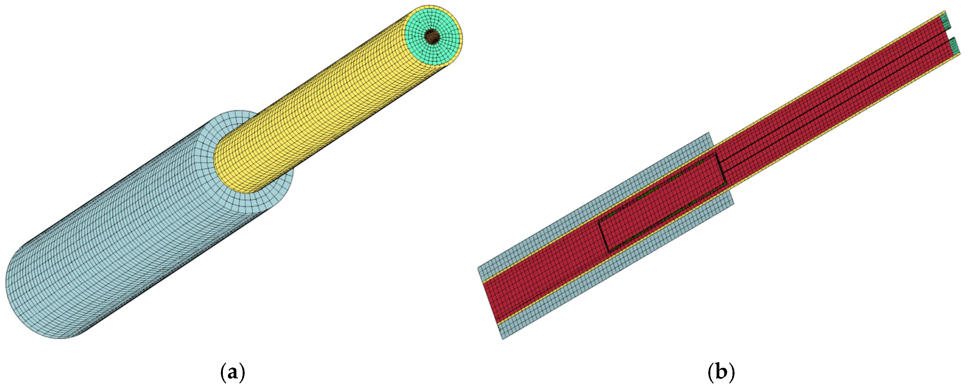
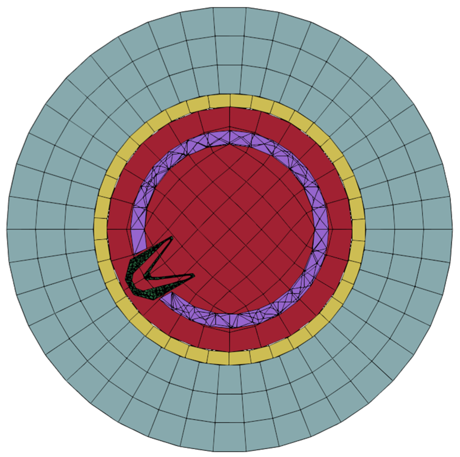
The response process of the perforated string under shock loading is highly nonlinear, and the perforated string system model adopts hexahedral mesh. Figure 2 shows the model of the perforated string system. The mesh of some regions of the model is made denser to ensure more accurate results. Figure 3 shows the perforated string system mesh and section mesh, and Figure 4 shows the pipe string cross-section mesh.

Figure 2.
Model diagram of pipe string system.
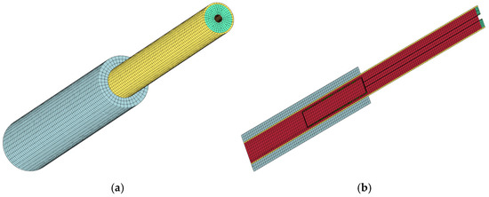
Figure 3.
Perforating string system grid diagram: (a) overall grid; (b) sectional grid.
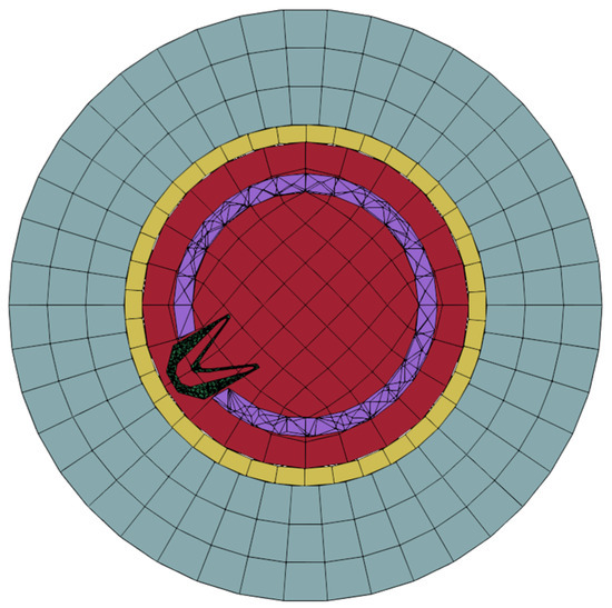
Figure 4.
The perforated string cross-section mesh.
2.3. Simulation Analysis
In the actual shock load operation, the downhole shock load peak pressure is affected by many factors, such as munition parameters, wellbore parameters, formation conditions and so on. According to the existing explosion pressure empirical formula, a preliminary analysis shows that under the premise of determining the munition performance and the structure of the tubing and pipe string system, the peak pressure of the downhole shock load is mainly closely related to the total amount of munition, wellbore pressure, effective range of explosion, rock pressure and the length of detonation interval. The following comprehensively considers the influencing factors such as the total amount of munition, wellbore pressure, effective range of explosion, rock pressure and the length of detonation interval, and conducts an analysis and calculation of the numerical simulation. The value of the total ammunition is set between 2 × 10³ g and 2 × 10⁴ g, divided into ten groups and one group is calculated for each increase of 2 × 10³ g; the value of the wellbore pressure is set between 10 MPa and 100 MPa, divided into ten groups, and one group for each 10 MPa increase is calculated. The effective range of explosion is set between 0.5 m3 and 5.0 m3 and divided into ten groups, with each increase of 0.5 m3 calculated as one group. The value of rock pressure is set between 5 MPa and 50 MPa, and it is divided into ten groups, and one group is calculated for each increase of 5 MPa. The detonation interval is set to be between 10 μs and 100 μs and divided into ten groups; one group is calculated for each additional 10 μs.
Assuming that the peak pressure of the bottom-hole impact load is determined by the above five factors, a functional relationship in the form of normalized values can be established as shown in Equation (5).
where F is the normalized value of the peak pressure of the downhole shock load; f1 is the normalized value of the total amount of munitions; Me is the peak pressure of the downhole shock load; Memax is the maximum of the peak pressure of the downhole shock load; f2 is the normalized value of the pressure of the wellbore; Pw is the pressure of the wellbore; Pwmax is the maximum of the pressure of the wellbore; f3 is the normalized value of the effective range of the explosion; Ve is the effective range of the explosion; Vemax is the maximum of the effective range of the explosion; f4 is the normalized value of the pressure of the rock; Pr is the pressure of the rock; Prmax is the maximum of the pressure of the rock; f5 is the normalized value of the length of the detonation interval; Te is the length of the detonation interval; Temax is the maximum of the length of the detonation interval.
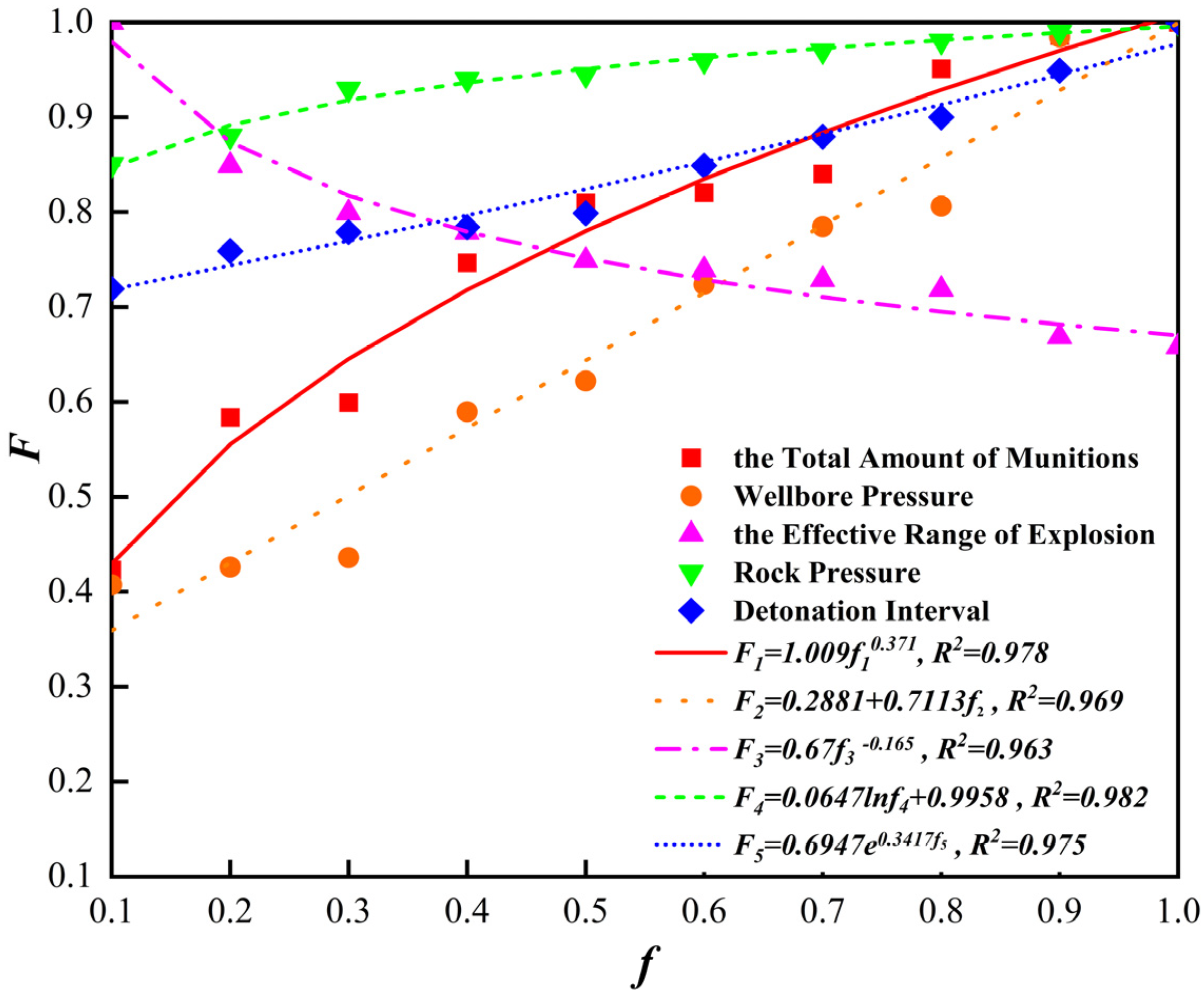
A lot of numerical simulation is carried out by changing the model parameters. By obtaining downhole perforation pressure data and applying formula (5) to process the data, the relationship curves of the total amount of ammunition, wellbore pressure, effective range of explosion, rock pressure, detonation interval time and the peak pressure of the downhole impact load can be obtained. Figure 5 shows the relationship between the total amount of ammunition, wellbore pressure, effective range of explosion, rock pressure, detonation interval time and the peak pressure of the downhole impact load. In the figure, the horizontal coordinate represents the normalized value of different influencing factors, respectively, and the vertical coordinate represents the normalized value of the peak pressure of the downhole impact load. F1 is the normalized value of the peak pressure of the downhole impact load whose variable is the total amount of ammunition. F2 is the normalized value of the peak pressure of the downhole impact load whose variable is the wellbore pressure. F3 is the normalized value of the peak pressure of downhole impact load whose variable is the effective range of explosion. F4 is the normalized value of the peak pressure of the downhole impact load whose variable is the rock pressure. F5 is the normalized value of the peak pressure of the downhole impact load whose variable is the detonation interval time.
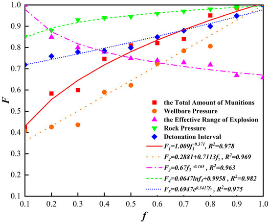
Figure 5.
Relationship between influencing factors and the peak pressure of downhole shock load.
As can be seen from Figure 5, the peak pressure of the downhole shock load increases with the total amount of munitions, and the relationship between the two is a power function. The higher the total amount of munitions, the greater the energy generated by the explosion and the higher the peak pressure of the downhole shock load. The peak pressure of the downhole shock load increases with the increase in the wellbore pressure, and the two have a linear relationship. The existence of initial pressure in the wellbore is equivalent to providing part of the foundation for the peak pressure of the downhole shock load, so the higher the wellbore pressure, the higher the peak pressure of the downhole shock load. The peak pressure of the downhole shock load with the increase in the effective range of the explosion and decrease, the two are power function relationship. The explosive effective range consists of the packer and tube and pipe string system between the confined space; the larger the explosive effective range, the larger the space affected by the blast energy, and then the peak pressure of the downhole shock load is also smaller. The peak pressure of the downhole shock load increases with the increase in rock pressure; the two have a power function relationship. The greater the rock pressure, the more difficult it is to transfer the energy generated by the blast between the strata and the energy transferred in the wellbore will increase accordingly; the peak pressure of the downhole shock load is also greater. The peak pressure of the downhole shock load with the increase in the length of the detonation interval increases; the two have a exponential function relationship. The longer the detonation interval, the more complete the release of energy from a single explosive, making the energy interference generated by the two blasts smaller and then the peak pressure of the downhole shock load is also larger.
The peak pressure of the downhole shock load and the total amount of ammunition, wellbore pressure, rock pressure and detonation interval is proportional to the relationship, and the effective range of the explosion is inversely proportional to the relationship. The greater the total amount of ammunition, the greater the borehole pressure, the greater the rock pressure, the longer the detonation interval, the smaller the effective range of the explosion and the greater the peak pressure of the downhole shock load.
2.4. Calculation Model
The downhole peak shock load pressure is related to the total amount of munitions, the wellbore pressure, the effective range of the explosion, the length of the detonation interval and the rock pressure, so the following functional relationship expression is used to predict the size of the peak shock load pressure. The effective space volume of the downhole perforation explosion is the sum of the effective space volume of the tubing section, the effective space volume of the perforating gun section and the effective space volume of the bottom-hole pocket.
where Pp is the downhole shock load peak pressure, MPa; Me is the total amount of ammunition, kg; Pw is the wellbore pressure, MPa; Ve is the effective range involved in the explosion, m3; Pr is the rock pressure, MPa; Te is the length of the detonation interval, μs; n is the number of munitions, rounds; me is a single-round charge, g/round; dc is the inner diameter of the downhole casing, m; Do is the outer diameter of the downhole pipe string, m; Dg is the hole shooting gun used outer diameter, m; Lo is the length of downhole tubing section, m; Lg is the length of downhole perforating gun, m; Lp is the pocket length, m.
Based on the finite element simulation results, the multivariate nonlinear regression analysis is carried out by considering five factors: total perforation charge, initial wellbore pressure, wellbore explosion space, detonation interval time and formation pressure. On the premise that the sum of squares of error is as small as possible, the parameters in the shock load calculation model are solved by the least square method, and the following formula can be obtained by fitting
where λ1, λ2, λ3, λ4, λ5 and λ6 are the fitting coefficient of the shock load calculation model.
Due to the detonation interval length, the rock pressure for the shock load under the action of the shock loading of the pipe string load peak pressure size of the impact effect is relatively small compared to other factors, the two factors for the assignment of the value of the processing, so that Te → 0 μs, Pr → 1 MPa, the above formula can be transformed into
where ρ is the density of injection fluid used, kg/m3; H0 is the artificial well bottom position, m; H1 is the bottom of the injection hole boundary position, m; H2 is the injection hole top boundary position, m; H3 is the packer seating position, m; a is the hole density, holes/m; Dc is the outer diameter of the casing, m; δc is the casing wall thickness, m.
3. Safety Evaluation Method
Under the actual perforating shock loading, the dynamic response of the pipe string is obvious in the axial direction, and the axial direction is mainly subjected to tension or pressure. If the axial load applied exceeds the failure strength of the test string, the string will buckle or break. On the other hand, the axial or circumferential direction of the test pipe string is mainly subjected to shear or torsion force; if the applied radial or circumferential load exceeds the destructive strength of the test pipe string, the pipe string will be sheared or deformed. Because the radial or circumferential displacement of the pipe string is constrained by the casing, the change in radial or circumferential displacement is much smaller than the axial displacement, so it is more important to pay attention to the axial displacement and axial force. Under the action of shock loading, the pipe string is subjected to axial tension and compression as the main force on the pipe string. In terms of the structural safety mechanics of the pipe string, compared with the dynamics, the current theory and standard of statics is more mature. Therefore, the use of hydrostatic strength theory to assess the safety of the pipe string can avoid the limitations of dynamics on the one hand, and on the other hand, it can also take into account the shock load [27,28,29,30,31].
3.1. Safety Strength Theory
The deformation energy theory (the fourth strength theory) refers to the fact that when the deformation energy density reaches the limit value of the material, the material will yield at a certain position [32,33,34,35,36,37]. This theory is chosen as the basis for judging the damage of the pipe string, and the specific contents are as follows:
where σ1, σ2 and σ3 are the first, second and third principal stresses, MPa; μ is Poisson’s ratio; [σ] is the permissible stress, MPa.
3.2. Judgment Criteria for Perforated String Buckling Under Pressure
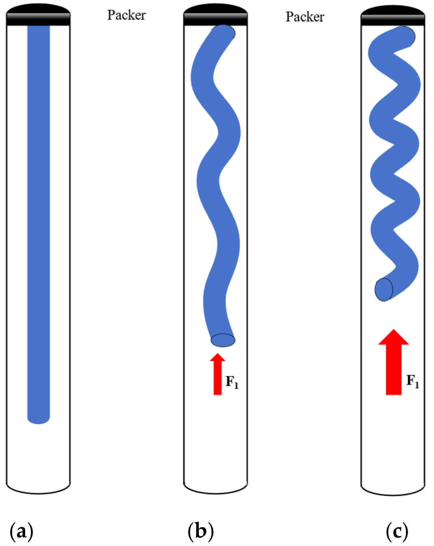
Similarly to the static analysis of the pipe string, it can be considered that the pipe string will be subjected to axial shock load under the constraint of the casing, and the pipe string buckling behavior is mainly divided into dynamic sinusoidal buckling behavior and dynamic spiral buckling behavior. In order to simplify the model of pipe string, first the joints and other components should be ignored; then, the pipe string can be regarded as a whole structure since assuming that the material of the pipe string is isotropic, the axis of the pipe string and the centerline of the casing is in the same line; the pipe string is straight and stable, and the internal and external pressure is balanced; the bottom of the pipe string is subjected to the axial dynamic shock load. Figure 6a shows the schematic diagram of the pipe string without buckling behavior, and Figure 6b,c show the schematic diagram of the dynamic sinusoidal buckling behavior and the dynamic spiral buckling behavior of the pipe string, respectively.
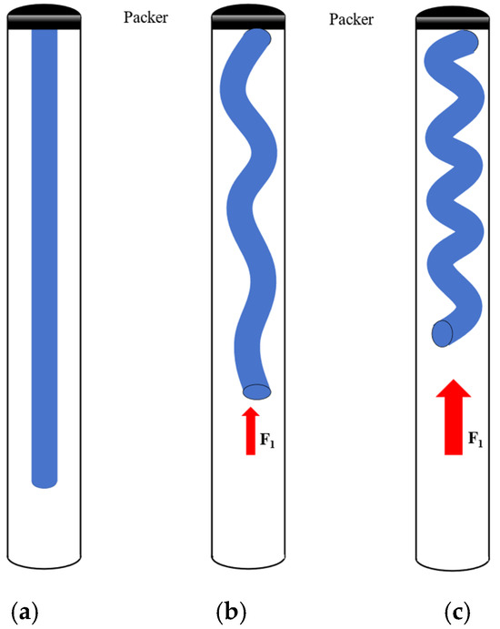
Figure 6.
Schematic diagram of pipe string buckling behavior: (a) the schematic diagram of the pipe string without buckling behavior; (b) the schematic diagram of the dynamic sinusoidal buckling behavior of the pipe string; (c) the schematic diagram of the dynamic spiral buckling behavior of the pipe string.
The magnitude of the shock load pressure on the pipe string at the instant of shock loading is
where Fc is the impact pressure on the pipe string, N; do is the inner diameter of the oil pipe in the shot hole section, m.
The empirical formula for calculating the shock load obtained by fitting can be obtained by substituting into the above formula:
Considering only the pipe string subjected to axial shock load, when the impact pressure acting on the bottom of the pipe string exceeds the range that can be withstood by the pipe string itself, the pipe string will be subjected to a buckling behavior. Based on the safety coefficient method, comparing the impact pressure at the bottom of the pipe string under shock loading with the size of the critical load of the pipe string under buckling can be used as a criterion for determining the buckling of the pipe string under pressure.
The criterion for judging the pipe string without buckling is
where n1 is the buckling safety factor of the pipe string; Fcb is the critical buckling load of the pipe string, N; Ep is the modulus of elasticity, Pa; Ip is the cross-section moment of inertia, m4; qp is the floating weight of the line, N/m; r is the inner diameter of the pipe string, m.
3.3. Judgment Criteria for Tension Fracture of Perforated String
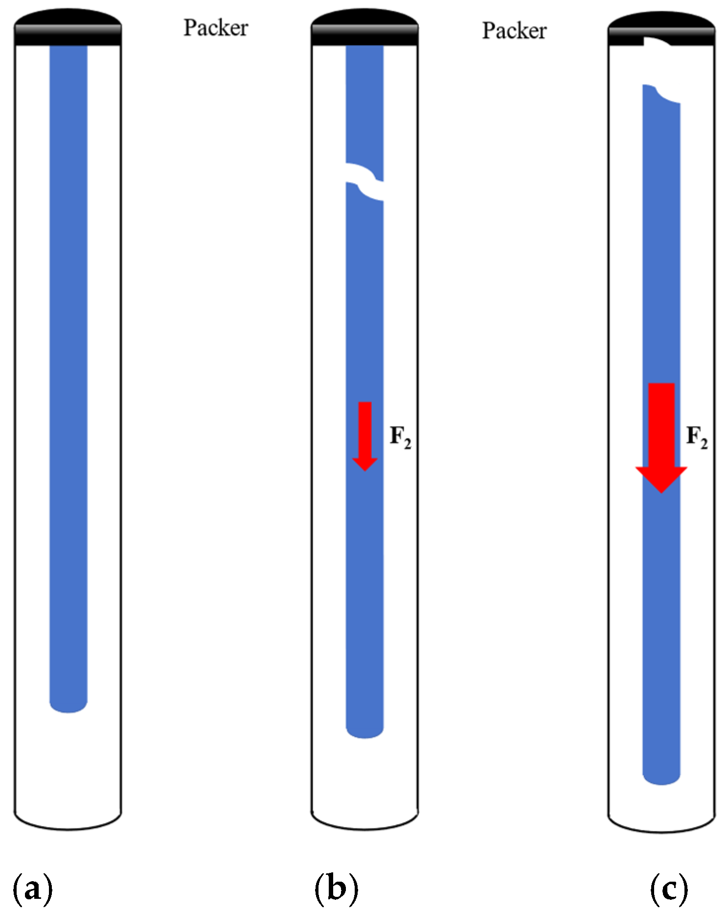
Similarly to the static analysis of the pipe string, it can be assumed that the position above the neutral point of the pipe string is mainly subjected to tension, and the pipe string is subjected to an axial tensile load under the constraints of the casing, and it is easy to deform and fracture when the tensile load exceeds the strength range that can be withstood by the pipe string itself. In order to simplify the model of the pipe string, first ignore the joints and other components; then, the pipe string can be regarded as a whole structure since assuming that the material of the pipe string is isotropic, the axis of the pipe string and the centerline of the casing is in the same line; the pipe string is straight and stable, and the internal and external pressure is balanced; the bottom of the pipe string is subjected to the axial dynamic shock load. Figure 7a shows the schematic diagram of the behavior of the pipe string without tensile fracture, and Figure 7b,c show the schematic diagram of the fracture behavior of the pipe string in axial tension and the fracture behavior of the center string of the packer, respectively.
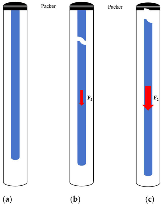
Figure 7.
Schematic diagram of pipe string tension behavior: (a) the schematic diagram of the behavior of the pipe string without tensile fracture; (b) the schematic diagram of the fracture behavior of the pipe string in axial tension; (c) the schematic diagram of the fracture behavior of the center string of the packer.
In the process of the propagation of the shock wave in the fluid medium, it will interact with the structure in the wellbore, and when the shock wave propagates to the rubber wall of the packer, reflection and refraction will occur, the rubber wall of the packer will be in the fluid medium and there will be two interfaces above and below. From the basic theory of shock wave, it can be seen that after the shock load is reflected and transmitted by the packer, the pressure on the lower interface of the packer is the sum of the incident pressure on the lower interface and the reflected pressure on the lower interface. The expression for the pressure at the lower interface of the packer is
where Pi and Pr are the incident and reflected pressures at the interface under the packer, respectively, MPa.
In an enclosed space, the shock wave not only travels forward but also reflects when it encounters the packer. That is, the original shock wave and the reflected shock wave may meet at the same location and superposition, resulting in a pressure at that point that is twice the pressure of the original shock wave. In order to simplify the analysis process, the lower packer interface is considered to be the location where dual pressure is applied. The formula for calculating the axial force of pipe string under shock loading is as follows:
Under shock loading, the effective axial tensile force of the pipe string is composed of two parts, including the axial tensile force caused by the self-weight and the instantaneous tensile force caused by the shock load, and the tensile force at the upper end of the pipe string of the deep well long tubing is larger. Based on the safety coefficient method, comparing the effective axial tensile force of the pipe string under shock loading with the magnitude of the tensile strength of the pipe string can be used as a criterion for the judgment of fracture of the pipe string under tension.
The following judgment criteria are used to ensure that the pipe string does not break.
The pipe string tensile strength calibration formula:
Strength calibration equations for the pipe string where the surrounding medium is the injection fluid:
where Fze is the effective axial tensile force of the pipe string under shock loading, N; n2 is the tensile safety coefficient of the pipe string; Fs is the tensile strength of the pipe string, N; K is the safety coefficient of the material; Lt is the length of the pipe string, m.
4. Field Case Analysis
4.1. Case 1: XX-1 Well in the Southwest Region
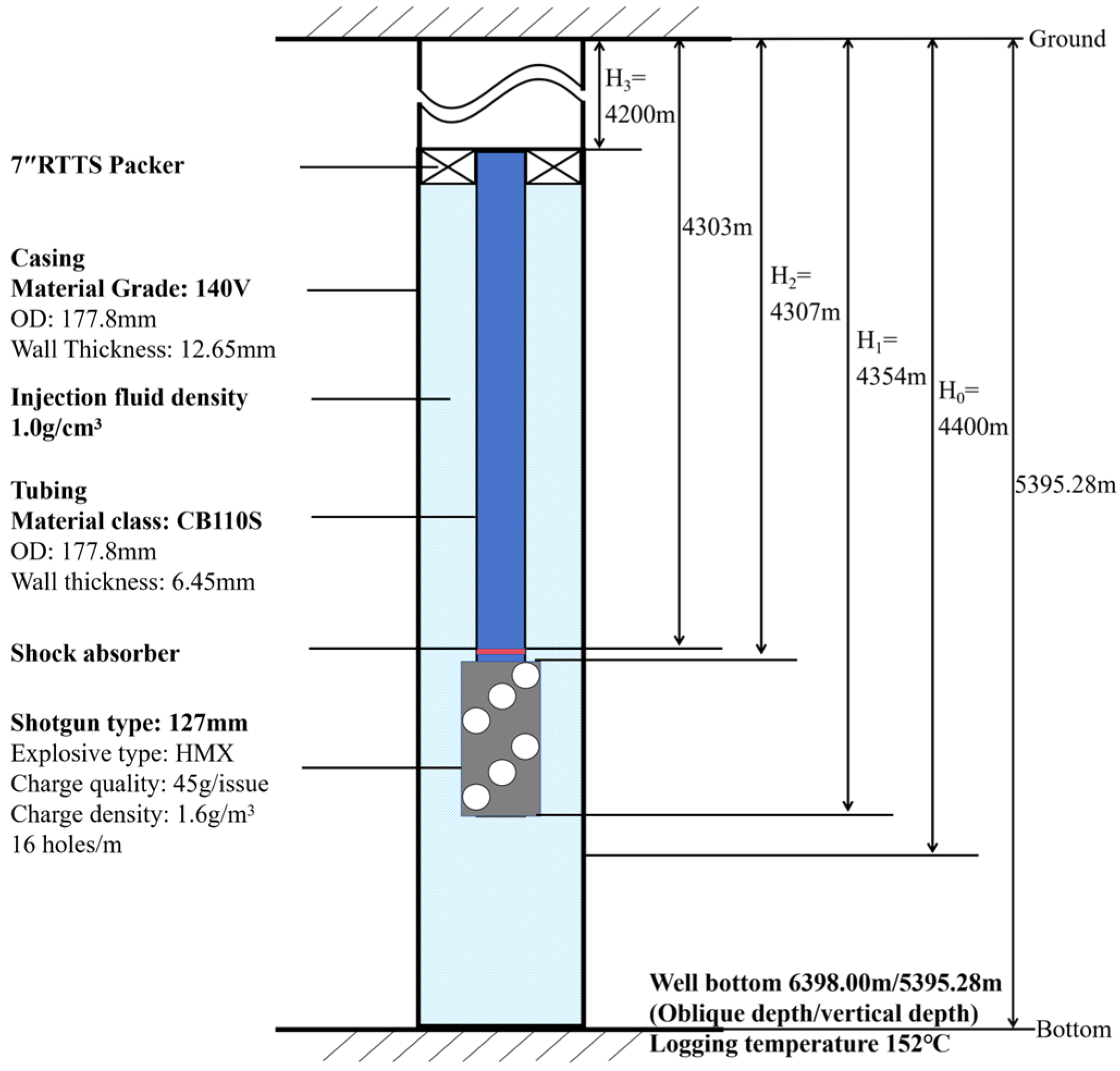
Considering example A in southwest China, the safety analysis of a pipe string under shock loading has been carried out. The key parameters required for the analysis of pipe string safety under shock loading include perforation charge parameters, perforation parameters, casing parameters of the perforating section, tubing parameters of the perforating section, packer parameters, construction parameters, reservoir parameters and formation parameters, as shown in Table 1. Figure 8 is a schematic diagram of the pipe string structure of example well A in southwest China.

Table 1.
Key parameters for pipe string safety analysis in example well A.
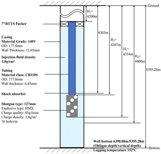
Figure 8.
Pipe string structure diagram of example well A in southwest China.
Using the peak pressure calculation model of pipe string under shock loading in this paper, the relevant parameters of the example well are substituted into Equation (10) for analyzing and calculating, and the resulting peak pressure calculation of pipe string under shock loading is 69.52 MPa.
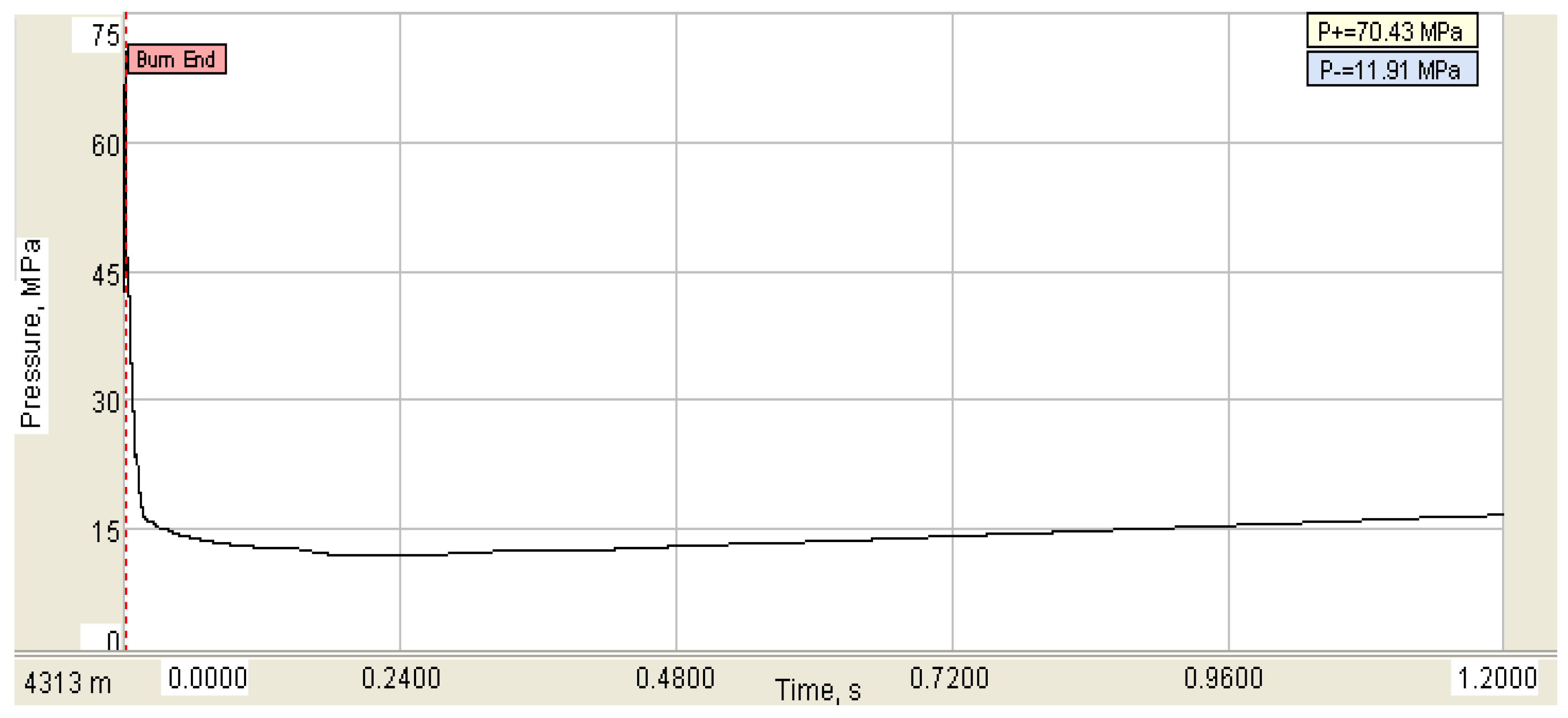
A commercial software for analyzing wellbore dynamics was used to analyze the dynamic strength safety of the string under the shock loading of the well in this example. The peak value of the maximum shock load in clear water is about 70.43 MPa, as shown in Figure 9.
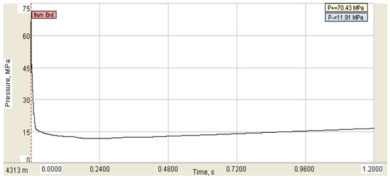
Figure 9.
Simulation result of shock load.
The calculation results of the peak pressure model under shock loading have been compared with those predicted by the commercial software. The calculation results are as follows:
The error between the peak pressure calculated by the model and the result calculated by the commercial software is less than 10%, and the error is within the allowable range. According to the established flexion mechanical check model and tensile strength mechanical check model, the safety of the pipe string under shock loading is checked. The calculated maximum tensile force of the pipe string is 244.45 kN, the tensile safety factor is 5.11 and no pulling phenomenon will occur. The maximum impact pressure of the string is 103.97 kN, the buckling safety factor is 1.62 and the buckling phenomenon will not occur.
4.2. Case 2: XX-2 Well in the Southwest Region
Considering example B in southwest China, the safety analysis of pipe string under shock loading is carried out. The key parameters required for the analysis of pipe string safety under shock loading include perforation charge parameters, perforation parameters, casing parameters of the perforating section, tubing parameters of the perforating section, packer parameters, construction parameters, reservoir parameters and formation parameters, as shown in Table 2.

Table 2.
Key parameters for pipe string safety analysis in example well B.
Using the peak pressure calculation model of pipe string under shock loading in this paper, the relevant parameters of the example wells are substituted into Equation (10) for analyzing and calculating, and the result of the peak pressure calculation of pipe string under shock loading is 82.93 MPa.
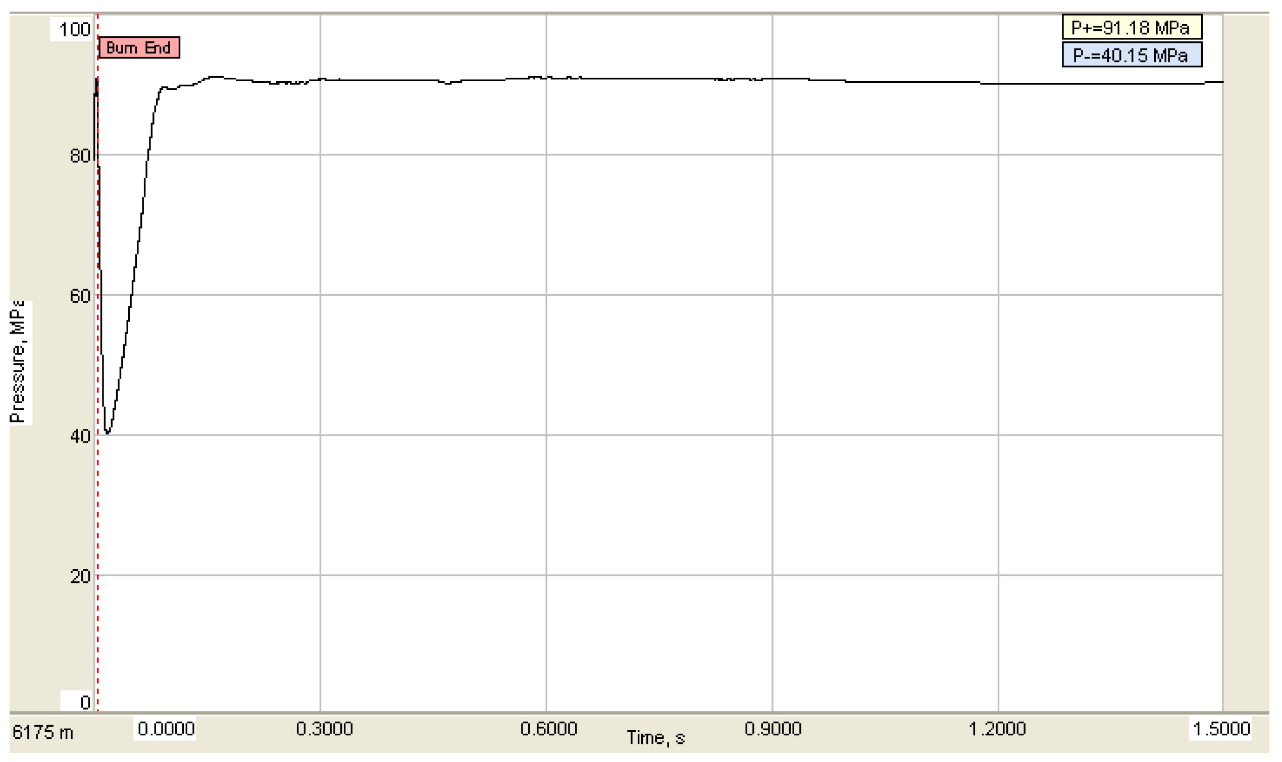
A commercial software for analyzing wellbore dynamics was used to analyze the dynamic strength and safety of the string under the shock loading of this example well. The peak value of the maximum shock load is about 91.18 MPa under 1.30 g/cm3 of working liquid without a solid phase, as shown in Figure 10.
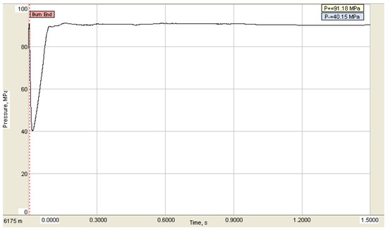
Figure 10.
Simulation result of shock load.
The calculation results of the peak pressure model under shock loading have been compared with those predicted by the commercial software. The calculation results are as follows:
The error between the peak pressure calculated by the model and the result calculated by the commercial software is less than 10%, and the error is within the allowable range. According to the established flexion mechanics check model and tensile strength mechanical check model, the safety of the pipe string under shock loading is checked. The calculated maximum tensile force of the pipe string is 366.33 kN, the tensile safety factor is 3.89 and no pulling phenomenon will occur. The maximum impact pressure of the pipe string is 101.55 kN and the buckling safety factor is 2.04, without a buckling phenomenon.
In summary, compared with the result of the commercial software for analyzing wellbore dynamics, the error margin of the calculation result of the peak pressure of the pipe string under shock loading is small, indicating that the model can achieve the accuracy of the calculation and prediction of the peak pressure of the pipe string under shock loading within the allowed error range, and can meet the engineering requirements. Therefore, the model can provide significant guiding for the safety evaluation of pipe string under shock loading to a certain extent.
5. Conclusions
(1) The factors that influence the peak pressure of a downhole impact load are explored. Numerical simulation shows that the peak pressure of a downhole impact load increases with the increase in the total amount of ammunition, the increase in wellbore pressure, the increase in rock pressure and the increase in the detonation interval. With the increase in effective explosion range, the peak pressure of a downhole impact load decreases.
(2) A numerical simulation-based shock loading calculation model is developed for the safety evaluation of perforated string under dynamic load. The analysis of two wells in southwest China shows that the model has high accuracy, and the calculated peak bottom hole pressures are 69.52 MPa and 82.93 MPa, respectively. The results show that the error margin is less than 10% compared with the results of foreign commercial wellbore dynamic software, which confirms the reliability of the model and that it is suitable for engineering applications. This validation highlights the model’s ability to predict key parameters such as axial forces and peak pressures under complex impact loads.
(3) A hybrid safety assessment methodology integrating static strength theory (fourth strength theory) and dynamic response analysis was proposed. By establishing buckling and tensile failure criteria, the model effectively evaluated risks such as pipe string buckling (safety factor >1.6) and tensile fracture (safety factor >3.8) under shock loads. This dual approach bridges the gap between theoretical dynamics and practical static standards, offering engineers a robust tool for real-world safety design and risk mitigation.
(4) At present, there is still a lot of room for improvement in the analysis of pipe dynamics. The study of dynamic response mechanisms is of great significance in solving the difficult problems in the field of pipe safety, and it can also promote the innovation and improvement of theories and methods in the field of pipe mechanics in oil and gas well engineering and help develop more effective measures to ensure the safety and reliability of operations.
Author Contributions
Writing—review and editing, Q.D. and D.Y.; Conceptualization, M.Y.; Formal analysis, G.C. and D.F.; Methodology, B.J. All authors have read and agreed to the published version of the manuscript.
Funding
This study was supported by open foundation project of the Key Laboratory of Polar Geology and Marine Mineral Resources (China University of Geosciences, Beijing), Ministry of Education (Number: PGMR-2024-106); the Key Program of the Hubei Provincial Department of Education, No. D20221303; the Natural Science Foundation of Hubei Province, No. 2022CFB700; and the Open Foundation of Cooperative Innovation Center of Unconventional Oil and Gas, Yangtze University (Ministry of Education & Hubei Province), No. UOG2024-06.
Data Availability Statement
The raw data supporting the conclusions of this article will be made available by the authors on request.
Conflicts of Interest
Authors Gang Cui, Dongyang Fan and Bo Jia were employed by the company China Petroleum Group Bohai Drilling Engineering Co., Ltd. The remaining authors declare that the research was conducted in the absence of any commercial or financial relationships that could be construed as a potential conflict of interest.
References
- Deng, Q.; Zhang, H.; Li, J.; Hou, X.; Wang, H. Study of Downhole Shock Loads for Ultra-Deep Well Perforation and Optimization Measures. Energies 2019, 12, 2743. [Google Scholar] [CrossRef]
- Liu, J.; Jian, Y.; Chen, Y.; Tang, K.; Ren, G.; Chen, J. Shock vibration response characteristic of perforating tubing string in ultra-deep wells. Geoenergy Sci. Eng. 2023, 228, 212008. [Google Scholar] [CrossRef]
- Wang, H.; Zhang, C.; Zhou, B.; Xue, S.; Wang, F. Prediction of the Productivity Ratio of Perforated Wells Using Least Squares Support Vector Machine with Particle Swarm Optimization. Appl. Sci. 2023, 13, 12978. [Google Scholar] [CrossRef]
- Jiang, J.; Deng, Q.; Yang, D.; Qi, G.; Zhang, F.; Tan, L. Numerical Simulation Study on the Damage Mechanism of the Combined Perforating Well Testing Tubing in Ultra-Deep Wells. Processes 2024, 12, 380. [Google Scholar] [CrossRef]
- Deng, Q.; Zhang, H.; Chen, A.; Li, J.; Hou, X.; Wang, H. Effects of perforation fluid movement on downhole packer with shock loads. J. Pet. Sci. Eng. 2020, 195, 107566. [Google Scholar] [CrossRef]
- Chen, F.; Chen, H.; Tang, K.; Ren, G. Impacts and countermeasures of shock loads on operating pipe column. Nat. Gas Ind. 2010, 30, 61–65. [Google Scholar]
- Baumann, C.E.; Pesantes, E.; Guerra, J.P.; William, A.; Williams, H.A. Reduction of Perforating Gunshock Loads. SPE Drill. Complet. 2012, 27, 65–74. [Google Scholar] [CrossRef]
- Lu, X.; Wang, S.S.; Ma, F.; Zhou, H. Dynamic response test of perforated pipe column under blast impact. Sci. Technol. Eng. 2014, 14, 53–56, 92. [Google Scholar]
- Zhang, W.; Xu, C.; Li, M.F.; Zhang, L.; Wang, G.Q. Transient response and stress intensity analysis of pipe column in shot hole section. Pet. Mach. 2017, 45, 90–94, 110. [Google Scholar]
- Li, M.F.; Xu, F.; Dou, Y.H. Analysis of dynamic response of pipe column in shot hole section under blast shock load. Vib. Shock 2019, 38, 185–191, 222. [Google Scholar]
- Zhang, J.; Liu, H.; Li, M.; Dou, Y. Theoretical and numerical analysis of the dynamic response of the shot hole pipe column under the action of poly energy shot hole blast load. Mech. Des. Manuf. Eng. 2019, 48, 109–113. [Google Scholar]
- Yang, W.; Li, H.; Lin, Y.; Ren, S.; Zhang, Z.; Xu, S.; Li, F. Mechanical analysis of pipe column vibration in shot hole section under the influence of multiple factors. Vib. Shock 2024, 43, 223–229. [Google Scholar]
- Zhang, P.; Zhang, M.Y.; Zhang, W.B. Study on the kinetic characteristics of perforated tubular column. Oil Gas Well Test. 2024, 33, 1–8. [Google Scholar]
- Zhou, X.; Liu, J.; Jian, Y.; Chen, Y.; Liang, S. Vibration safety analysis of cable shot hole in horizontal well. Pet. Mach. 2024, 52, 41–50. [Google Scholar]
- Deng, Q.; Jiang, J.; Yang, D.; Han, H.; Qi, G. Dynamic analysis and optimization of perforated tubing strings in deep-water wells under diverse operating conditions. Ocean. Eng. 2025, 322, 120535. [Google Scholar] [CrossRef]
- Mao, L.; He, X.; Zhang, J. Dynamic behavior and failure analysis of perforating string under explosive load. Eng. Fail. Anal. 2022, 136, 106222. [Google Scholar] [CrossRef]
- Ding, L.; Chen, W.; Han, C.; Xue, Y.; Lei, Q. Study on explosion energy conversion of a perforating shaped charge during perforation detonation. SPE J. 2024, 29, 2938–2952. [Google Scholar] [CrossRef]
- Yin, H.D.; Li, S.Y.; Zhang, J.J. Analysis of force on joint work tubing column of shot hole testing and protection technology of downhole instruments. Oil Drill. Technol. 2003, 25, 61–63. [Google Scholar]
- Chernyshov, S.; Popov, S.; Wang, X.; Derendyaev, V.; Yang, Y.; Liu, H. Analysis of Changes in the Stress–Strain State and Permeability of a Terrigenous Reservoir Based on a Numerical Model of the Near-Well Zone with Casing and Perforation Channels. Appl. Sci. 2024, 14, 9993. [Google Scholar] [CrossRef]
- Lercari, M.; Gonzalez, S.; Espinoza, C.; Longo, G.; Antonacci, F.; Sarti, A. Using mechanical metamaterials in guitar top plates: A numerical study. Appl. Sci. 2022, 12, 8619. [Google Scholar] [CrossRef]
- Liu, X.; Li, J.; Liu, G.; Lian, W.; Wang, B.; Yang, H. Numerical study on damage law and influencing factors of cement sheath under perforation conditions. Pet. Sci. Technol. 2024, 42, 613–633. [Google Scholar] [CrossRef]
- Lian, Z.; Mou, Y.; Liu, Y.; Xu, D. Research on the buckling behavior of oil tubing column in high temperature and high pressure ultra-deep gas wells. Nat. Gas Ind. 2018, 38, 89–94. [Google Scholar]
- Lee, E.L.; Hornig, H.C.; Kury, J.W. Adiabatic Expansion of High Explosive Detonation Products; U.S. Department of Energy Office of Scientific and Technical Information: Richland, WA, USA, 2018. [Google Scholar]
- Nan, Y.; Jiang, J.; Wang, S.; Men, J. A parameterization method of JWL equation closed with blast parameter. Explos. Shock 2015, 35, 157–163. [Google Scholar]
- Hallquist, J.O. LS-Dyna Theory Manual; Livermore Software Technology Corporation: Livermore, CA, USA, 2006. [Google Scholar]
- Fang, Q.; Kong, X.; Wu, H.; Gong, Z. Method for determining parameters of Holmquist-Johnson-Cook model for rocks. Eng. Mech. 2014, 31, 197–204. [Google Scholar]
- Deng, Q. Safety Analysis for Downhole Wellbore During Perforating. Ph.D. Thesis, China University of Petroleum (Beijing), Beijing, China, 2020. [Google Scholar]
- Cole, R.H. Underwater Explosions; Princeton University Press: Princeton, NJ, USA, 1948; pp. 10–50. [Google Scholar]
- Deng, Q.; Zhang, H.; Li, J.; Dong, J.; Wang, H.; Hou, X. Safety Distances of Packers for Deep-Water Tubing-Conveyed Perforating. In Proceedings of the Offshore Technology Conference, Houston, TX, USA, 30 April–3 May 2018; p. OTC-28770-MS. [Google Scholar]
- Schatz, J.F.; Folse, K.C.; Fripp, M.; Dupont, R. High-Speed Pressure and Accelerometer Measurements Characterize Dynamic Behavior During Perforating Events in Deepwater Gulf of Mexico. In Proceedings of the SPE Annual Technical Conference and Exhibition, Houston, TX, USA, 26–29 September 2004; p. SPE-90042-MS. [Google Scholar]
- Bale, D.S.; Satti, R.P.; Ji, M.; Howard, J.J. A Next-generation Shock-capturing, Multi-phase Flow Simulator for Perforating Applications in HPHT Environment. In Proceedings of the SPE Deepwater Drilling & Completions Conference, Galveston, TX, USA, 14–15 September 2016; p. SPE-180283-MS. [Google Scholar]
- Lubinski, A.; Althouse, W.S.; Logan, J.L. Helical Buckling of Tubing Sealed in Packers. J. Pet. Technol. 1962, 16, 655–670. [Google Scholar] [CrossRef]
- Paslay, P.R.; Bogy, D. The Stability of a Circular Rod Laterally Constrained to Be in Contact with an Inclined Circular Cylinder. J. Appl. Mech. 1964, 31, 605–610. [Google Scholar] [CrossRef]
- Miska, S.; Cunha, J.C. An Analysis of Helical Buckling of Tubulars Subjected to Axial and Torsional Loading in Inclined Wellbores. SPE Prod. Oper. Symp. 1995, 4, 173–180. [Google Scholar]
- Mitchell, R.F. Effects of Well Deviation on Helical Buckling. SPE Drill. Complet. 2013, 12, 63–70. [Google Scholar] [CrossRef]
- Schatz, J.F.; Haney, B.L.; Ager, S.A. High-speed downhole memory recorder and software used to design and confirm perforating/propellant behavior and formation fracturing. In Proceedings of the SPE Annual Technical Conference and Exhibition, Houston, TX, USA, 3–6 October 1999. [Google Scholar]
- Li, Z.; Zhang, C.; Song, G. Research advances and debates on tubular mechanics in oil and gas wells. J. Pet. Sci. Eng. 2017, 151, 194–212. [Google Scholar] [CrossRef]
Disclaimer/Publisher’s Note: The statements, opinions and data contained in all publications are solely those of the individual author(s) and contributor(s) and not of MDPI and/or the editor(s). MDPI and/or the editor(s) disclaim responsibility for any injury to people or property resulting from any ideas, methods, instructions or products referred to in the content. |
© 2025 by the authors. Licensee MDPI, Basel, Switzerland. This article is an open access article distributed under the terms and conditions of the Creative Commons Attribution (CC BY) license (https://creativecommons.org/licenses/by/4.0/).

