Article

Influence of Degree of Saturation on Soil–Pile Interactions for Piles in Expansive Soils

by
Kuo Chieh Chao
1,
A-Nanya Chaladthanyakit
2 and
Taskid Hossain Asif
3,*
1
Department of Civil and Infrastructure Engineering, School of Engineering and Technology, Asian Institute of Technology, Pathumthani 12120, Thailand
2
Electricity Generating Authority of Thailand, Nonthaburi 11130, Thailand
3
Department of Civil Engineering, School of Engineering. Ahsanullah University of Science and Technology, Dhaka 1208, Bangladesh
*
Author to whom correspondence should be addressed.
Appl. Sci. 2025, 15(13), 7102; https://doi.org/10.3390/app15137102
Submission received: 10 April 2025 / Revised: 12 June 2025 / Accepted: 13 June 2025 / Published: 24 June 2025
(This article belongs to the Special Issue Unsaturated Soils: Testing and Modelling, 2nd Edition)

Abstract

Conventional designs of pile foundations for houses on expansive soils adopt conservative approaches by using swelling pressure measured in oedometer tests to compute pile uplift force. However, in practice, piles are often installed in unsaturated soils, where changes in moisture content influence soil behavior. Increasing moisture in expansive soils reduces matric suction, increases soil volume, and induces swelling pressure, all of which affect uplift shear stress. This study investigates the impact of varying degrees of saturation on pile uplift force through a series of laboratory tests on single-pile models. The results of the experimental investigation indicate that uplift force developed along the pile shaft due to the wetting of expansive soils exhibits a hyperbolic trend. A significant portion of the uplift force developed during the early stage of the heaving process. Back-calculation analyses using theoretical equations reveal that the coefficient of uplift, α, and the swelling pressure ratio, β, increases as the initial degree of saturation of soil specimens increases, with a change of less than 10% within the tested range. These findings suggest that constant values of the α and β parameters can be used for pile design in expansive soils, even under unsaturated conditions. Nonetheless, the influence of other factors, such as pile dimensions, pile materials, and soil properties, on the α and β values should be investigated to improve the accuracy of pile design in expansive soil conditions.

1. Introduction

Expansive soils present a significant challenge in geotechnical engineering due to their tendency to undergo volume changes with variations in moisture content. The resulting swelling or shrinking of these soils can cause substantial damage to building structures and their foundations. Montmorillonite, a clay mineral commonly found in expansive soils, exhibits expansive characteristics due to its weak chemical bonds and high susceptibility to water [1,2,3]. Consequently, understanding the behavior of expansive soils and accurately designing pile foundations to withstand their effects is crucial for ensuring the stability and integrity of structures.
In pile design for expansive soils, it is essential to compute the uplift force acting on the pile shaft. The total uplift force on piles within the design active zone can be calculated using the total stress method, effective stress method, and analytical or finite element methods [4]. The depth of the design active zone is defined as the depth (zone) of soil expected to become wetted by the end of the design life [5]. In the total stress method, the interface shear stress is equal to an empirical coefficient multiplied by the undrained shear strength of the soil [6,7]. Nguyen et al. (2022) [8] demonstrated that total stress analysis provides results that closely align with observed data. In the effective stress method, the interface shear stress is calculated based on the normal effective stress on the pile, soil cohesion, and the interface friction angle between the pile shaft and the soil [5,7,9,10,11,12,13]. The effective stress method is commonly used in geotechnical engineering practice and will be discussed in further detail in Section 2 of this paper. The analytical and finite element methods can be used to evaluate elastic solutions between the movement of the soil and the pile system. Poulos and Davis (1980) [10], Nelson and Miller (1992) [14], and Nelson et al. (2015) [5] presented design charts for evaluating the uplift force and movement of piles in expansive soils.
The effective stress method commonly used in geotechnical engineering practice utilizes the swelling pressure measured in oedometer tests to compute the pile uplift force. In these tests, soil specimens are inundated with water in an oedometer to measure the swelling pressure of expansive soils. However, this conventional design practice, based on fully wetted conditions, may not fully capture the behavior of piles in unsaturated expansive soils. Changes in moisture content can significantly impact the soil’s volume, swelling pressure, and matric suction, consequently influencing the uplift shear stress in pile design [15,16,17,18].
Limited research has quantified the influence of saturation changes on pile design in expansive soils. To address this knowledge gap, this research paper presents a comprehensive investigation into the influence of moisture content on pile design for expansive soils. Awadalseed et al. (2024) [19] previously examined the behavior of pile–soil interaction in expansive soils subjected to water infiltration. On the other hand, the primary objective of this present study is to determine the relationship between moisture content, swelling pressure, matric suction, and pile design parameters under unsaturated conditions. The research methodology involves conducting laboratory tests on single-pile models, subjecting them to varying degrees of saturation representative of real-world conditions. By carefully measuring and analyzing the data, this study aims to provide a better understanding of pile behavior in unsaturated expansive soils.

2. Total Uplift Force on Pile in Expansive Soils

In the effective stress method, Poulos and Davis (1980) [10] proposed a simple equation for pile design based on the adhesion between the soil and the pile. The equation calculates the total tension force, T, used in pile design by integrating the adhesion, τa, along the pile shaft:
T = 0 h π d τ a d z
where τa represents the adhesion between the soil and the pile.
To evaluate the load that would occur if adhesion were mobilized along the entire pile shaft (PFS), the equation integrates the adhesion along the length of the pile:
P F S = 0 L π d τ a d z
For saturated soil under drained conditions, the adhesion, τa, can be determined using the following equation, which involves effective cohesion, C a , and the normal effective stress acting on the pile shaft, K s σ v , along with the friction angle, ϕ a :
τ a = C a + K s σ v tan ϕ a
Thus,
P F S = π 0 L d C a + K s σ v tan ϕ a d z
However, for unsaturated conditions, the shear strength of the soil is defined by the constitutive surface of unsaturated soil, which depends on matric suction (uafuwf) and net normal stress (σnfσaf). The widely used Fredlund’s (1993) [20] equation expresses the shear strength of unsaturated soil using the effective cohesion, C′, net normal stress, σnf, matric suction, (uafuwf), and the friction angle contributed by soil suction, ϕb:
τ f = C + ( σ n f u a f ) tan ϕ + ( u a f u w f ) tan ϕ b
Hamid and Miller (2009) [21] proposed an equation to determine the shear strength of non-expansive unsaturated soil, which considers the interface friction angle, ϕ′, and volumetric water content, θ:
τ f = C a + ( σ n f u a f ) tan ϕ + ( u a f u w f ) tan ϕ θ θ r θ s θ r
where
C a is the effective cohesion of soil;
(σnfσaf) is the net normal stress;
ϕ’ is the interface friction angle between soil and pile;
(uafuwf) is the matric suction of soil;
θ is the current volumetric water content;
θr is the residual volumetric water content (in this case, θr = 0);
θs is the saturated volumetric water content.
The migration of water into expansive soils involves complex changes in soil stress state parameters [22,23]. Additionally, Nelson et al. (2015) [5] emphasized that the infiltration of water into expansive soil leads to the development of lateral swelling pressure, thereby increasing the lateral earth pressure in the horizontal direction. The normal stresses acting on the pile shaft were found to be influenced by two main components: the earth pressure exerted by the non-expansive soil, denoted as ( K σ v ), and the lateral constant-volume swelling pressure, σ c v h .
τ f = C a + K σ v + σ c v h ] tan ϕ + ( u a f u w f tan ϕ θ θ r θ s θ r
The lateral constant-volume swelling pressure, σ c v h , is not commonly measured in practicing geotechnical engineering. Instead, the vertical constant-volume swelling pressure, ( σ c v )v, can be measured using an oedometer machine or determined from the consolidation-swell swelling pressure, σ c s [5,24,25]. Some research has suggested that the lateral constant-volume swelling pressure can be considered by a reduction factor, β, ranging from approximately 0.7 [26] to 1 [27] times the vertical constant-volume swelling pressure. This reduction factor, β, allows for an accurate consideration of the differences between horizontal and vertical swelling pressures, thereby facilitating more precise design guidelines for piles and foundation structures in expansive soils.
The uplift forces, PFS, can be calculated using the given equations, considering parameters such as pile diameter, d, pile length in the active zone, L, and matric suction, (uauw).
P F S = π d L C a + ( K σ v ) tan ϕ + β σ c v v ] tan ϕ + ( u a u w tan ϕ θ θ r θ s θ r
Considering that C a and ( K σ v ) tan ϕ are relatively small compared to the swelling pressure, the values of C a and ( K σ v ) tan ϕ shown in Equation (8) can be considered negligible. Therefore, the uplift forces can be further simplified as:
P F S = π d L β σ c v v ] tan ϕ + ( u a u w tan ϕ θ θ r θ s θ r
Or
P F S = π d L α σ c v v + ( u a u w ) tan ϕ θ θ r θ s θ r
where the value of α is the coefficient of uplift and is equal to β times the tangent of ϕ′.
As shown in Equation (10), the coefficient of uplift, α, plays a critical role in calculating the pile uplift force. Researchers have proposed various empirical values for this parameter. Chen (1988) [28] suggested that α should range from 0.09 to 0.18, while Nelson and Miller (1992) [14], building on the work of Chen [28] and O’Neill (1988) [29], recommended a broader range of 0.10 to 0.25. A survey conducted by the Colorado Association of Geotechnical Engineers (CAGE) [9] on pier designs for three expansive soil profiles revealed that 10 respondents predominantly used an α value of 0.15, except for one respondent who used 0.05 and another who used 0.07. CAGE (1999) [9] indicated that an α value of 0.15 is commonly adopted in the Front Range area of Colorado, USA. However, Benvenga (2005) [30] indicated that the α value ranges from 0.4 to 0.6 based on a long-term research study conducted at the Expansive Soils Field Test Site at Colorado State University (CSU), Colorado, USA.

3. Laboratory Testing and Results

To investigate the effect of the degree of saturation on pile uplift force in expansive soils, the following laboratory tests were conducted.
(1)
Index property tests to classify the samples and determine physical characteristics;
(2)
Oedometer tests including the consolidation-swell (CS) test and the constant volume (CV) test to measure vertical swelling pressure under saturated and partially saturated conditions;
(3)
Direct shear tests to evaluate the shear strength parameters at varying degrees of saturation;
(4)
Pile uplift model tests using a custom-designed setup to simulate soil-pile interaction under wetting conditions.
This sequence was designed following a structured experimental framework similar to those discussed in Huang et al. (2024) [31] and Wu et al. (2025) [32] to provide a comprehensive dataset to support the back-calculation of uplift design parameters.

3.1. Sample Description

The soil specimens were prepared using a blend of 45% locally sourced sand from Thailand and 55% sodium bentonite. The sand particles were visually examined under a stereo microscope and were found to be predominantly sub-angular to sub-rounded in shape. To study the effect of moisture content on the pile uplift force, the samples were conditioned to initial degrees of saturation (DOS) of 60%, 70%, 80%, and 90%, respectively. To determine the degree of saturation (DOS%), water was gradually added to the soil in a stepwise manner. After each increment, the total (wet) unit weight, γ, and the dry unit weight, γd, obtained after oven drying at 110 °C for 24 h, were carefully measured. The corresponding water content, w, was calculated from these measurements. Subsequently, the degree of saturation (DOS%) was computed using Equation (11) with previously measured specific gravity, Gs, while the void ratio, e, was determined using Equation (12).
D O S   % = w G s e × 100
e = G s γ w γ d 1

3.2. Index Properties

To classify the expansive soil, basic index property tests were conducted per ASTM standards. These included specific gravity (Gs), liquid limit (%LL), plastic limit (%PL), plasticity index (%PI), soil classification, grain size distribution, and the standard Proctor compaction test. The results of the index property testing were summarized in Table 1.
The soil specimens were compacted to 95% of the maximum dry density (MDD), considering both the wet and dry sides of the optimum water content. Table 2 summarizes the conditions of the soil specimens prepared for direct shear tests, pile uplift model tests, and constant-volume swelling tests in the study.

3.3. Oedometer Tests

For expansive soils, two basic types of oedometer tests, including the consolidation-swell (CS) test and the constant volume (CV) test, are commonly performed to measure the swelling pressure of expansive soils in the oedometer ring under fully wetted conditions [5,9,14,20,30,36]. Figure 1 presents the typical consolidation-swell curves determined from the CS and CV tests for expansive soils. As shown in Figure 1, the consolidation-swell swelling pressure, σ c s , and the percent swell, εs%, will be determined from the CS test, whereas the constant-volume swelling pressure, σ c v , will be determined from the CV test. A heave index, CH, shown in Figure 1, can be determined based on the inundation pressure, σ i , the consolidation-swell swelling pressure, σ c s , and the percent swell, εs%. The heave index, CH, is a critical parameter in predicting soil heave [37,38]. The CS and CV tests were conducted in this study to determine the percent swells and swelling pressures of the soil specimens under fully wetted conditions. The oedometer test results for the soil specimens conducted for various initial degrees of saturation (DOS) under fully wetted conditions are presented in Table 3. The results of the oedometer tests shown in Table 3 indicated that lower initial saturation led to higher swelling pressure, as the soils with the same dry density but a higher degree of saturation exhibited lower swelling potential.
It should be noted that the measured swelling pressures provided in Table 3 represent the vertical swell pressures that develop when the soil is allowed to be fully wetted in the laboratory. However, expansive soils may not be fully wetted during the soil heaving process in the field [22,39]. As a result, the swelling pressures provided in Table 3 may not directly represent the in situ soil conditions. Therefore, these swelling pressures may need to be adjusted to account for partially wetted conditions.
Chao (2007) [40] developed a relationship between normalized swelling percentage and degree of saturation, as shown in Figure 2, to determine swelling pressure for soils under partially wetted conditions. The values of the normalized swelling percentage and the swelling pressure determined using the procedure outlined in Chao (2007) [40] for the soil specimens under partly wetted conditions are presented in Table 4. These parameters were used in the calculations of total pile uplift force.

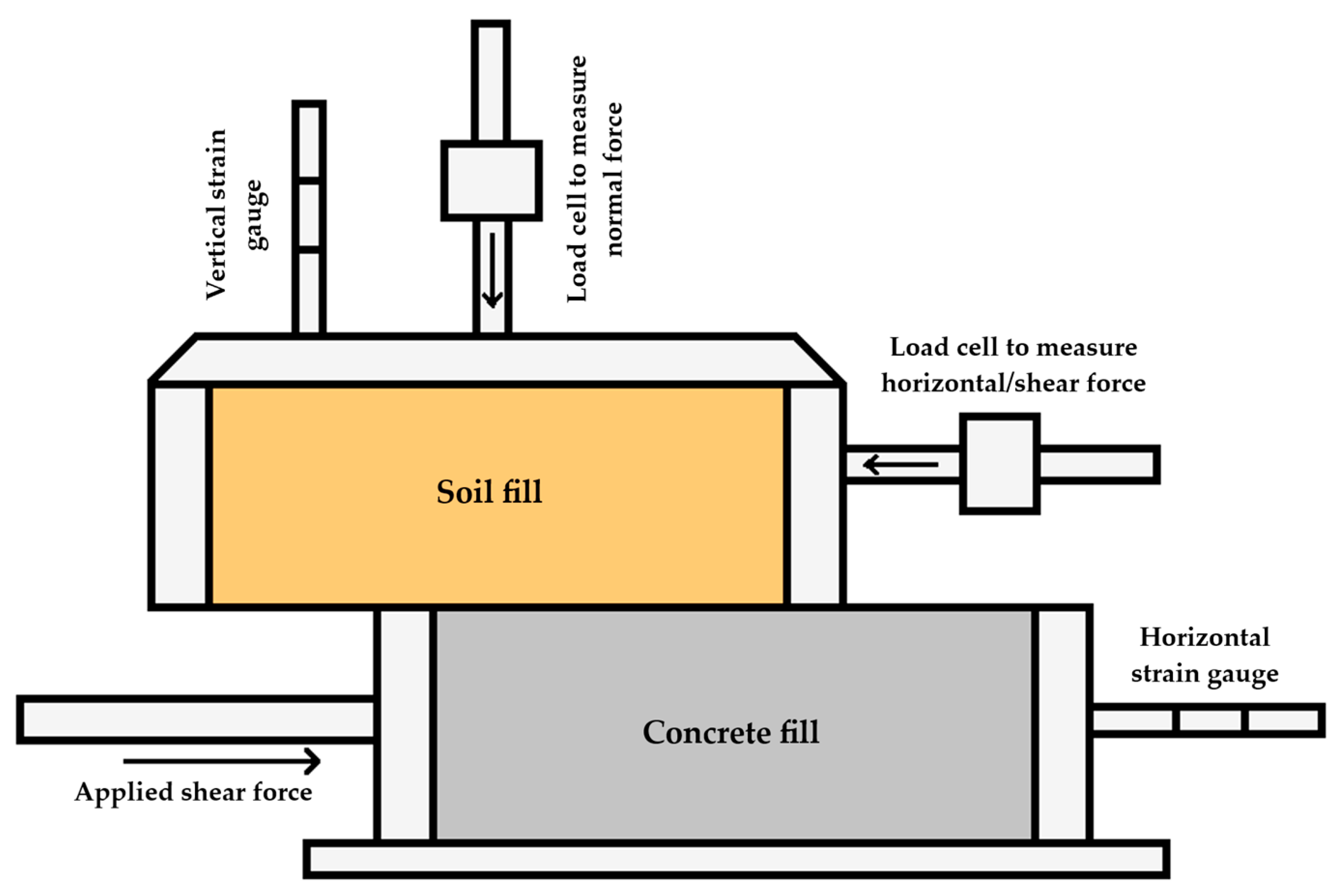
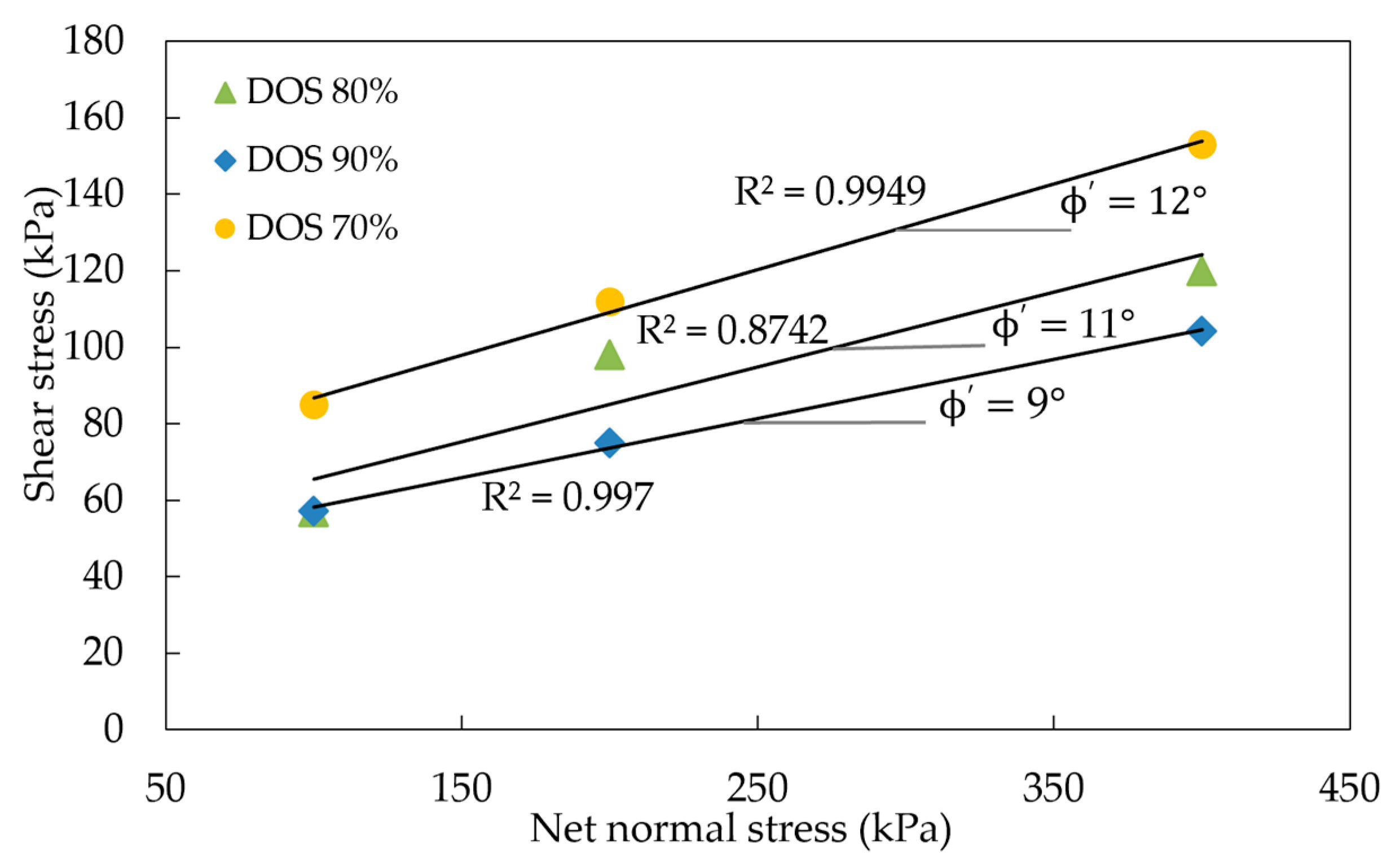
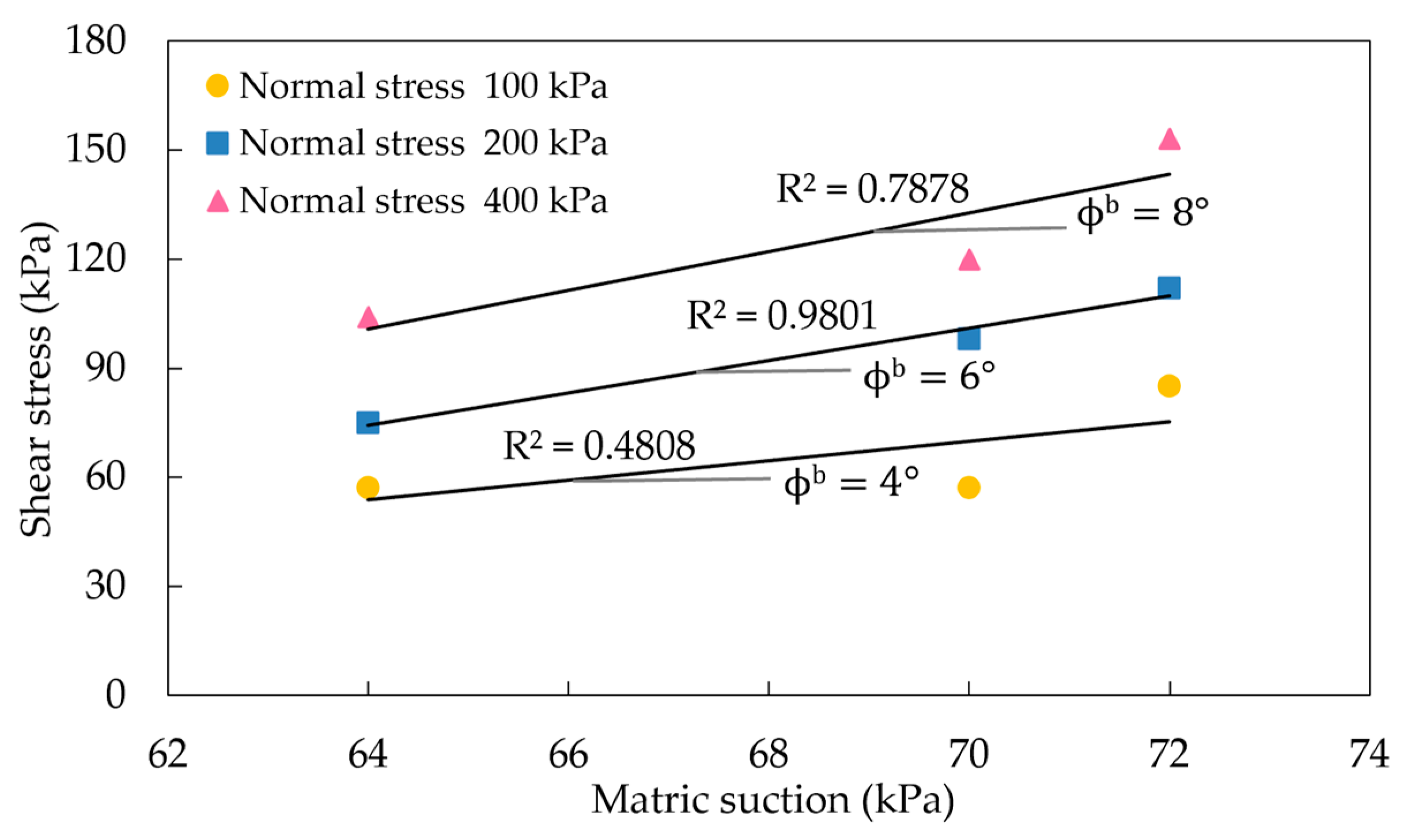
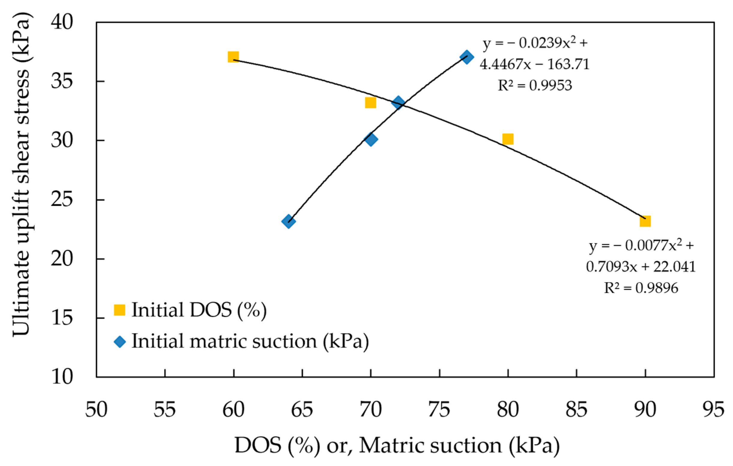
3.4. Direct Shear Tests

The direct shear tests were conducted on soil-concrete specimens prepared in accordance with ASTM D3080 [41] standards. Three soil specimens, each with different initial degrees of saturation, were placed in a 101.3 mm × 101.3 mm × 30 mm mold and compacted in layers using static compaction. Concrete specimens (cement/sand/water ratio = 1:2:0.45) filled the lower half of the direct shear device as shown in Figure 3. The specimens were tested under three net normal stresses (100, 200, and 400 kPa) to determine shear strength parameters (cohesion, C′, and effective friction angle, ϕ′). Soil specimens were consolidated under varying vertical pressures for one day to dissipate excess pore pressure, followed by shearing at 0.0049 mm/min.
Figure 4 shows the relationship between shear stress and net normal stress. As shown in Figure 4, the friction angle (ϕ’) was determined to range from 9° to 12°, indicating no significant variation in friction angles across different initial degrees of saturation, while cohesion varies with matric suction. The coefficient of determination (R2) for the fitted lines was calculated to assess the reliability of the trend. The R2 values shown in Figure 4 range from 0.874 to 0.997, indicating a strong correlation between the measured data and the regression lines. Figure 5 presents the shear stress vs. matric suction for the samples tested. The interface friction angle (ϕb) determined for the samples tested ranges from 4° to 8°, indicating that the interface friction angle (ϕb) increases as the normal stress increases. The R2 values shown in Figure 5 range from 0.481 to 0.980. The R2 value for the 100 kPa case was relatively low, suggesting a weaker correlation under low confining pressure. However, the determined ϕb value is approximately two-thirds of the ϕb value, which is consistent with general findings provided in Fredlund et al. (2012) [20].

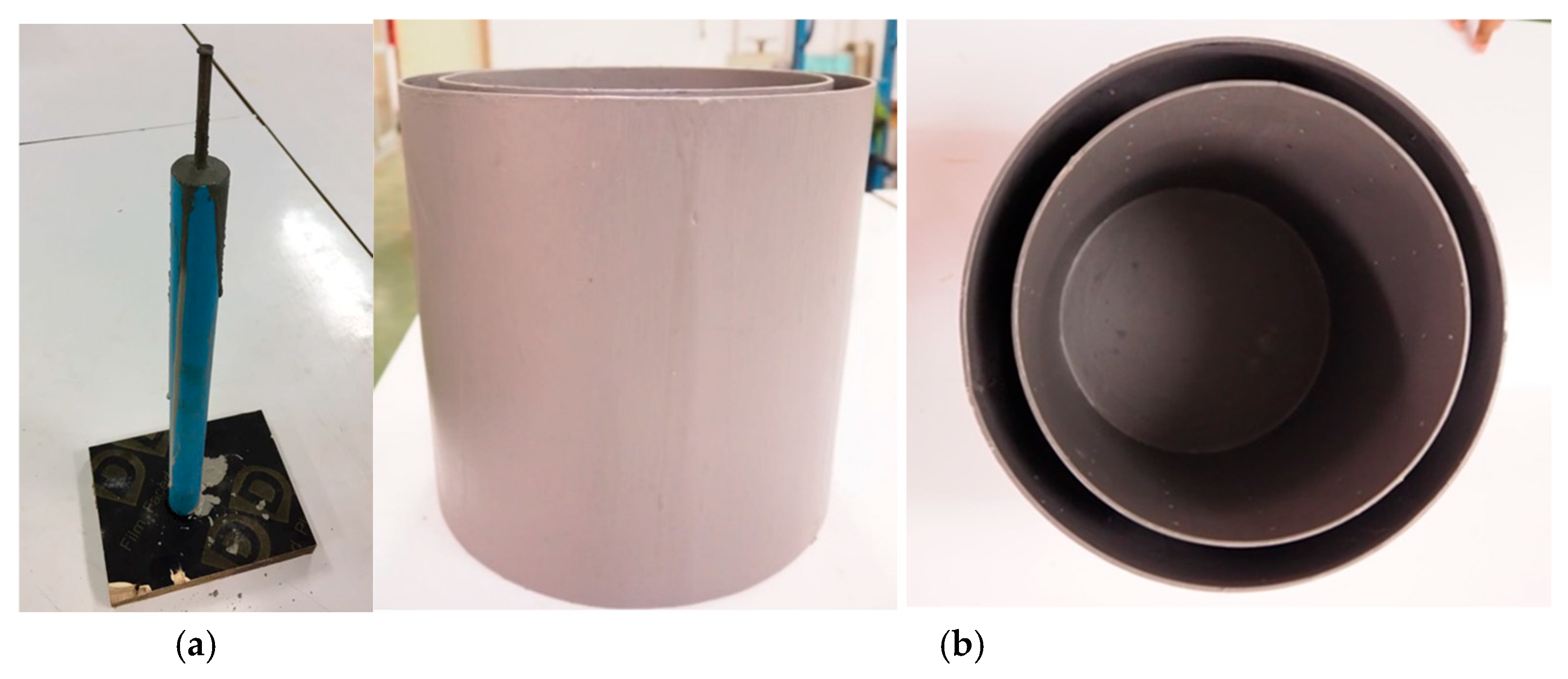
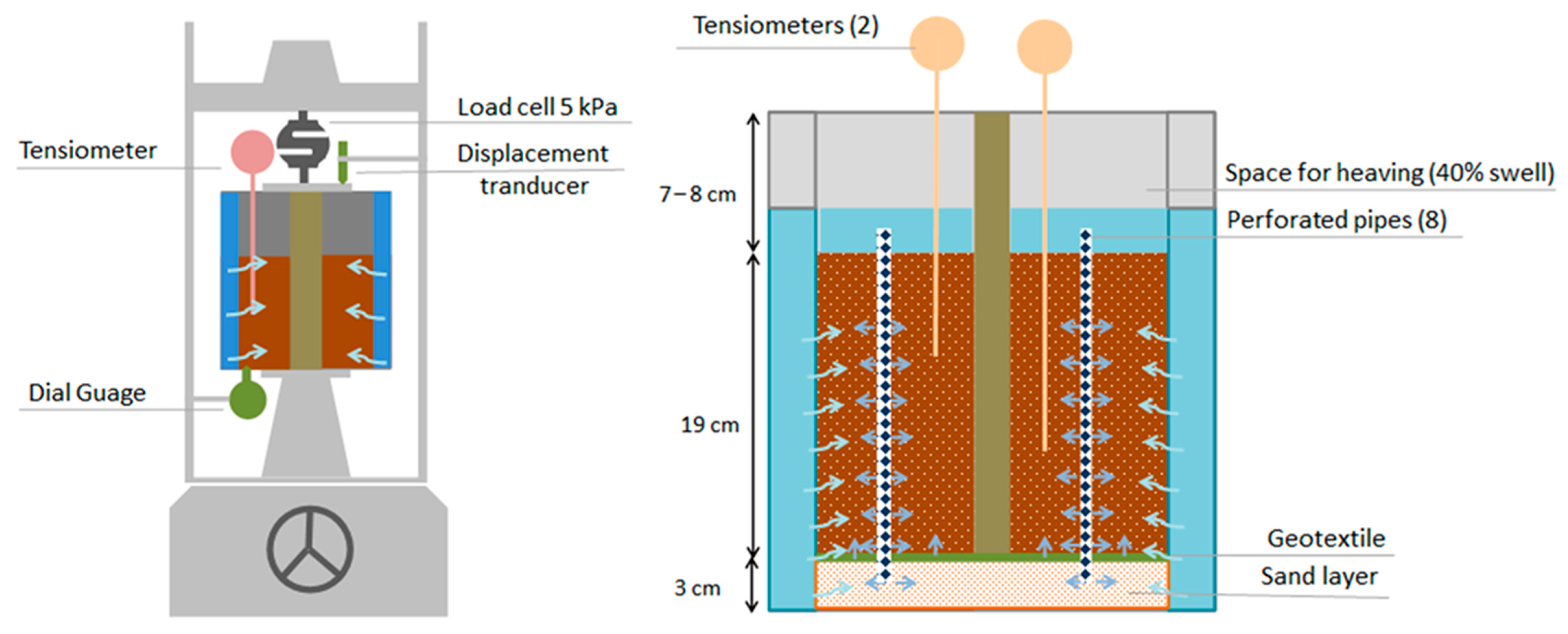
3.5. Pile Uplift Model Tests

A series of laboratory tests were conducted to analyze soil–pile interaction and determine the uplift coefficient under varying saturation levels. Soil samples were prepared at 60%, 70%, 80%, and 90% saturation based on the compaction curve for the direct shear tests. A cement mortar pile model (1:2:0.45 mix, reinforced with RB6) was used, measuring 2.17 cm in diameter and 26 cm in length (refer to Figure 6a).
The pile uplift test was conducted in a modified sphere container (25 cm in diameter × 30 cm in height) with perforations for water infiltration. Perforated pipes facilitated soil saturation, while a sand layer at the bottom, separated by geotextile, allowed infiltration from below. To reduce friction-induced stress loss, the container walls were lubricated with grease (refer to Figure 6b).
The reinforced cement mortar pile was centrally positioned within the mold during compaction, ensuring the pile tip was at the base to eliminate uplift force at the end. The soil samples were placed in six layers, each statically loaded, and stored in a humidity-controlled environment for 24 h to maintain uniform initial water content.
The schematic view of the pile uplift model test is presented in Figure 7. During the testing, the unsaturated soil was gradually wetted via external water infiltration through the center of the container. Tensiometers (Model 2100F) at various depths recorded changes in matric suction. Water infiltration caused soil swelling, generating uplift forces along the pile shaft. Uplift displacement was measured using a transducer, with the load frame’s adjustable screw maintaining the pile’s position. The uplift forces were recorded using a 2 kN load cell at 10 min intervals until stabilization or the estimated maximum was reached. This procedure was repeated for different initial saturation levels, with matric suction measured throughout the test.
Uplift force development was driven by skin friction resistance. As water infiltrated, soil heave increased uplift stress, leading to pile displacement. Initially, the uplift force rose sharply, but as saturation neared completion, the swelling potential was reduced, stabilizing the uplift interface shear stress. The test data indicated that full stabilization took between two and three weeks. Initially, when the soil is not wetted, matric suction dominates downward interface shear stress; however, as the soil is wetted, the swelling pressure becomes the primary contributor to the uplift force. -

4. Evaluation of Pile Uplift Force and Parameters

4.1. Calculation of Pile Uplift Force

The uplift force vs. time was measured throughout the pile uplift tests. The change in uplift force with time was analyzed by fitting the observed data to a hyperbolic model, as described by Equation (13).
U = t a + b t
where U is the uplift force, and “a” and “b” are fitting curve parameters. “t” represents the time since inundation started.
By taking the limit of Equation (13) as “t” approaches infinity, we obtain:
1 U = a t + b
To determine the fitting curve parameters “a” and “b”, a linear graph is conducted using the relationship between 1/U and 1/t. The slope of this linear graph corresponds to the parameter “a” and the intercept represents the parameter “b”. The regression analysis is used to calculate these parameters. The observed data and hyperbolic fitting curve for the initial DOS of 70% are depicted in Figure 8. It is observed in Figure 8 that the majority of the uplift force developed during the early stage of the heaving process.
The results illustrated in Figure 8 are comparable to the findings reported by Chao (2007) [40]. Specifically, Figure 9 presents a similar trend, depicting pile heave data observed at the TRACON site in Denver, Colorado, USA, underlain by expansive soils. In that study, the heave data observed between 2001 and 2006 exhibited a hyperbolic pattern. The response pattern shown in Figure 9 exhibits a strong resemblance to the outcomes of the present study, as illustrated in Figure 8. It should be noted that Figure 8 and Figure 9 represent different physical quantities—uplift force in our experimental model and pile heave measured at the TRACON site. However, the comparison was made to emphasize the similarity in the overall response trend rather than to directly equate the magnitudes or units of the two curves. Both figures show a hyperbolic pattern during the wetting-induced heaving process, where a significant portion of the total response (either uplift force or displacement) develops in the early stages. This trend is critical for understanding the time-dependent behavior of expansive soils and their effect on pile performance.
It is also noteworthy that an increase in swelling pressure, as indicated by Equation (10), results in a corresponding increase in uplift force. As the degree of saturation progresses over time, the swelling pressure intensifies, thereby inducing greater strain or heave, as illustrated in Figure 1. Consequently, although Figure 8 depicts the variation in uplift force with time and Figure 9 represents the heave response, the two remain comparable. This is because the uplift force, driven by the increasing swelling pressure, directly contributes to heave development.
Figure 10 illustrates the relationships between the measured ultimate uplift stress and the initial degree of saturation, as well as the initial matric suction. Figure 10 shows that the ultimate uplift shear stress decreases nonlinearly with increasing initial degree of saturation, but decreases with increasing initial matric suction. It is believed that the observed phenomena are primarily due to the change in the swelling pressures of the specimens at various initial stress state conditions, as presented in Table 4.

4.2. Calculation of α Value

Equation (10) was used to determine the shear stress at the interface between soil and pile in expansive soil. It takes into account the effects of matric suction and swelling pressure. The back-calculation of the α value from unsaturated conditions can be expressed as follows:
α = P F S π d L ( u a f u w f ) tan ϕ θ θ r θ s θ r σ c v v  
The uplift coefficient (α) is a key parameter to compute the pile uplift force in pile design for expansive soils. The back-calculated α values for the samples tested at various degrees of saturation were summarized in Table 4. The back-calculated α values vs. the initial degrees of saturation are plotted in Figure 11. Table 4 and Figure 11 indicate that the average back-calculated α values range from 0.115 to 0.125, and the α value increases as the initial degree of saturation increases. The α value increased by approximately 9% within the degree of saturation values tested.
As discussed in Section 2, the swelling pressure ratio value, β, can be determined as β = α/tan(ϕ′). Figure 12 plots the calculated β values vs. the initial degrees of saturation. In the calculations, the interface friction angle (ϕ′) was assumed to be a constant value of 11 degrees. Figure 12 indicates that the calculated average values range from 0.591 to 0.640, and the β value increases as the initial degree of saturation increases. The β value increased by approximately 8% within the degree of saturation values tested. The results of the β values align with findings by Erol and Ergun (1994) [42]. This is attributed to a greater reduction in vertical swelling pressure than lateral swelling pressure as saturation increases, leading to a higher β value.
For practical design applications, the use of constant α and β values is justified within the tested range. However, further investigation into the effects of pile geometry and soil properties is recommended. Previously, He et al. (2025) [43] investigated the effect of pile length on pile-soil interaction, whereas Asif et al. (2022) [44] also considered factors such as pile diameter, soil type, and group pile orientation. Future research could incorporate all these parameters to study their combined effects on expansive soils.

5. Conclusions and Recommendations

This study investigated the influence of the degree of saturation on the pile uplift force and the α and β parameters for pile foundations in expansive soils. Laboratory tests and theoretical back-calculation methods were conducted to evaluate the relationships among α, matric suction, and swelling pressure. The key findings are summarized as follows:
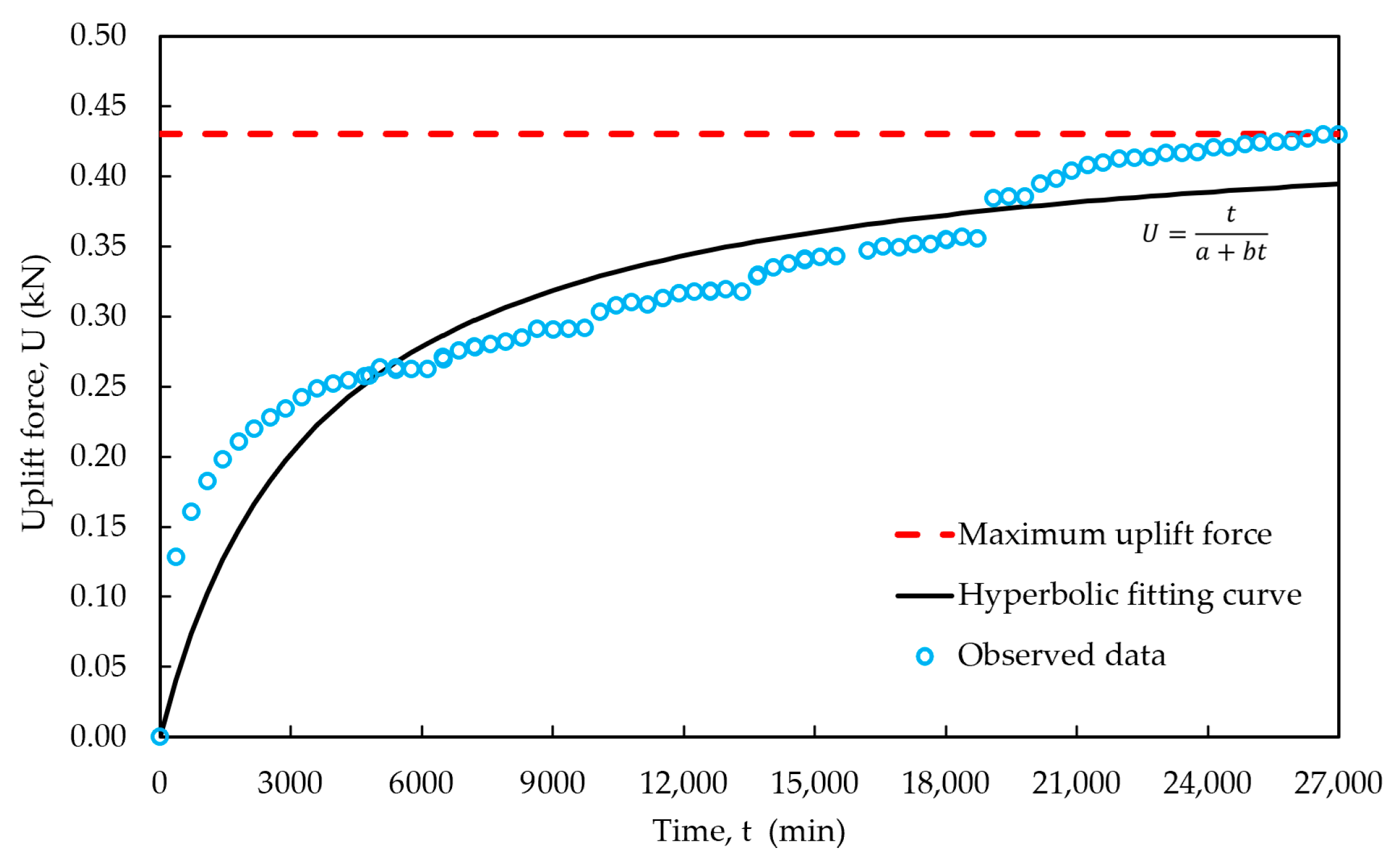
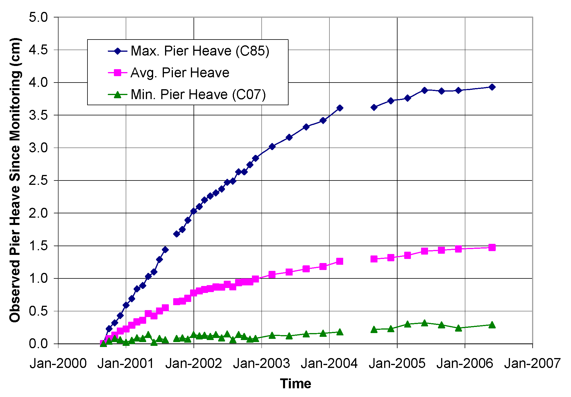
  • The uplift force developed along the pile shaft during the wetting process exhibited a hyperbolic trend. A significant portion of the uplift force is developed during the early stage of the heaving process. This trend is consistent with the pile heave pattern observed at the TRACON site, and aligns with our observation that the majority of the heave, and thus the associated distress to houses, occurred at the beginning of the construction period.
  • The uplift coefficient, α, is a key parameter for computing pile uplift force in pile design for expansive soils. The α value increases as the initial degree of saturation increases, with a change of approximately 9% within the tested saturation range. Based on the experimental investigation, the back-calculated α values were relatively constant across soils with varying initial degrees of saturation, suggesting that a constant α value may be used in design.
  • The α values obtained in this study fall within a typically accepted lower to moderate range but are notably lower than some of the higher values reported in the literature. This indicates potential variability depending on site-specific conditions, and therefore, it is recommended that the uplift coefficient be validated through field-scale investigations.
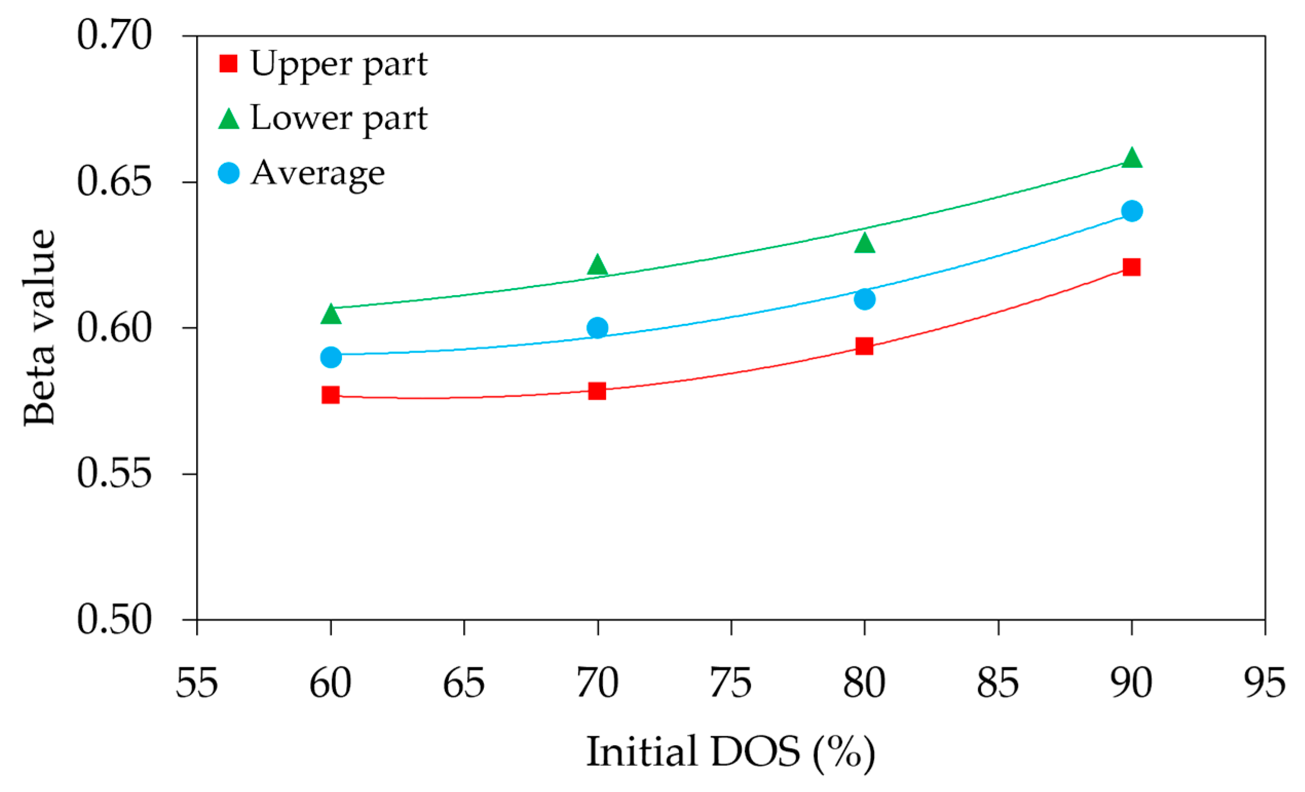
  • The swelling pressure ratio, β, was evaluated to understand the difference between horizontal and vertical swelling pressures. The results indicate that β increases with the initial degree of saturation, with an approximate change of 8% within the tested range. This trend is attributed to a greater reduction in vertical swelling pressure compared to lateral swelling pressure as saturation increases, leading to an overall increase in the β value.
  • For practical design applications, the use of constant α and β values is considered acceptable within the tested range. However, further research is recommended to explore the influence of pile geometry and soil properties in more detail. Previous studies have examined individual factors such as pile length, diameter, soil type, and group pile orientation. Future investigations could benefit from considering these parameters collectively to better understand their combined impact on the behavior of expansive soils. Additionally, it is suggested that the proposed theoretical equation be validated through comparison with field data and other empirical approaches to ensure its accuracy and reliability in real-world engineering practice.

Author Contributions

Conceptualization, K.C.C., A-N.C. and T.H.A.; methodology, K.C.C., A-N.C. and T.H.A.; validation, K.C.C. and T.H.A.; formal analysis, A-N.C. and T.H.A.; investigation, K.C.C. and A-N.C.; resources, K.C.C., A-N.C. and T.H.A.; data curation, A-N.C. and T.H.A.; writing—original draft preparation, A-N.C. and T.H.A.; writing—review and editing, K.C.C.; visualization, T.H.A.; supervision, K.C.C.; project administration, K.C.C.; funding acquisition, K.C.C. All authors have read and agreed to the published version of the manuscript.

Funding

This research received no external funding.

Institutional Review Board Statement

Not applicable.

Informed Consent Statement

Not applicable.

Data Availability Statement

The data used to substantiate the findings of this study are contained within the article.

Conflicts of Interest

The authors declare no conflicts of interest.

References

  1. Mitchell, J.K.; Soga, K. Fundamentals of Soil Behavior; John Wiley & Sons, Inc.: New York, NY, USA, 1993. [Google Scholar]
  2. Muhunthan, B.; Yin, J.H. Behavior of piles in expansive soils: A review. J. Geotech. Geoenviron. Eng. 2003, 129, 207–222. [Google Scholar]
  3. Das, B.M. Principles of Geotechnical Engineering, 7th ed.; Cengage Learning: Stamford, CT, USA, 2006. [Google Scholar]
  4. Soundara, B.; Robinson, R.G. Hyperbolic model to evaluate uplift force on pile in expansive soils. KSCE J. Civ. Eng. 2016, 21, 746–751. [Google Scholar] [CrossRef]
  5. Nelson, J.D.; Chao, K.C.; Overton, D.D.; Nelson, E.J. Foundation Engineering for Expansive Soils; John Wiley & Sons, Inc.: Hoboken, NJ, USA, 2015. [Google Scholar]
  6. Mohan, D.; Chandra, S. Frictional resistance of bored piles in expansive clays. Geotechnique 1961, 11, 294–301. [Google Scholar] [CrossRef]
  7. Johnson, L.D.; Stroman, W.R. Vertical behaviour of two 16-year old drilled shafts in expansive soils. In Analysis and Design of Pile Foundations; ASCE: New York, NY, USA, 1984; pp. 154–173. [Google Scholar]
  8. Nguyen, H.T.; Bui, Q.B.; Bui, D.T.; Tran, V.Q.; Nguyen, T.T.; Pham, B.T. A Hybrid Artificial Intelligence Approach for Predicting the Load-Bearing Capacity of Driven Piles. Can. Geotech. J. 2022, 59, 878–891. [Google Scholar] [CrossRef]
  9. Colorado Association of Geotechnical Engineers (CAGE). Commentary on Geotechnical Practices: Drilled Pier Design Criteria for Lightly Loaded Structures in the Denver Metropolitan Area; Colorado Association of Geotechnical Engineers: Denver, CO, USA, 1999. [Google Scholar]
  10. Poulos, H.G.; Davis, E.H. Pile Foundation Analysis and Design; John Willey and Sons, Inc.: New York, NY, USA, 1980. [Google Scholar]
  11. Nelson, J.D.; Chao, K.C.; Overton, D.D.; Schaut, R.W. Calculation of heave of deep pier foundations. Geotech. Eng. J. SEAGS AGSSEA 2012, 43, 12–25. [Google Scholar] [CrossRef]
  12. Crilly, M.S.; Driscoll, R.M.C. Behaviour of lightly loaded piles in swelling ground and implications for their design. Geotech. Eng. 2000, 143, 3–16. [Google Scholar] [CrossRef]
  13. Chao, K.C.; Nelson, J.D.; Overton, D.D.; Cumbers, J.M. Soil water retention curves for remolded expansive soils. In Proceedings of the 1st European Conference on Unsaturated Soils, Durham, UK, 2–4 July 2008. [Google Scholar]
  14. Nelson, J.; Miller, D.J. Expansive Soils: Problems and Practice in Foundation and Pavement Engineering; John Wiley & Sons: Hoboken, NJ, USA, 1997. [Google Scholar]
  15. Tadepalli, R.T.; Fredlund, D.G. Predicting the shrinkage properties of expansive soils. Can. Geotech. J. 1991, 28, 310–321. [Google Scholar]
  16. Pereira, J.M.; Fredlund, D.G. A review of the shear strength of unsaturated expansive soils. Can. Geotech. J. 2000, 37, 1033–1054. [Google Scholar]
  17. Lim, J.Y.; Miller, G.A. Shear strength characteristics of unsaturated expansive clays. Can. Geotech. J. 2004, 41, 365–378. [Google Scholar]
  18. Noor, I.M.; Faizal, P.; Saleh, M.M.; Ismail, N.; Zakaria, R. Behavior of lateritic expansive soil as foundation material. Electron. J. Geotech. Eng. 2013, 18, 2313–2323. [Google Scholar]
  19. Awadalseed, W.; Zhang, X.; Zhang, D.; Ji, Y.; Bai, Y.; Zhao, H. Estimation of Pile Shaft Friction in Expansive Soil upon Water Infiltration. KSCE J. Civ. Eng. 2024, 28, 4832–4843. [Google Scholar] [CrossRef]
  20. Fredlund, D.G.; Rahardjo, H.; Fredlund, M.D. Unsaturated Soil Mechanics in Engineering Practice; John Willey and Sons, Inc.: New York, NY, USA, 2012. [Google Scholar] [CrossRef]
  21. Hamid, T.B.; Miller, G.A. Shear strength of unsaturated soil interfaces. Can. Geotech. J. 2009, 46, 595–606. [Google Scholar] [CrossRef]
  22. Chao, K.C.; Kang, J.B.; Nelson, J.D. Challenges in water migration modeling for expansive soils. In Proceedings of the Geo-Shanghai Conference, Shanghai, China, 26–28 May 2014. [Google Scholar] [CrossRef]
  23. Chao, K.C.; Nelson, J.D. Validation of Foundation Design Method on Expansive Soils. Geotech. Eng. J. SEAGS AGSSEA 2019, 50, 103–111. [Google Scholar] [CrossRef]
  24. Chao, K.C.; Overton, D.D.; Nelson, J.D. Design and installation of deep benchmarks in expansive soil. J. Surv. Eng. 2006, 132, 124–131. [Google Scholar] [CrossRef]
  25. Nelson, J.D.; Chao, K.C.; Overton, D.D. Design of pier foundations on expansive soils. In Proceedings of the 3rd Asian Conference on Unsaturated Soils, Nanjing, China, 20–24 April 2007. [Google Scholar]
  26. Sapaz, B. Lateral Versus Vertical Swell Pressures in Expansive Soils. Master’s Thesis, Middle East Technical University, Ankara, Turkey, 2004. [Google Scholar]
  27. Katti, R.K.; Katti, D.R.; Katti, A.R. Behaviour of Saturated Expansive Soil and Control Methods, Revised and Enlarged ed.; Balkema: Rotterdam, The Netherlands, 2002. [Google Scholar]
  28. Chen, F.H. Foundations on Expansive Soils; Elsevier Science Publishing Company Inc.: New York, NY, USA, 1988. [Google Scholar]
  29. O’Neill, M.W. Adaptive model for drilled shafts in expansive clay. In Special Topics in Foundations; ASCE: Reston, VA, USA, 1988; pp. 1–20. [Google Scholar]
  30. Benvenga, M.M. Pier-Soil Adhesion Factor for Drilled Shaft Piers in Expansive Soil. Ph.D. Thesis, Colorado State University, Fort Collins, CO, USA, 2005. [Google Scholar]
  31. Huang, L.; Deng, Q.L.; Wang, H.N. Instability Behavior of Loose Granular Material: A New Perspective via DEM. Granul. Matter 2024, 26, 84. [Google Scholar] [CrossRef]
  32. Wu, Z.; Huang, L.; Deng, Q.L. Analysis of Factors Affecting the Shear Characteristics of Granular Soils under Increasing Axial Stress in Biaxial Compression Test via DEM. Comput. Part. Mech. 2025. [Google Scholar] [CrossRef]
  33. ASTM D854-10; Standard Test Methods for Specific Gravity of Soil Solids by Water Pycnometer. ASTM International: West Conshohocken, PA, USA, 2010. [CrossRef]
  34. ASTM D4318-10; Standard Test Methods for Liquid Limit, Plastic Limit, and Plasticity Index of Soils. ASTM International: West Conshohocken, PA, USA, 2010. [CrossRef]
  35. ASTM D698-12; Standard Test Methods for Laboratory Compaction Characteristics of Soil Using Standard Effort. ASTM International: West Conshohocken, PA, USA, 2012. [CrossRef]
  36. Nelson, E.J.; Chao, K.C.; Nelson, J.D.; Overton, D.D. Lessons learned from foundation and slab failures on expansive soils. J. Perform. Constr. Facil. 2017, 31, 3. [Google Scholar] [CrossRef]
  37. Chao, K.C.; Kang, J.B.; Nelson, J.D. Evaluation of failure of embankment slope constructed with expansive soils. Geotech. Eng. J. SEAGS AGSSEA 2018, 49, 2. [Google Scholar] [CrossRef]
  38. Nelson, J.D.; Chao, K.C. Relationship Between Swelling Pressures Determined by Constant Volume and Consolidation-Swell Oedometer Tests. In Proceedings of the Sixth International Conference on Unsaturated Soils, Sydney, Australia, 2–4 July 2014. [Google Scholar] [CrossRef]
  39. Chao, K.C.; Overton, D.D.; Nelson, J.D. The Effects of Site Conditions on the Predicted Time Rate of Heave. In Proceedings of the Unsaturated Soils 2006 Conference, Carefree, AZ, USA, 2–6 April 2006. [Google Scholar] [CrossRef]
  40. Chao, K.C. Design Principles for Foundations on Expansive Soils. Ph.D. Dissertation, Colorado State University, Fort Collins, CO, USA, 2007. [Google Scholar]
  41. ASTM D3080-11; Standard Test Method for Direct Shear Test of Soils Under Consolidated Drained Conditions. ASTM International: West Conshohocken, PA, USA, 2011.
  42. Erol, O.; Ergun, U. Lateral swell pressure in expansive soils. In Proceedings of the 8th International Conference on Soil Mechanics and Foundations Engineering, New Delhi, India, 4–10 January 1994; pp. 1511–1514. [Google Scholar]
  43. He, D.; Cheng, Y.; Liu, H.; Lin, H. Pile–Soil Interaction and Group Pile Effect in Composite Foundation Under Different Pile Length Conditions. Buildings 2025, 15, 1248. [Google Scholar] [CrossRef]
  44. Asif, T.H.; Islam, S.; Basak, A.; Shahriar, F.; Rahman, S.M. Application of Numerical Method in Assessing the Variations in Pile Group Efficiency under Different Circumstances. Comput. Eng. Phys. Model. 2022, 5, 50–68. [Google Scholar] [CrossRef]
Figure 1. Typical CS and CV test results reproduced with permission from Nelson, J.D. et al., Foundation Engineering for Expansive Soils; published by John Wiley & Sons, Inc., 2015 [5].
Applsci 15 07102 g001
Figure 2. Relationship of normalized swelling percentage and degree of saturation, reproduced with permission from Chao, K.C., Design Principles for Foundations on Expansive Soils; Ph.D. Dissertation, Colorado State University, 2007 [40].
Applsci 15 07102 g002
Figure 3. Schematic diagram of the direct shear test.
Applsci 15 07102 g003
Figure 4. Variation in shear strength with the net normal stress under different DOS.
Applsci 15 07102 g004
Figure 5. Variation in shear strength with matric suction under different net normal stress.
Applsci 15 07102 g005
Figure 6. Pile test model and container used in the model. (a) Pile uplift model. (b) Container used.
Applsci 15 07102 g006
Figure 7. Schematic view of the pile uplift model test for determining the interface shear stress.
Applsci 15 07102 g007
Figure 8. Comparison between the observed data and the hyperbolic fitting curve of the soil sample at the initial DOS of 70%.
Applsci 15 07102 g008
Figure 9. Pile heave pattern at the TRACON site, Denver, Colorado, USA, reproduced with permission from Chao, K.C., Design Principles for Foundations on Expansive Soils; Ph.D. Dissertation, Colorado State University, 2007 [40].
Applsci 15 07102 g009
Figure 10. Ultimate uplift shear stress versus the initial degree of saturation and initial degree of saturation.
Applsci 15 07102 g010
Figure 11. Relationship between the α value and initial degree of saturation.4.3. Calculation of β Value.
Applsci 15 07102 g011
Figure 12. Variation in β value with increasing initial degree of saturation.
Applsci 15 07102 g012
Table 1. Physical properties of Expansive soil.
No.TestStandardsValue/Description
1Soil-Artificial Clay
(sand: sodium bentonite = 45:55)
2Specific Gravity (Gs)ASTM
D854-10 [33]
2.61
3Liquid Limit (%)ASTM
D4318-10 [34]
315
4Plastic Limit (%)47
5Plastic Index (%)268
6Grain Size DistributionUSCS-
% Gravel0
%Coarse Sand3.2
%Medium Sand27.2
% Fine Sand14
%Silt and clay55.6
7Soil ClassificationUSCSCH
8Color-Brown
9Maximum Dry Density
(kN/m3)
ASTM
D698-12 [35]
14.95
10Optimum Water Content (%)ASTM
D698-12 [35]
24
Table 2. Soil specimen properties at different degrees of saturation.
Degree of Saturation
(%)
Dry Unit Weight (kN/m3)Water Content (%)Total Unit Weight (kN/m3)
6014.2018.4516.82
7014.2021.5317.26
8014.2024.6117.70
9014.2027.6818.13
10014.2030.7618.57
Table 3. Oedometer test results of soil specimens with various initial degrees of saturation.
Initial Degree of Saturation, DOS (%)Consolidation Swell Pressure at Full Saturation, σ c s
(kPa)
Constant Volume Swell Pressure at Full Saturation, σ c v
(kPa)
60830260
70770251
80710240
90650231
Table 4. Soil specimen properties from pile uplift model test.
DescriptionSymbols and UnitsUpper
Part
Lower
Part
Upper
Part
Lower
Part
Upper
Part
Lower
Part
Upper
Part
Lower
Part
Initial conditionsDOS %6060707080809090
Suction7777727270706464
(kPa) (1)
w%18.518.521.521.524.624.627.727.7
ϴ%26.826.831.231.235.735.740.140.1
Partially wetted conditionsDOS %9691979198939795
Suction (kPa)4660306026573252
w%29.52829.82830.128.629.829.2
ϴ%42.840.643.240.643.741.543.242.3
ε%sn(2)0.980.920.940.780.940.750.680.49
( σ c v )v (3)254225245187218162142106
γ total18.418.218.418.218.518.318.418.4
PFS0.480.480.430.430.390.390.30.3
Sat/Unsatϕ(4)1111111111111111
C(5) 656546464242
α0.1120.1180.1120.1210.1150.1220.1210.128
Average α0.1150.1170.1190.124
Notes: (1) (uauw), matric suction from tensiometer measurement. (2) ε%sn, obtained from Figure 2. (3) ( σ c v )v, determined using the approach outlined in Chao (2007) [40]. (4),(5) ϕ’ and C’, obtained from the consolidated drain-direct shear test.
Disclaimer/Publisher’s Note: The statements, opinions and data contained in all publications are solely those of the individual author(s) and contributor(s) and not of MDPI and/or the editor(s). MDPI and/or the editor(s) disclaim responsibility for any injury to people or property resulting from any ideas, methods, instructions or products referred to in the content.

