Study on Calibration Method of Micromechanical Parameters for Discrete Element Model of Moderately Consolidated Sandstones

Abstract
1. Introduction
2. Model Establishment and Parameter Selection
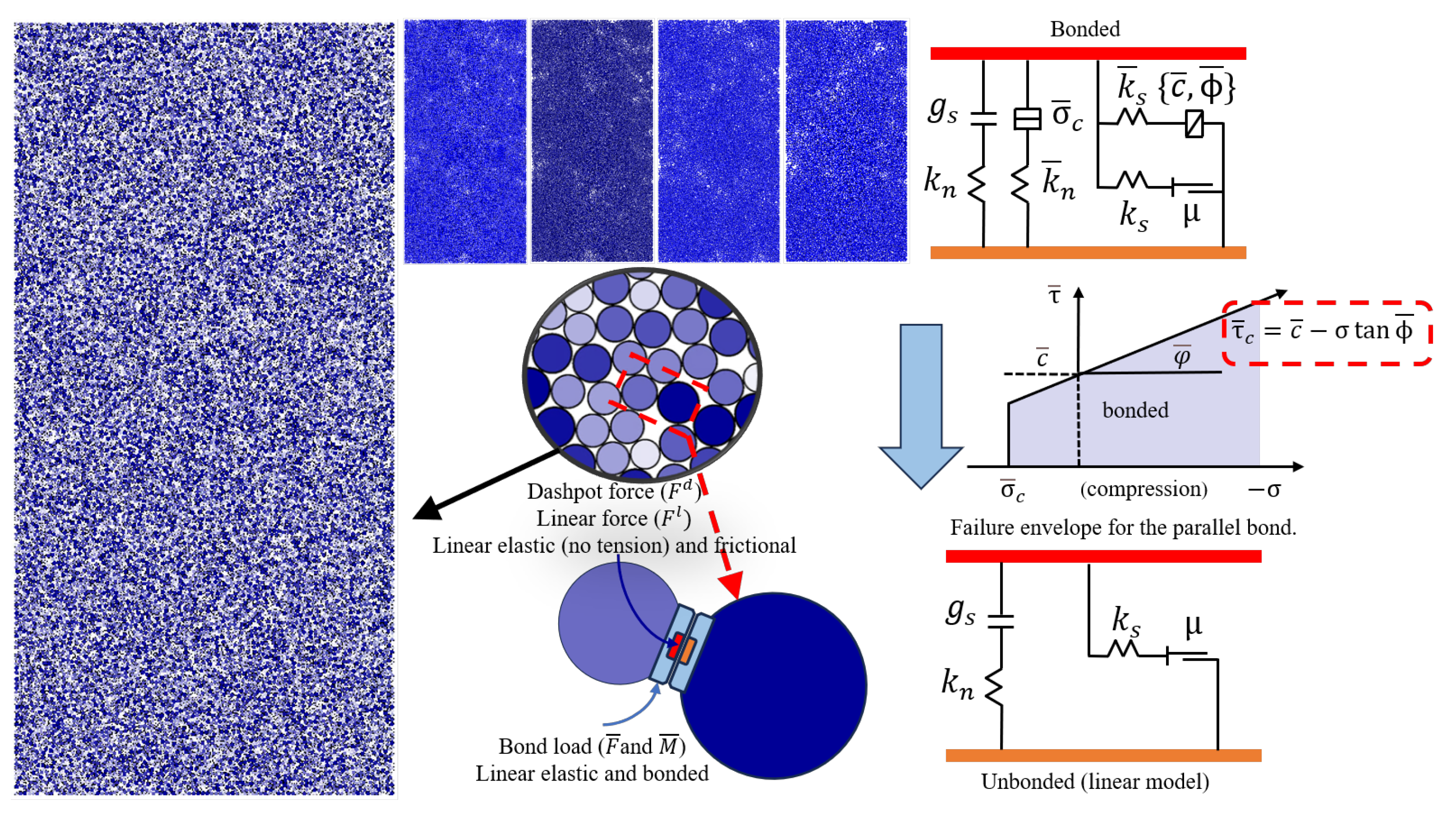
2.1. Model Composition and Main Principles
2.2. Main Parameters of the Model
3. Mechanisms of Macro- and Micro-Parameter Influence and Construction of Multiple Regression Models
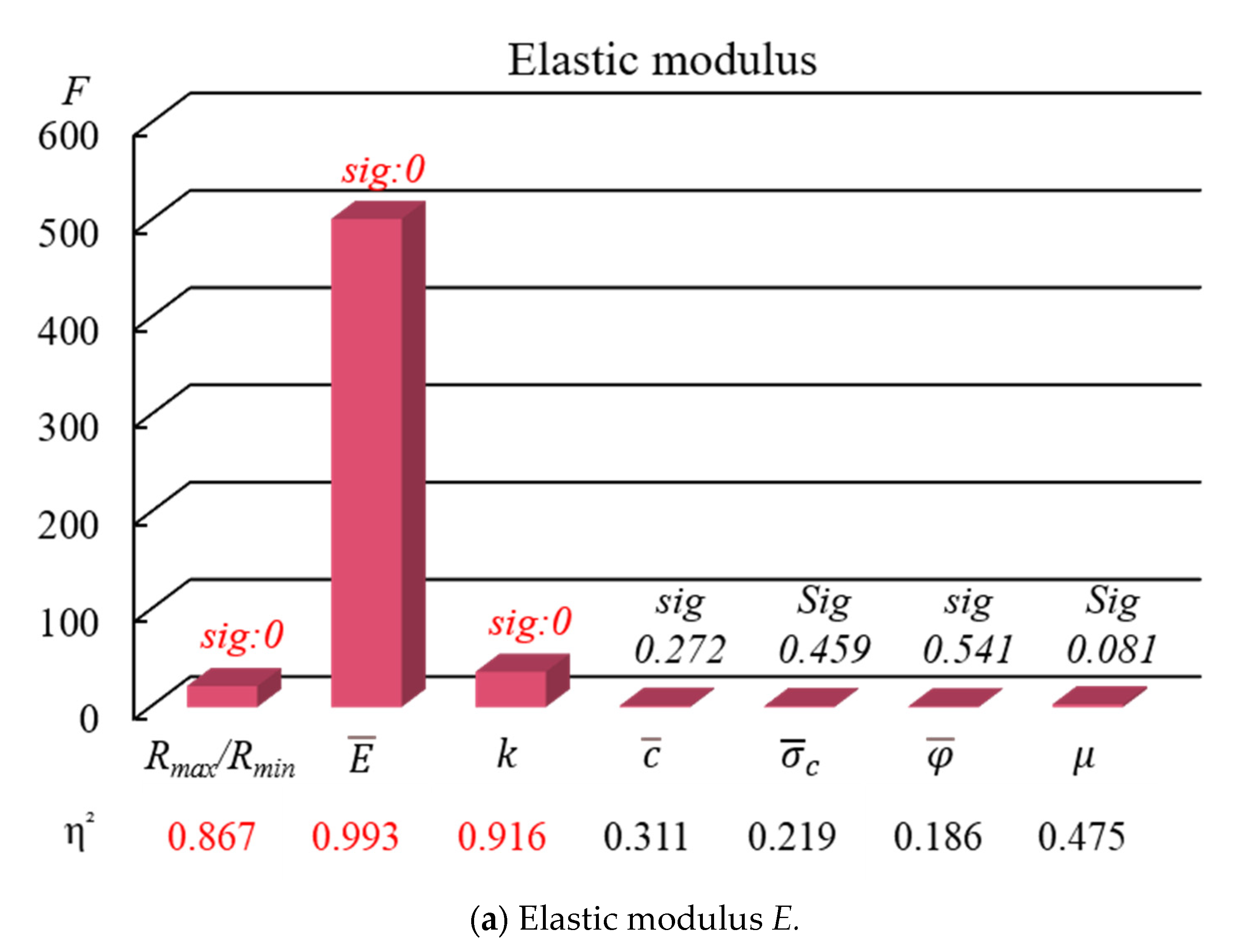
3.1. Analysis of Major Influencing Factors on Macroscopic Mechanical Properties
3.2. Analysis of the Influence Mechanism of Significant Micromechanical Parameters Interaction
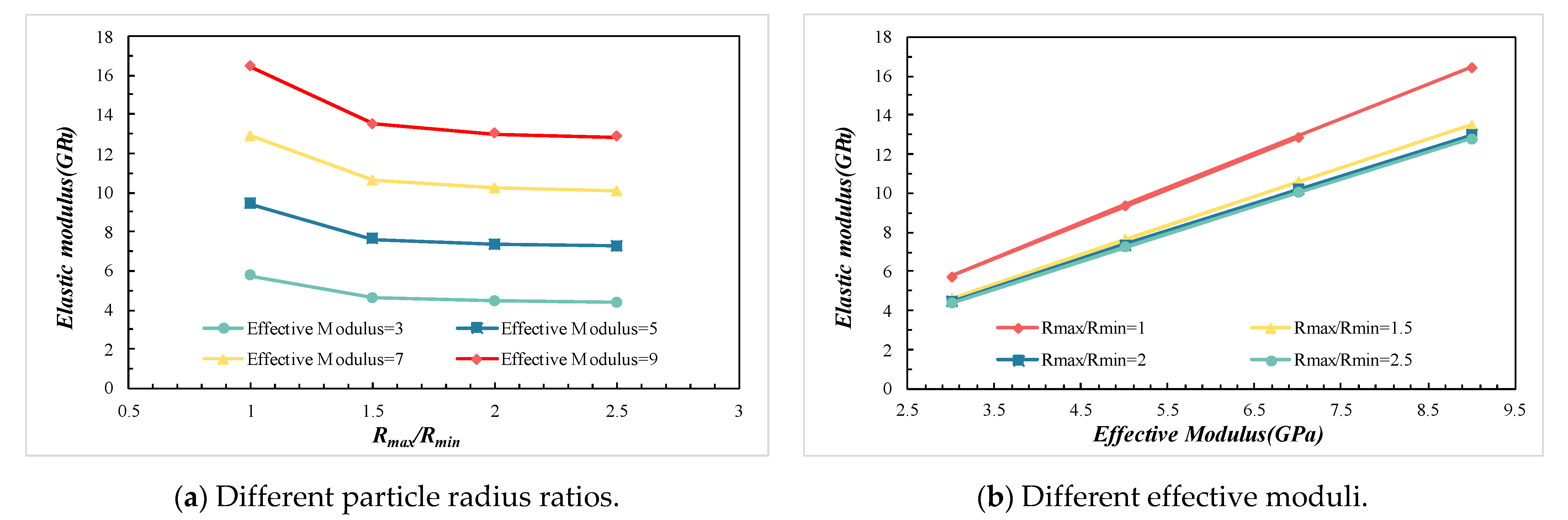
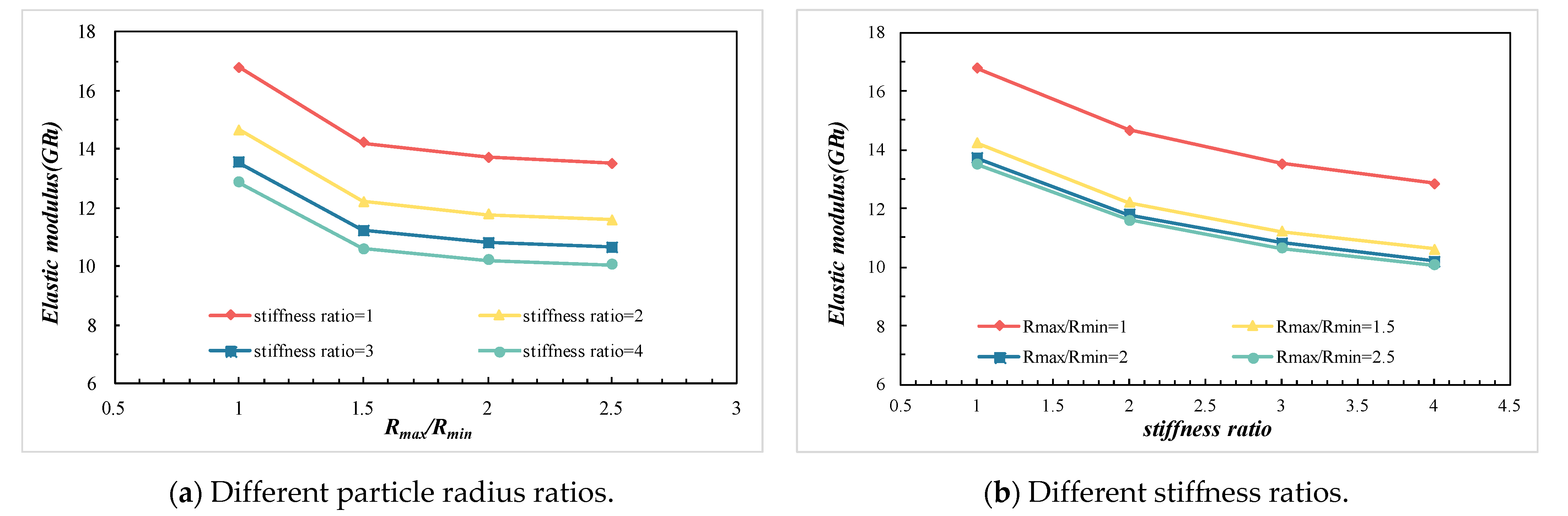
3.2.1. The Effects of Rmax/Rmin, , and k on the E
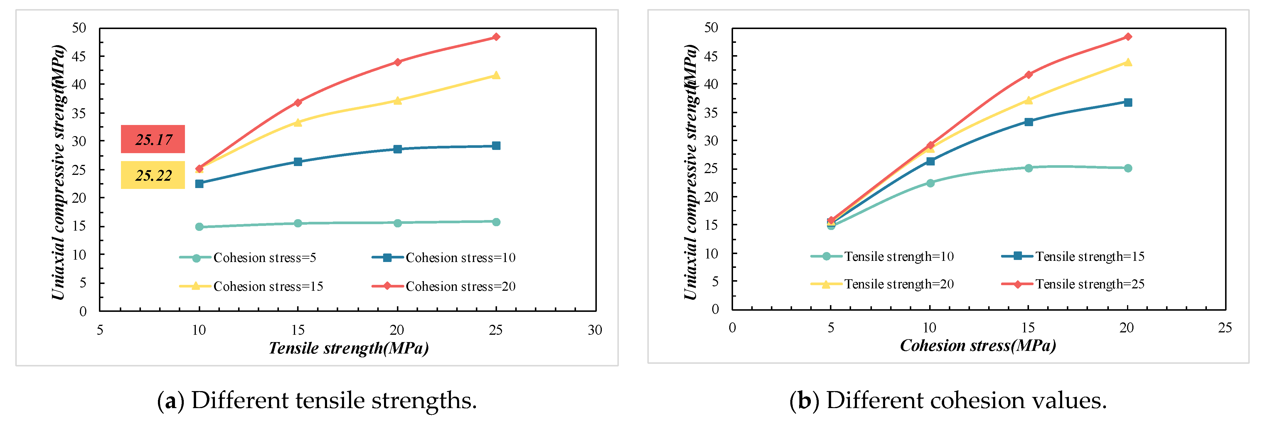
3.2.2. The Effects of and on the UCS
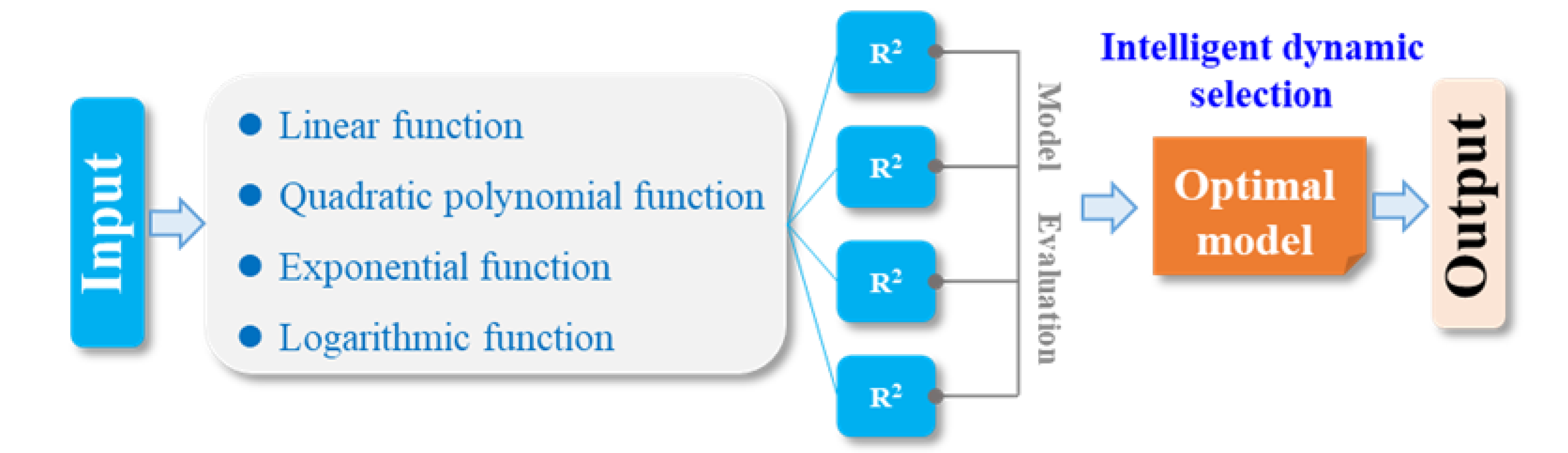
3.3. Regression Analysis of Macroscopic and Micromechanical Parameters Based on an Intelligent Dynamic Regression Selection Mechanism
4. Calibration Method for Micromechanical Parameters of Discrete Element Model and Case Application
4.1. Calibration Method for Micromechanical Parameters of Discrete Element Model
- The uniaxial compressive strength, elastic modulus, and Poisson’s ratio of the rock were determined through uniaxial compression tests. A numerical model was established based on the actual dimensions, porosity, and density of the rock.
- Based on the research rules mentioned above and by comprehensively considering computational performance and simulation accuracy, an appropriate radius ratio was selected to determine the number and spatial distribution of particles in the model.
- The experimentally determined Poisson’s ratio is substituted into Equation (13) to obtain the stiffness ratio , which is then set as . After Rmax/Rmin and are determined, the actual elastic modulus is substituted into Equation (2) to calculate the micromechanical parameter, the effective modulus , which is then set as =
- The failure modes of rock under uniaxial compression include shear failure, tensile failure, and conjugate failure. According to the findings of Wu [27], the ratio of tensile strength to cohesion determines the failure mode of the rock. Specifically, when < 1.66, the rock exhibits tensile failure; when 1.66 < < 3.0, the rock displays conjugate failure; and when > 3.0, the rock undergoes shear failure. Based on the crack morphology observed in the actual rock mechanics test, the corresponding value of is selected. The experimentally measured uniaxial compressive strength (UCS) and the selected are then substituted into Equation (7) to calculate the micromechanical parameters: tensile strength and cohesion .
- Since the friction coefficient () and friction angle () have negligible effects on macroscopic mechanical properties, initial values of and are adopted based on previous research experience [28]. The above micromechanical parameters are incorporated into the parallel-bond model to establish a particle flow model for moderately consolidated sandstone. By comparing the results of laboratory tests and numerical simulations, if the error is less than or equal to 10%, the calibration of the model’s micromechanical parameters is completed. If the error is greater than or equal to 10%, iterative calibration is performed according to Formula (14).
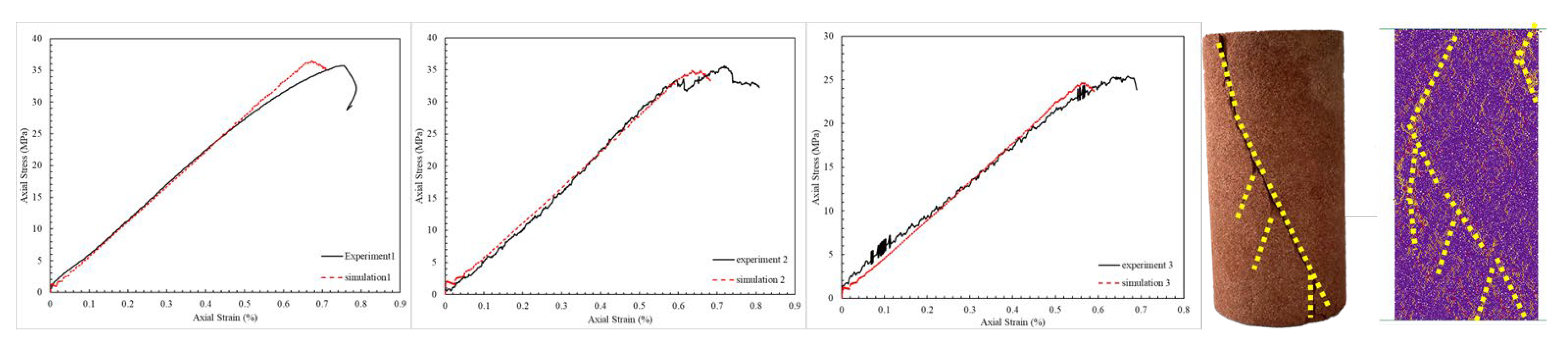
4.2. Case Verification of Moderately Consolidated Sandstone
5. Conclusions
- The primary micromechanical parameters influencing the macroscopic mechanical properties are the maximum-to-minimum particle size ratio, effective modulus, stiffness ratio, tensile strength, and cohesion. The elastic modulus is mainly determined by the effective modulus, stiffness ratio, and particle size ratio. The uniaxial compressive strength depends on cohesion and tensile strength. Poisson’s ratio is most significantly affected by the stiffness ratio alone.
- Interaction analysis shows that the elastic modulus increases with effective modulus and decreases with stiffness ratio. The effect of the particle size ratio on the elastic modulus exhibits a threshold. When the ratio exceeds 2.0, the elastic modulus is mainly controlled by the effective modulus and stiffness ratio. Uniaxial compressive strength increases with both tensile strength and cohesion, with a pronounced synergistic effect when both parameters are high.
- A multivariate predictive model was developed using an intelligent dynamic regression selection mechanism, achieving a goodness of fit above 90%. An iterative correction method for micromechanical parameter calibration was introduced and validated through three sets of laboratory and numerical simulation tests. The resulting macroscopic mechanical parameters show errors within 10% compared with the experimental results, and the fracture morphology of the numerically simulated rock samples is similar to that of the actual cores. These findings confirm that the proposed calibration method is both accurate and efficient.
Author Contributions
Funding
Data Availability Statement
Conflicts of Interest
References
- Naderloo, M.; Ramesh Kumar, K.; Hernandez, E.; Hajibeygi, H.; Barnhoorn, A. Experimental and Numerical Investigation of Sandstone Deformation under Cycling Loading Relevant for Underground Energy Storage. J. Energy Storage 2023, 64, 107198. [Google Scholar] [CrossRef]
- Bo, Z.; Boon, M.; Hajibeygi, H.; Hurter, S. Impact of Experimentally Measured Relative Permeability Hysteresis on Reservoir-Scale Performance of Underground Hydrogen Storage (UHS). Int. J. Hydrogen Energy 2023, 48, 13527–13542. [Google Scholar] [CrossRef]
- Liu, W.; Yan, X.J.; Lin, H. Experimental Investigation of Sand Production in Moderately Consolidated Sandstones. Pet. Sci. Bull. 2021, 6, 67–78. [Google Scholar] [CrossRef]
- Zhou, B. Research of Sand Production Mechanism and Prediction Method of Medium-Consolidated Sandstone Reservoir. Master’s Thesis, China University of Petroleum (Beijing), Beijing, China, 2022. [Google Scholar]
- Haeri, H.; Sarfarazi, V.; Zhu, Z.; Moosavi, E. Effect of Transversely Bedding Layer on the Biaxial Failure Mechanism of Brittle Materials. Struct. Eng. Mech. 2019, 69, 11–20. [Google Scholar]
- Hashemi, S.S.; Momeni, A.A.; Melkoumian, N. Investigation of Borehole Stability in Poorly Cemented Granular Formations by Discrete Element Method. J. Pet. Sci. Eng. 2014, 113, 23–35. [Google Scholar]
- Hadi, M.M.; Kulatilake, P.H.S.W.; Ma, X.; Manchao, H. Development of New Three-Dimensional Rock Mass Strength Criteria. Rock Mech. Rock Eng. 2018, 51, 3537–3561. [Google Scholar]
- Shemirani, A.B.; Haeri, H.; Sarfarazi, V.; Akbarpour, A.; Babanouri, N. The Discrete Element Method Simulation and Experimental Study of Determining the Mode I Stress-Intensity Factor. Struct. Eng. Mech. 2018, 66, 379–386. [Google Scholar]
- Ajamzadeh, M.R.; Sarfarazi, V.; Haeri, H.; Dehghani, H. The Effect of Micro Parameters of PFC Software on the Model Calibration. Smart Struct. Syst. 2018, 22, 643–662. [Google Scholar]
- Bahaaddini, M.; Sharrock, G.; Hebblewhite, B.K. Numerical Direct Shear Tests to Model the Shear Behaviour of Rock Joints. Comput. Geotech. 2013, 51, 101–115. [Google Scholar] [CrossRef]
- Chen, P.Y.; Kong, Y.; Yu, H.M. Research on the Calibration Method of Microparameters of a Uniaxial CompressionPFC2D Model for Rock. Chin. J. Undergr. Space Eng. 2018, 14, 1240–1249. [Google Scholar]
- Zhang, B.Y.; Zhang, C.S.; Wang, C.L.; Hao, B.Q. Calibration Method of Meso-Parameters of PFC2D Flat-Joint Mode. Chin. J. Comput. Mech. 2021, 38, 665–673. [Google Scholar] [CrossRef]
- Jiang, Y.; Zou, W.D. A Study on the Correlation of Macro and Microstructural Parameters of Hollow Cylindrical Grey Sandstone based onPFC3D. Coal Sci. Technol. 2024, 52, 78–89. [Google Scholar] [CrossRef]
- Wang, X.J.; Yang, H.X. Discrete Element Fracture Parameter Prediction of Ballast Particles Based on GA-BPNeural Network Model. J. Southwest Jiaotong Univ. 2024, 59, 1–12. [Google Scholar] [CrossRef]
- Zhong, W.L.; Ding, H.; Fan, L.F. Research on Mesoscopic ParametersCalibration of Geopolymer Concrete Upon BP Neural Network. Eng. Mech. 2023, 5, 1–10. [Google Scholar] [CrossRef]
- Miao, L.L.; Liu, X.R.; Fu, Y.; Zhou, X.H.; Guo, X.Y. The Calibration Method for Microscopic Parameters in the Particle Flow Code Model of Rock-like Materials: A Semi-Analytical Lookup Table Approach. Chin. J. Geotech. Eng. 2024, 47, 1259–1269. [Google Scholar] [CrossRef]
- Abierdi; Zheng, Y.R.; Feng, X.T.; Cong, Y. Relationship Between Particle Micro and Macro Mechanical Parameters of Parallel-Bond Model. Rock Soil Mech. 2018, 39, 1289–1301. [Google Scholar] [CrossRef]
- Xu, Z.H.; Wang, W.; Lin, P.; Xiong, Y.; Liu, Z.Y.; He, S.J. A Parameter Calibration Method for PFC Simulation: Development and a Case Study of Limestone. Geomech. Eng. 2020, 22, 91–108. [Google Scholar] [CrossRef]
- Cundall, P.A.; Strack, O.D.L. A Discrete Numerical Model for Granular Assemblies. Géotechnique 1980, 30, 331–336. [Google Scholar] [CrossRef]
- Kwok, C.Y.; Bolton, M.D. DEM Simulations of Thermally Activated Creep in Soils. Géotechnique 2010, 60, 425–433. [Google Scholar] [CrossRef]
- Jafri, T.; Yoo, H. REV Application in DEM Analysis of Non-Vibrational Rock Splitting Method to Propose Feasible Borehole Spacing. Appl. Ences 2018, 8, 335. [Google Scholar] [CrossRef]
- Itasca Consulting Group, Inc. PFC2D Users Manual (Version 5.0). Minneapolis; Itasca Consulting Group, Inc.: Minneapolis, MN, USA, 2016. [Google Scholar]
- Silva, V.R.S.D.; Ranjith, P.G. A Study of Rock Joint Influence on Rock Fracturing Using a Static Fracture Stimulation Method. J. Mech. Phys. Solids 2020, 137, 103817.1–103817.21. [Google Scholar] [CrossRef]
- Shi, C.; Zhang, Q.; Wang, S.N. Numerical Simulation Technology of Particle Flow (PFC5.0) and Its Application. Rock Soil Mech. 2018, 39 (Suppl. S2), 36. [Google Scholar]
- Bock, S.; Prusek, S. Numerical Study of Pressure on Dams in a Backfilled Mining Shaft Based on PFC3D Code. Comput. Geotech. 2015, 66, 230–244. [Google Scholar] [CrossRef]
- Potyondy, D.O.; Cundall, P.A. A Bonded-Particle Model for Rock. Int. J. Rock Mech. Min. Sci. 2004, 41, 1329–1364. [Google Scholar] [CrossRef]
- Wu, L.Y.; Zhu, Y.H.; Bai, H.B.; Feng, Y.; Li, H.; Su, C.D. Study on theCorrelation of Macro and Meso Parameters of Parallel Bond ModelSandstone. J. Min. Sci. Technol. 2023, 8, 487–501. [Google Scholar] [CrossRef]
- Zhou, J.; Wang, Y.X.; Zhou, Y.F. Macro-Micro Evolution Mechanism on Sandstone Failure in Triaxial Compression Test Based on PFC2D. J. China Coal Soc. 2017, 42 (Suppl. S1), 76–82. [Google Scholar] [CrossRef]


| Parameter Levels | Rmax/Rmin | (GPa) | (MPa) | (MPa) | (°) | ||
|---|---|---|---|---|---|---|---|
| 1 | 1 | 3 | 1 | 5 | 10 | 15 | 0.3 |
| 2 | 1.5 | 5 | 2 | 10 | 15 | 30 | 0.4 |
| 3 | 2 | 7 | 3 | 15 | 20 | 45 | 0.5 |
| 4 | 2.5 | 9 | 4 | 20 | 25 | 60 | 0.6 |
| Number | Rmax/Rmin | (GPa) | (MPa) | (MPa) | (°) | UCS (MPa) | E (GPa) | |||
|---|---|---|---|---|---|---|---|---|---|---|
| 1 | 1 | 7 | 3 | 5 | 20 | 15 | 0.5 | 17.57 | 12.89 | 0.273 |
| 2 | 2 | 5 | 3 | 5 | 15 | 60 | 0.3 | 12.69 | 7.71 | 0.292 |
| 3 | 1.5 | 9 | 3 | 10 | 10 | 15 | 0.4 | 24.8 | 14.10 | 0.303 |
| 4 | 1.5 | 3 | 2 | 5 | 15 | 30 | 0.4 | 14.9 | 5.29 | 0.224 |
| 5 | 1.5 | 7 | 4 | 15 | 10 | 60 | 0.5 | 25.76 | 10.58 | 0.346 |
| 6 | 2 | 3 | 4 | 20 | 15 | 15 | 0.6 | 35.64 | 4.47 | 0.35 |
| 7 | 2 | 9 | 1 | 15 | 10 | 30 | 0.6 | 31.57 | 17.47 | 0.066 |
| 8 | 2.5 | 3 | 3 | 10 | 25 | 60 | 0.6 | 26.28 | 4.68 | 0.294 |
| 9 | 1.5 | 7 | 4 | 5 | 25 | 30 | 0.6 | 18.57 | 10.60 | 0.336 |
| 10 | 2.5 | 7 | 1 | 10 | 15 | 60 | 0.4 | 26.06 | 13.29 | 0.086 |
| 11 | 2.5 | 9 | 2 | 15 | 15 | 15 | 0.5 | 36.38 | 14.75 | 0.224 |
| 12 | 1 | 3 | 1 | 5 | 10 | 15 | 0.3 | 10.57 | 7.17 | 0.093 |
| 13 | 2.5 | 5 | 4 | 5 | 10 | 45 | 0.4 | 14.81 | 7.19 | 0.332 |
| 14 | 2 | 9 | 1 | 5 | 25 | 60 | 0.5 | 14.97 | 16.97 | 0.06 |
| 15 | 1 | 3 | 1 | 15 | 25 | 45 | 0.4 | 35.54 | 7.47 | 0.099 |
| 16 | 2.5 | 7 | 1 | 20 | 20 | 30 | 0.3 | 42.99 | 13.20 | 0.107 |
| 17 | 1 | 9 | 4 | 10 | 15 | 30 | 0.3 | 26.93 | 16.03 | 0.337 |
| 18 | 1 | 9 | 4 | 20 | 20 | 60 | 0.4 | 44.33 | 16.47 | 0.348 |
| 19 | 1.5 | 9 | 3 | 20 | 25 | 45 | 0.3 | 52.35 | 14.04 | 0.329 |
| 20 | 2.5 | 3 | 3 | 20 | 10 | 30 | 0.5 | 25.21 | 4.64 | 0.299 |
| 21 | 1 | 5 | 2 | 10 | 25 | 30 | 0.5 | 27.54 | 10.71 | 0.220 |
| 22 | 1.5 | 5 | 1 | 10 | 20 | 15 | 0.6 | 25.38 | 11.89 | 0.245 |
| 23 | 2 | 7 | 2 | 10 | 10 | 45 | 0.3 | 24.03 | 11.44 | 0.238 |
| 24 | 2.5 | 5 | 4 | 15 | 25 | 15 | 0.3 | 41.01 | 7.13 | 0.37 |
| 25 | 2 | 5 | 3 | 15 | 20 | 30 | 0.4 | 42.85 | 7.73 | 0.315 |
| 26 | 1.5 | 3 | 2 | 15 | 20 | 60 | 0.3 | 35.64 | 5.18 | 0.256 |
| 27 | 2 | 3 | 4 | 10 | 20 | 45 | 0.5 | 28.20 | 4.45 | 0.349 |
| 28 | 1 | 7 | 3 | 15 | 15 | 45 | 0.6 | 38.44 | 13.61 | 0.294 |
| 29 | 1.5 | 5 | 1 | 20 | 15 | 45 | 0.5 | 45.05 | 10.26 | 0.084 |
| 30 | 2.5 | 9 | 2 | 5 | 20 | 45 | 0.6 | 16.53 | 14.48 | 0.202 |
| 31 | 2 | 7 | 2 | 20 | 25 | 15 | 0.4 | 51.27 | 11.68 | 0.242 |
| 32 | 1 | 5 | 2 | 20 | 10 | 60 | 0.6 | 34.57 | 10.83 | 0.218 |
| Serial No. | (MPa) | (MPa) | (MPa) | μ | |||
|---|---|---|---|---|---|---|---|
| 1 | 2 | 3.26 | 1.30 | 16.44 | 27.32 | 0.5 | 30 |
| 2 | 2 | 3.48 | 2.87 | 14.3 | 23.74 | 0.5 | 30 |
| 3 | 2 | 2.74 | 3.58 | 6.61 | 10.97 | 0.5 | 30 |
| Serial No. | UCS (MPa) | Error | E (GPa) | Error | λ | Error |
|---|---|---|---|---|---|---|
| experiment 1 | 35.75 | 2.06% | 6.09 | 1.98% | 0.233 | 0.85% |
| simulation 1 | 36.49 | 5.97 | 0.235 | |||
| experiment 2 | 35.61 | 2.02% | 5.77 | 7.79% | 0.289 | 2.42% |
| simulation 2 | 34.89 | 5.32 | 0.296 | |||
| experiment 3 | 25.41 | 2.71% | 4.22 | 6.39% | 0.327 | 0% |
| simulation 3 | 24.72 | 4.49 | 0.327 |
Disclaimer/Publisher’s Note: The statements, opinions and data contained in all publications are solely those of the individual author(s) and contributor(s) and not of MDPI and/or the editor(s). MDPI and/or the editor(s) disclaim responsibility for any injury to people or property resulting from any ideas, methods, instructions or products referred to in the content. |
© 2025 by the authors. Licensee MDPI, Basel, Switzerland. This article is an open access article distributed under the terms and conditions of the Creative Commons Attribution (CC BY) license (https://creativecommons.org/licenses/by/4.0/).
Share and Cite
Zhang, W.; Ma, Z.; Zhao, H.; Wang, T.; Zhang, P.; Dai, J.; Tian, S. Study on Calibration Method of Micromechanical Parameters for Discrete Element Model of Moderately Consolidated Sandstones. Appl. Sci. 2025, 15, 7086. https://doi.org/10.3390/app15137086
Zhang W, Ma Z, Zhao H, Wang T, Zhang P, Dai J, Tian S. Study on Calibration Method of Micromechanical Parameters for Discrete Element Model of Moderately Consolidated Sandstones. Applied Sciences. 2025; 15(13):7086. https://doi.org/10.3390/app15137086
Chicago/Turabian StyleZhang, Wenhong, Zhengchao Ma, Hantao Zhao, Tianyu Wang, Panpan Zhang, Jiacheng Dai, and Shouceng Tian. 2025. "Study on Calibration Method of Micromechanical Parameters for Discrete Element Model of Moderately Consolidated Sandstones" Applied Sciences 15, no. 13: 7086. https://doi.org/10.3390/app15137086
APA StyleZhang, W., Ma, Z., Zhao, H., Wang, T., Zhang, P., Dai, J., & Tian, S. (2025). Study on Calibration Method of Micromechanical Parameters for Discrete Element Model of Moderately Consolidated Sandstones. Applied Sciences, 15(13), 7086. https://doi.org/10.3390/app15137086