1. Introduction
CO
2 emissions lead to global climate change. Carbon Capture, Utilization, and Storage (CCUS) technology is the only technological option to achieve low carbon impacts in the oilfield drive sequestration process by burying CO
2 in the ground. This reduces the emission of greenhouse gases and, at the same time, increases the oilfield’s recovery rate [
1,
2,
3]. Swashplate axial piston pumps, by virtue of their structural advantages in the field of high-pressure fluid transmission, are widely used in systems that require high pressures and high flow rates. The performance of the piston pump determines the stability of the whole hydraulic system; therefore, research on the efficiency of the piston pump is crucial.
Many international scholars have conducted research on the performance of piston pumps and three friction pairs (the port pair, piston pair, and slipper pair). Wangruifeng [
4] analyzed test data from nine groups of working conditions representing the actual problem of low efficiency of a dense-phase CO
2 pump in order to examine the pump’s performance. Their results showed that medium compression accounted for a large proportion of the pump’s volume loss. However, the model was of a reciprocating pump, not an axial piston pump. He et al. [
5] studied the flow characteristics of a double-row axial piston pump and determined the influence of structural parameters on the flow. Their results showed that the flow pulsation of the piston pump was small when there were five pistons inside and outside. The check valve, oil suction valve, and dead zone volume of the plunger cavity were the main factors affecting the peak flow of the plunger pump. Zhao et al. [
6] pointed out that friction pair clearance is the key factor affecting the efficiency of a high-pressure, large-displacement piston pump. They established a thermodynamic model of the piston pump friction pair and a piston pump test system. Their results showed that the model could accurately predict the piston pair temperature. Jeong et al. [
7,
8] theoretically analyzed the leakage loss and friction loss of three friction pairs in a piston pump and obtained a new performance formula. Through experimental verification, the accuracy of the model was proved. Their results showed that when the operating speed was 300–2700rpm and the pressure was 2–30MPa, the accuracy of the model was higher. Bergada et al. [
9,
10] introduced a mathematical model of the leakage and pressure distribution for each friction pair in a piston pump. When the model was combined with CFD and experiments, the results showed that the model could predict the output flow and pressure pulsation of the piston pump.
Prior performance research on the port pair includes that by ye Shaogan et al. [
11], who used a multi-objective genetic algorithm to optimize the sealing performance of a port pair. Their results showed that the lubrication performance of the optimized liquid film was improved. Guozhimin et al. [
12] used a multi-objective genetic algorithm to optimize the structure of the cylindrical damping groove, in view of the influence the valve plate damping groove’s structure has on the output flow of the piston pump. Bergada et al. [
13] analyzed the influence of the cylinder tilt angle, clearance, working speed, and other parameters on the pressure distribution, leakage, and torque of the secondary liquid film of the port. Wang et al. [
14] solved the Reynolds equation for the liquid film of the port pair and compared and analyzed the lubrication characteristics and pressure distribution characteristics of the wedge-shaped liquid film. Zhang et al. [
15] pointed out that the liquid film temperature of the piston pump port pair affects the lubrication and friction characteristics, and they established an experimental platform to test the influence of different swashplate inclinations and working pressures on the liquid film temperature. Their results showed that the liquid film temperature increased with increases in the working pressure and inclination angle of the swashplate.
Prior performance research on the plunger pair includes that by Kumar et al. [
16], who set grooves on a plunger surface and studied the influence of the number of grooves and their position on the plunger surface on the lubrication characteristics of a plunger pair. Using the finite volume method, a mathematical model of the liquid film of a plunger pair was established. The results showed that a plunger pair can work more stably when the grooves are positioned on the plunger surface. Yan k et al. [
17] established a mathematical model of a plunger pair based on mixed lubrication theory, which considers parameters such as the plunger inclination, thermal effect, and surface roughness. Their results showed that when the inlet pressure is high, the liquid film thickness of the plunger pair increases, and the liquid film thickness decreases with an increase in working speed. Wang et al. [
18] found that under harsh environments, the friction and corrosion between the plunger surface and the cylinder block are considerable, resulting in damage to the outer surface of the plunger and eventually leading to failure. According to bionic theory, two kinds of bionic plunger with friction-reducing performance were designed. The results showed that the bionic plunger reduced the plunger wear. Quan j et al. [
19] established a leakage model of a plunger pair and used a genetic algorithm and the finite volume method to numerically simulate the liquid film gap and pressure distribution of the plunger pair. Their results showed that the model had high accuracy, and they discussed the influence of the plunger diameter, initial plunger clearance, and plunger movement speed on the liquid film leakage.
Prior performance research on the slipper pair includes that by Li Shaonian et al. [
20], who conducted a numerical simulation of a slipper pair. Their results showed that with an increase in working pressure, the pressure field of the liquid film increased, while the velocity field and temperature field remained basically unchanged. With an increase in working speed, the velocity field and temperature field were greatly improved, and the pressure field was almost unchanged. Bergada et al. [
21,
22] proposed a new analysis model for a slipper pair based on the Reynolds equation. Compared with an experimental analysis, their theoretical model was able to more accurately predict the leakage loss and pressure distribution of a slipper pair. Canbulut et al. [
23] designed a new test scheme for a slipper pair and used test methods to analyze the influence of different slipper surface roughnesses on the lubrication characteristics of the slipper pair. Xu et al. [
24] established a dynamic liquid film model to determine the critical pressure of a shell according to the influence of the plunger pump’s shell pressure on a slipper pair. Their results showed that the thickness of the liquid film and the overturning angle of the slipper increased with an increase in the shell pressure. With an increase in shell pressure, the support stiffness of the slipper pair’s high- and low-pressure transition zone decreased. Chen j et al. [
25] used computational fluid dynamics numerical simulation methods based on N-S equations and the Lagrange method to analyze the performance of a slipper pair. Their numerical simulation results showed that a higher slipper rotation speed led to an uneven pressure distribution of the liquid film along the radial direction, along with greater friction of the slipper pair.
At present, there are no relevant studies in the literature analyzing the volumetric efficiency loss of swashplate axial piston pumps with a CO2 medium. Compared with the traditional hydraulic fluid working medium, the density, viscosity, and other physical parameters of CO2 change with changes in temperature and pressure, which leads to geometric deviations between the actual suction/discharge medium volume and the theoretical geometric displacement of the piston pump under high pressure and high speed. Clearance leakage of the three important friction pairs (the port pair, plunger pair, and slipper pair) of the plunger pump also causes volume loss and volume efficiency reduction.
In this study, the computational fluid dynamics (CFD) numerical simulation method is used to simulate the volumetric efficiency loss of a CO2 swashplate axial piston pump, and the mechanism of working fluid compression retention volumetric loss, port pair leakage volumetric loss, plunger pair volumetric loss, and slipper pair leakage volumetric loss is analyzed. The results provide a reference for volumetric efficiency loss analyses of CO2 swashplate axial piston pumps.
2. Geometric Model
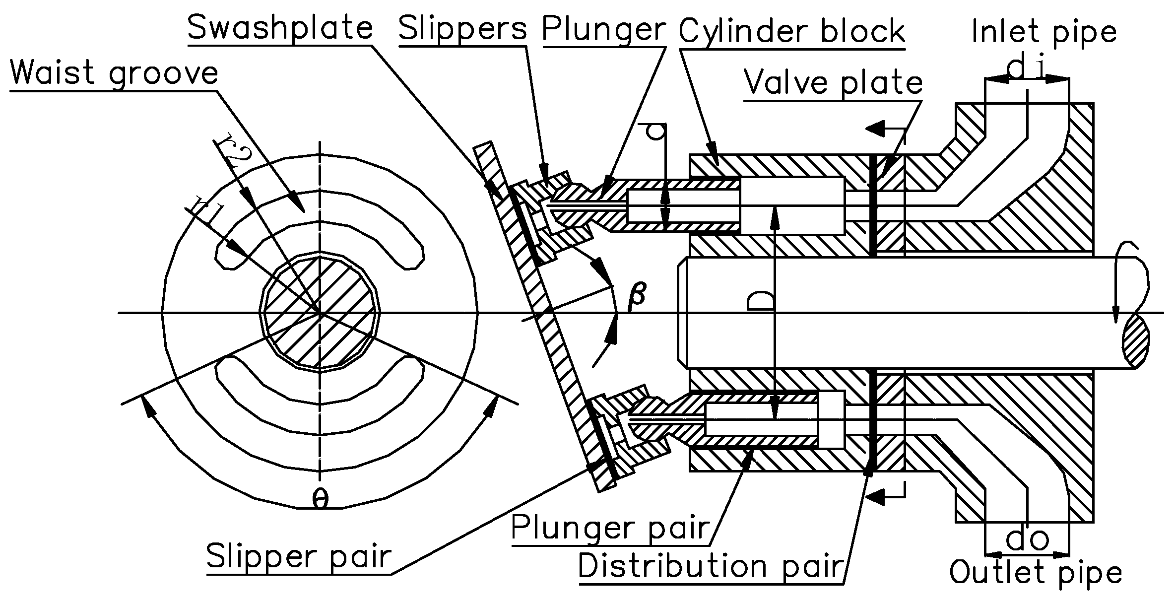
A swashplate axial piston pump is composed of a drive shaft, port plate, oil cylinder, plunger, slipper, swashplate, and other key components. The motion characteristics of the piston pump mainly depend on three precision friction pairs, namely, the cylinder/port plate (port pair), plunger cavity/plunger (plunger pair), and swashplate/slipper (slipper pair). These three friction pairs work together to realize the conversion of mechanical energy and hydraulic energy. Although the plunger and slipper are connected by a ball joint pair, the leakage loss and friction loss of the ball joint pair are relatively small compared with those of the above three friction pairs and can be ignored [
26]. In the process of pump movement, the relative motion of the friction pairs affects the performance of the piston pump. In order to optimize the friction characteristics, we must ensure the existence of a micron-thickness liquid film between the friction pairs. The existence of this liquid film can effectively reduce friction loss but forms a gap flow channel, triggering leakage volumetric loss. In addition, the compressibility of the work material affects the volumetric efficiency. The CO
2 work material is discharged under pressure in the piston pump and undergoes a phase change from a liquid to a dense phase during the working interval. An accurate characterization of its physical parameters (density, viscosity, etc.) is crucial for any numerical simulation of a piston pump’s volumetric efficiency. In order to prevent the plunger and the plunger chamber from touching the mold, there must be a bottom gap between the plunger and the plunger chamber. The CO
2 in this part of the bottom gap cannot be discharged, resulting in a loss of CO
2 compression stagnation volume.
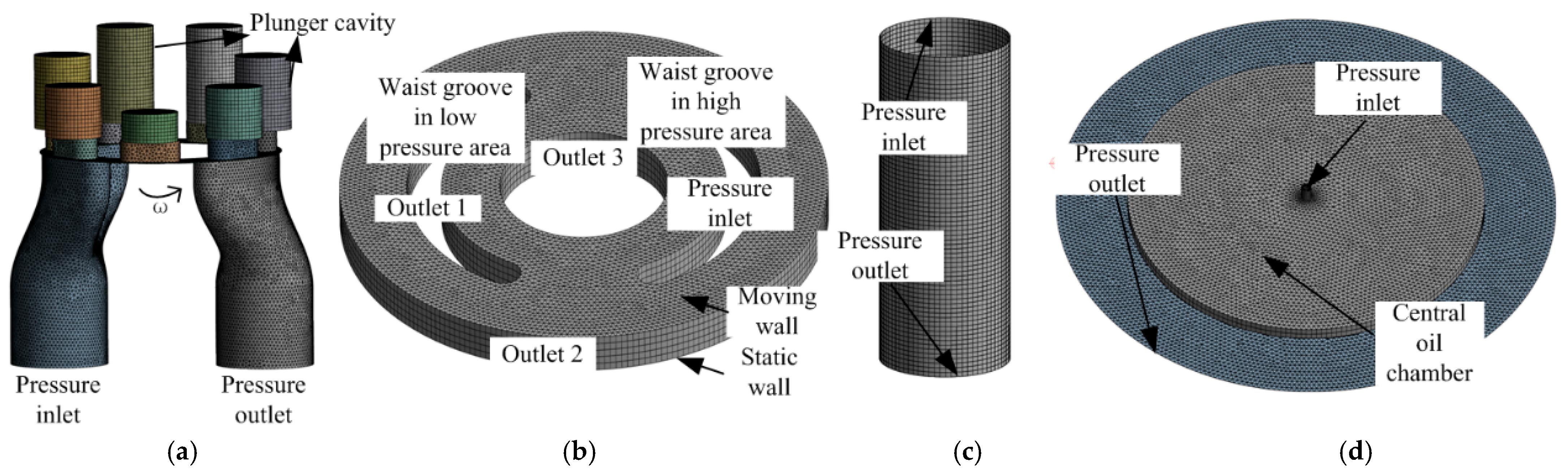
The 250CY14-1B plunger pump was selected as the research object for this study, this type of plunger pump was designed and manufactured in China and can be purchased in most manufacturers and cities at present. Three-dimensional modeling software was used to establish a geometric model of the plunger pump fluid domain and sub-film for the three friction pairs. The geometric model is shown in
Figure 1. As shown in the figure, the plunger pump fluid domain was established for the plunger cavity, a gap was reserved for plunger movement to the dead point in the plunger cavity, and the mating basin and import and export pipeline linkages were also established. A liquid film model was established for the flow distribution sub-film, plunger sub-film, and sliding shoe sub-film, and the thickness of the liquid film was taken as 10 μm [
27]. The geometrical parameters of the plunger pump fluid domain are shown in
Table 1.
4. Numerical Simulation Method and Simulation Method Validation
In a numerical simulation of the piston pump fluid domain, the flow process of fluid CO2 needs to follow the continuity equation, momentum conservation equation, and energy conservation equation in order to make the control equation closed with the introduction of a turbulence model.
where
is the fluid density; t is time;
is the velocity component in the x-direction;
is the velocity component in the y-direction; and
is the velocity component in the z-direction.
where
P is pressure;
τ is the viscous stress tensor; and
is the volumetric force acting on the fluid.
where
u is the velocity vector;
k is the heat transfer coefficient;
T is the temperature;
is the heat source term per unit volume; and
E is the total energy per unit volume of fluid, calculated as
where
e is the thermodynamic internal energy per unit mass of fluid.
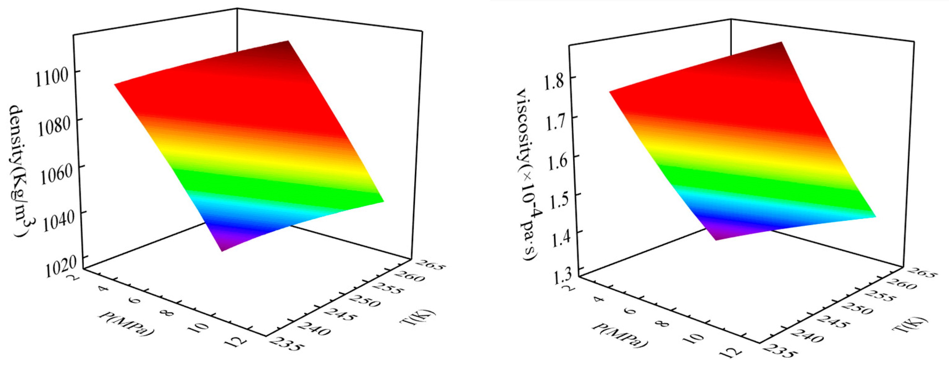
The physical properties of CO
2 are extremely complex and sensitive to changes in temperature and pressure. The phase state is variable, which causes difficulties in numerical simulations. Refprop9.1 is a software product developed by the National Institute of Standards and Technology (NIST) to reference the physical parameters of fluids. This software is widely used in scientific research, the energy and chemical industries, aerospace, and other fields, and its physical property library includes most fluids. Based on a wide range of experimental data and theoretical models, the software can accurately provide the physical properties of CO
2, including its density, viscosity, and heat conduction, which were used in this study. Due to the wide range of pressure changes during the working process of the plunger pump, in order to accurately simulate CO
2 physical properties, the real gas NIST model was selected in the numerical simulation. This model was based on the Refprop database, and the physical properties were determined according to the experimental data and the equation of state. Using this model for CO
2 ensured the accuracy of its physical properties and more accurately reflected its real flow state. By querying the Refprop software for the pressure range from 2.5 MPa to 12.5 MPa and the temperature range from 240K to 260K, physical parameters such as density, viscosity, thermal conductivity, and specific heat could be obtained. The values derived from Refprop were consistent with those from the real gas NIST model in the fluent software. Taking density and viscosity as an example, changes in the physical properties of CO
2 with temperature and pressure are shown in
Figure 5.
4.1. Numerical Simulation Method for Piston Pump Fluid Domain
A transient numerical simulation was used to open the energy equation; the inlet and outlet boundary conditions of the fluid domain of the piston pump were set as pressure boundaries of 3 MPa and 12 MPa, respectively; the operating temperature was 250K; the inlet and outlet pipelines were set as static areas; the plunger followed the rotational movement of the cylinder around the axis; the slip mesh was set to the fluid domain of the plunger cavity (mesh motion); and the operating speed was 1000rpm. Reciprocating motion was applied in the plunger cavity. For this part of the motion, a User-Defined Function (UDF) was used to impose the motion velocity. An expression of the reciprocating motion of the plunger relative to the cylinder speed is shown in Equation (5). Motion mesh technology was used to choose the layer. The actual motion conditions of the plunger pump were realized via the synergistic application of the slip mesh and UDF.
where v is the axial movement speed; ω is the angular velocity; β is the inclination angle of the swashplate; and Z is the number of plungers. The value range of n is 0, 1, 2, …, z − 1, and n = 0 describes the initial plunger.
4.2. Numerical Simulation Method for Fluid Domain of Friction Subfilm
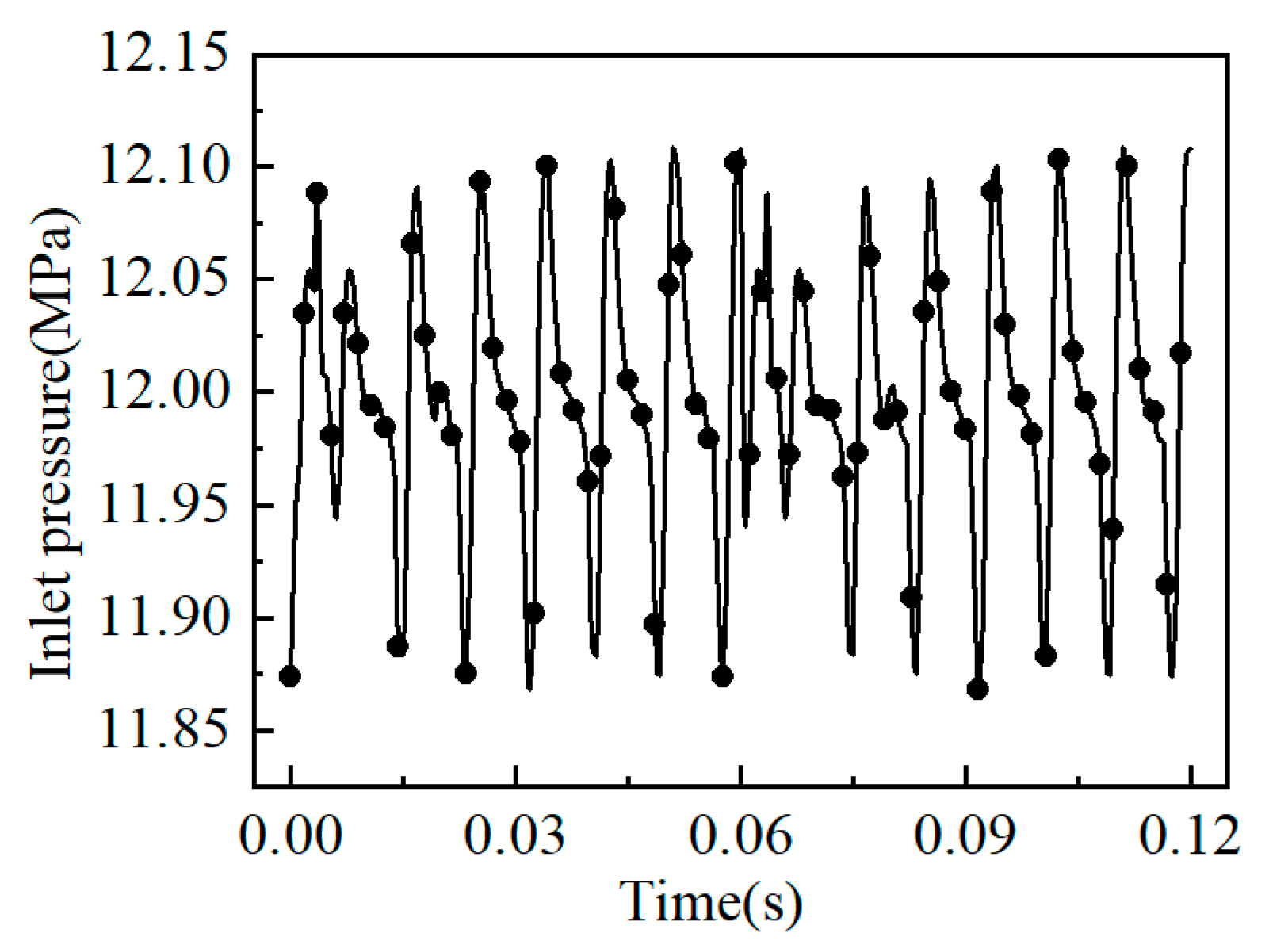
A transient numerical simulation of the mating pair, plunger pair, and sliding shoe pair was used to open the energy equation, and the outlet boundary was chosen to be a pressure outlet with a pressure of 3 MPa. The outlet pressure of the plunger pump fluctuated with the reciprocating motion of the plunger, as shown in
Figure 6. It can be seen from the figure that the waist groove of the high-pressure area of the mating pair showed the characteristic of cyclic pressure pulsation, and the pressure amplitude change corresponded to the frequency of reciprocating motion of the plunger. The curve shown in
Figure 6 was converted into a profile file as the inlet pressure value of the flow pair. Considering the shear effect generated by cylinder rotation, a moving wall was set on the contact surface between the liquid film of the flow pair and the cylinder, and the rotational speed was 1000 rpm.
The plunger sub-film at the lower dead point was the object of study. From the characteristics of plunger pump motion, it is known that the pressure in the plunger cavity is cyclic, and the phase characteristics of the transition from the low-pressure region to the high-pressure region are presented in the cycle. The pressure shown in
Figure 7 was converted into a Profile file as the inlet pressure value of the plunger sub. The plunger sub rotates around the axis under actual working conditions. A slip grid was applied to the fluid domain of the liquid membrane of the plunger sub-film with a rotational speed of 1000 rpm, and a UDF was applied against the pressure inlet surface of the liquid film to describe the axial motion. The velocity expression is shown in Equation (5).
The secondary liquid film of the slipper at the following dead point was the research object. The plunger is connected with the slipper through the ball head. The action of hydraulic pressure ensures that the slipper is close to the surface of the swashplate for rotary motion. The spherical hinge center of the slipper was projected onto the plane of the swashplate for circular motion, and sliding mesh motion was applied to the secondary liquid film of the slipper at 1000 rpm.
For the plunger pump fluid domain selection of the RNG k-ε model, the friction sub-fluid film flow pattern needs to be determined by the Reynolds number. In order to match the flow sub-fluid film as an example, the Reynolds number calculation formula was used, as shown in Equation (6) [
28].
where Re is the Reynolds number;
ω is the rotational speed;
R is the equivalent radius of the sealing end face;
h is the liquid film thickness; and
μ is the liquid carbon dioxide kinetic viscosity. After this calculation, Re = 385.46, and a laminar flow model was used.
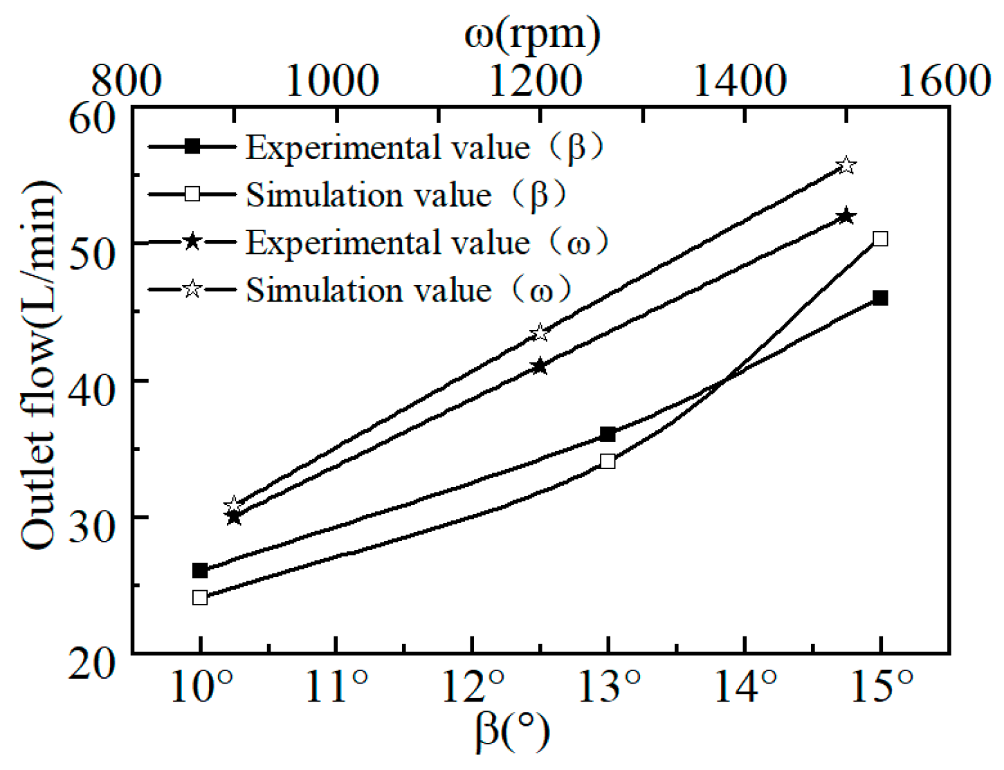
In order to verify the reliability of the numerical simulation method in the fluid domain of the piston pump in this paper, the specific working conditions of the swashplate axial piston pump in reference [
29] were selected for comparison and verification, and the numerical model consistent with the experimental conditions in the literature was established. The flow at the pump outlet with different swashplate inclination and working speed was numerically simulated and calculated; the results are shown in
Figure 8. It can be seen from the figure that the numerical simulation results of the pump outlet flow under different swashplate inclinations and working speeds were roughly the same as the experimental results in the literature. The maximum error was 7.95%, which verified the accuracy of the numerical simulation calculation model and the rationality of the boundary conditions, providing a reliable basis for the subsequent numerical simulation research.
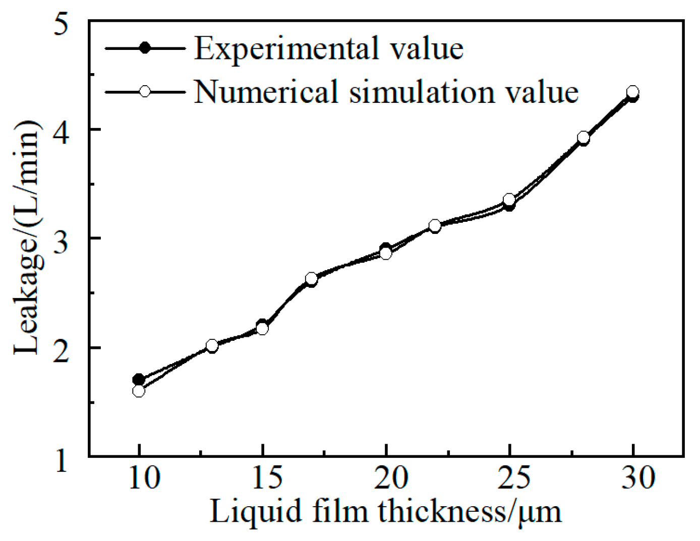
In order to verify the reliability of the numerical simulation method for the liquid film leakage volume loss, a liquid film model and the working conditions of a port pair in the literature [
30] were selected to obtain a curve of the leakage volume with the thickness of the liquid film. A comparison between the simulation results and experimental results from the literature is shown in
Figure 9. It can be seen from
Figure 9 that with an increase in liquid film thickness, the leakage amount was basically the same. The maximum error was 5.88%, indicating high accuracy and a reliable simulation method.
6. Calculations and Analyses
Before the numerical simulation, it was necessary to initialize a reasonable flow field to provide good initial conditions and to monitor the loss of pump compression retention volume and leakage of the friction pairs to judge whether the calculation results converged. Taking two rotation cycles as an example, it was found that the outlet flow of the plunger pump was stable and the flow was conserved.
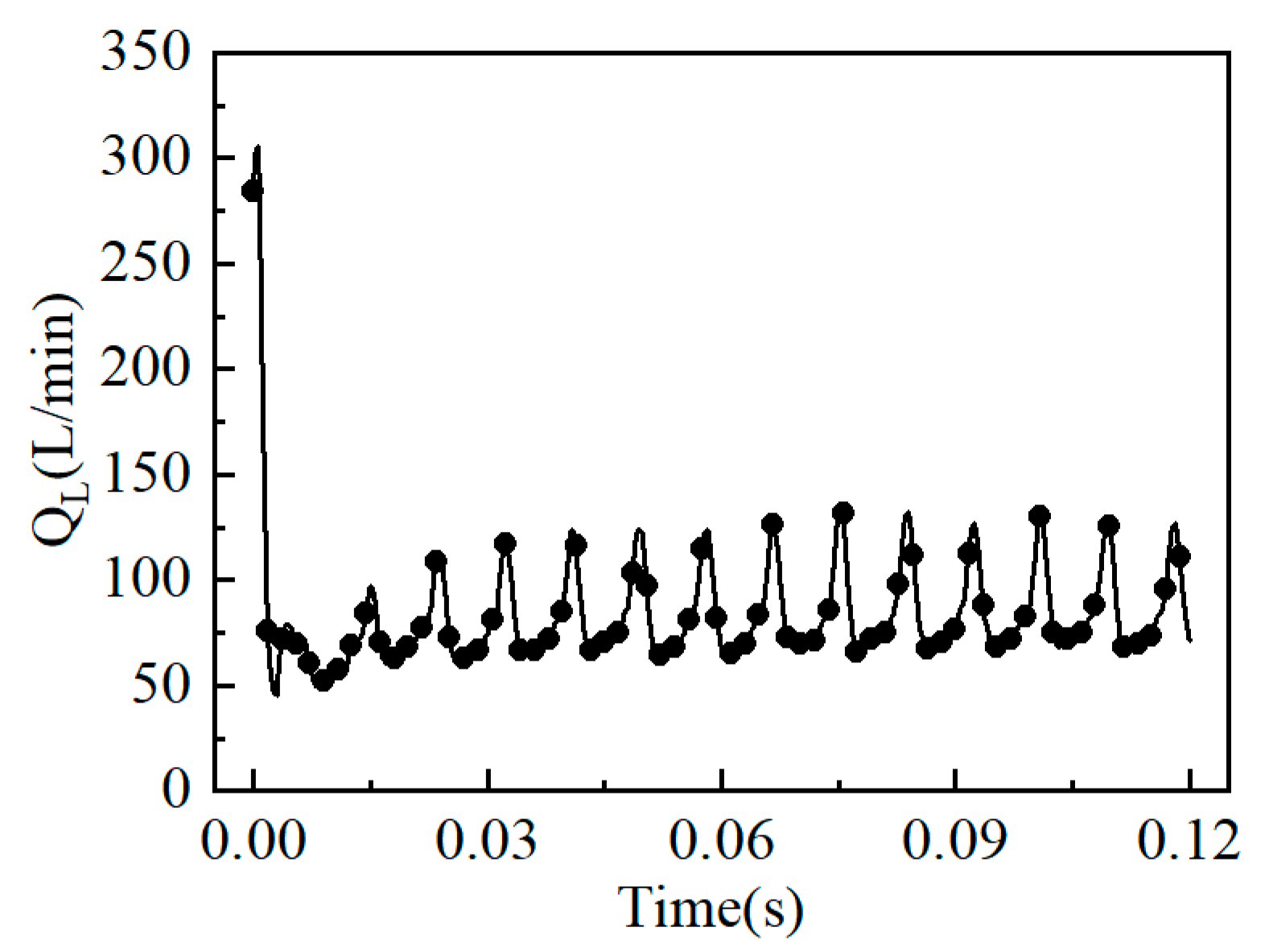
The loss of compressed retained volume was the main factor affecting the volumetric efficiency of the plunger pump.
Figure 10 shows the plunger pump’s loss of compressed retained volume. The following can be seen from the figure: (1) In the pressure range of 3–12MPa, the CO
2 medium underwent a change process from a liquid to a dense phase. The dense-phase CO
2 had the characteristics of high-density liquid and low-viscosity gas. From
Figure 5, it can be seen that the density, viscosity, and other physical parameters of the CO
2 changed with changes in the pressure and temperature, and the actual compressed volume changed nonlinearly. This deviated from the theoretical geometric displacement of the plunger pump, resulting in dynamic compression volume loss. (2) The following dead center plunger was taken as an example. In order to avoid rigid collision between the plunger and the top of the plunger cavity, it was necessary to ensure that there was a certain matching bottom gap between them. The bottom gap area formed a bottom gap volume. CO
2 has high compressibility under high pressure, and this part of CO
2 cannot be discharged in the bottom gap volume. This retention phenomenon causes a loss of displacement and causes secondary compression of the working fluid when the plunger returns, resulting in a loss of retention volume. (3) The compression retention volume loss of the plunger pump was 81.2L/min. According to Formula (7), under the fixed working conditions applied in this study, the compression retention volume loss of the CO
2 plunger pump accounted for 28.6% of the volumetric efficiency.
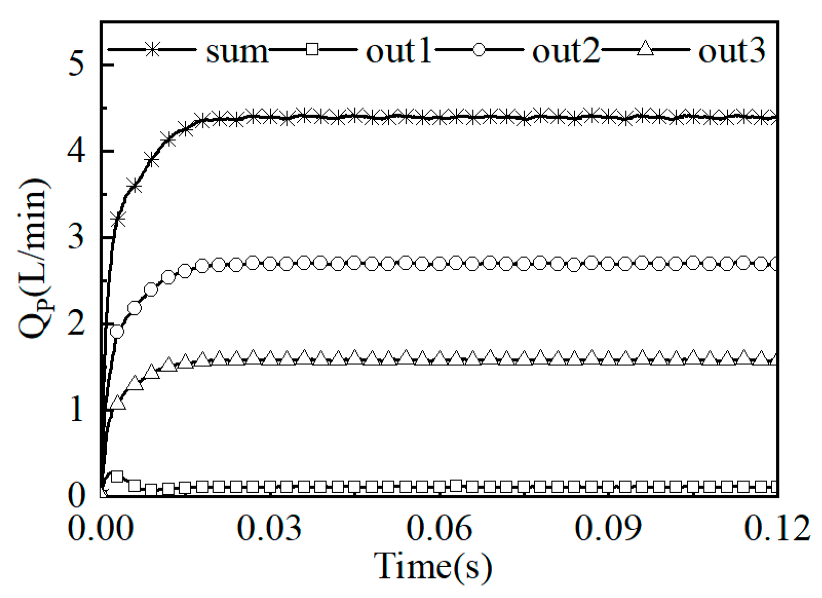
Figure 11 shows the relationship between the leakage volume loss of the flow distribution sub-film and the leakage volume loss of the three outlets. From the figure, the following can be seen: (1) After 0.02s, the leakage volume loss of the flow distribution sub-film was basically stable, and each leakage channel showed differentiation. The leakage to the side of the pump casing was the largest, accounting for 61.5% of the total leakage volume loss; the leakage to the side of the pump shaft was the second largest, accounting for 36.0% of the total leakage volume loss; and the leakage to the low-pressure area of the waist-shaped groove was the least, accounting for 3.5% of the total leakage volume loss. (2) The leakage volume loss on the piston pump flow side was 4.4L/min. According to Equation (7), the liquid film leakage volume loss on the flow side accounted for 1.5% of the volumetric efficiency.
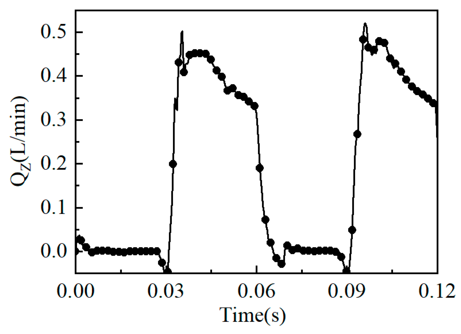
As the cylinder speed of the plunger pump was 1000 rpm, it took 0.06 s for the cylinder to complete one cycle. The plunger moved back and forth in the plunger cavity in each cycle, and the leakage volume loss of the secondary liquid film of the plunger under two motion cycles was obtained, as shown in
Figure 12. The following can be seen from the figure: (1) In the range of 0–0.03 s, the leakage volume loss of the liquid film was basically zero. Thus, at this time, the plunger moved in the low-pressure area, the inlet pressure value of the liquid film was consistent with the outlet pressure value, and no leakage occurred. In the range of 0.03–0.06 s, the inlet pressure of the liquid film of the plunger pair increased gradually. Due to the effect of the pressure difference, the leakage of the liquid film increased, and the leakage curve showed periodicity; (2) The average leakage volume loss of the liquid film of a single plunger pair was multiplied by the number of plunger pairs to obtain the leakage volume loss of the liquid film of the total plunger pairs. The total leakage volume loss of the plunger pairs was 1.5 L/min. According to Formula (7), the leakage volume loss of the plunger pairs accounted for 0.5% of the volumetric efficiency.
Figure 13 shows the leakage volume loss of the slip shoe sub-film for two motion cycles. From the figure, the following can be seen: (1) The leakage volume loss showed periodic changes with time. At 0–0.03s, the leakage volume was almost zero. At this time, the sliding shoe rotated in the low-pressure region, the import and export pressure were the same, and there was no leakage. As the inlet pressure increased, the leakage volume gradually increased and tended to stabilize; (2) The average value of the leakage volume loss of the liquid film of a single sliding shoe vice was multiplied by the number of sliding shoe vices to obtain the total leakage volume loss of the liquid film of the sliding shoe vice, which was 9.8L/min. According to Formula (7), the leakage volume loss of the sliding shoe vice accounted for 3.4% of the volumetric efficiency.


