Abstract
This study presents the experimental results of an energy harvesting system comprising a cylindrical bluff body coupled with a cantilever beam. A piezoelectric sensor was installed on the beam to generate electrical voltage during the object’s vibrations at the beam’s free end. The research aimed to evaluate the impact of the bluff body’s mass and diameter on the efficiency of the piezoelectric energy harvesting system. Vibrations of the test object were induced by airflow within a chamber of a closed-loop wind tunnel. Five different bluff body masses were analyzed for each of three cylindrical diameters across an airflow velocity range of 1 m/s to 10 m/s. These experiments allowed for the recording of a series of voltage signals over time. The signals were then subjected to Fast Fourier Transform (FFT) analysis. Subsequently, the relationship between vibration frequency and airflow velocity was examined. The peak-to-peak voltage value was also analyzed to provide an overall assessment of the energy harvesting efficiency of the system under investigation. Finally, the 0–1 test for chaos was additionally employed as a diagnostic tool to assess the complexity of system dynamics based on time series data. This test allowed for distinguishing between oscillatory behavior and cases where the system became trapped in a potential well, revealing key transitions in dynamic regimes.
1. Introduction
Vortex-induced vibration (VIV) is a dynamic phenomenon characterized by oscillatory forces generated on bluff bodies immersed in fluid flow, resulting from the periodic shedding of Kármán vortices. Along with galloping, flutter, and buffeting, VIV belongs to the family of aeroelastic vibratory phenomena, which are critically important in mechanical engineering, aerospace engineering, and wind energy. VIV primarily manifests as oscillations of the object perpendicular to the flow direction. Galloping is an instability arising from the nonlinear dependence of aerodynamic force on displacement, while flutter involves the interaction of aerodynamic forces with multiple structural vibration modes (e.g., coupled bending and torsion). The last phenomenon, buffeting, refers to random, chaotic fluctuations in aerodynamic forces induced by turbulent flow or jet interaction. Hybrid piezoelectric wind energy harvesting systems, which utilize appropriately designed bluff bodies combining circular and angular features and operating at optimal angles of attack, can significantly enhance energy harvesting efficiency across a wide range of wind speeds by synergistically leveraging VIV and galloping [1]. The exploitation of the interaction between VIV and galloping is an effective approach to improving the energy harvesting efficiency of harvesters operating at low wind speeds [2]. A mathematical model of a hybrid wind energy generator utilizing both VIV and galloping is presented in [3]. Analysis presented in [4] indicates a significant increase in research activity within the field of VIV-based energy harvesting, with a notable rise in publications in recent years. A comprehensive review of recent advancements in flow-induced vibration energy harvesting, which holds significant potential for powering microsensors and electronic devices, is presented in [5]. An extensive overview of modeling methods for flow-induced vibrations of bluff bodies, encompassing traditional (mathematical and numerical) and novel machine learning-based approaches, is provided in [6]. Reviews of previous studies on flow-induced vibrations (FIV) is presented in [7,8].
In vortex-induced vibration (VIV), the presence of bluff bodies is crucial. These are irregularly shaped objects (e.g., cylinders, prisms, plates) that cause significant flow separation. Research has been conducted on a rigid circular cylinder with two attached piezoelectric beams in a wind tunnel [9]. Experiments revealed an optimal load resistance for maximizing power in VIV and an optimal distance between cylinders in wake-induced vibrations (WIV) for maximizing output voltage and power. The implementation of a dual series system of piezoelectric VIV energy generators is an effective method for enhancing the efficiency of energy harvesting from wind flow, significantly broadening the wind speed range over which the system operates effectively [10]. Utilizing nonlinear magnetic forces is advantageous for designing efficient and broadband VIV-based piezoelectric energy generators [11]. Results from [12] indicate that buoyancy force influences the characteristics of vortices and flows around inverted D-shaped cylinders, which in turn impacts VIV. Flow separation can lead to significant oscillations transverse to the flow direction. VIV can serve as a passive energy source harvested from wind or water flow. The design and research related to a piezoelectric device for harvesting energy from vortex-induced vibrations, intended for low-speed water flow, are presented in [13]. Such a system is termed an energy harvester. This type of system converts mechanical vibrations into electrical energy using piezoelectric or electromagnetic elements. Piezoelectric materials generate voltage when mechanically deformed and, unlike electromagnetic generators, do not require magnets, coils, or other mechatronic components. Their advantage lies in their easy integration with small bluff body structures or mounting within the housing of a vibrating object. These elements are well-suited for MEMS-scale objects (Micro-Electro-Mechanical Systems), such as powering Internet of Things (IoT) sensors. Piezoelectric generators sometimes have a more complex structure. A novel generator design consisting of a composite piezoelectric transducer placed inside a cylindrical shell is presented in [14]. This transducer utilizes two pre-bent piezoelectric beams and an additional cantilevered mass. The use of a pre-bent piezoelectric vibrator subjected only to unidirectional compressive stress aims to increase transducer reliability by avoiding tensile stresses, which are more detrimental to piezoelectric materials.
The most commonly used piezoelectric material is lead zirconate titanate (PZT). Other materials include zinc oxide (ZnO), polyvinylidene fluoride (PVDF), and lead magnesium niobate-lead titanate (PMN-PT). In modern flexible wearable systems, bio-harvesting, and high-amplitude VIV harvesters, piezoelectric composites are also employed. The research presented in this paper utilized Macro Fiber Composite (MFC). This is a type of thin-film piezoactuator developed by NASA (National Aeronautics and Space Administration), where piezoelectric fibers (typically PZT) are embedded in a flexible polymer matrix and connected via interdigitated electrodes (IDT) on the surface. These electrodes are shaped as narrow, elongated strips that alternately pass one another. Such a structure provides a larger energy-receiving surface than standard electrodes, thereby increasing system efficiency. The authors of [15] investigated a device combining two electromechanical transduction mechanisms. Piezoelectric ceramic sheets (PZT) directly convert beam vibrations into electricity. A vibro-impact dielectric elastomer generator converts the energy of impacts from an internal ball striking elastomer membranes into electrical energy. These impacts are induced by the oscillations of the bluff body. A novel, fully polymer-based piezo-ion-electronic device utilizing a sandwich-structured PVDF/Nafion/PVDF (PNP) configuration was investigated by Xu et al. [16]. Owing to the mutual coupling of piezoelectric and piezoionic effects at well-defined ion–electron interfaces, this structure achieves a significant enhancement in force-to-electricity conversion efficiency, representing a promising step forward in the development of piezoelectric generator technologies.
An energy harvester system aims to achieve frequency synchronization (lock-in) with the frequency of aerodynamic vortices. This ensures the largest vibration amplitudes and, consequently, maximum energy recovery. The highest energy-harvesting efficiency occurs when the vortex shedding frequency fv synchronizes with the system’s natural frequency fn:
This phenomenon occurs for a reduced velocity U*:
where
U—flow velocity (m/s),
fn—natural frequency of the system vibrations (Hz),
d—characteristic dimension of the bluff body, usually the diameter (m).
VIV reaches maximum oscillation amplitudes when the vortex shedding frequency (Strouhal frequency) synchronizes with the natural frequency of the system within a specific range of U* (typically 4–8 for a cylinder). The key parameter for determining the amplitude and efficiency of the harvester is the mass-damping parameter ζ:
where
ζ—damping ratio (e.g., 0.01),
c—damping coefficient (related to the interaction of the object with the fluid),
k—stiffness of the system (usually related to material properties),
m—mass of the vibrating system (kg).
For a bluff body with a circular cross-section, the formula takes the following form:
where
ρ—density of the body (kg/m3),
d—diameter of the body (m),
L—length of the body (m).
A low ζ indicates larger amplitudes but also a higher risk of structural overloads. Conversely, larger ζ values suggest dampened vibrations and suppression of energy flow from the vortices to the structure. The concept of self-tuning the natural frequency of the system by employing a freely sliding bluff body on a flexible cantilever beam with an attached piezoelectric layer was presented in [17]. Original methods for investigating vortex-induced vibrations (VIV) in the form of a Virtual Physical System (VPS) and a Virtual Physical Framework (VPF) were introduced by Ren et al. [18,19]. These approaches are based on the integration of numerical simulations with real physical systems and involve the digitalization of the system’s physical parameters, such as mass, damping, and stiffness.
Other parameters for assessing vortex structure formation around a bluff body include the Strouhal number (St), which considers vortex shedding frequencies, object dimension, and flow velocity, and the Reynolds number (Re), which defines the flow characteristics (laminar or turbulent). The Reynolds number significantly impacts the efficiency of piezoelectric energy harvesting from circular cylinder VIV, affecting the generated power level, the flow velocity range where lock-in occurs, and the system’s global response characteristics [20].
The bluff body in VIV can take various shapes. The most common form is the circular cylinder, which provides stable vortex shedding. Other shapes include elongated bodies with square or prismatic cross-sections. Further variations include elastic bluff bodies in the form of plates or membranes, which can lead to flutter. The lateral surface of the body may be perforated to alter the conditions of boundary layer formation. The ability to harvest energy from vortex-induced vibrations using bluff bodies etched with different metasurface patterns was investigated in [21]. A concave hourglass amplified the VIV effect, while a concave circle, prism, and waterdrop suppressed it. Tandem configurations were also considered. The horizontal and vertical spacing between bluff bodies in such arrangements had a critical impact on the efficiency of energy harvesting from vortex-induced vibrations [22]. The use of dual fractal blunt bodies placed upstream of the main harvester significantly enhanced wind energy harvesting performance [23].
The length of the cylinder influences the stability of vortex structures along the flow axis. The ends of the object can generate additional turbulent structures, known as “end plate” effects. The advantages of these types of objects include their ability to operate at low flow velocities, with no need for external power, as well as modularity and simple construction. However, such systems also have several limitations, including a strong dependence on flow frequency, low efficiency outside the lock-in range, and limited durability under variable dynamic loads. Unusual bluff body shapes are also encountered. Research has explored energy harvesting from vortex-induced vibrations using a bluff body in the form of a cylinder inspired by the Amaryllis flower shape [24]. This study demonstrated a proportional relationship between the amplification of fluid dynamic forces and the shortening of vortex formation length. Other research has tested energy harvesting from vortex-induced vibrations using flexible piezoelectric flags [25]. Introducing a nonlinear L-shaped beam into the design of a flow-induced vibration energy harvester can lead to the utilization of higher vibrational harmonics and a significant increase in power density compared to traditional solutions [26]. A numerical study of VIV response for bluff bodies with different trailing edges revealed significant differences in amplitudes, frequencies, and vortex patterns depending on the geometry of the body’s rear section [27]. Additionally, the use of four types of metasurface patterns (convex hemisphere, convex triangular prism, convex cylinder, and convex prism) to modify a standard cylindrical bluff body was investigated [28]. The shape alteration aimed to influence aerodynamic characteristics for the purpose of suppressing vortex-induced vibrations. Depending on the applied metasurface pattern, the system’s vortex-induced vibrations could either be enhanced or suppressed compared to a smooth cylinder.
Research in [29] demonstrated that for effective VIV energy harvesting, the orientation of the bluff body should align with the beam at low wind speeds (below 2 m/s) and be perpendicular to it at high speeds (above 2 m/s). A piezoelectric energy harvesting system utilizing vortex-induced vibrations can take the form of a wind turbine, a blower that increases airflow in a tunnel, a vortex-inducing obstacle, and a circular piezoelectric converter [30]. At low wind speeds, it is possible to use an auxetic nonlinear system for harvesting energy from vortex-induced vibrations [31]. The authors of [32] propose using magnets in conjunction with piezoelectric materials that generate current under vibration. The addition of magnets introduces nonlinearity, enabling the device to operate more effectively across a broader range of vibration frequencies. A specialized element called a coupler is placed inside the pipe, while piezoelectric energy harvesting elements are positioned outside the pipe. When designing a VIV-enhanced energy harvesting device for pipeline flow, it is crucial to consider the appropriate bluff body cross-sectional shape and the natural frequency range [33]. The impact of using hybrid bluff bodies with variable cross-sections on the efficiency of energy harvesting from vortex-induced vibrations was investigated in [34]. Adding a specific type of “nonlinear stiffness” to VIV-based wind energy harvesters can significantly improve their performance and make them more effective across a wider range of wind conditions [35]. Placing a fixed square plate behind a cylinder has a significant impact on its vortex-induced vibrations. Numerical studies have shown that by varying the plate’s height and the distance between the plate and the cylinder, the intensity of the cylinder’s vibrations can either be increased or decreased [36].
A mathematical model of a piezoelectric cantilever beam with a tip mass subjected to vortex-induced vibrations was presented in [37]. The harvested energy under deterministic harmonic excitation was estimated as a function of a dimensionless velocity parameter. The analysis showed that lower damping leads to greater harvested energy, with peak power occurring near a dimensionless frequency of 1. A tri-stable vibro-impact wind energy harvester utilizing vortex-induced vibrations exhibits unique dynamic properties and potentially superior energy harvesting performance compared to traditional mono- and bistable harvesters [38]. Recent studies by Zeng [39] investigated the flow around cylindrical bluff bodies using trailing-edge splitter plates, attached fins, biomimetic surfaces, and oscillatory morphing surfaces.
The research gap addressed in this work concerns the influence of mass and velocity on the voltage generation capability of a harvester with a cylindrical bluff body mounted transversely to the axis of a cantilever beam with a piezoelectric element. While other authors have analyzed various bluff body geometries, the influence of geometric and mass parameters has not been examined in the manner presented in this study. This paper continues the authors’ previous research on energy harvesting but specifically focuses on how the aforementioned parameters affect system performance. Additionally, the 0–1 test was applied as a complementary method for analyzing the system’s dynamics, particularly to distinguish between oscillatory behavior and cases where the system becomes trapped in a potential well. The analysis above indicates the high potential of oscillating bluff bodies cooperating with piezoelectric elements for harvesting energy from airflow. Earlier studies focused on a hybrid-geometry bluff body in the form of a cylinder with a varying cross-section [40]. Subsequent research analyzed the harvester’s efficiency when coupled with springs to limit the movement of the test object [41,42]. This structure was also subjected to a combination of vibrational excitation from a shaker and airflow [43]. In this study, research and analysis of VIV generated by cylindrical bluff bodies of differing mass and diameter were undertaken. The electrical voltage induced by a piezoelectric element placed on a flexible beam due to airflow was evaluated. To investigate the nature of the system dynamics, the 0–1 test for chaos was employed as a supplementary analytical method [44,45,46]. The test enabled clear identification of chaotic and regular motion regimes depending on flow velocity and bluff body configuration. The object of study was tested in a wind tunnel. The following section of the paper presents the most important information about the research object and test rig. Subsequently, the obtained results are presented, and a qualitative and quantitative discussion is provided. A summary of the conducted research is included at the end of the paper.
2. Research Object and Test Rig
The experiments were conducted in a closed-loop wind tunnel with a closed test section measuring 700 mm × 700 mm × 1500 mm. The air speed range at the inlet to the empty test section of this tunnel extends up to 50 m/s. Flow velocity can be adjusted with an accuracy of 0.2 m/s. The turbulence intensity from the inlet to the test section, beyond the boundary layer, reaches values below 0.4% (at 50 m/s). The fan section is powered by a 30 kW three-phase AC motor. A more detailed description of the tunnel can be found in [47]. Figure 1 illustrates the experimental setup for air energy recovery systems, as prepared for the work described in this article. Figure 2 shows the research object mounted within the wind tunnel test section.
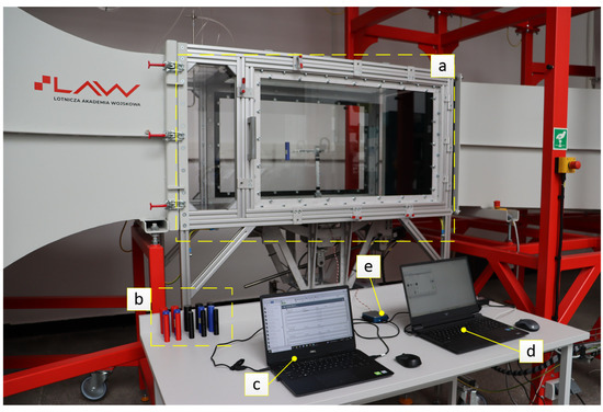
Figure 1.
Experimental setup for energy harvesting systems: a—wind tunnel test section with the mounted research object, b—set of tested bluff bodies, c—computer for recording and data acquisition from the EH system, d—computer for controlling the wind tunnel, e—data acquisition card, National Instruments USB-6002 (National Instruments, Austin, TX, USA).
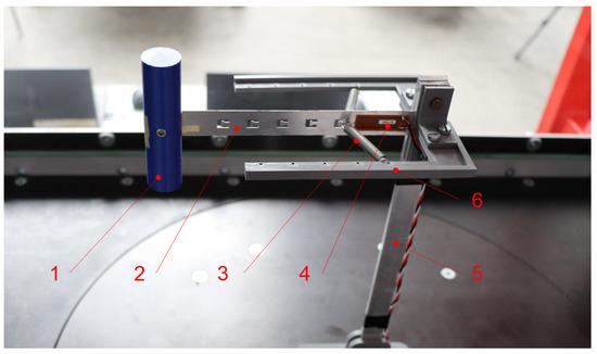
Figure 2.
View of the research object: 1—bluff body, 2—elastic beam, 3—spring arm, 4—piezoelement, 5—mast, 6—arms.
Data acquisition was performed using a National Instruments USB-6002 data acquisition card. The device features 16-bit resolution and supports up to 8 analog (differential) inputs and 13 digital I/O lines. Its maximum sampling rate is 50 kS/s. The voltage signal generated by the piezoelectric element was fed into an analog input channel with a ±10 V range. Data were recorded at a frequency of 800 Hz for at least 30 s. For the selected range, the resulting measurement resolution was ±0.3 mV, and the absolute accuracy was 6 mV (typical at full scale). Air velocity in the wind tunnel was measured using a one-piece Prandtl tube (Airflow TSI 06003, TSI Incorporated, Shoreview, MN, USA) connected to a pressure transducer (model APLISENS APR-2000G, APLISENS S.A., Warsaw, Poland). The device measures the difference between static and dynamic pressure at the inlet of the measurement chamber.. These values correspond to the measurement range set from —2500 to 2500 Pa, while the measurement accuracy of the device is 0.1%. Air velocity was set via the wind tunnel control software (Figure 1d). Prior to data acquisition at each measurement point, a minimum of 30 s was allowed for the airflow field inside the test chamber to stabilize. Each measurement was conducted after confirming system stability and signal consistency. Preliminary tests indicated high repeatability under fixed conditions; therefore, each operating point was measured once. System reset and flow stabilization procedures were applied to minimize experimental uncertainty.
The main dimensions of the bluff body and the elastic beam, onto which the piezoelectric element was affixed, are presented in Figure 3. The beam, measuring 200 × 20 × 0.5 mm, was cut from a 1050 aluminum alloy sheet. One end of the beam, 20 mm in length, was inserted into the bluff body, and the other end, of the same length, was secured in the mast. Therefore, the distance between the mast and the bluff body was 160 mm, as shown in Figure 3. The system was constructed with springs, which were attached at one end to the arms and at the other to the beam. The method of attachment to the beam utilized the specially cut slots visible in the drawing. These holes likely influenced the system’s stiffness, which will be subject to further analysis.
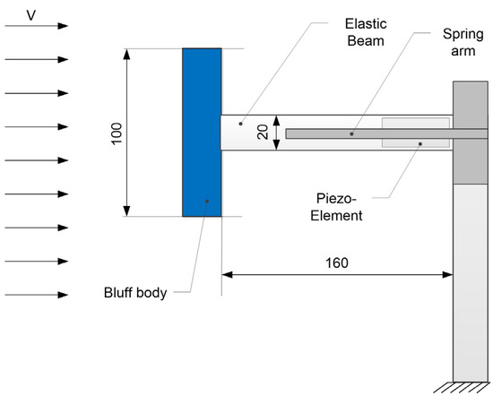
Figure 3.
Schematic view of the research object with basic geometric data.
Table 1 presents the technical parameters of the M2807-P1 piezoelectric sensor (Smart Material GmbH, Dresden, Germany) used in the energy harvesting system. This sensor features an active area of 28 × 7 mm and is capable of withstanding a maximum blocking force of 62 N, with a free strain of 1035 ppm, both with a tolerance of ±20%. It operates within a voltage range of −500 V to +1500 V and supports frequencies below 1 MHz. With a typical thickness of 300 µm and a capacitance of approximately 0.7 µF, the sensor is designed for high durability, offering a lifetime of up to 10¹¹ cycles under moderate strain conditions (<400 ppm). These characteristics make it well-suited for dynamic applications such as vibration-based energy harvesting.

Table 1.
Technical parameters of the piezoelectric sensor used in the energy harvester.
Table 2 presents the mass values of the individual bluff bodies obtained through 3D printing. In total, 15 research objects, differing in diameter and mass, were prepared for the study. Three diameters were selected: 20 mm, 25 mm, and 30 mm. Each of these diameters had five mass variants. The mass of each object was chosen based on the estimated mass provided by the G-code generation software. The actual mass values, as listed in the table, were measured using a laboratory balance.
Table 2.
Mass values of tested bluff bodies for each diameter.
3. Results and Discussion
Tests using the piezoelectric energy harvesting system were conducted to evaluate its performance under various geometric and dynamic configurations. The experiments involved three different bluff body diameters, five different bluff body masses, and a variable airflow velocity ranging from 1 to 10 m/s. This diversity of parameters enabled a comprehensive analysis of the operating conditions’ impact on the energy harvesting system’s efficiency.
During the tests, two main dynamic states were observed at different airflow velocities. At lower airflow velocities, the system typically exhibited full oscillations. In contrast, at higher velocities, the system either became trapped in a potential well, performing minimal motion, or entered a transient state—initially oscillating for a short period before the motion was gradually damped out.
To illustrate this phenomenon, two representative cases were selected, one in which the system exhibited full oscillations (Figure 4) and another in which transient states were observed (Figure 5). Additionally, to highlight the distinct dynamic behavior of the system under the same geometry, the peak-to-peak values were calculated by identifying individual maxima and minima over time series of equal length. In the case of the oscillatory response, 140 peaks were identified, whereas, for the transient response, the number of such observations was approximately four times higher. Moreover, in the oscillatory solution, the calculated peak-to-peak values consistently ranged between 10 and 11 V throughout the entire time series. In contrast, under transient conditions, these values fluctuated between 0.2 V and 2 V. These results have a direct impact on the amount of harvested energy and emphasize the importance of selecting appropriate excitation conditions for optimal harvester performance.
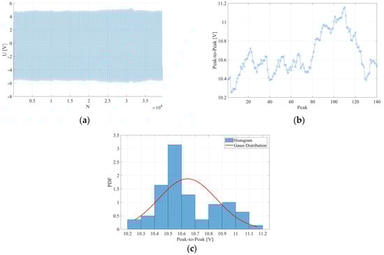
Figure 4.
Voltage signal for configuration m2, d = 25 mm, and U = 3 m/s: (a) raw voltage signal recorded from the piezoelectric element, (b) peak-to-peak voltage calculated based on local minima and maxima in the signal, (c) histogram for the mean value, μ = 10.6437 V, and the standard deviation, σ = 0.2126 V, on the normal distribution, respectively.
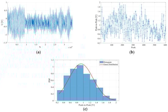
Figure 5.
Voltage signal for configuration m2, d = 25 mm, and U = 10 m/s: (a) raw voltage signal recorded from the piezoelectric element, (b) peak-to-peak voltage calculated based on local minima and maxima in the signal, (c) histogram for the mean value, μ = 0.9294 V, and the standard deviation, σ = 0.3675 V, on the normal distribution, respectively.
For the analyzed cases, the mean and standard deviation values of the peak-to-peak voltage were calculated. For the selected case representing full oscillations (Figure 4), the mean peak-to-peak voltage was 10.6437 V and the standard deviation was 0.2126 V. A total of 140 peaks were considered for this signal. In contrast, for the case representing transient states (Figure 5), the mean and standard deviation of the peak-to-peak voltage were 0.9294 V and 0.3675 V, respectively. A larger number of 600 peaks was included in the analysis due to the more irregular and less periodic nature of the signal.
The accompanying histograms further illustrate the statistical distribution of the calculated peak-to-peak values for each case. In the full oscillatory regime (Figure 4c), the histogram shows a tightly clustered distribution centered around the mean value, indicating a highly stable and periodic signal. In contrast, the transient regime (Figure 5c) exhibits a broader distribution with a higher standard deviation, reflecting increased signal variability and the absence of stable oscillatory patterns.
The next step in observing the system’s dynamics was the identification of its characteristic frequency at different airflow velocities (Figure 6). In this case, the dominant amplitude peak in the frequency spectrum was taken as the resulting frequency value. The results did not reveal a clear distinction between the oscillatory and transient responses; however, a slight decrease in frequency was observed at higher airflow velocities. The FFT (Fast Fourier Transform) results were consistent, showing a gradual shift in resonance frequency depending on the bluff body mass—specifically, the highest resonance frequency was observed for mass M = 1, while the lowest was observed for mass M = 5, for each bluff body diameter. This trend confirms the expected physical behavior of the system, where increased mass leads to lower natural frequencies due to higher inertia. It is also worth noting that the spacing between frequency peaks became narrower with increasing mass, suggesting reduced sensitivity to excitation conditions. These findings may be crucial for tuning the energy harvesting system to specific flow conditions, especially in applications where the available excitation frequency range is limited.
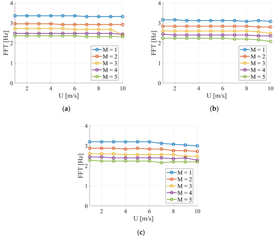
Figure 6.
Characteristic frequency (maximum) components of the voltage signal in the frequency domain for different bluff body diameters: (a) d = 20 mm, (b) d = 25 mm, (c) d = 30 mm.
The next step in the analysis, following the initial verification of the system dynamics, was to calculate the RMS (Root Mean Square) value of the voltage generated by the system under varying wind flow velocities ranging from 1 to 10 m/s, with the RMS calculated as the average value over the entire 30 s signal. In the case of the smallest diameter of 20 mm, all tested masses resulted in oscillatory behavior, and the system was the most voltage-efficient for the three smallest masses. For the two largest masses, oscillations still occurred, but with very small amplitudes, which translates into a low value of the generated voltage. This change may have been caused by the increased inertia of the larger masses, which required more force to generate the same displacements, resulting in smaller oscillation amplitudes and lower voltage generation. For the 25 mm bluff body, oscillatory response appeared at low airflow velocities from 1 m/s and generally diminished around 7–8 m/s. This configuration produced higher voltage than the 20 mm case, with peak output occurring between 4–6 m/s. For the 30 mm diameter, maximum voltage was observed at 3–4 m/s across all masses, with oscillations fading at 6 m/s. Although the system showed the least flexibility at this size, it operated in a narrow and more predictable velocity range.
Studies by Xing et al. [48,49] on an energy harvester with a square prism bluff body mounted transversely to the longitudinal axis of a cantilever beam with a piezoelectric element showed that the RMS voltage increased with increasing wind speed. In selected cases, RMS values exceeded 25 V at a wind speed of 5 m/s. Moreover, it was demonstrated that increasing the length of the protrusion on the leeward side of the bluff body generally led to higher vibration amplitudes and output power at higher wind speeds. A similar relationship between voltage and wind speed was observed for an apple-shaped bluff body mounted on a cantilever beam with a piezoelectric element [50]. As wind speed increased, the RMS voltage also increased. The maximum value approached 8 V at 5 m/s. The effect of bioinspired metasurfaces on cylindrical bluff bodies was also investigated by Yuan et al. [51]. A wavy surface proved beneficial at low wind speeds, increasing the output voltage by over 94% (0.44 V) at 0.5 m/s compared to a traditional cylindrical bluff body. A cylindrical bluff body with a modified snowflake-shaped surface, presented in [52], allowed for RMS voltage values close to 20 V at a wind speed of 2 m/s within the VIV range. A galloping triboelectric nanogenerator using a square-section bluff body mounted transversely to the axis of the beam enabled average voltage values ranging from 20 to 90 V, depending on the Reynolds number and damping ratio [53]. Hybrid bluff bodies combining square and semicircular cross-sections were studied by Huang et al. [54]. It was shown that the proposed configuration can achieve maximum RMS output voltages exceeding 30 V at a cut-in wind speed of 1.5 m/s.
The analysis of the RMS of generated voltage under varying airflow velocities revealed distinct behaviors depending on the diameter of the bluff body. For the smallest diameter of 20 mm (Figure 7a), the highest peak-to-peak voltage values (exceeding 10 V) were obtained exclusively for the smallest masses (M1 and M2), particularly at velocities ranging from 5 to 8 m/s. As mass increased (M4 and M5), there was a clear reduction in the generated voltage. This can be attributed to the increasing inertia, which dampened the beam’s vibration amplitudes. For M5, the voltage remained low (<5 V) across the entire velocity range.
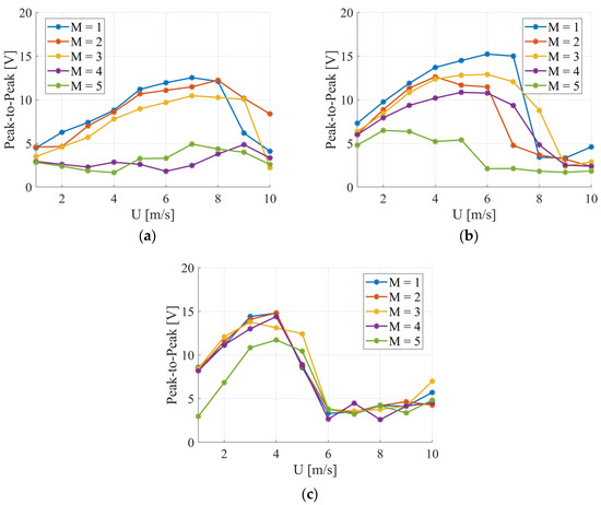
Figure 7.
Peak-to-peak voltage values calculated from the entire voltage signal for different bluff body diameters: (a) d = 20 mm, (b) d = 25 mm, (c) d = 30 mm.
In the case of the 25 mm diameter (Figure 7b), the system achieved the best overall performance. Maximum peak-to-peak voltages (exceeding 12 V) were recorded for masses M1 and M3 within the velocity range of 4–7 m/s. Mass M2 also yielded good results; however, the efficiency of voltage generation deteriorated more rapidly at higher velocities (7 and 8 m/s). Unlike the 20 mm configuration, even a larger mass (M4) produced favorable results, suggesting a beneficial matching of the system’s natural frequency with the vortex shedding frequency (lock-in). Above 7 m/s, a drop in voltage occurred, which may indicate a transition to chaotic behavior or a suppression of vibrations.
For the largest diameter of 30 mm (Figure 7c), the system’s response was more limited and predictable. Effective operation occurred exclusively within a narrow velocity range of 3–4 m/s, regardless of the mass used. The best voltages (exceeding 14 V) were achieved for masses M1 and M2. At higher velocities (from 5 to 10 m/s), the system frequently transitioned into a state of suppressed vibrations, likely due to aerodynamic damping or potential well trapping, resulting in an almost complete voltage dropout.
These results highlight the balance between voltage output, system flexibility, and stability across different geometric configurations.
Table 3 summarizes the identified flow velocity thresholds at which the system transitions from an oscillatory to a transient response for various mass–diameter configurations. The results indicate a clear dependence of the transition point on both the mass of the bluff body and its diameter.
Table 3.
Identified transition points between oscillatory and transient regimes.
For all tested masses, the lowest threshold velocities are consistently observed for the largest diameter (30 mm), suggesting that increased geometric blockage promotes an earlier onset of transient behavior. Conversely, for smaller diameters (20 mm and 25 mm), the transition occurs at higher flow velocities, and in some cases (e.g., M4 and M5 at 20 mm), no distinct transition is detected within the tested range, as indicated by the N/D (not detected) entries. This suggests that for lighter or more streamlined configurations, the system remains in an oscillatory regime over a wider range of flow velocities. These observations highlight the interplay between mass and geometric parameters in shaping the system’s dynamic response and support the hypothesis that both inertial and aerodynamic effects contribute to the onset of transient behavior.
To further investigate the dynamic response of the system, the 0–1 test for chaos was applied. This method allows for distinguishing between regular and chaotic behavior based on time series data without requiring phase space reconstruction. It is particularly useful in systems where the nature of oscillations changes with varying parameters, such as airflow velocity or structural configuration [55,56]. The test provides a quantitative measure (the K-value) indicating the presence of deterministic chaos (K ≈ 1) or regular motion (K ≈ 0). The coefficient K can be calculated using two main approaches: the mean square displacement (MSD) method and the covariance-based method. In the MSD approach, the displacement of a transformed time series is analyzed as a function of time; for chaotic systems, the MSD grows linearly, while for regular systems, it saturates at a constant level. The formula for calculating MSD is as follows [57,58]:
where
N—total number of data points in the time series,
n—time lag or displacement index, varying from 1 to a chosen maximum,
j—summation index ranging from 1 to N-n,
p(j), q(j)—transformed coordinates in the 2D phase space.
The quantity M(n) captures how far the point (p(n),q(n)) “diffuses” over time. For regular systems, M(n) remains bounded or grows slowly. For chaotic systems, M(n) grows linearly with n.
The covariance-based approach in the 0–1 test calculates the K value by analyzing the asymptotic growth rate of the variance of a transformed time series. In chaotic systems, the transformed trajectory behaves similarly to Brownian motion, resulting in a linearly increasing variance and a K value close to 1. In contrast, for regular systems, the trajectory remains bounded, leading to sublinear growth of variance and a K value close to 0. To evaluate the growth trend of the mean square displacement M(n), the Pearson correlation coefficient K(c) is computed between M(n) and the time lag n, and it is given by [59]:
where
cov—denotes covariance operator,
Mc(n)—centered mean square displacement,
n—time lag.
In the proposed approach to applying the 0–1 test, both methods were used, comparing the obtained value of the K indicator (Figure 8). The expected results are inversely proportional to those obtained for the average RMS (Figure 7). In cases of the highest voltage values, the K-value remains low, only slightly above 0 up to 0.3, indicating regular oscillations of the system with minor noise impact. This situation changes when irregular, chaotic vibrations occur; then, an increase in the K-value is expected, approaching 1, which indicates chaotic behavior. In the conducted analysis, the K-value was divided into two types: K1, calculated based on the mean square displacement (MSD) (Figure 8a,c,e), and K2, determined using the Pearson correlation coefficient (Figure 8b,d,f). This distinction allows us to capture different aspects of the system’s dynamics: K1 reflects the asymptotic growth behavior, while K2 quantifies the linear correlation structure in the transformed phase space.
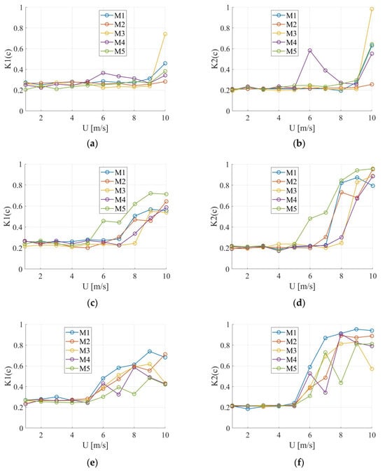
Figure 8.
Results of the 0–1 test for chaos for different bluff body diameters: (a,b) d = 20 mm, (c,d) d = 25 mm, (e,f) d = 30 mm. (a,c,e) K1—mean square displacement (MSD); (b,d,f) K2—Pearson correlation coefficient.
In the case of the MSD approach, the effectiveness of the method is less noticeable for the smallest diameter, 20 mm, due to the presence of oscillations across nearly the entire range of airflow velocities. A noticeable change in the K1 value occurs only at the highest airflow velocity, U = 10 m/s, where the indicator increases above 0.3 for almost all masses, suggesting the system transitions out of the regular motion. For the second diameter of 25 mm, when calculating K using the MSD approach, an increase in the indicator occurs at the point where the system transitions out of oscillatory behavior. This transition takes place at flow velocities between 5 and 8 m/s, inversely proportional to the average RMS results, which confirms the effectiveness of the method and its ability to capture the system’s dynamics. A similar trend is observed for the largest diameter of 30 mm, where a linear increase in the K-value begins at a flow velocity of 5 m/s. When estimating the K2 indicator, the transition from oscillatory dynamics to chaotic behavior is clearly visible. For the smallest diameter, 20 mm, a significant increase in the indicator occurs at a flow velocity of 10 m/s. For the remaining diameters, 25 mm and 30 mm, the behavior is similar to that observed for the indicator calculated using the MSD method; however, the K2 values are noticeably higher and convey the system’s dynamics more effectively. For oscillatory solutions, the K2 value fluctuates around 0.2.
The 0–1 test for chaos proved to be an effective tool for identifying transitions between regular and chaotic dynamics in the analyzed system. Among the two applied approaches, the covariance-based method (K2) provided higher sensitivity and clearer distinction of dynamic regimes compared to the MSD-based method (K1), especially for intermediate (25 mm) and large (30 mm) diameters. Overall, K2 demonstrated better capability in capturing the onset of chaos, making it the preferred method for characterizing system behavior in this context.
The observed transitions between fully oscillatory states and chaotic behavior suggest the presence of nonlinear dynamic mechanisms, which may be amplified by variations in the geometry and mass of the bluff body. Larger diameters lead to earlier flow separation, increasing the nonlinearity of the structural response. When combined with higher mass (and thus greater inertia), the system transitions more rapidly into a state of decaying vibrations, particularly in the absence of coupling with the vortex shedding frequency. The application of the 0–1 test for chaos enabled a detailed identification of transitions from regular to chaotic system behavior under varying flow conditions and geometric–mass configurations. Table 4 presents the threshold airflow velocities at which the calculated K-values exceed 0.4, indicating the onset of chaotic dynamics. Two computational approaches were used—K1, based on mean square displacement (MSD), and K2, based on Pearson correlation—allowing for a comprehensive assessment of the system’s nonlinear response.
Table 4.
Airflow velocity thresholds (U [m/s]) for the onset of chaos (K ≥ 0.4) identified using MSD-based (K1) and correlation-based (K2) 0–1 test approaches.
The results show that the correlation-based method (K2) consistently provides clearer and more sensitive detection of transitions across all tested cases, particularly for bluff bodies with intermediate (25 mm) and large (30 mm) diameters. These configurations exhibited earlier transitions into chaos, confirming the significant role of aerodynamic blockage and inertial effects. In contrast, for the smallest diameter (20 mm), chaotic behavior was observed only at the highest flow velocities, and, in several cases, no transition was detected, indicating sustained regular oscillations. These findings underline the effectiveness of the 0–1 test, especially the covariance-based variant, in detecting complex dynamic changes and reinforce the influence of both geometric and mass parameters on the stability and chaoticity of the system.
Although the presented study focused on the variability of mass and diameter, the orientation of the bluff body relative to the flow also plays a crucial role. According to the findings in [29], the optimal orientation varies with flow velocity. As the cited study showed, at low velocities (<2 m/s), the best performance was achieved when the bluff body’s axis was aligned parallel to the beam, whereas at higher velocities (>2 m/s), better results were obtained when the body was oriented perpendicularly. This indicates that the aerodynamic forces acting on the body are highly dependent on its orientation, which affects the amplitude and frequency of the beam’s vibrations and, consequently, the energy harvesting efficiency. In the investigated setup, the cylindrical bluff body was mounted transversely to the longitudinal axis of the beam. In this configuration, the aerodynamic force acts directly in the transverse direction with respect to the beam’s axis, promoting the generation of maximum bending moments and, therefore, strong deformations in the region where the piezoelectric element is located. Transverse mounting of the bluff body is effective for exciting vortex-induced vibrations (VIV), provided that frequency synchronization (lock-in) occurs between the vortex shedding and the system’s natural frequency. However, at higher flow velocities (around 10 m/s) or for heavier bluff bodies (M4 or M5), the system may experience so-called potential well trapping, which results in the suppression of vibrations. This is most likely due to increased aerodynamic forces that dampen rather than excite oscillations. The lack of asymmetry stemming from the cylindrical shape of the bluff body leads to energy harvesting via classical VIV mechanisms. This does not result in the so-called galloping effect, which typically occurs with asymmetrical cross-sections. Therefore, in the examined configuration, no synergistic VIV–galloping phenomenon was present.
In the presented experiment, the mass of the bluff body was uniformly distributed throughout its volume, which directly resulted from the use of 3D printing technology with a homogeneous material. This configuration provided good control over the total mass and its repeatability; however, it did not allow for an analysis of how the distribution of mass along the body’s axis affects the system’s dynamic behavior. The mass distribution of the bluff body can significantly influence the dominant vibration modes and their energy efficiency. Concentrating mass near the attachment point of the bluff body to the beam will affect the moment of inertia of the system with respect to the fixed point. It can be expected that this will impact the dynamic response (amplitude, frequency), the possibility of achieving resonance with the vortex shedding frequency, and the efficiency of voltage generation by the piezoelectric element. Therefore, a promising direction for further research could involve introducing controlled anisotropy in the mass distribution—for example, through the use of gradient infill structures in 3D printing or additional point loads.
In the conducted experiments, two dynamic system limitations were observed: potential well trapping and a limited effective operating range resulting from a narrow lock-in range. The first phenomenon, potential well trapping, primarily occurred with larger bluff body masses and higher flow velocities. It involved the system transitioning into a static or quasi-static state. In this state, the bluff body did not undergo full oscillations but remained near its equilibrium position, significantly reducing the beam’s vibration amplitude and the generated piezoelectric voltage. This mechanism is fundamentally caused by an increase in inertia and aerodynamic damping forces, which prevent effective vibration excitation. The second phenomenon, the narrow effective operating range, stems from the system’s strong dependence on the synchronization of the vortex shedding frequency with its natural frequency. This range varied for each bluff body mass and diameter configuration, as confirmed by observations of changes in vibration frequency and RMS voltage values as a function of flow velocity. Outside the lock-in range, the system either generated chaotic vibrations (with reduced energy harvesting efficiency) or became inactive. Both phenomena limit the long-term performance of the energy harvester, especially in environments with variable flow conditions, such as natural wind. Consequently, to ensure stable and continuous system operation, it is essential to implement adaptive mechanisms for tuning the system’s dynamic parameters, such as variable stiffness, movable mass, or modified bluff body geometry. This presents a challenge for future research in this field.
4. Conclusions
This paper presents a comprehensive experimental and numerical analysis of the influence of bluff body mass and diameter on the efficiency of a piezoelectric energy harvesting system under airflow conditions. The conducted studies allowed for a detailed evaluation of the system’s dynamics depending on its geometrical configuration and varying flow conditions. The experimental results demonstrated that the investigated system exhibited a diverse dynamic response—ranging from regular oscillatory vibrations to a state of being trapped in a potential well, where the vibration amplitude was severely limited. This effect is plausibly due to left-to-right symmetry breaking by a small deflection of the bluff body beam. It is sometimes called the stagnation effect with a smaller amplitude of vibration. The frequency lock limit is almost reached. The natural frequency in the stagnation limit is still present as the relaxation; however, the alternative scenario with the increasing shedding frequency [x] and larger response amplitude of vibration is possible. The competition of two solutions may lead to the chaotic response [35]. Effective energy harvesting was only achievable within a specific range of flow velocities, which enabled a full oscillatory response. This velocity range varied depending on the bluff body’s diameter and mass. The highest voltage values were obtained for configurations with a 25 mm diameter bluff body, suggesting an optimal compromise between mass, geometry, and the system’s resonant frequency. Conversely, the largest diameter (30 mm) provided predictable behavior but with a significantly narrower range of effective operation. Notably, an increase in bluff body mass led to a decrease in generated voltage, which was attributed to a reduction in vibration amplitude resulting from the system’s increased inertia. For the smallest masses, the most efficient conversion of mechanical to electrical energy was observed, especially for the 20 mm diameter bluff body, where full oscillations occurred almost throughout the entire range of tested flow velocities. Frequency spectrum analysis revealed the expected effect of bluff body mass on lowering the resonant frequency: as mass increased, system inertia rose, resulting in a decrease in resonant frequency and reduced generated voltage. Additionally, a decrease in the distance between peaks in the frequency spectrum indicated reduced system sensitivity to excitation conditions at larger masses.
For a bluff body diameter of 20 mm, the system operated effectively with smaller masses (M1, M2) within the velocity range of 5 to 8 m/s. Larger masses restricted the amplitude of vibrations, even though the system remained dynamically active. A diameter of 25 mm provided the best compromise between mass and VIV excitation. The system demonstrated peak efficiency (exceeding 10 V peak-to-peak voltage) even with medium masses and moderate velocities (4–7 m/s). For the largest bluff body diameter (30 mm), the system was more sensitive to changes in flow velocity and exhibited the narrowest effective operating range (3–4 m/s), despite an initially stable response.
A crucial aspect of the analysis was the implementation of the 0–1 test for chaos, which enabled the identification of transitions between regular and chaotic system behavior. Specifically, the approach based on the Pearson correlation coefficient (K2) proved more effective in distinguishing dynamic states compared to the classical mean square displacement (MSD) method. High values of the K index correlated with the occurrence of chaotic, irregular vibrations, which are not conducive to efficient energy harvesting.
The system effectively harvests energy only within specific, often narrow, wind speed ranges that induce full oscillations. Outside this range, the system may become trapped in a potential well or transition into chaotic states, significantly reducing efficiency. This strong dependence on flow conditions presents a fundamental limitation, hindering optimal performance across a broad range of wind speeds. Increasing the bluff body mass leads to reduced vibration amplitude and lower output voltage due to increased inertia. While smaller masses may enhance energy conversion, achieving optimal performance requires a balance between mass and geometry. Variations in bluff body diameter result in different voltage outputs and effective operational ranges. Larger diameters may stabilize system behavior but limit efficient operation to narrower wind speed bands. Accurately identifying chaotic transitions remains a challenge for reliable energy harvesting. Additional challenges include the long-term durability and reliability of piezoelectric materials. The use of simple cylindrical bluff body shapes restricts energy harvesting potential when compared to more complex geometries, indicating a direction for future research.
In summary, the conducted research confirms that optimizing the geometry and mass of the bluff body is crucial for the efficiency of piezoelectric energy harvesting systems based on VIV. The additional application of diagnostic tools for dynamic analysis, such as the 0–1 test for chaos, aids in the design and tuning process of harvester systems for variable airflow conditions.
Future work could involve employing more complex bluff body geometries, including hybrid or adaptive designs that allow for automatic adjustment to changing operating conditions. Another important direction for development remains the modeling of nonlinear flow-structure interactions and the assessment of the durability and reliability of piezoelectric materials subjected to long-term cyclic loads.
Author Contributions
Conceptualization, B.A. and Z.C.; methodology, B.A. and Z.C.; software, B.A. and P.K.; validation, G.L. and P.K.; formal analysis, B.A., Z.C. and P.K.; investigation, B.A. and Z.C.; resources, B.A. and Z.C.; data curation, B.A.; writing—original draft preparation, B.A., Z.C. and P.K.; writing—review and editing, B.A., Z.C. and P.K.; visualization, B.A. and Z.C.; supervision, G.L.; project administration, G.L.; funding acquisition, G.L. All authors have read and agreed to the published version of the manuscript.
Funding
The research was funded by the National Science Centre, Poland, under project SHENG-2, 2021/40/Q/ST8/00362.
Institutional Review Board Statement
Not applicable.
Informed Consent Statement
Not applicable.
Data Availability Statement
The data presented in this study are available on request from the corresponding author. The data are not publicly available due to privacy restrictions.
Acknowledgments
The research was conducted within the SHENG-2 project, grant number 2021/40/Q/ST8/00362, funded by the National Science Centre, Poland. The authors would like to express sincere gratitude to Jerzy Margielewicz and Damian Gąska from the Silesian University of Technology for their insightful discussions and inspiring influences to the research in 2024.
Conflicts of Interest
The authors declare no conflicts of interest.
References
- Wang, J.; Gu, S.; Zhang, C.; Hu, G.; Chen, G.; Yang, K.; Li, H.; Lai, Y.; Litak, G.; Yurchenko, D. Hybrid wind energy scavenging by coupling vortex-induced vibrations and galloping. Energy Convers. Manag. 2020, 213, 112835. [Google Scholar] [CrossRef]
- He, X.; Xiaokang, Y.; Senlin, J. Enhancement of wind energy harvesting by interaction between vortex-induced vibration and galloping. Appl. Phys. Lett. 2018, 112, 033901. [Google Scholar] [CrossRef]
- Yang, X.; He, X.; Li, J.; Jiang, S. Modeling and verification of piezoelectric wind energy harvesters enhanced by interaction between vortex-induced vibration and galloping. Smart Mater. Struct. 2019, 28, 115027. [Google Scholar] [CrossRef]
- Alias, F.; Rahman, M.A.A. A bibliometric analysis on energy harvesting from vortex-induced vibration. Cogent Eng. 2024, 11, 2386095. [Google Scholar] [CrossRef]
- Ma, X.; Zhou, S. A review of flow-induced vibration energy harvesters. Energy Convers. Manag. 2022, 254, 115223. [Google Scholar] [CrossRef]
- Wu, Y.; Cheng, Z.; McConkey, R.; Lien, F.S.; Yee, E. Modelling of flow-induced vibration of bluff bodies: A comprehensive survey and future prospects. Energies 2022, 15, 8719. [Google Scholar] [CrossRef]
- Francis, S.; Ashirbad, S. Modelling and harnessing energy from flow-induced vibration, particularly VIV and galloping: An explicit review. Ocean Eng. 2024, 312, 119290. [Google Scholar] [CrossRef]
- Alam, M.M. Flow-Induced Vibrations of Various Bluff Bodies: A Review of Blockage and Wall Effects. J. Fluids Struct. 2025, 136, 104328. [Google Scholar] [CrossRef]
- Zhang, M.; Wang, J. Experimental Study on Piezoelectric Energy Harvesting from Vortex-Induced Vibrations and Wake-Induced Vibrations. J. Sens. 2016, 2016, 2673292. [Google Scholar] [CrossRef]
- Zhou, S.; Wang, J. Dual serial vortex-induced energy harvesting system for enhanced energy harvesting. AIP Adv. 2018, 8, 075221. [Google Scholar] [CrossRef]
- Zhang, L.B.; Abdelkefi, A.; Dai, H.L.; Naseer, R.; Wang, L. Design and experimental analysis of broadband energy harvesting from vortex-induced vibrations. J. Sound Vib. 2017, 408, 210–219. [Google Scholar] [CrossRef]
- Barati, E.; Biabani, M.; Zarkak, M.R. Numerical investigation on vortex-induced vibration energy harvesting of a heated circular cylinder with various cross-sections. Int. Commun. Heat Mass Transf. 2022, 132, 105888. [Google Scholar] [CrossRef]
- Cao, D.; Ding, X.; Guo, X.; Yao, M. Design, simulation and experiment for a vortex-induced vibration energy harvester for low-velocity water flow. Int. J. Precis. Eng. Manuf.-Green Technol. 2021, 8, 1239–1252. [Google Scholar] [CrossRef]
- Wang, S.; Liao, W.; Zhang, Z.; Liao, Y.; Yan, M.; Kan, J. Development of a novel non-contact piezoelectric wind energy harvester excited by vortex-induced vibration. Energy Convers. Manag. 2021, 235, 113980. [Google Scholar] [CrossRef]
- Lai, Z.; Wang, S.; Zhu, L.; Zhang, G.; Wang, J.; Yang, K.; Yurchenko, D. A hybrid piezo-dielectric wind energy harvester for high-performance vortex-induced vibration energy harvesting. Mech. Syst. Signal Process. 2021, 150, 107212. [Google Scholar] [CrossRef]
- Xu, T.; Jin, L.; Ao, Y.; Zhang, J.; Sun, Y.; Wang, S.; Qu, Y.; Huang, L.; Yang, T.; Deng, W.; et al. All-polymer piezo-ionic-electric electronics. Nat. Commun. 2024, 15, 10876. [Google Scholar] [CrossRef]
- Sun, W.; Seok, J. A novel self-tuning wind energy harvester with a slidable bluff body using vortex-induced vibration. Energy Convers. Manag. 2020, 205, 112472. [Google Scholar] [CrossRef]
- Ren, H.; Fu, S.; Zhang, M.; Xu, Y.; Ren, H. Developing a virtual physical system for vortex-induced vibration studies of a bluff body. J. Ocean Eng. Sci. 2024, in press. [Google Scholar] [CrossRef]
- Ren, H.; Fu, S.; Zhang, M.; Xu, Y.; Ren, H. Virtual physical framework reveals vortex-induced vibration “Soar” and “Death” for a bluff body at high Reynolds numbers. Fundam. Res. 2024. [Google Scholar] [CrossRef]
- Zhang, M.; Zhang, C.; Abdelkefi, A.; Yu, H.; Gaidai, O.; Qin, X.; Zhu, H.; Wang, J. Piezoelectric energy harvesting from vortex-induced vibration of a circular cylinder: Effect of Reynolds number. Ocean Eng. 2021, 235, 109378. [Google Scholar] [CrossRef]
- Wang, J.; Zhang, Y.; Liu, M.; Hu, G. Etching metasurfaces on bluff bodies for vortex-induced vibration energy harvesting. Int. J. Mech. Sci. 2023, 242, 108016. [Google Scholar] [CrossRef]
- Chen, Y.; Qi, Z.; Ji, H.; Du, J.; Zhao, P.; Li, L. Vortex-induced vibration energy harvesting with tandem square bluff bodies: Spacing ratio effects. AIP Adv. 2025, 15, 015218. [Google Scholar] [CrossRef]
- Zheng, T.; Ren, H.; Zhang, Z.; Li, H.; Qin, W.; Yurchenko, D. Improving the wind energy harvesting performance with double upstream fractal bluff bodies. Renew. Energy 2025, 239, 122070. [Google Scholar] [CrossRef]
- Hosseini, S.; Afsharfard, A.; Zarkak, M.R.; Esfehani, J.A.; Kim, S.; Kim, K.C. Increasing vortex-induced vibration-based energy harvesting using a nature-inspired bluff body: An experimental study. Eur. J. Mech.-B/Fluids 2023, 97, 1–11. [Google Scholar] [CrossRef]
- Mehdipour, I.; Madaro, F.; Rizzi, F.; De Vittorio, M. Comprehensive experimental study on bluff body shapes for vortex-induced vibration piezoelectric energy harvesting mechanisms. Energy Convers. Manag. X 2022, 13, 100174. [Google Scholar] [CrossRef]
- Seyed-Aghazadeh, B.; Samandari, H.; Dulac, S. Flow-induced vibration of inherently nonlinear structures with applications in energy harvesting. Phys. Fluids 2020, 32, 071701. [Google Scholar] [CrossRef]
- Wang, W.; Song, B.; Mao, Z.; Tian, W.; Zhang, T.; Han, P. Numerical investigation on vortex-induced vibration of bluff bodies with different rear edges. Ocean Eng. 2020, 197, 106871. [Google Scholar] [CrossRef]
- Wang, J.; Sun, S.; Tang, L.; Hu, G.; Liang, J. On the use of metasurface for Vortex-Induced vibration suppression or energy harvesting. Energy Convers. Manag. 2021, 235, 113991. [Google Scholar] [CrossRef]
- Dai, H.L.; Abdelkefi, A.; Yang, Y.; Wang, L. Orientation of bluff body for designing efficient energy harvesters from vortex-induced vibrations. Appl. Phys. Lett. 2016, 108, 053902. [Google Scholar] [CrossRef]
- Du, X.; Zhang, M.; Chang, H.; Wang, Y.; Yu, H. Micro windmill piezoelectric energy harvester based on vortex-induced vibration in tunnel. Energy 2022, 238, 121734. [Google Scholar] [CrossRef]
- Fang, S.; Du, H.; Yan, T.; Chen, K.; Li, Z.; Ma, X.; Lai, Z.; Zhou, S. Theoretical and experimental investigation on the advantages of auxetic nonlinear vortex-induced vibration energy harvesting. Appl. Energy 2024, 356, 122395. [Google Scholar] [CrossRef]
- Hafizh, M.; Muthalif, A.G.; Renno, J.; Paurobally, M.R.; Bahadur, I.; Ouakad, H.; Ali, M.S.M. Vortex induced vibration energy harvesting using magnetically coupled broadband circular-array piezoelectric patch: Modelling, parametric study, and experiments. Energy Convers. Manag. 2023, 276, 116559. [Google Scholar] [CrossRef]
- Zheng, M.; Han, D.; Gao, S.; Wang, J. Numerical investigation of bluff body for vortex induced vibration energy harvesting. Ocean Eng. 2020, 213, 107624. [Google Scholar] [CrossRef]
- Li, H.T.; Ren, H.; Shang, M.J.; Lv, Q.; Qin, W.Y. Dynamics and performance evaluation of a vortex-induced vibration energy harvester with hybrid bluff body. Smart Mater. Struct. 2023, 32, 045016. [Google Scholar] [CrossRef]
- Li, Z.; Zhang, H.; Litak, G.; Zhou, S. Periodic solutions and frequency lock-in of vortex-induced vibration energy harvesters with nonlinear stiffness. J. Sound Vib. 2024, 568, 117952. [Google Scholar] [CrossRef]
- Liao, W.; Huang, Z.; Sun, H.; Huang, X.; Gu, Y.; Chen, W.; Zhang, Z.; Kan, J. Numerical investigation of cylinder vortex-induced vibration with downstream plate for vibration suppression and energy harvesting. Energy 2023, 281, 128264. [Google Scholar] [CrossRef]
- Adhikari, S.; Rastogi, A.; Bhattacharya, B. Piezoelectric vortex induced vibration energy harvesting in a random flow field. Smart Mater. Struct. 2020, 29, 035034. [Google Scholar] [CrossRef]
- Ma, X.; Li, Z.; Zhang, H.; Zhou, S. Dynamic modeling and analysis of a tristable vortex-induced vibration energy harvester. Mech. Syst. Signal Process. 2023, 187, 109924. [Google Scholar] [CrossRef]
- Zeng, L. Flow Control of Bluff Body. Ph.D. Thesis, The Hong Kong Polytechnic University, Hong Kong, China, 2024. [Google Scholar]
- Ambrożkiewicz, B.; Czyż, Z.; Karpiński, P.; Stączek, P.; Litak, G.; Grabowski, Ł. Ceramic-based piezoelectric material for energy harvesting using hybrid excitation. Materials 2021, 14, 5816. [Google Scholar] [CrossRef]
- Ambrożkiewicz, B.; Czyż, Z.; Stączek, P.; Tiseira, A.; García-Tíscar, J. Performance analysis of a piezoelectric energy harvesting system. Adv. Sci. Technol. Res. J. 2022, 16, 179–185. [Google Scholar] [CrossRef]
- Ambrożkiewicz, B.; Czyż, Z.; Stączek, P.; Anczarski, J.; Jachowicz, M. Enhancing Power Generation Efficiency of Piezoelectric Energy Harvesting Systems: A Performance Analysis. In Advanced, Contemporary Control, Proceedings of the XXI Polish Control Conference, Gliwice, Poland, 26–29 June 2023; Pawelczyk, M., Bismor, D., Ogonowski, S., Kacprzyk, J., Eds.; Springer Nature: Cham, Switzerland, 2023; Volume 1, pp. 261–268. [Google Scholar] [CrossRef]
- Ambrożkiewicz, B.; Czyż, Z.; Pakrashi, V.; Anczarski, J.; Stączek, P.; Koszewnik, A.; Wendeker, M.; Litak, G. Performance assessment of a piezoelectric vibration energy harvester for hybrid excitation with varying cross sections. Sensors 2024, 24, 7629. [Google Scholar] [CrossRef] [PubMed]
- Gottwald, G.A.; Melbourne, I. On the implementation of the 0-1 test for chaos. SIAM J. Appl. Dyn. Syst. 2009, 8, 129–145. [Google Scholar] [CrossRef]
- Gottwald, G.A.; Melbourne, I. On the validity of the 0-1 test for chaos. Nonlinearity 2009, 22, 1367–1382. [Google Scholar] [CrossRef]
- Gottwald, G.A.; Melbourne, I. The 0-1 test for chaos: A review. Lect. Notes Phys. 2016, 915, 221–247. [Google Scholar] [CrossRef]
- Czyż, Z.; Karpiński, P.; Ruchała, P.; Zahorski, T. Preliminary Measurements for the Identification the Influence of the Test Object Support on the Aerodynamic Characteristics. In IEEE Metrology for Aerospace, Proceedings 2024 11th International Workshop on Metrology for AeroSpace (MetroAeroSpace), Lublin, Poland, 3–5 June 2024; IEEE: Piscataway, NJ, USA, 2024; pp. 399–404. [Google Scholar] [CrossRef]
- Xing, J.; Rezaei, M.; Dai, H.; Liao, W.H. Investigating the Coupled Effect of Different Aspect Ratios and Leeward Protrusion Lengths on Vortex-Induced Vibration (VIV)-Galloping Energy Harvesting: Modelling and Experimental Validation. J. Sound Vib. 2024, 568, 118054. [Google Scholar] [CrossRef]
- Xing, J.; Rezaei, M.; Dai, H.; Liao, W.H. Suppressing Galloping-Induced Vibrations by Integrating Bluff Body with Surface Protrusions. AIP Adv. 2024, 14, 025114. [Google Scholar] [CrossRef]
- Du, W.; Liang, L.; Zhou, Z.; Qin, W.; Huang, H.; Cao, D. Enhancing piezoelectric energy harvesting from the flow-induced vibration of an apple-shaped bluff body based on topology optimization. Energy 2024, 307, 132667. [Google Scholar] [CrossRef]
- Yuan, Y.; Wang, H.; Yang, C.; Li, B.; Zhu, W.; Gui, J. A Flow-Induced Vibration Energy Harvester Based on Bioinspired Shell Surface Bluff Body. SSRN 2025, ahead of print. [Google Scholar] [CrossRef]
- Li, H.; Zheng, T.; Ren, H.; Shen, H.; Diao, B.; Han, W.; Ma, K.; Wang, T.; Chen, L. Improving Piezoelectric Wind Energy Harvesting Performance with Snowflake-Shaped Bluff Bodies. Int. J. Mech. Sci. 2025, 294, 110244. [Google Scholar] [CrossRef]
- Ma, T.; Hu, X.; Wu, D.; Yang, S.; Wu, M.; Xie, T.; Zheng, X.; Wang, Y. The Effects of Bluff Body Vibration Mode to the Output Performance Response of the Galloping Triboelectric Nanogenerator for Wind Energy Harvesting. Sens. Actuators A Phys. 2025, 374, 116662. [Google Scholar] [CrossRef]
- Huang, H.; Zhou, Z.; Zhu, P.; Qin, W.; Du, W. Enhancing Energy Harvesting through Hybrid Bluff Body at a Predefined Angle of Attack Coupling Vortex-Induced Vibration and Galloping. Ocean Eng. 2024, 312, 119029. [Google Scholar] [CrossRef]
- Cao, J.; Syta, A.; Litak, G.; Zhou, S.; Inman, D.J.; Chen, Y. Regular and chaotic vibration in a piezoelectric energy harvester with fractional damping. Eur. Phys. J. Plus 2015, 130, 103. [Google Scholar] [CrossRef]
- Syta, A.; Bowen, C.R.; Kim, H.A.; Rysak, A.; Litak, G. Experimental analysis of the dynamical response of energy harvesting devices based on bistable laminated plates. Meccanica 2015, 50, 1961–1970. [Google Scholar] [CrossRef] [PubMed]
- Gottwald, G.A.; Melbourne, I. Testing for chaos in deterministic systems with noise. Phys. D Nonlinear Phenom. 2005, 212, 100–110. [Google Scholar] [CrossRef]
- Gottwald, G.A.; Melbourne, I. A new test for chaos in deterministic systems. Proc. R. Soc. A Math. Phys. Eng. Sci. 2004, 460, 603–611. [Google Scholar] [CrossRef]
- Gopal, R.; Venkatesan, A.; Lakshmanan, M. Applicability of 0-1 test for strange nonchaotic attractors. Chaos 2013, 23, 023123. [Google Scholar] [CrossRef]
Disclaimer/Publisher’s Note: The statements, opinions and data contained in all publications are solely those of the individual author(s) and contributor(s) and not of MDPI and/or the editor(s). MDPI and/or the editor(s) disclaim responsibility for any injury to people or property resulting from any ideas, methods, instructions or products referred to in the content. |
© 2025 by the authors. Licensee MDPI, Basel, Switzerland. This article is an open access article distributed under the terms and conditions of the Creative Commons Attribution (CC BY) license (https://creativecommons.org/licenses/by/4.0/).