Article

Study on the Ash Deposition Characteristics for Co-Combustion of Zhundong Coal with Cotton Stalk

1
Xinjiang Xinye State-Owned Property Management (Group) Co., Ltd., Urumqi 830026, China
2
State Key Laboratory of Chemistry and Utilization of Carbon-Based Energy Resource, Xinjiang University, Urumqi 830017, China
3
Xinjiang Key Laboratory of Coal Clean Conversion & Chemical Engineering, College of Chemical Engineering, Xinjiang University, Urumqi 830017, China
4
Xinjiang Xinye Science and Technology Innovation Research Institute Co., Ltd., Urumqi 830023, China
*
Authors to whom correspondence should be addressed.
Appl. Sci. 2025, 15(13), 6963; https://doi.org/10.3390/app15136963
Submission received: 4 May 2025 / Revised: 3 June 2025 / Accepted: 11 June 2025 / Published: 20 June 2025
(This article belongs to the Section Energy Science and Technology)

Abstract

:
With the rapid development of renewable energy, the co-combustion of Zhundong coal and biomass has attracted more and more attention. However, the high content of alkali metals in Zhundong coal and biomass leads to serious slagging and fouling in the co-combustion process. In this study, cotton straw was selected for co-combustion with Zhundong coal. The ash deposition model was established according to the melting ration calculated by Factsage, and the ash deposition characteristics during the co-combustion of Zhundong coal and cotton stalks in the actual boiler were explored by Fluent. The results showed that the K2O content in ash increased from 0.31% to 9.31% with the increase in the blending ratio, while the contents of other components had no significant changes. In addition, with the increase in the blending ratio, the ash deposition rate increased from 0.00327 kg/(m2·s) to 0.00581 kg/(m2·s), an increase of 77.6%. The reduction in the tangential circle diameter obviously alleviated the ash deposition on the wall. When the tangential circle diameter was reduced to 400 mm, the ash deposition rate was 0.00207 kg/(m2·s), which was 37.6% lower than the original condition.

1. Introduction

Although the proportion of coal in China’s total energy consumption has been declining in recent years, it still accounted for over 53% as of 2024. Consequently, coal will remain a pillar resource in China’s energy consumption structure for a considerable period in the future. Xinjiang is rich in coal resources, particularly in the Zhundong coalfield, with an estimated reserve of approximately 390 billion tons, which was the largest integrated coalfield in China [1,2]. According to the current coal consumption, only the Zhundong coalfield has been able to meet the coal demand of China for nearly a hundred years. Zhundong coal is characterized by high volatile matter, low ash content, and low sulfur content, making it an ideal fuel for power generation [3,4]. Therefore, the large-scale development and utilization of Zhundong coal is very significant for ensuring the energy security of China.
Unlike fossil fuels, renewable energy, as a clean, low-carbon green energy source, will become the primary direction of the global energy transition in the future [5]. Biomass was a renewable energy source and was considered to be the fourth largest energy source globally, following oil, natural gas, and coal [6]. As a major agricultural country, China possesses abundant biomass resources with vast development potential. According to statistics, the annual biomass production in China reaches 3.49 billion tons, which is equivalent to about 460 million tons of standard coal. However, only 13% of biomass resources are used effectively [7]. Under the goals of carbon peaking and carbon neutrality, it is of great significance to strengthen the utilization of biomass energy for the sustainable development of clean energy in China.
Direct combustion technology is one of the primary methods of biomass utilization, Due to its low transformation and operation costs, it has been widely used in the fields of power generation and heating [8]. However, the volumetric calorific value of biomass fuels is low, resulting in increased transport and storage costs. In addition, the capacity of the biomass boiler is small, and the combustion efficiency is low, resulting in the poor economy of power plants. Compared with biomass combustion, coal–biomass co-combustion has many advantages [9,10]. Biomass has low calorific value and high volatile content, while coal has high calorific value and low volatile content. This complementary combination lowers ignition temperatures and enhances fuel ignition. Moreover, by adjusting the ratio of coal to biomass, the effects of seasonal fluctuations in the availability of biomass feedstock can be mitigated.
As a promising clean energy method, coal–biomass direct co-combustion technology still has some problems in its application. The content of alkali metal in Zhundong coal is high, which can easily cause slagging and fouling on the heating surface during combustion [11]. Similarly, the abundance of alkali metals in biomass also exacerbates the slagging and fouling problems. This leads to reduced heat transfer efficiency, increased thermal resistance, and possibly even burst pipes [12]. Therefore, investigating the slagging and fouling characteristics during coal–biomass co-combustion is critical to controlling these issues.
The ash deposition behavior during the combustion of high-alkali metal fuels plays a critical role in boiler design and fuel selection. Many scholars have carried out a lot of research on ash deposition characteristics during the co-combustion of coal and biomass [13]. Zhou et al. [14] studied the sintering and fusion behaviors of Zhundong coal ash blended with three types of biomass ash in a tubular furnace. The results revealed that corn stalk ash and rice husk ash promoted coal ash fusion, while wood chip ash inhibited it. Wang et al. [15] investigated the ash deposition characteristics of switchgrass and hardwood in a 17.58 kW biomass combustion system and demonstrated that switchgrass exhibited significantly lower ash deposition and slagging tendencies compared with hardwood. Additionally, varying excess air ratios had negligible effects on ash deposition for both fuels. Wu et al. [16] studied ash transformation and deposition during pulverized wood combustion with and without the addition of coal fly ash. The results showed that the formation of deposits at the location with a high flue-gas temperatures was characterized by a slow and continuous growth of deposits. At the location with a low flue-gas temperature, the deposit grew slowly, and the number of deposits became almost constant after a few hours. Although the addition of fly ash increased the ash’s settling rate at the location with the higher flue-gas temperature, it also significantly improved the sediment’s ability to be removed However, most existing research is centered around small-scale bench tests and pilot-scale stand tests; limited reports exist on the slagging and fouling behaviors of coal–biomass blends in full-scale industrial boilers.
Due to the diversity of raw materials and experimental costs, an increasing number of researchers are turning to CFD (computational fluid dynamics) methods to study ash deposition in full-scale industrial boilers [17,18]. To predict slagging and fouling in such combustion processes, researchers have developed numerous ash deposition models to predict ash deposition phenomena, ranging from laboratory-scale facilities to full-scale industrial boilers [19,20,21]. Fan et al. [22] proposed a model of deposit growth under slagging conditions, which was combined with a comprehensive combustion program to predict the flow field, temperature field, and growth of the deposit. The predictions indicated that numerical models can be used for the optimized design and operation of pulverized coal furnaces. By combining a gas–solid two-phase flow model, a combustion model, and a slagging model, Fang et al. [23] conducted a numerical study on the slagging characteristics of a 300 MW W-type furnace and found that slagging was considerable on the side wall of the lower furnace. However, there are few studies on the characteristics of ash deposition during the co-combustion of coal and biomass in actual boilers.
Relevant research results show that the melting behavior of ash components and the collision of melted ash particles on the heating surface are the main factors affecting ash deposition in the actual combustion process. Additionally, the movement of ash particles is closely related to the flow characteristics of flue gas in the furnace [24,25]. The tangential circle diameter of the boiler is an important parameter of tangential combustion, which has an important effect on the steadiness of the combustion and the deviation of the flue gas’s temperature at the furnace outlet. Therefore, the problem of slagging and fouling can be alleviated by adjusting the actual tangential circle diameter.
In this work, the cotton stalks, which are abundant in the Xinjiang region, were selected and blended with Zhundong coal. The change trend of ash composition under different blending ratios was analyzed, and the melting proportions of mixed ash under different conditions were calculated by Factsage. The ash deposition model was established by the user-defined function, and the ash deposition characteristics in the furnace under different blending ratios were obtained. The influence of the tangential circle diameter on the ash deposition characteristics in the furnace was further explored. These research results can provide guidance for the practical blending of Zhundong coal and cotton stalks.

2. Structure of the Boiler and Computational Model

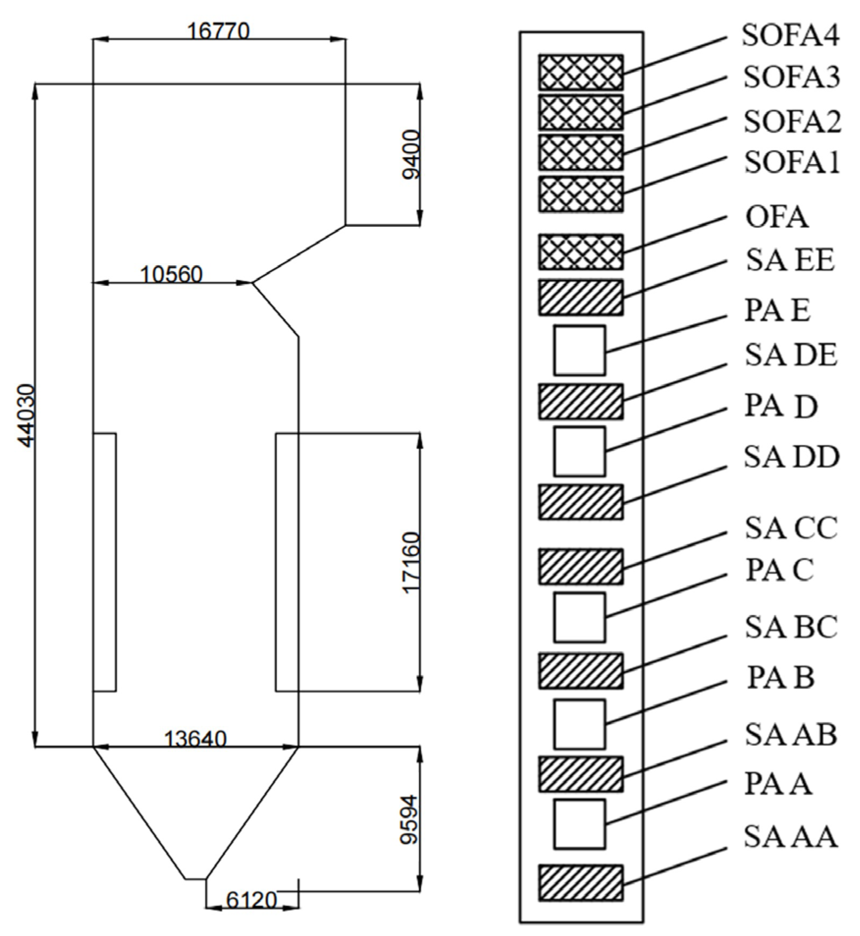
2.1. Overall Structure of the Boiler

The overall structure of the boiler and the arrangement of burner nozzles are shown in Figure 1; PA and SA represent the primary air and secondary air, respectively. The overall furnace width of the boiler was 15,390 mm, and the depth was 13,640 mm. The boiler adopted a positive-pressure, direct-blowing pulverizing system and was equipped with five medium-speed coal mills. Five burners were arranged at each corner; during normal operations, only A/B/C/D four-layer burners were put into operation. In addition, the OFA (overfire air) and SOFA (separated overfire air) were arranged at different heights of the furnace, and the furnace was divided into two relatively independent parts.

2.2. Fuel Properties and Simulation Conditions

The fuels used were Zhundong coal (ZD) and cotton stalks (CTs). The proximate analyses and ultimate analyses of the Zhundong coal and cotton stalks are shown in Table 1, and the ash compositions are shown in Table 2. It can be seen that cotton stalks exhibited an extremely high volatile content of 78.36%, while the fixed carbon content was only 27.64%. In contrast, the volatile content of Zhundong coal was 35.65%, significantly lower than that of the cotton stalks. Analyses of the ash compositions of both samples revealed that Zhundong coal ash contained relatively low levels of SiO2 (0.28%) and Al2O3 (4.58%) but a notably high Na2O content of 6.41%. In contrast, the primary component of cotton stalk ash was K2O, accounting for 51.50%, along with 9.87% Na2O. The relatively high alkali metal content (Na and K) will lead to severe slagging and fouling issues during the co-combustion of Zhundong coal and cotton stalks.
In this study, the blending ratio of cotton stalks was defined as the ratio of the heat contributed by cotton stalks to the actual heat required of the boiler. Due to the significant difference in calorific value between Zhundong coal and cotton stalks, the selected blending ratios in this study were 10%, 15%, 20%, and 25%. In our previous research, it was found that adding cotton stalks through the uppermost burner nozzle had a minimal impact on the combustion characteristics of the boiler. Therefore, this blending method was also adopted in this study. Detailed simulation parameters can be found in our previous research.

2.3. Mathematical Model

The combustion process involved multiple physical and chemical processes and their interactive coupling. In this study, all related calculations were performed using Fluent and calculated under steady state. Considering that the high-temperature flue gas inside the furnace is usually in a turbulent state, the gas-phase turbulence model in this study was solved using the standard k-ε model. In large power-station boilers, the proportion of the particle phase in the gas phase is generally less than 10%. Therefore, the discrete phase model was adopted to describe the movement of particles. The coal and biomass particles were relatively small, meeting the conditions for the assumption of uniform internal temperature, which is known as the isothermal hypothesis.
Solid fuels undergo processes such as volatile release and combustion, char combustion, and burnout inside the furnace. There may be significant differences in the relevant processes of biomass and coal combustion. In the simulation process of this paper, the release of coal volatiles adopted a two-competing-rates model, and char consumption was described by a diffusion/kinetic model. Due to the fact that the char inside biomass ignites more easily, the intrinsic model was used to depict the combustion of biomass char, which considered the non-sphericity of biomass particles [26]. Radiative heat-transfer calculations were performed using the P1 model, considering the impacts of scattering and particles, which allowed for a reduced computational load.

2.4. Ash Deposition Model Model

Generally, there are three particle adhesion theories to determine whether ash particles rebound from or adhere to surfaces: the critical viscosity model, the critical velocity model, and the molten fraction model [19,27]. Wieland et al. [20] used the critical viscosity model and the melt fraction model calculated by chemical equilibrium to conduct numerical simulations of the ash depositions from two kinds of coal and verified the results through experiments. The results demonstrated that the molten fraction model based on chemical equilibrium calculations exhibited the smallest deviation from actual observations. The proportion of molten components in ash particles was a critical parameter in determining their adhesion or rebound. Akiyama et al. [28] conducted ash deposition experiments in a pulverized coal furnace and calculated the content of molten substances in ash at different temperatures using Factsage. The comparative analysis revealed a positive correlation between the ash deposition tendency of coal samples and the proportion of molten ash fractions. Consequently, the molten fraction model was employed to evaluate the ash deposition behavior during the co-combustion of Zhundong coal and cotton stalks. The content of molten components was determined through thermodynamic calculations using the Factsage software (version 8.2), while the adhesion probability of the ash particles was calculated based on Equations (1) and (2).
Pstick = pl/(pl + ps) × 100%
ηstick = Pstick + Wstick (1 − Pstick)
Here, pl represents the liquid phase fraction in the ash particles, ps denotes the solid phase fraction in the ash particles, Pstick is the molten phase fraction of the ash particles at a specific temperature, ηstick is the adhesion probability of ash particles, and Wstick represents the molten phase fraction of the ash particles at the wall temperature.

3. Results and Discussion

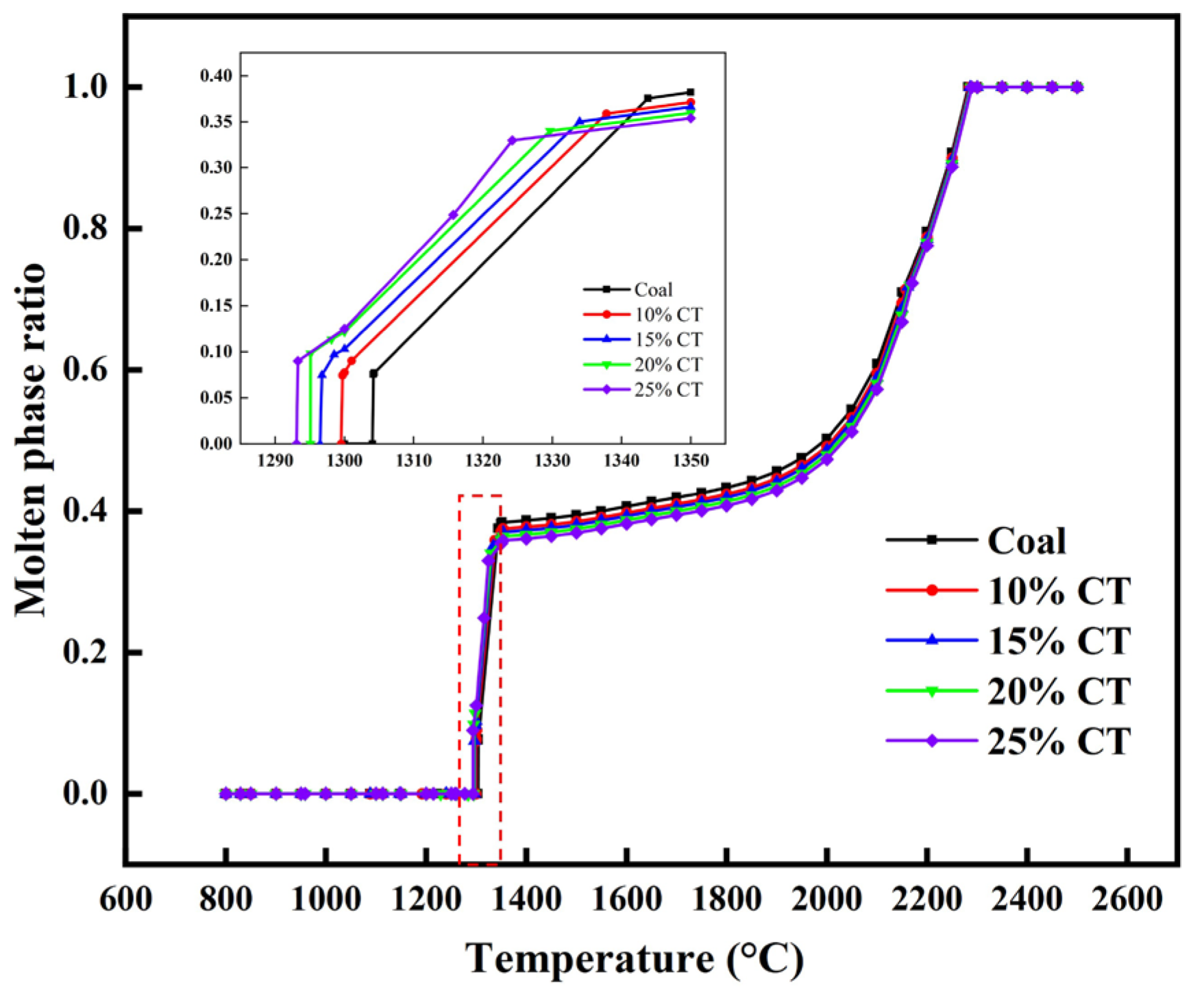
3.1. Effects of the Cotton Stalk Blending Ratio on the Ash Melting Ratio

Based on the blending ratio and calorific value of cotton stalks, the mass of cotton stalks at different blending ratios was calculated. The ash composition of the blended system under varying blending ratios was calculated, and the results are shown in Table 3. As indicated in Table 3, the K2O content in the ash significantly increased with the blending ratios of cotton stalk, rising from 0.31% to 9.31% when the blending ratio was 25%. Additionally, the content of Na2O increased from 6.41% to 7.02%. There was little difference in the contents of the other components under different blending ratios.
Based on the ash composition data in Table 3, the Factsage calculations were performed to determine the solid phase and liquid phase contents of ash under different blending ratios and temperatures. The molten fraction under corresponding conditions was further calculated, and the results were illustrated in Figure 2. It can be seen that no molten phase was formed at any blending ratio when the temperature was lower than 1573 K. In the temperature range from 1573 K–1658 K, the melting ratio increased sharply from 0 to about 0.38. Because this temperature range was quite close to the temperature range of the high-temperature zone of pulverized coal combustion, this indicated that coal ash will melt under high temperature during the combustion process. Within this temperature range, higher cotton stalk blending ratios resulted in a larger melting ratio at the same temperature. When the temperature was higher than 1658 K, the melting ratio exhibited an exponential relationship with the temperature, and the ash was fully molten at 2523 K. The melting ratio–temperature curves were segmented and fitted, and the fitting equations for each blending ratio were obtained. The R square of each fitting equation was more than 0.97, indicating that the fitting equation can well describe the trend of liquid phase proportions under different blending ratios and temperatures.

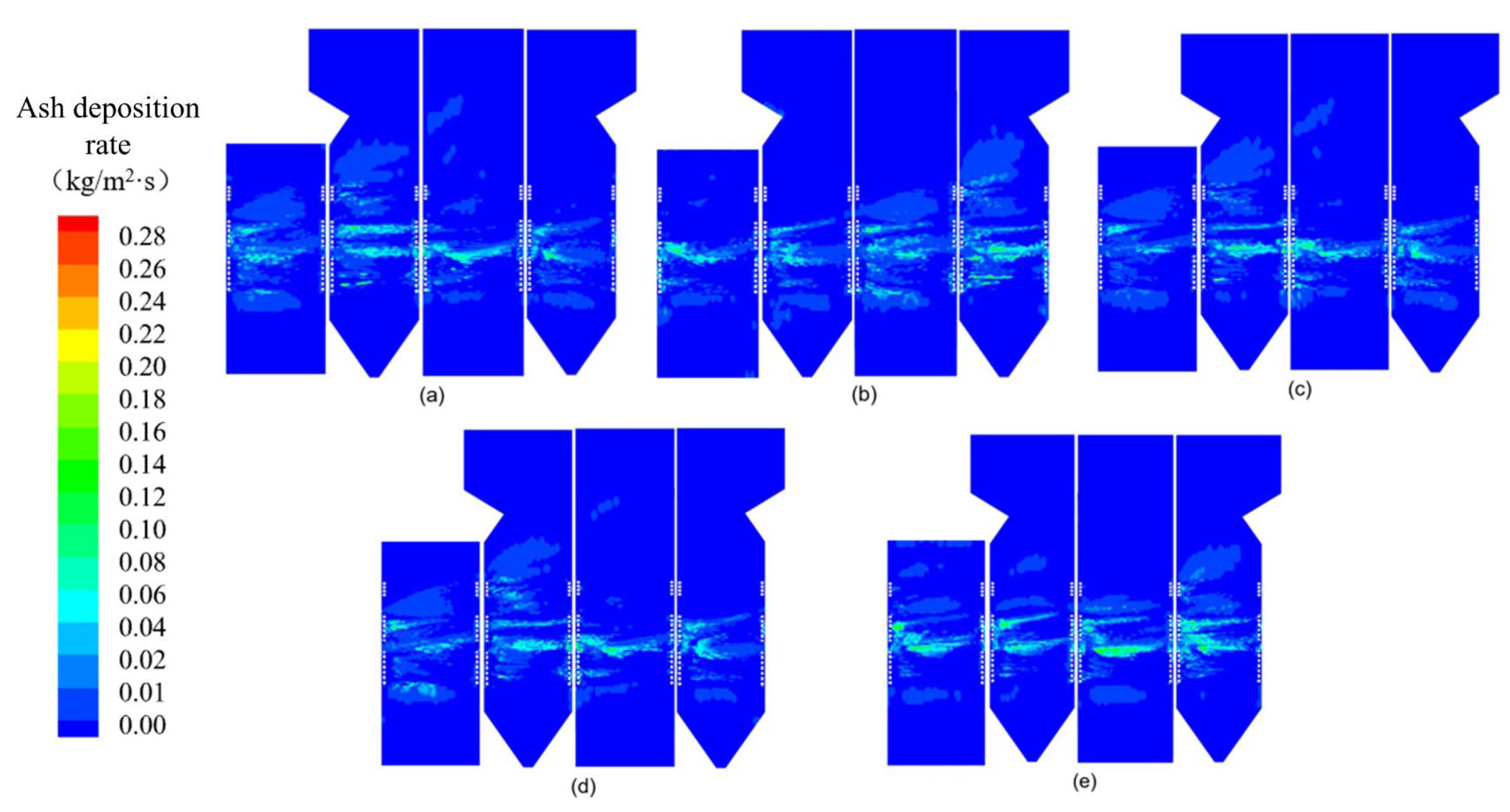
3.2. Effect of Cotton Stalk Blending Ratio on Ash Deposition Characteristics

Ash deposition distribution under different blending ratios is shown in Figure 3. It can be seen that the distribution of the ash deposition in the furnace was relatively concentrated. Among these, the most severe slagging occurred on the four walls at the height of the main combustion zone. When the blending ratio was 0, the ash deposition rate in the main combustion zone was the highest, reaching 0.22 kg/(m2·s), while the deposition rates in other areas predominantly ranged from 0.008–0.1 kg/(m2·s). The deposited ash formed band-shaped, horizontally distributed layers, and the deposition rate decreased gradually along the flue-gas flow direction. In addition, it can be seen that the distribution of the ash deposits on each wall was not uniform, which was mainly due to the uneven distribution of the flow field in the furnace.
The formation of ash deposition on the wall surfaces involved two essential processes: the melting of the ash particles under high temperatures and subsequent impingement onto heating surfaces. Therefore, the temperature and flow field distribution in the furnace were the primary factors influencing the ash deposition behavior. To further explore the reasons for the differences in the ash deposition distribution under different blending ratios, the temperature and flow field distribution in the furnace were analyzed.
By comparing the ash deposition conditions in different areas, it can be seen that the ash deposition on the lower wall was light. This is because the temperature of the bottom area of the boiler was low, and therefore the adhesion probability of the ash particles was low. As the furnace height increased, the temperature and proportion of the molten ash increased, resulting in significant ash deposition on the furnace wall. The ash deposition status on the wall surface under different blending ratios is shown in Figure 3b–e; it can be seen that with the increase in the blending ratio, the deposition rate and deposition area also increased gradually. This is mainly because at the same temperature, the ash melting ratio gradually increased with the increase in the blending ratio.
In order to reveal the cause of the uneven ash distribution, the temperature distribution at the height of the area with more serious ash deposition was further analyzed, as shown in Figure 4. The four sections are the lower, middle, and upper burner, and the middle of the SOFA. The temperature distribution of the different sections shows that the near-wall temperature exceeded 1700 K, creating favorable conditions for slagging. With the increase in the furnace height, the effect of tangential combustion decreased gradually. At furnace heights of 13.92 m, 18.92 m, and 22.16 m, the near-wall region maintained a high temperature of 1700–1850 K, corresponding to 0.37–0.40 molten ash in the mixed fuel. At the height of 27.60 m, the SOFA obviously adhered to the wall, causing a large number of molten ash particles to impact and deposit on the wall.
To further analyze the differences in ash deposition characteristics under different mixing ratios, the average ash deposition rate on the wall of the main combustion zone was calculated, and the results are shown in Figure 5. It can be seen that the average deposition rate increased gradually with the increase in the blending ratio. This may be due to the increase in alkali metal content in the ash after the addition of cotton stalks; the mass fraction of the molten phase in the ash increased, thus aggravating slagging. When the mixture ratio was 20% and 25%, the average ash deposition rate was 39.4% and 77.6%, which is higher than the deposition rate when the mixture ratio was 0%. Therefore, considering the influence of the blending ratio on the combustion status in our previous study, the optimal blending ratio of cotton stalks was determined to be 15%.

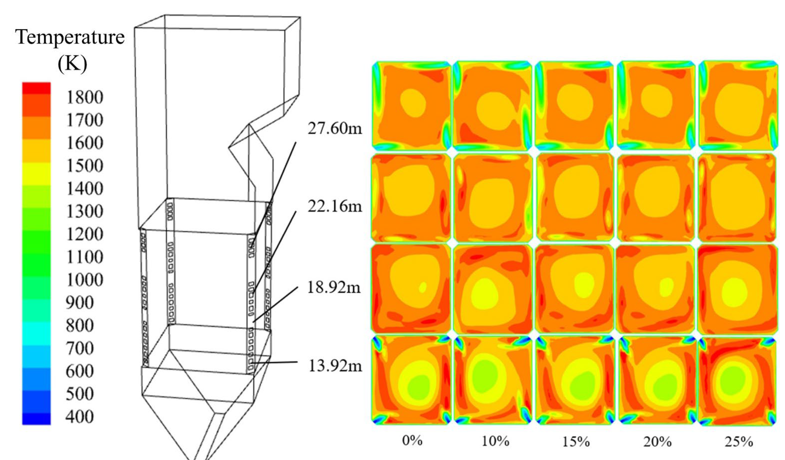
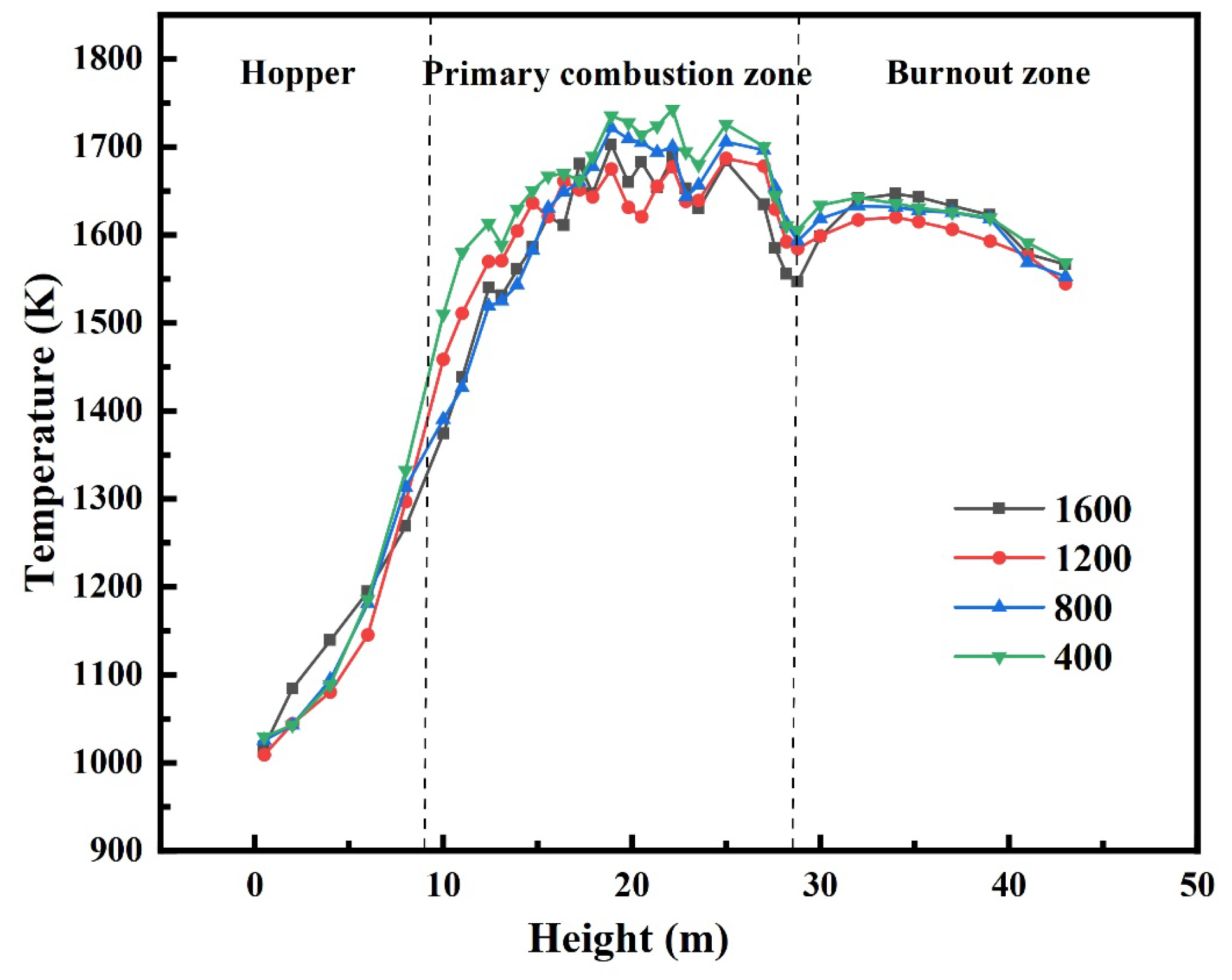
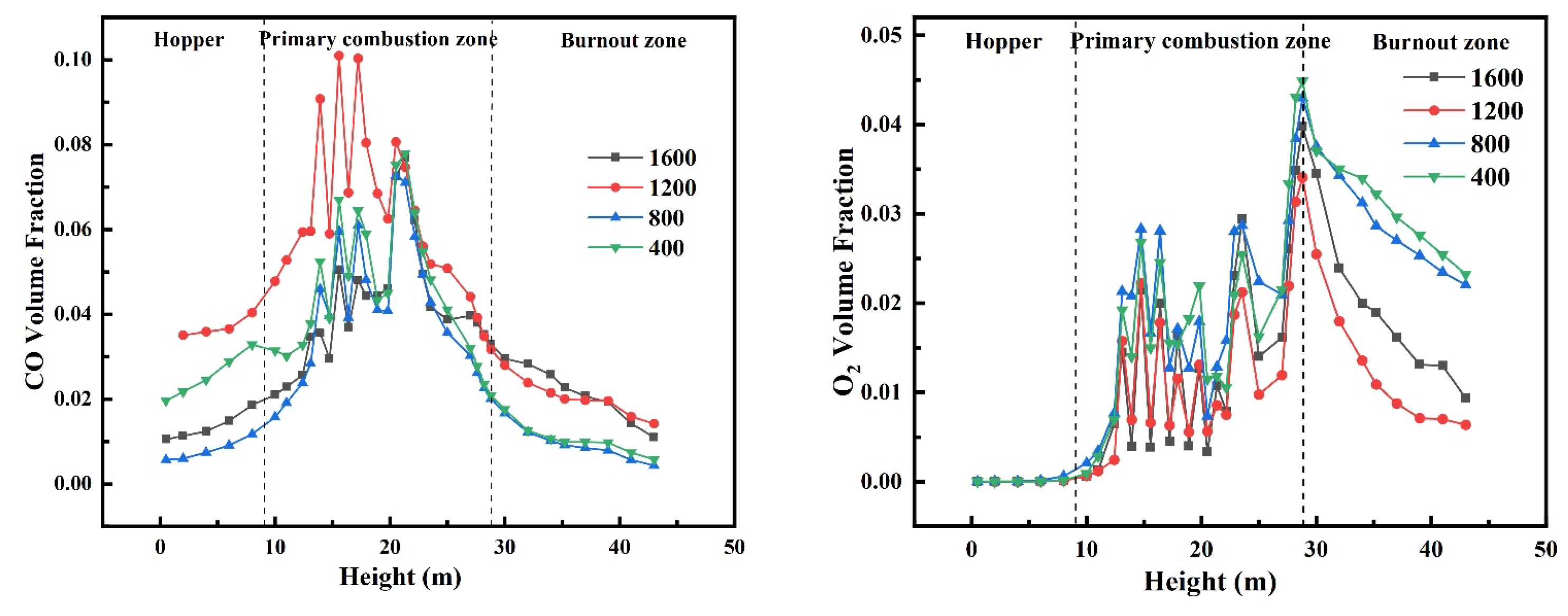
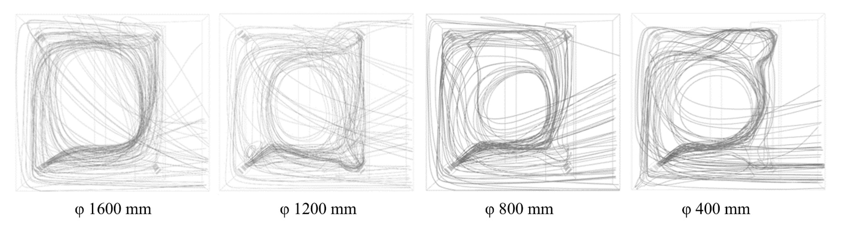
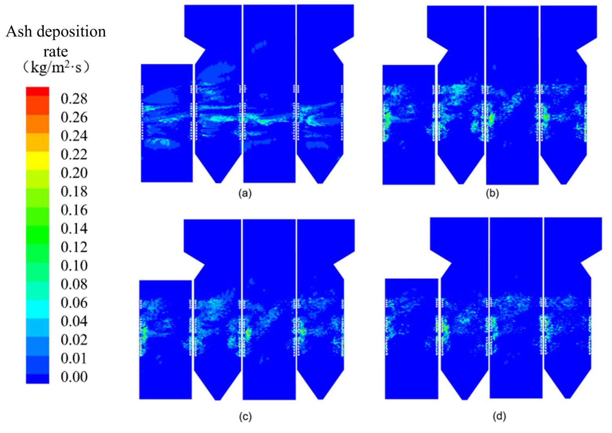
3.3. Effect of Tangential Circle Diameter on the Ash Fusion Process

As previously established, avoiding the impact of molten particles on the wall’s surface can effectively alleviate the slagging on the heating surface. Therefore, by reducing the diameter of the theoretical tangential circle diameter, more ash particles are gathered in the center of the furnace to reduce the impact of ash particles on the wall. In this study, the theoretical tangential circle diameter was reduced from 1600 to 1200, 800, and 400 mm, and the influence of the tangential circle diameter on the ash deposition characteristics was analyzed.
The temperature distribution in the furnace under different tangential circle diameters is shown in Figure 6. It can be seen that with the decrease in the theoretical tangential circle diameter, the temperature of the main combustion zone and the burnout zone increased gradually. When the theoretical tangential circle diameter was reduced to 400 mm, the maximum temperature in the main combustion zone reached above 1700 K. At the height of the furnace, about 28 m, due to the filling of the exhaust air, the fuel was completely burned to release additional heat, and the furnace temperature rose slightly. The distribution of flue gas components in the furnace under different tangential circle diameters is shown in Figure 7, and the concentration trends of CO and O2 were basically the same.
The temperature distribution at different heights of the furnace under different tangential circle diameters is shown in Figure 8. It can be seen that, with the decrease in the tangential circle diameter, the furnace section temperature increased, which was consistent with the results in Figure 7. In addition, the high-temperature area of the main combustion zone gradually migrated to the central area of the furnace, and the temperature near the wall decreased by 300–400 K accordingly.
To analyze the particle trajectories under different tangential circle diameters, the particle motion trajectory of the first layer primary air was analyzed, as illustrated in Figure 9. The results revealed significant changes in particle motion patterns as the tangential circle diameter decreased. With a larger tangential circle diameter, particles rapidly approached the wall after injection and subsequently adhered closely to the wall’s surface. This phenomenon facilitates the combustion-generated ash particles’ collision and adherence to high-temperature walls, forming deposit layers. As the tangential circle diameter decreased, the particles entering the furnace exhibited a stronger tendency toward the central region, with their trajectories deviating from the walls. Ash particles instead rotated with flue gas in the central furnace area, significantly reducing their likelihood of wall collisions and adhesion.
However, it should be noted that when the tangential circle diameter was too small, the airflow directly impinged on the central furnace region, creating a substantial angle with the actual flue-gas flow direction. This configuration induced localized recirculation phenomena in the burner zone, causing some coal ash particles to collide and adhere to walls near the burners. This mechanism may lead to severe slagging issues in the burner region.
Figure 10 illustrates the ash deposition patterns on the walls under different tangential circle diameters. As shown, the ash deposition in the main combustion zone improved with a decreasing tangential circle diameter. At a tangential circle diameter of 1600 mm, the ash deposits exhibited a band-shaped distribution, primarily concentrated on the walls surrounding the main combustion zone. When the tangential circle diameter was reduced to 1200 mm, the ash particle deposition shifted to a spot-like pattern, which was mainly localized near the burner nozzle area. With the further reduction in the tangential circle diameter, the primary deposition areas remained near the burner nozzles, but both the deposition rate and coverage range decreased significantly. This demonstrates that reducing the tangential circle diameter effectively mitigates wall slagging issues.
Figure 11 shows the average ash deposition rate on the walls of the main combustion zone under different tangential circle diameters. The average ash deposition rate on the walls gradually decreases with the reduction in the tangential circle diameter. At a tangential circle diameter of 400 mm, the ash deposition rate was 0.00207 kg/(m2·s), representing a 37.6% reduction. This further confirms that reducing the tangential circle diameter significantly alleviates ash deposition and slagging issues on the furnace’s walls. However, as the tangential circle diameter decreased, the residence time of pulverized coal within the furnace was reduced. This may lead to incomplete combustion and consequently result in a decline in boiler thermal efficiency. This trade-off highlights the need to balance ash deposition mitigation and combustion optimization when adjusting the tangential circle diameter in practical furnace operations.

4. Conclusions

In this paper, based on the ash compositions of Zhundong coal and cotton stalks at different mixing ratios, the liquid phase content at different temperatures was calculated by Factsage. An ash deposition model based on the melting ratio of coal ash was established, and the influence of cotton stalk mixing on the ash deposition characteristics of the wall of the corner tangent boiler was analyzed. On this basis, the formation process of wall ash deposition was further analyzed, and the condition of ash deposition on the heating surface was alleviated by reducing the tangential circle diameter, and the simulation calculation was carried out. The main conclusions are as follows:
(1)
With the increase in the blending ratio of cotton stalks, the content of K2O increased significantly, from 0.31% without mixing to 9.31% when the mixing ratio was 25%. While the contents of CaO, Fe2O3, and Al2O3 in the ash gradually decreased, the difference was not significant.
(2)
With the increase in the mixing ratio, the condition of wall ash deposition deteriorated gradually, and the average ash deposition rate increased significantly. The average ash deposition rate on the wall was 0.00327 kg/(m2·s) without mixing, and the average ash yield was 0.00581 kg/(m2·s) when the mixing ratio was 25%, which was 77.6% higher than that without mixing.
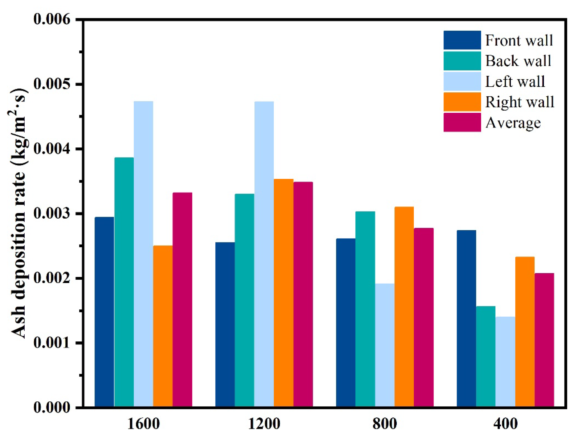
(3)
Reducing the tangential circle diameter can alleviate the ash deposition on the wall. With the decrease in the tangential circle diameter, the ash deposition changed from a zonal distribution to a point-like distribution, and the ash deposition rate and distribution area both decreased significantly. When the tangential circle diameter was reduced to 400 mm, the average ash deposition rate on the wall was reduced to 0.00207 kg/(m2·s), which was 37.6% lower than the original condition. However, the influence of reducing the circumferential diameter on the combustion efficiency of the boiler needs to be further evaluated.

Author Contributions

Conceptualization, K.L. and B.W.; methodology, B.W.; formal analysis, J.W.; investigation, F.W.; resources, B.W.; data curation, Y.Q.; writing—original draft preparation, T.L.; writing—review and editing, T.L. and N.L.; visualization, N.C.; funding acquisition, K.L. and B.W. All authors have read and agreed to the published version of the manuscript.

Funding

This research was funded by the Major Science and Technology Projects of Xinjiang Uygur Autonomous Region (2024A01005), the National Natural Science Foundation of China (NO. 22178298), the Special Project of the State Key Laboratory of Chemistry and Utilization of Carbon Based Energy Resources (Grant No. PYKT2024006), the Tianshan Innovation Team Plan of Xinjiang Uygur Autonomous Region (NO. 2023D14010).

Data Availability Statement

All data is contained within the article.

Conflicts of Interest

Authors Tianyou Li and Feng Wang were employed by the company Xinjiang Xinye State-Owned Property Management (Group) Co., Ltd. Author Ning Chen was employed by the company Xinjiang Xinye Science and Technology Innovation Research Institute Co., Ltd. The remaining authors declare that the research was conducted in the absence of any commercial or financial relationships that could be construed as a potential conflict of interest.

References

  1. Zhou, J.; Zhuang, X.; Alastuey, A.; Querol, X.; Li, J. Geochemistry and mineralogy of coal in the recently explored Zhundong large coal field in the Junggar basin, Xinjiang province, China. Int. J. Coal Geol. 2010, 82, 51–67. [Google Scholar] [CrossRef]
  2. Liu, K.; Wei, B.; Zhang, Y.; Wang, J.; Chen, L.; Wu, W.; Tan, H.; Yao, H. Fe occurrence form and slagging mechanism on water-wall during high iron Zhundong coal combustion process. Fuel 2022, 315, 123268. [Google Scholar] [CrossRef]
  3. Wang, X.; Xu, Z.; Wei, B.; Zhang, L.; Tan, H.; Yang, T.; Mikulčić, H.; Duić, N. The ash deposition mechanism in boilers burning Zhundong coal with high contents of sodium and calcium: A study from ash evaporating to condensing. Appl. Therm. Eng. 2015, 80, 150–159. [Google Scholar] [CrossRef]
  4. Wei, B.; Wu, W.; Liu, K.; Wang, J.; Chen, L.; Ma, J.; Wang, F.; Li, X.; Yang, W.; Tan, H. Investigation of slagging characteristics on middle and low temperature heat transfers by burning high sodium and iron coal. Combust. Sci. Technol. 2022, 194, 1768–1787. [Google Scholar] [CrossRef]
  5. Munawar, M.A.; Khoja, A.H.; Naqvi, S.R.; Mehran, M.T.; Hassan, M.; Liaquat, R.; Dawood, U.F. Challenges and opportunities in biomass ash management and its utilization in novel applications. Renew. Sustain. Energy Rev. 2021, 150, 111451. [Google Scholar] [CrossRef]
  6. Zhou, T.; Zhang, W.; Shen, Y.; Luo, S.; Ren, D. Progress in the change of ash melting behavior and slagging characteristics of co-gasification of biomass and coal: A review. J. Energy Inst. 2023, 111, 101414. [Google Scholar] [CrossRef]
  7. Wang, T.; Zhou, T.; Li, C.; Song, Q.; Zhang, M.; Yang, H. Development Status and Prospects of Biomass Energy in China. Energies 2024, 17, 4484. [Google Scholar] [CrossRef]
  8. Mularski, J.; Li, J. A review on biomass ignition: Fundamental characteristics, measurements, and predictions. Fuel 2023, 340, 127526. [Google Scholar] [CrossRef]
  9. Si, F.; Zhang, H.; Feng, X.; Xu, Y.; Zhang, L.; Zhao, L.; Li, L. Thermodynamics and synergistic effects on the co-combustion of coal and biomass blends. J. Therm. Anal. Calorim. 2024, 149, 7749–7761. [Google Scholar] [CrossRef]
  10. Toptas, A.; Yildirim, Y.; Duman, G.; Yanik, J. Combustion behavior of different kinds of torrefied biomass and their blends with lignite. Bioresour. Technol. 2015, 177, 328–336. [Google Scholar] [CrossRef]
  11. Liu, K.; Wei, B.; Wang, J.; Chen, L.; Kong, L.; Lu, H. Effect of atmosphere and chemical composition on ash fusion process of Zhundong high iron coal. Fuel 2025, 386, 134223. [Google Scholar] [CrossRef]
  12. Niu, Y.; Tan, H.; Hui, S. Ash-related issues during biomass combustion: Alkali-induced slagging, silicate melt-induced slagging (ash fusion), agglomeration, corrosion, ash utilization, and related countermeasures. Prog. Energy Combust. Sci. 2016, 52, 1–61. [Google Scholar] [CrossRef]
  13. Wang, Y.; Tan, H.; Wang, X.; Cao, R.; Wei, B. The condensation and thermodynamic characteristics of alkali compound vapors on wall during wheat straw combustion. Fuel 2017, 187, 33–42. [Google Scholar] [CrossRef]
  14. Zhou, H.; Ma, W. An experimental study on the effects of adding biomass ashes on ash sintering behavior of Zhundong coal. Appl. Therm. Eng. 2017, 126, 689–701. [Google Scholar] [CrossRef]
  15. Wang, Y.; Shao, Y.; Matovic, M.D.; Whalen, J.K. Exploring switchgrass and hardwood combustion on excess air and ash fouling/slagging potential: Laboratory combustion test and thermogravimetric kinetic analysis. Energy Convers. Manag. 2015, 97, 409–419. [Google Scholar] [CrossRef]
  16. Wu, H.; Bashir, M.S.; Jensen, P.A.; Sander, B.; Glarborg, P. Impact of coal fly ash addition on ash transformation and deposition in a full-scale wood suspension-firing boiler. Fuel 2013, 113, 632–643. [Google Scholar] [CrossRef]
  17. Gao, R.; Yin, S.; Song, T.; Lu, P. Numerical simulation of co-combustion of pulverized coal and biomass in TTF precalciner. Fuel 2023, 334, 126515. [Google Scholar] [CrossRef]
  18. Deng, L.; Ma, S.; Jiang, J.; Tie, Y.; Zhang, Y.; Zhu, Z.; Belošević, S.; Tomanović, I.; Che, D. Numerical Investigation on Cofiring Characteristics of Biomass Syngas and Coal in a 660-MW Tower Boiler. J. Energy Eng. 2022, 148, 04022014. [Google Scholar] [CrossRef]
  19. Cai, Y.; Tay, K.; Zheng, Z.; Yang, W.; Wang, H.; Zeng, G.; Li, Z.; Keng Boon, S.; Subbaiah, P. Modeling of ash formation and deposition processes in coal and biomass fired boilers: A comprehensive review. Appl. Energy 2018, 230, 1447–1544. [Google Scholar] [CrossRef]
  20. Wieland, C.; Kreutzkam, B.; Balan, G.; Spliethoff, H. Evaluation, comparison and validation of deposition criteria for numerical simulation of slagging. Appl. Energy 2012, 93, 184–192. [Google Scholar] [CrossRef]
  21. Yang, X.; Ingham, D.; Ma, L.; Zhou, H.; Pourkashanian, M. Understanding the ash deposition formation in Zhundong lignite combustion through dynamic CFD modelling analysis. Fuel 2017, 194, 533–543. [Google Scholar] [CrossRef]
  22. Fan, J.; Zha, X.; Sun, P.; Cen, K. Simulation of ash deposit in a pulverized coal-fired boiler. Fuel 2001, 80, 645–654. [Google Scholar] [CrossRef]
  23. Fang, Q.; Wang, H.; Wei, Y.; Lei, L.; Duan, X.; Zhou, H. Numerical simulations of the slagging characteristics in a down-fired, pulverized-coal boiler furnace. Fuel Process. Technol. 2010, 91, 88–96. [Google Scholar] [CrossRef]
  24. Zheng, Z.; Yang, W.; Yu, P.; Cai, Y.; Zhou, H.; Boon, S.K.; Subbaiah, P. Simulating growth of ash deposit in boiler heat exchanger tube based on CFD dynamic mesh technique. Fuel 2020, 259, 116083. [Google Scholar] [CrossRef]
  25. Zheng, S.; Zeng, X.; Qi, C.; Zhou, H. Modeling of ash deposition in a pulverized-coal boiler by direct simulation Monte Carlo method. Fuel 2016, 184, 604–612. [Google Scholar] [CrossRef]
  26. Yin, C.; Rosendahl, L.; Kær, S.K.; Condra, T.J. Use of numerical modeling in design for co-firing biomass in wall-fired burners. Chem. Eng. Sci. 2004, 59, 3281–3292. [Google Scholar] [CrossRef]
  27. Tang, C.; Pan, W.; Zhang, J.; Wang, W.; Sun, X. A comprehensive review on efficient utilization methods of High-alkali coals combustion in boilers. Fuel 2022, 316, 123269. [Google Scholar] [CrossRef]
  28. Akiyama, K.; Pak, H.; Tada, T.; Ueki, Y.; Yoshiie, R.; Naruse, I. Ash deposition behavior of upgraded brown coal and bituminous coal. Energy Fuels 2010, 24, 4138–4143. [Google Scholar] [CrossRef]
Figure 1. Overall structure of the boiler.
Applsci 15 06963 g001
Figure 2. The molten phase ratio under different blending ratios and temperatures.
Applsci 15 06963 g002
Figure 3. Ash deposition distribution under different blending ratios: (a) 0%, (b) 10%, (c) 15%, (d) 20%, and (e) 25%.
Applsci 15 06963 g003
Figure 4. Temperature distribution at different heights of the furnace under different blending ratios.
Applsci 15 06963 g004
Figure 5. Average ash deposition rate on the burner wall under different blending ratios.
Applsci 15 06963 g005
Figure 6. Temperature distribution in the furnace under different tangential circle diameters.
Applsci 15 06963 g006
Figure 7. Distribution of flue gas components under different tangential circle diameters.
Applsci 15 06963 g007
Figure 8. Temperature distribution at different heights of the furnace under different tangential circle diameters.
Applsci 15 06963 g008
Figure 9. Particle motion trajectory under different tangential circle diameters.
Applsci 15 06963 g009
Figure 10. Ash deposition distribution under tangential circle diameters: (a) 1600 mm, (b) 1200 mm, (c) 800 mm, and (d) 400 mm.
Applsci 15 06963 g010
Figure 11. Ash deposition rate under tangential circle diameters.
Applsci 15 06963 g011
Table 1. Proximate analyses and ultimate analyses of Zhundong coal and cotton stalks.
SampleProximate Analysis/wt.%Ultimate Analysis/wt.%Qnet,ar/(kJ/kg)
MarAarVdafFCadCarHarOarNarSt,ar
ZD11.6921.1035.6544.9950.124.7410.950.830.6220,800.0
CTs11.769.3178.3627.6443.014.2930.620.710.3014,348.0
Table 2. Ash compositions of Zhundong coal and cotton stalks.
SampleFe2O3Al2O3CaOMgOSiO2SO3K2ONa2O
ZD8.954.5840.4611.090.2827.920.316.41
CTs0.400.4219.639.441.437.3151.509.87
Table 3. Ash compositions under different blending ratios of cotton stalks.
ItemsFe2O3Al2O3CaOMgOSiO2SO3K2ONa2O
08.954.5840.4611.090.2827.920.316.41
10%8.384.3039.0810.980.3626.553.716.64
15%8.084.1638.3510.920.4025.835.506.76
20%7.774.0137.5810.860.4425.087.376.89
25%7.453.8536.7910.800.4824.309.317.02
Disclaimer/Publisher’s Note: The statements, opinions and data contained in all publications are solely those of the individual author(s) and contributor(s) and not of MDPI and/or the editor(s). MDPI and/or the editor(s) disclaim responsibility for any injury to people or property resulting from any ideas, methods, instructions or products referred to in the content.

