Article

Deformation Characteristics and Base Stability of a Circular Deep Foundation Pit with High-Pressure Jet Grouting Reinforcement

1
Road & Bridge International Co., Ltd., Beijing 100010, China
2
School of Civil Engineering, Southeast University, Nanjing 211189, China
3
Advanced Ocean Institute, Southeast University, Nantong 226010, China
*
Author to whom correspondence should be addressed.
Appl. Sci. 2025, 15(12), 6825; https://doi.org/10.3390/app15126825
Submission received: 13 May 2025 / Revised: 5 June 2025 / Accepted: 12 June 2025 / Published: 17 June 2025

Abstract

:
This study investigates the deformation characteristics and base stability of a circular diaphragm wall support system (external diameter: 90 m, wall thickness: 1.5 m) with pit bottom reinforcement for the South Anchorage deep foundation pit of the Zhangjinggao Yangtze River Bridge, which uses layered and partitioned top-down excavation combined with lining construction. Through field monitoring (deep horizontal displacement of the diaphragm wall, vertical displacement at the wall top, and earth pressure) and numerical simulations (PLAXIS Strength Reduction Method), we systematically analyzed the deformation evolution and failure mechanisms during construction. The results indicate the following: (1) Under the synergistic effect of the circular diaphragm wall, lining, and pit bottom reinforcement, the maximum horizontal displacement at the wall top was less than 30 mm and the vertical displacement was 0.04%H, both significantly below code-specified thresholds, verifying the effectiveness of the support system and pit bottom reinforcement. (2) Earth pressure exhibited a “decrease-then-increase” trend during the excavation proceeds. High-pressure jet grouting pile reinforcement at the pit base significantly enhanced basal constraints, leading to earth pressure below the Rankine active limit during intermediate stages and converging toward theoretical values as deformation progressed. (3) Without reinforcement, hydraulic uplift failure manifested as sand layer suspension and soil shear. After reinforcement, failure modes shifted to basal uplift and wall-external soil sliding, demonstrating that high-pressure jet grouting pile reinforcement had positive contribution basal heave stability by improving soil shear strength. (4) Improved stability verification methods for anti-heave and anti-hydraulic-uplift were proposed, incorporating soil shear strength contributions to overcome the underestimation of reinforcement effects in traditional pressure equilibrium and Terzaghi bearing capacity models. This study provides theoretical and practical references for similar deep foundation pit projects and offers systematic solutions for the safety design and deformation characteristics of circular diaphragm walls with pit bottom reinforcement.

1. Introduction

Cross-river and cross-lake passages are predominantly constructed in waterfront areas and confined water-rich zones, where suspension bridge solutions have become critical alternatives. These regions are characterized by highly permeable soil layers, elevated confined water heads, and significant construction challenges such as heavy overburden loads, deep soft foundations, low bearing capacity, small stiffness, and poor stability. Anchorage foundations built in such areas typically require embedment depths of tens of meters, necessitating ultra-deep excavation—a highly complex, uncertain, and risky engineering construction [1,2,3,4,5]. These conditions impose escalating demands on foundation treatment during excavation, as well as rigorous challenges in the rational selection, design theory, and construction of retaining structures. The circular diaphragm wall support system leverages the arch effect [6], converting lateral soil and water pressures into internal compressive forces while decreasing shear and bending moments, thereby fully utilizing the compressive resistance of concrete [7,8]. Owing to its superior spatial load-bearing characteristics, this system has been progressively adopted in mega suspension bridge anchorage projects [9,10,11,12].
Circular diaphragm walls are widely used in deep foundation pit engineering due to their efficient hoop-bearing characteristics. In recent years, systematic research has been conducted on their deformation patterns during construction, optimization of supporting structures, and adaptability to complex geological conditions. Jia et al. [13] found, through monitoring a 121 m diameter and 31.1 m deep foundation pit, that symmetrical excavation maintains the wall in a hoop-dominated axial compression state, with maximum deformation concentrated 10–15 m above the excavation face. The wall deformation inversely correlates with hoop stiffness, and integral casting of ring beams improves stiffness by over 30%. Arai et al. [14] conducted 3D elastoplastic finite element analysis showing that excavation sequences disrupt axisymmetric stress distribution, causing lateral stress variations behind walls, while reduced wall thickness decreases vertical and hoop sectional forces by 20–25%. Wang et al. [15] studied a 56 m deep double-wall foundation pit (with inner circular diaphragm walls and outer rectangular cut-off walls), revealing that peak ground surface settlement occurs at 0.4–0.6 times the excavation depth, and that active zone earth and pore water pressures are less sensitive to excavation than those in the passive zone. Wang et al. [16] compared top-down and optimized bottom-up schemes (5 ring beams) using a 3D beam–spring model, demonstrating a 40% increase in construction efficiency, with hoop axial compression accounting for 80% of wall stress and lateral displacement ≤0.1%H. Cui et al. [8] proposed a hoop stiffness correction coefficient α (0.485–0.514 at low stress; 0.545–0.581 at high stress) through joint mechanical experiments, providing quantitative guidelines for joint design. He et al. [17] validated an axisymmetric BEF method for a 90 m diameter anchorage foundation pit using joint stiffness reduction coefficients, confirming a maximum displacement of only 0.018%He and highlighting the superiority of circular diaphragm walls in controlling large-diameter pit deformation. Schwamb et al. [18] monitored a 73 m deep shaft in London, revealing 15% higher-than-predicted hoop strains in chalk layers due to reduction in deep-layer hoop stiffness and construction verticality tolerances, emphasizing joint quality control. Xu et al. [19] proposed a 3D elliptical deformation model for China’s deepest circular pit (77.3 m), effectively predicting internal force distribution under non-uniform earth pressures. In monitoring technology, fiber optic sensing enables precise deep-layer strain measurement, with radial displacement errors < 5% in London cases, thus supporting high-precision feedback design. In previous studies on deep excavation, it was found that the interaction between soil and structure has a certain impact on the deformation caused by excavation. Arslan et al. [20] modeled deep excavation using PLAXIS 2D and analyzed the deformation caused by excavation under the interaction between soil and structure. In current research on circular support systems, Song et al. [21] adopted a hybrid support system (upper circular diaphragm walls combined with lower rock layer shotcrete and anchor bolt support), achieving horizontal deformation ≤ 0.05%H (H being the excavation depth) and reducing deformation by 20–30% compared to polygonal pits, proving the adaptability of cylindrical supports to heterogeneous strata.
Stability against hydraulic uplift and basal heave in deep foundation pit engineering remains a critical challenge in urban underground construction, particularly under complex geological conditions (e.g., soil–rock composite strata, soft soils, and adverse hydrological conditions), extreme climatic events (e.g., heavy rainfall), and confined water effects. Firstly, rainfall-induced coupling effects have been systematically investigated. For instance, Wang et al. [22] developed a fluid–solid coupling numerical model for a metro foundation pit in Qingdao, demonstrating that heavy rainfall triggers rapid pore water pressure increases near the ground surface and localized decreases around the pit. Post-rainfall basal uplift exhibited a nonlinear “decrease-then-increase” trend with excavation depth. Secondly, confined water-driven failure mechanisms are equally critical, some studies have shown that during the construction of ultra-deep excavation, multi-aquifer strata will have an impact on soil–structure interaction [23,24]. Zhang et al. [25] simulated hydraulic uplift in low-permeability cohesive soils via centrifugal tests, revealing that confined water pressure and excavation depth amplify basal uplift curvature and wall bending moments. Similarly, Martak [26] identified hydraulic fracturing and seepage erosion in Vienna’s Tertiary silt–clay layers, where artesian pressure disrupts even over-consolidated soils, triggering sudden heave. Meanwhile, advanced numerical and probabilistic frameworks have enhanced predictive accuracy. Zhang et al. [27] integrated Finite Element Limit Analysis with stochastic methods to quantify the influence of permeability anisotropy, soil–wall interface strength, and tension cut-off on hydraulic uplift stability. Chen et al. [28] applied Upper-Bound FELA (UB-FELA) to pit-in-pit systems, categorizing failure modes into outer circular slip (M1), composite slip (M2), and inner basal heave (M3), with critical confined water pressures proposed for the design. Zeng et al. [29] introduced a fuzzy reliability model with ABAQUS-based δ-delta limit states to capture progressive failure, while Qia et al. [30] proposed an axisymmetric model for Shanghai’s ultra-deep shafts, distinguishing elastic rebound-dominated zones from shear-driven deformation. Zhang et al. [31] proposed the unsaturated soil safety factor method, which incorporates retaining wall RB displacement modes and warns against conservative designs when neglecting unsaturated strength. Finally, there are also relevant studies on the impact of complex geological conditions. Li et al. [32] proposed a new analysis method for the anti-uplift stability of deep soft soil foundation pits based on the critical hypothetical foundation width, which can consider the stress state and shear capacity of the soil. This method reduces the theoretical and practical differences. Wang et al. [33] found that asymmetric foundation pits along the coast are significantly affected by tides, with rising tide levels exacerbating the uplift of the pit bottom (high tide level exceeding the critical value of 65.69%) and lateral deformation, as well as torsional deformation caused by seawall loads. Luo et al. [34] believes that the complex geological conditions will cause seepage deformation and bottom uplift in the foundation pit, and comprehensive prevention and drainage measures should be taken to effectively reduce the risk.
Recent advances in innovative reinforcement strategies have emerged for heterogeneous strata. Li et al. [35] differentiated shear failure (pit center) from interface wedge failure in high-cohesion aquicludes, advocating localized grouting or thickening to suppress discrete cracks. Song et al. [21] achieved horizontal deformation ≤0.05%H in composite strata using hybrid supports (upper circular walls + lower rock anchors), outperforming polygonal pits by 20–30%. However, most of the research on high-pressure grouting technology focuses on the displacement of soil around the pile after grouting, the influence on rock mass before and after grouting, and the practical application of high-pressure grouting technology, with limited case studies focusing on the deformation characteristics and influencing factors of circular diaphragm wall deep excavations with high-pressure jet grouting pile reinforcement in waterfront and confined water-rich zones [36,37,38,39]. In particular, the stability calculation methods for foundation pits provided in existing standards ignore the significant contribution of foundation reinforcement in foundation pits with high-pressure jet grouting pile reinforcement, resulting in relatively conservative calculation results. In order to make the stability calculation results of foundation pits more in line with the actual situation, this study considers the impact of foundation reinforcement on the stability of the foundation pit bottom based on the standard calculation methods.
This study is based on the south anchorage foundation pit project of the Zhangjinggao Yangtze River Bridge north channel bridge. Through continuous field monitoring of the circular diaphragm wall’s deep lateral displacements, vertical displacements at the wall top, and earth pressures during excavation, the dynamic evolution of key parameters during construction is thoroughly analyzed. Numerical simulations of the foundation pit’s failure mechanisms pre- and post-reinforcement are conducted to systematically investigate: (1) the spatiotemporal evolution of deformations in the circular diaphragm wall during staged excavation; (2) the failure mechanisms of base heave and hydraulic-uplift under pit bottom reinforcement; (3) the influence of high-pressure jet grouting pile reinforcement zones on stability calculations.
Based on these findings, improved stability verification methods for anti-heave and anti-hydraulic-uplift are proposed, overcoming the limitations of traditional pressure equilibrium and bearing capacity methods in this project. The results provide theoretical and practical references for similar engineering applications.

2. Project Overview

2.1. Bridge Overview

The Zhangjinggao Yangtze Bridge is located approximately 28 km downstream of the Jiangyin Bridge and 16 km upstream of the Husutong Yangtze River Bridge. The total length of the bridge is 7859 m, and it is divided into five sections from north to south: the northern approach bridge, northern channel bridge, central approach bridge, southern channel bridge, and southern approach bridge. The northern channel bridge is a two-tower, single-span suspension bridge with a main span of 1208 m, while the southern channel bridge is a two-tower, two-span suspension bridge with a total span arrangement of 2300 m.

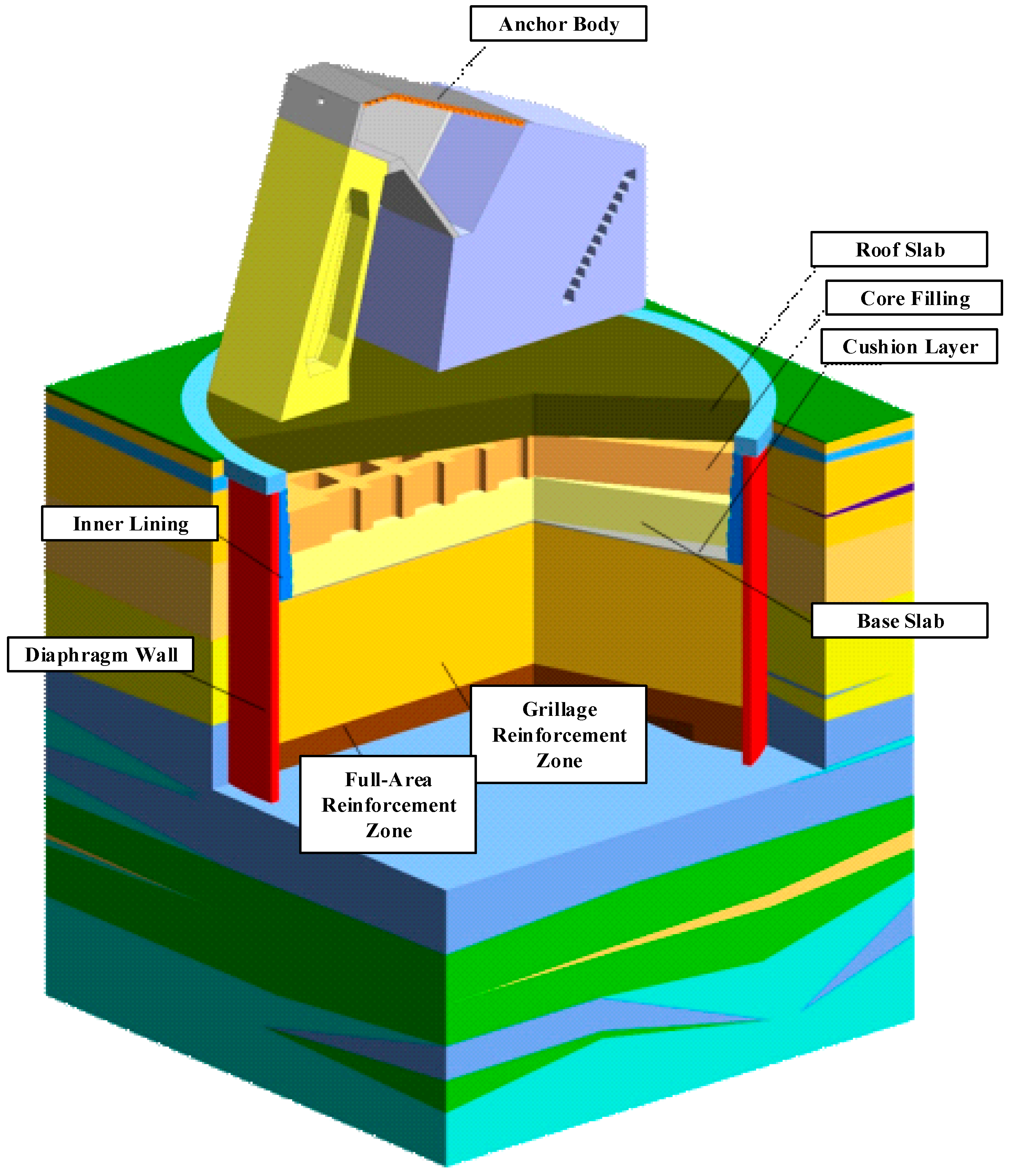
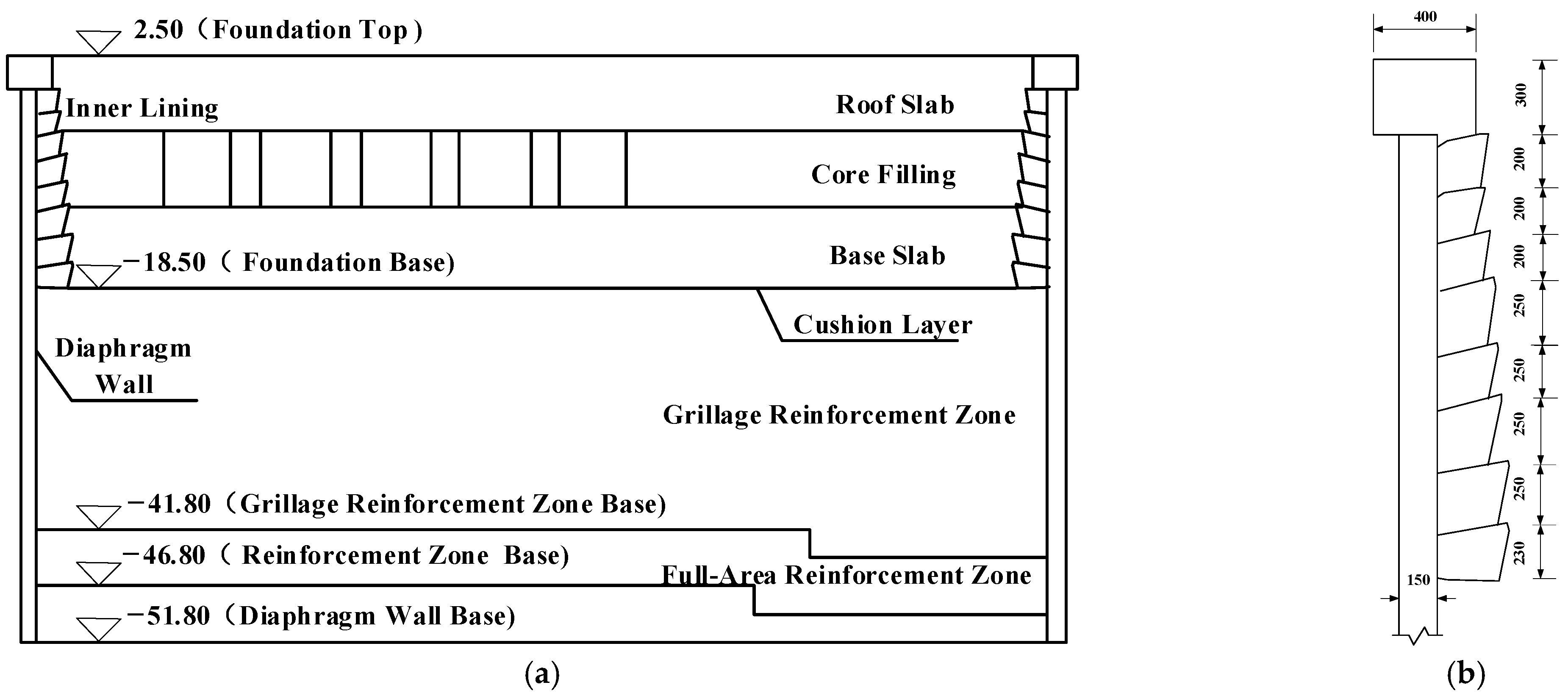
2.2. Anchorage Foundation Overview

Based on geological conditions and overall anchorage design requirements, the south anchorage foundation of the northern channel bridge employs a circular diaphragm wall with an external diameter of 90 m and a wall thickness of 1.5 m, combined with an annular reinforced concrete lining support structure (see Figure 1 for the schematic diagram and Figure 2 for structural dimensions). The foundation height is 21 m, underlain by a 0.3 m thick plain concrete cushion. The excavation depth of the foundation pit is 21.3 m, with an excavation diameter of 88.5 m. The base elevation of the pit is −18.8 m, and the top elevation is +2.5 m. Below the base lies a 28 m thick artificially treated foundation, extending to an elevation of −46.8 m. The bottom elevation of the circular diaphragm wall is −51.8 m, with an embedded depth of 32 m.

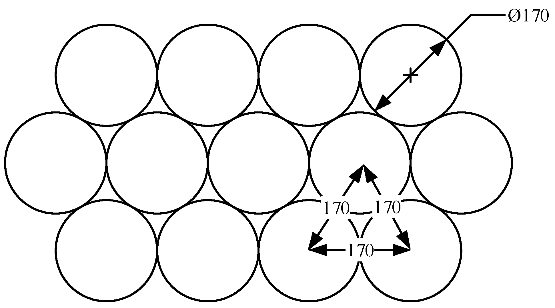
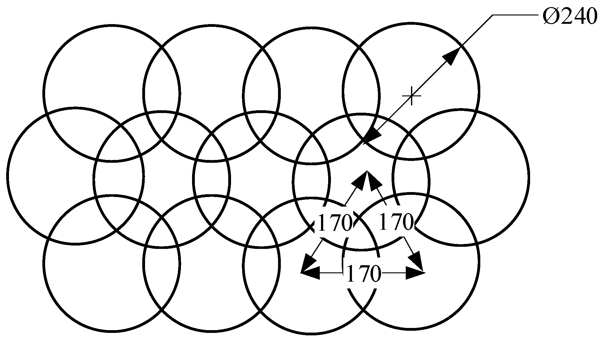
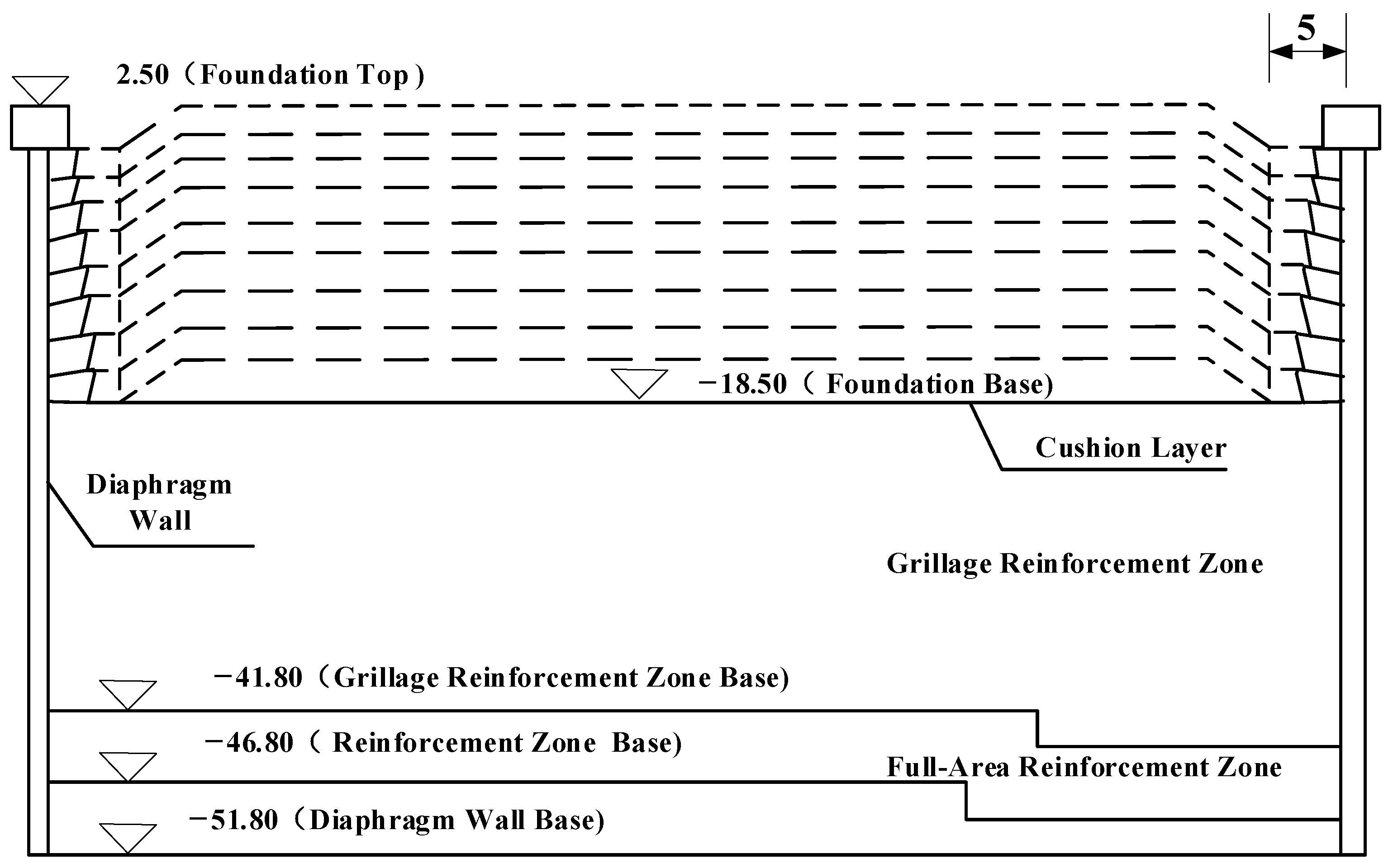
2.3. Ground Improvement Overview

The purposes of ground improvement at the pit bottom are threefold: first, to enhance the strength of the weak basal soil and reduce deformation of the diaphragm wall support structure; second, to lower the permeability of the basal soil, enabling dry excavation while ensuring anti-heave stability of the pit bottom; third, to increase the foundation bearing capacity and guarantee anti-uplift stability. Based on the comprehensive analysis of the anchorage system, the improved soil must meet three parameter requirements: 28-day-cored, unconfined compressive strength ≥ 1.8 MPa, 90-day-cored, unconfined compressive strength ≥ 2.7 MPa, and permeability coefficient ≤ 1 × 106 cm/s.
To address varying geological conditions and distinct reinforcement priorities at different depths below the base, layered and zoned reinforcement was implemented: Grid reinforcement was applied within the elevation range of −18.8 m to −44.3 m, where high-pressure jet grouting piles were arranged in a quincunx pattern with an effective pile diameter of 1.7 m, center-to-center spacing of 1.7 m, and tangent to each other; full-area reinforcement was adopted within the elevation range of −44.3 m to −49.3 m, where high-pressure jet grouting piles were also arranged in a quincunx pattern but with an effective pile diameter of 2.4 m and center-to-center spacing of 1.7 m, forming secant pile reinforcement, as shown in Figure 3 and Figure 4.

2.4. Engineering Geological Conditions

2.4.1. Topography and Geomorphology

The Zhangjinggao Yangtze River Bridge spans the Yangtze River, with its southern bank located in Daxin Town, Zhangjiagang City, and its northern bank in Shizhuang Town, Rugao City. The terrain belongs to a fluvial–marine alluvial plain. Both banks of the Yangtze River are relatively flat. The southern bank near Zhangjiagang features slightly elevated terrain in the Pingningsha area, exhibiting a south-high, north-low geomorphology. On the northern bank in Rugao, the terrain slopes gently from northwest to southeast, with the highest elevation along the middle section of the Rutai Canal. The eastern coastal area and sandbars in southern Rugao form part of the Yangtze Delta’s marine–fluvial sandbar alluvial plain.

2.4.2. Geological Conditions

The bridge site lies in a region of relatively stable tectonic activity. Geophysical surveys indicate no Holocene active faults affecting bridge construction, confirming favorable regional stability. Comprehensive analysis suggests that major nearby faults will not directly impact the project’s stability.
According to exploration data, the exposed strata consist entirely of Quaternary unconsolidated deposits. The shallow strata comprise Holocene alluvial silty clay, silt, and fine sand, underlain by Late Pleistocene medium sand and coarse sand. Based on borehole data from critical strata and pumping tests, the physical and mechanical parameters of the soil layers are summarized in Table 1.

3. Excavation Scheme

3.1. Excavation Sequence

The circular diaphragm wall foundation pit adopts a layered and partitioned top-down center island method for excavating the pit soil and constructing the inner lining. The excavation sequence is illustrated in Figure 5. The excavation proceeds in zones: At each level, the 5 m annular zone surrounding the wall is first excavated. Afterward, the inner lining is constructed to form localized rigid support. Concurrently with inner lining construction, the central zone soil is excavated to achieve spatiotemporal coupling of stepwise excavation and structural support. After the upper inner lining concrete reaches 80% of its design strength, the next layer of annular soil around the wall is excavated. The inner lining is then extended downward, repeating this cycle until reaching the final excavation level at elevation −18.8 m. This process maintains structural integrity through alternating phased excavation and sequential lining reinforcement. The excavation plan is detailed in Table 2, and the schematic is shown in Figure 5.

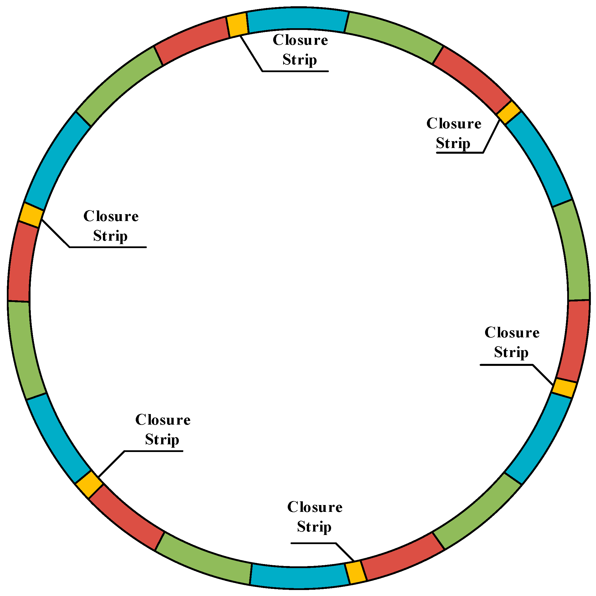
3.2. Lining Construction

The inner lining of the diaphragm wall is divided into three vertical zones from top to bottom: the first zone (0–7 m depth, 1.5 m thick, constructed in three layers of 3 m, 2 m, and 2 m), the second zone (7–14 m depth, 2.0 m thick, built in layers of 2 m, 2.5 m, and 2.5 m), and the third zone (14–21.3 m depth, 2.5 m thick, with layer heights of 2.5 m, 2.5 m, and 2.3 m). Each layer is divided into 18 planar construction units, grouped into six segments (3 units per segment), with a 2.8 m long micro-expansive concrete post-pour strip installed between adjacent segments (totaling six strips per layer, as shown in Figure 6). Vertical alignment of post-pour strips and unit joints between upper and lower layers is staggered to ensure structural integrity, as shown in Figure 7.

4. Monitoring Scheme

The prediction and control of deformation displacement, structural stress, and load distribution during foundation pit excavation, based on field monitoring data, is a vital method for dynamically managing excavation stability. During the excavation of this project, monitoring primarily focused on the following: deep horizontal displacement of the diaphragm wall, vertical displacement at the diaphragm wall top, and earth pressure.

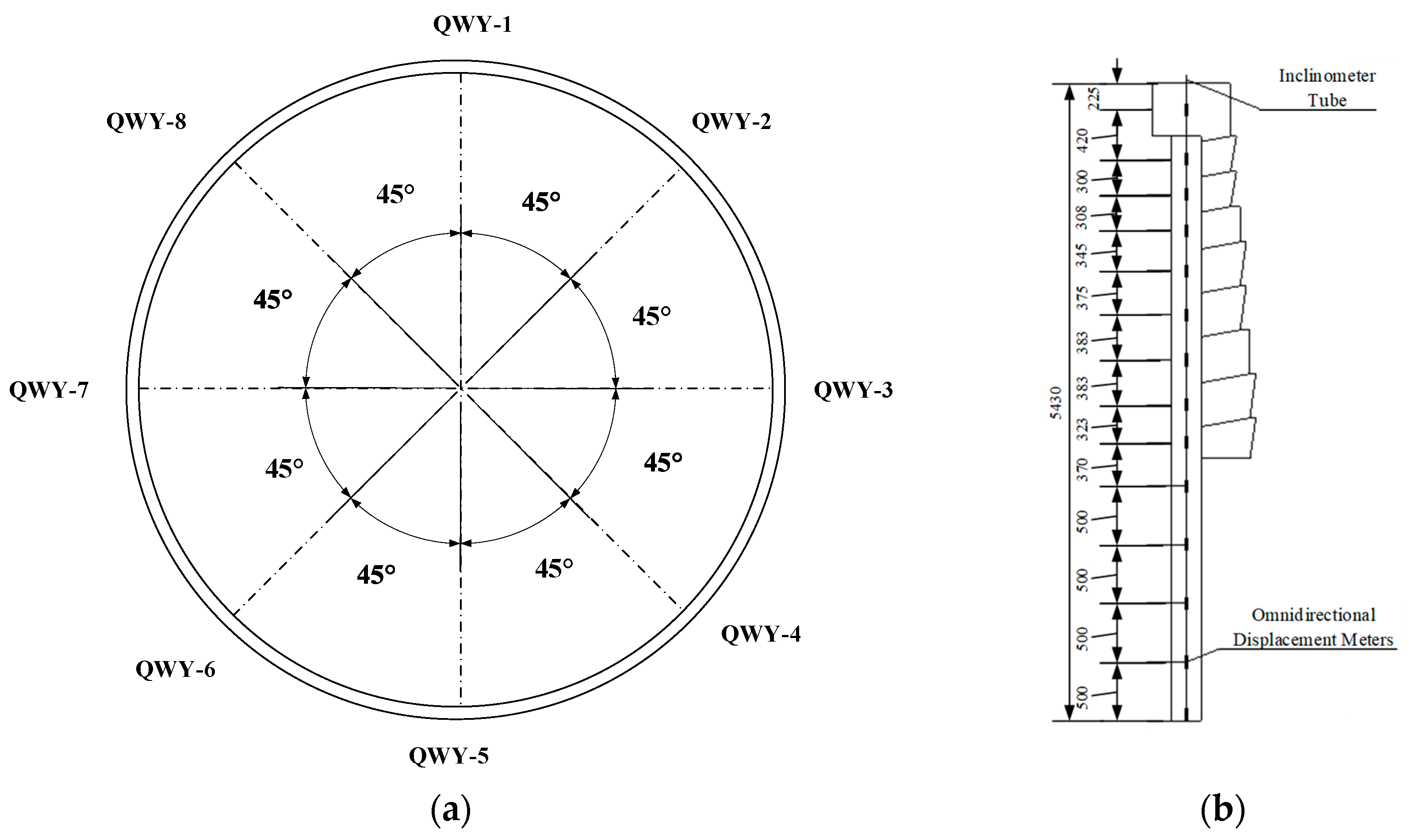
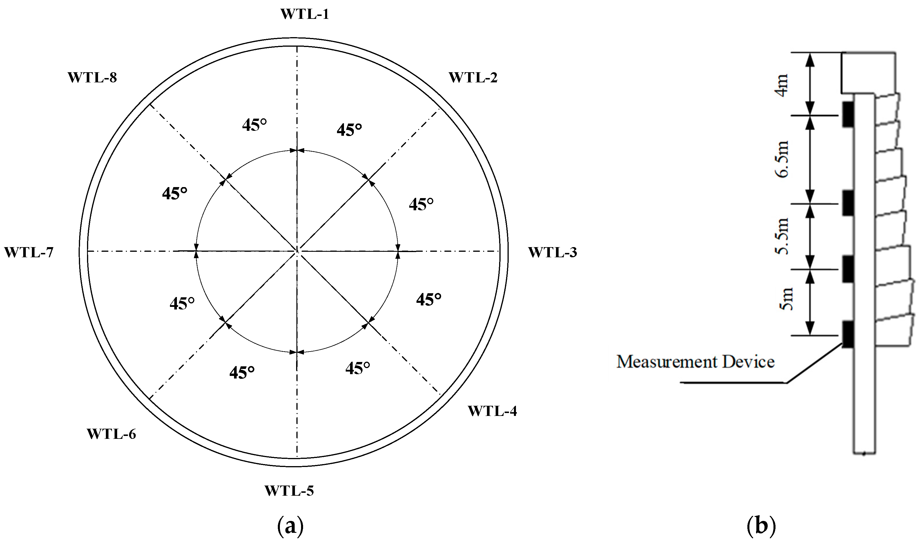
4.1. Deep Horizontal Displacement Monitoring of Diaphragm Wall

Deep horizontal displacements are measured using inclinometer tubes. Initially, 8 monitoring points (Point A series, numbered QWY-1 to QWY-8) were uniformly installed along the central axis of the diaphragm wall, embedded in the reinforcement cages of wall panels. However, due to construction errors causing inclinometer tube blockages during diaphragm wall concreting, 8 replacement displacement monitoring points (Point B series with identical numbering as Point A) were re-established 5 m outside the foundation pit perimeter. At each point, 14 omnidirectional displacement meters were installed at vertical intervals below the capping beam top: 2.25 m, 6.45 m, 9.45 m, 12.53 m, 15.98 m, 19.73 m, 23.56 m, 27.39 m, 30.62 m, 34.30 m, 39.30 m, 44.30 m, 49.30 m, and 54.30 m, as detailed in Figure 8. The omnidirectional displacement measurements were conducted using the JMQJ-1005 omnidirectional displacement meter (Jinma, Changsha, China), with a measurement accuracy of ±10 mm. This configuration maintains equivalent monitoring coverage while adapting to construction constraints through exterior relocation and multi-depth instrumentation.

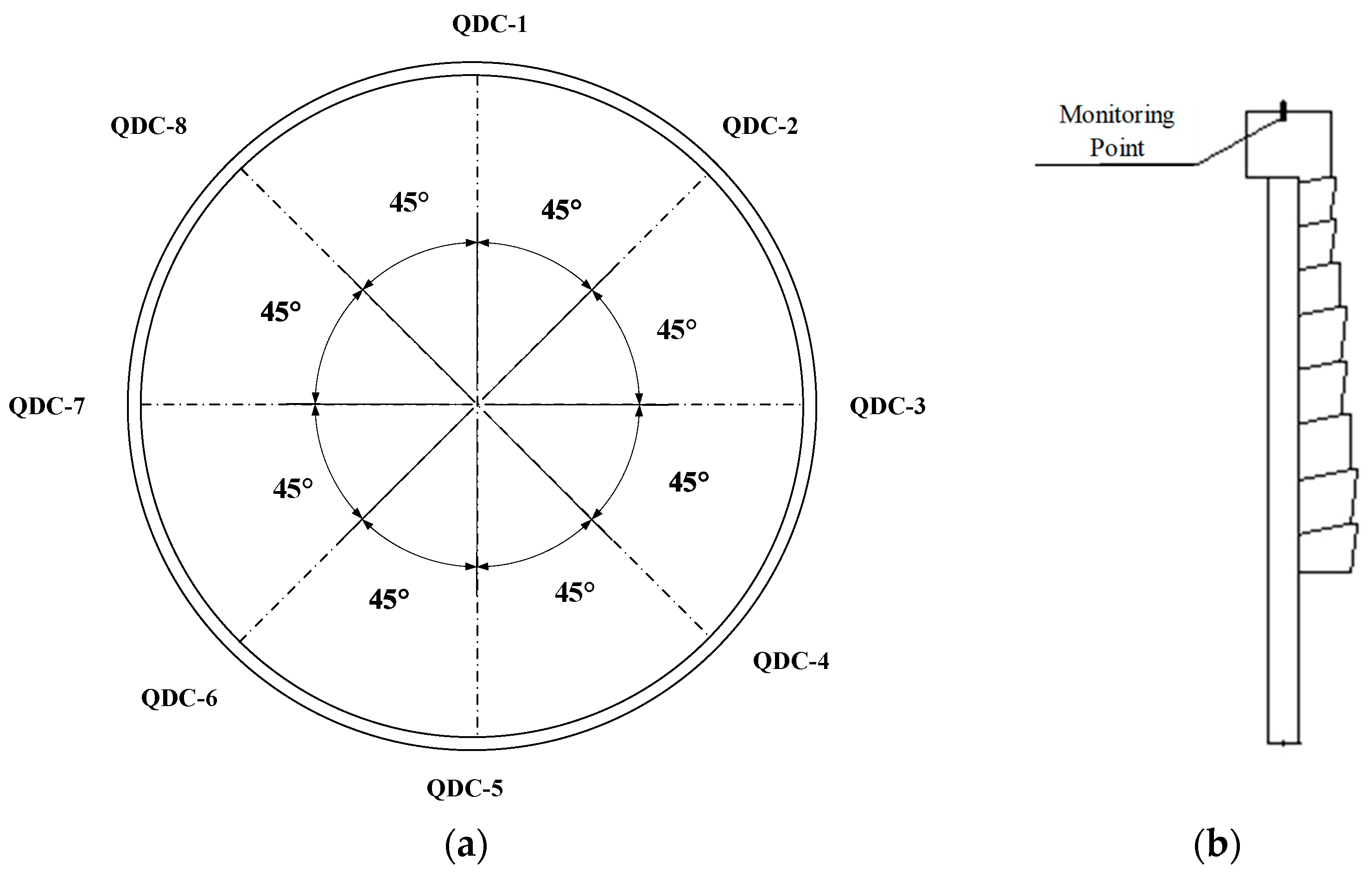
4.2. Vertical Displacement Monitoring at Wall Top

The vertical and lateral displacements at the top of the diaphragm wall are the primary components of its deformation. The magnitude of vertical displacement at the wall top directly reflects foundation pit settlement, making it a critical focus in pit engineering monitoring. Vertical displacement measurements are conducted using a total station and ancillary equipment. The total station instrument employed in this study was the TM50 high-precision smart total station (Leica, Switzerland), featuring a distance measurement accuracy of 0.6 mm + 1 ppm. This precision specification satisfies the rigorous requirements for large-scale structural displacement monitoring applications. Eight monitoring points (numbered QDC-1 to QDC-8) are uniformly distributed along the central axis of the diaphragm wall. These points are installed at the intersection between the capping beam top surface and the central axis plane of the diaphragm wall, as illustrated in Figure 9.

4.3. Earth Pressure Monitoring of Diaphragm Wall

Earth pressure monitoring for the diaphragm wall is performed using earth pressure cells. The earth pressure cell employed was the VWE model vibrating wire earth pressure cell (Geonan/GEOKON, Nanjing, China). This sensor features a measurement accuracy of 0.5% FS (Full Scale) and has passed the long-term stability certification from the Geotechnical Instrument Quality Inspection and Test Center, Ministry of Water Resources (annual drift rate < 0.1% FS), making it particularly suitable for long-term automated monitoring of soil–structure interface pressures in excavation support systems. Eight monitoring points (numbered WTL-1 to WTL-8) are uniformly distributed along the central axis of the diaphragm wall and positioned on its exterior wall surface. At each monitoring point, four measurement devices are installed vertically at intervals of 4 m, 10.5 m, 16 m, and 21 m below the capping beam top, as illustrated in Figure 10.

5. Analysis of Monitoring Results

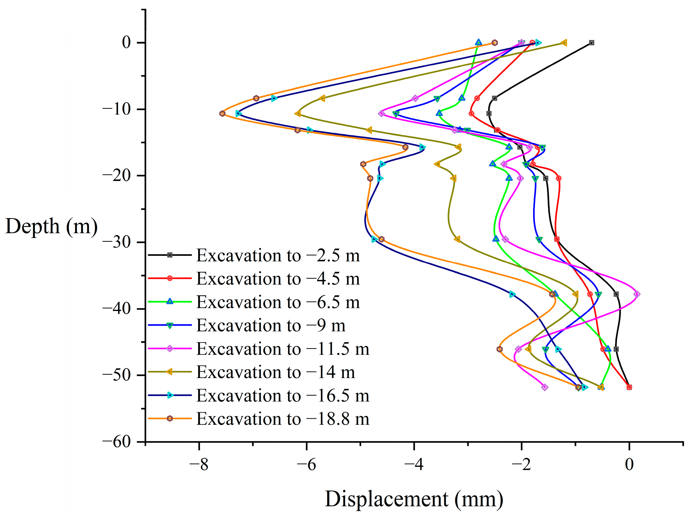
5.1. Deep Horizontal Displacement of Diaphragm Wall

Figure 11 displays the deep lateral displacement curves of a typical monitoring point QWY-7 at different excavation stages (distributed in a 270° direction). The evolution patterns of the diaphragm wall’s deep horizontal displacement during sequential excavation stages were systematically recorded by measurement devices, with the excavation stages corresponding to the sequence outlined in Table 2. In this context, positive horizontal displacement indicates outward deformation (away from the excavation pit), while negative values represent inward deformation. Since the monitoring point was not embedded within the diaphragm wall but located in the soil mass, and heavy construction machinery activity on-site significantly affected shallow lateral displacement measurements, data above −8.35 m depth were excluded. Horizontal displacement measurements at the top of the diaphragm wall were incorporated as a reference. As shown in Figure 11, the horizontal displacement at QWY-7 increased gradually during the initial excavation stages (prior to reaching −11.5 m depth) but surged significantly as excavation progressed to −16.5 m, followed by a gradual deceleration in displacement development during later stages. The displacement-depth profiles of the diaphragm wall across excavation stages exhibited consistent trends: Shallow displacements (0 m to −6.3 m) increased rapidly with depth, peaking within the −6.3 m to −10.65 m range. Below this zone, displacements attenuated sharply with depth until reaching −15.7 m, then slightly rebounded between −15.7 m and −18.25 m. From −18.25 m to −29.55 m, displacements stabilized, followed by a continued reduction until reaching a minimum at −37.8 m. Displacements then increased again from −37.8 m to −46.5 m before gradually diminishing toward zero below −46.5 m.
Based on the structural dimensions of the circular diaphragm wall shown in Figure 2, the analysis of Figure 11 reveals that during initial excavation stages, maximum displacement occurs near the excavation face. This aligns closely with the finding of Yan et al. [40] that peak displacement depth lies approximately 0.35 m below the actual excavation level. However, Yan et al. [40] also reported progressive downward migration of maximum lateral displacement with excavation depth—a phenomenon not observed in this study where as excavation deepened, the peak displacement location did not migrate downward.
Shi et al. [41] demonstrated that effective basal restraint maintains near-constant displacement at the wall base, consistent with our observations: the high-stiffness reinforcement zone restricted displacement development near the pit bottom (−18.8 m), while simultaneously explaining rapid displacement attenuation between −10.65 m and −15.7 m. Stable displacements from −18.25 m to −29.55 m are attributed to uniform earth pressure distribution within the reinforcement zone due to its substantial global stiffness. Below −29.55 m, displacements further diminish owing to stronger constraints imposed by the full-area improvement zone (compared to the grillage reinforcement zone) on the diaphragm wall.
According to the Technical Standard for Monitoring of Building Foundation Pit Engineering (GB 50497-2019) [20,42], the warning thresholds for diaphragm wall deep horizontal displacement monitoring of Grade I foundation pit in soils are listed in Table 3. For the circular diaphragm wall foundation pit of the South Anchorage of the Zhangjinggao north channel bridge, with an excavation depth of 21.3 m, the control standard for deep horizontal displacement is set at 30 mm. Based on field monitoring data, the maximum deep horizontal displacement of the diaphragm wall in this project meets the control criteria. Therefore, the circular diaphragm wall provided sufficient lateral deformation protection during the excavation process.

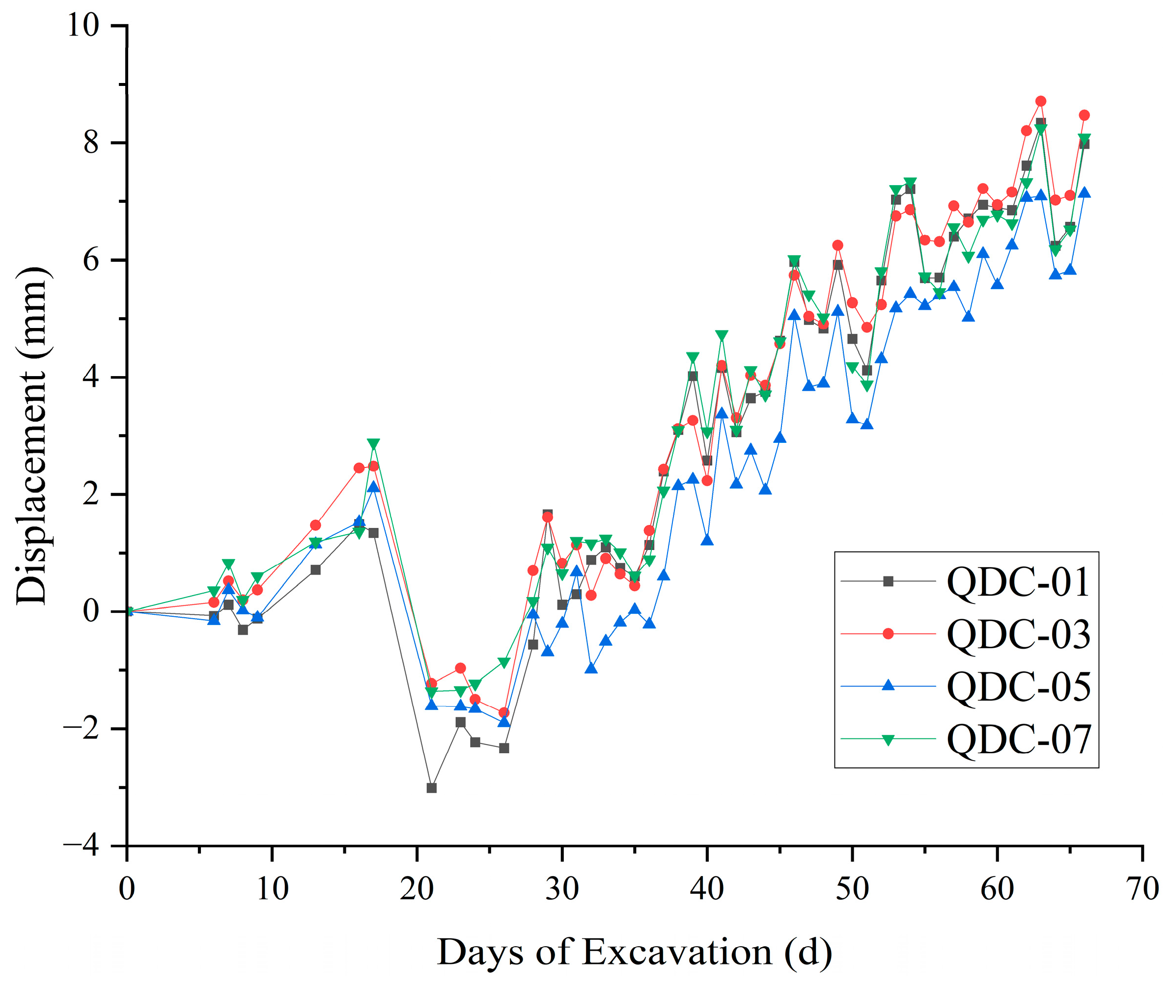
5.2. Vertical Displacement of Diaphragm Wall Top

Figure 12 presents four typical monitoring points (QDC-1, QDC-3, QDC-5, and QDC-7, located at 0°, 90°, 180°, and 270° orientations), systematically documenting the evolutionary patterns of vertical displacement at the wall top throughout the entire excavation period of the foundation pit. As shown in Figure 12, during the initial excavation phase, the wall top exhibited uplift displacement, with a maximum uplift of +3 mm (at monitoring point QDC-5), attributed to soil unloading rebound caused by shallow excavation in the soft soil area. Between 17 and 21 days, the wall top began to settle, reaching a maximum settlement of approximately −3 mm (at QDC-1). Subsequently, the wall underwent multiple “increase–decrease” cycles in the vertical direction but displayed an overall upward fluctuating uplift trend. The maximum uplift of 8 mm occurred after the completion of pit excavation.
Based on the excavation sequence (Table 2) and inner lining configuration (Figure 2), the vertical displacement evolution in Figure 12 is attributed to multi-phase soil–structure interactions. Initial shallow excavation (0–8 d) induced +3 mm uplift (QDC-5) due to soil unloading rebound, and was amplified by localized 5 m range soil removal prior to first-layer lining placement. Subsequent first-layer lining casting (8–10 d) increased structural self-weight, slightly suppressing displacement. Second-phase excavation (10–17 d) within the first lining zone triggered renewed rebound (−3 mm settlement at QDC-1). The 17–21 d transition to settlement reflects combined effects of second-layer lining loading and dewatering-induced pore pressure dissipation, consistent with Terzaghi’s principle: reduced groundwater levels elevated effective stresses, driving recompression of over-consolidated clays. The final 8 mm uplift post-excavation demonstrates the dominance of cumulative soil rebound over structural constraints, highlighting the soil vertical displacement mechanisms due to joint effects of foundation pit excavation and foundation pit dewatering in soft soil environments.
According to Table 3, the allowable vertical displacement for the diaphragm wall is 10 mm. The maximum measured vertical deformation on-site is approximately 8 mm, equivalent to 0.04% of the excavation depth (H), which complies with the control criteria.

5.3. Earth Pressure on Diaphragm Wall

Figure 13 illustrates the earth pressure distribution at different depths of monitoring point WTL-1 along the diaphragm wall during various excavation stages, compared with the at-rest earth pressure and Rankine active earth pressure. According to Figure 13, for monitoring point WTL-1, at the −1.5 m depth, the earth pressure exceeded the at-rest earth pressure throughout all excavation stages. For the −8 m depth, the measured earth pressure values were sparse due to equipment issues but generally aligned with the at-rest earth pressure limit. However, for the −13.5 m depth, the earth pressure was approximately distributed near the active earth pressure, with some stages slightly lower than the active earth pressure. At the −18.5 m depth, the earth pressure ranged between the at-rest and active earth pressure, with some measurements slightly below the passive–active earth pressure. As excavation progressed, earth pressures at all depths initially decreased and then gradually increased. The −1.5 m depth exhibited abnormally large and irregular measurements due to soil disturbance from construction. At the −13.5 m depth, the earth pressure during initial excavation stages fell below the Rankine active earth pressure limit. When excavation reached −16.5 m, the pressure approached the Rankine active limit but showed minimal changes with further excavation. At the −18.5 m depth, the earth pressure initially aligned with the at-rest earth pressure. Upon reaching −6.5 m excavation depth, it approached the Rankine active limit, subsequently decreasing before gradually converging toward this limit with continued excavation.
In summary, the earth pressures at different depths of the diaphragm wall generally followed a pattern of transitioning from at-rest earth pressure toward Rankine active earth pressure during early excavation stages. However, the high-pressure jet grouting pile reinforcement at the pit bottom significantly enhanced the embedment effect of the lower diaphragm wall. This restraint limited wall deformation and redistributed external earth pressures, leading to temporarily lower-than-active earth pressure values during intermediate excavation phases. As excavation advanced, progressive wall deformation allowed earth pressures to gradually realign with the Rankine active earth pressure.

6. Stability Analysis

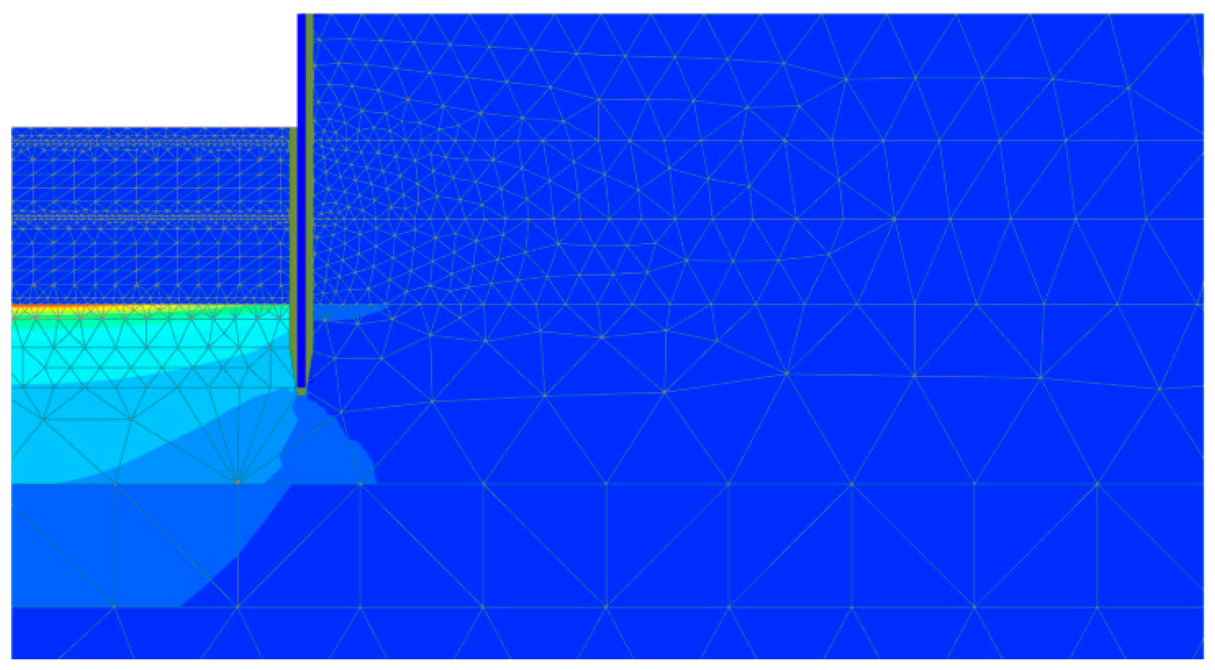
6.1. Finite Element Model Development

Finite element modeling of the excavation was performed using PLAXIS 2D. Based on axisymmetric simplification principles, a two-dimensional finite element model was established along the centerline of the excavation pit with half of the actual structure. To mitigate boundary effects, the model dimensions were set at 250 m × 150 m [43]. Key geometric parameters included the following: excavation depth H = 21.3 m, retaining wall embedment depth D = 33 m, and excavation radius B = 45 m. Boundary conditions were assigned as follows: horizontal displacements were restrained at both lateral boundaries, full fixation was applied at the bottom boundary, and the top boundary remained free. Due to symmetry, the left boundary was designated as impermeable while the right boundary was permeable; the bottom boundary was also impermeable. Soil strata were modeled using solid elements, while the retaining wall was simulated with plate elements.
To simulate the interaction between the diaphragm wall and the soil, the parameter Rinter is used [44]. The parameter Rinter reflects the degree of interaction between the two. The default value of Rinter in the PLAXIS 2D, 0.67, was adopted [45].
The soil body adopts the Mohr–Coulomb constitutive model. The Mohr–Coulomb constitutive model parameters for each soil layer were obtained based on the site geological investigation report and indoor geotechnical tests, including triaxial consolidated drained loading/unloading tests, triaxial consolidated drained shear tests, and standard consolidation tests. To simplify the model, selected geologically similar soil strata were merged into identical layers, as presented in Table 4.
The reinforcement zone adopts the Mohr–Coulomb constitutive model. The equivalent elastic modulus of the reinforced composite, as well as the equivalent angle of internal friction and equivalent cohesion used as the Mohr–Coulomb constitutive model parameters for the reinforced composite, were calculated based on jet grouting column parameters and undisturbed soil parameters [46].
The model was discretized using triangular elements. The mesh parameter settings employed the ‘Medium’ mesh generation accuracy in the PLAXIS 2D (V2024), and local refinement was applied to the diaphragm wall and the reinforcement zone.
To accurately simulate the mechanical behavior of the anchorage foundation in actual construction sequences, this analysis accounts for the construction of the diaphragm wall, cap beam, and deep ground improvement, along with staged excavation and dewatering of the foundation pit. Corresponding calculation phases were established as follows: (1) initial geostatic stress equilibrium; (2) construction of diaphragm wall, cap beam, and deep ground improvement; (3) excavation with concurrent construction of 1st inner lining layer and dewatering to pit bottom; (4) excavation and construction of 2nd inner lining layer; (5) excavation and construction of n-th inner lining layer (n ≤ 8).

6.2. Mechanism of Foundation Pit Heave

In PLAXIS 2D (V2024), the hydraulic uplift deformation mechanism of the foundation pit without reinforcement was obtained through safety analysis using the Strength Reduction Method, Figure 14 and Figure 15 illustrate the deformation mechanisms of hydraulic uplift in the foundation pit without ground improvement. Volumetric strain primarily occurs at the upper surface of the water-bearing sand layer below the base (see Figure 14). Significant shear strain is also observed at the same location (see Figure 15). The maximum strain occurs at the center of the pit base and gradually decreases with increasing distance from the center. It can be concluded that the sand is suspended on the upper surface under hydraulic uplift, which is governed by volumetric strain. As shown in Figure 15, the maximum shear strain occurs at the base surface and the soil–wall interface. This indicates that the resistance to hydraulic uplift of the overlying soil mass primarily depends on the shear strength of the soil at the soil–wall interface.
Figure 16 illustrates the heave and shear failure of the confined aquifer at the pit base when excavation reaches −16.5 m. Volumetric strain penetrates the entire interface between the overburden soil and the confined aquifer, diminishing radially from the center to the periphery (see Figure 16), indicating non-uniform uplift of the overburden under artesian pressure. Figure 17 reveals that the orientation of effective principal stresses at the soil–wall interface aligns at approximately 45° relative to the local horizontal and vertical directions, confirming shear failure in the soil mass. Figure 18 depicts the total horizontal strain distribution in the overburden, where dominant tensile strain initiates at the lower interface between the confined aquifer and the diaphragm wall, with progressive crack propagation toward the pit base and soil–wall interface over time. Figure 19 identifies dual failure modes: (1) central heave-induced water ingress due to tensile failure at the overburden base from differential uplift; (2) shear rupture along the soil–wall interface, driven by exceeding the shear strength of the soil.

6.3. Stability Against Hydraulic Uplift Calculation

For deep foundation pits involving confined aquifers beneath the excavation base, the results of stability against hydraulic uplift verification directly determine the water level in the dewatering wells of the confined aquifer, thereby indirectly influencing the development of ground settlement outside the pit. Consequently, stability against hydraulic uplift verification is critical not only for base safety but also for controlling ground settlement. Overly conservative stability calculations may lead to excessive ground settlement, potentially causing building tilt or cracking, which violates environmental protection requirements for surrounding areas. Conversely, overly risky calculations may compromise safety and are equally unacceptable. By analyzing the failure mechanisms derived from finite element simulations, this section introduces the standardized method for stability against hydraulic uplift analysis and proposes an improved approach that accounts for the shear strength of the overlying soil at peripheral interfaces.
For foundation pits with confined aquifers underlying the base, current codes mandate stability verification using the pressure equilibrium method, as illustrated in Figure 20. The safety factor against hydraulic uplift ( F sl ) is defined as the ratio of the overburden soil weight (resistance) to the confined aquifer’s water pressure (load):
F sl = γ sat H p w
In the formula:
γ sat is the saturated unit weight of the soil overlying the confined aquifer (kN/m3); H is the effective embedment depth of the retaining structure above the confined aquifer’s upper boundary. If the retaining structure does not penetrate into the confined aquifer, this parameter is adjusted to include the vertical distance between the retaining structure’s base and the confined aquifer’s top surface. p w is hydraulic pressure exerted by the confined aquifer (kPa), calculated as p w = γ w H w , where γ w is the unit weight of water and H w is the piezometric head. p crl is the critical hydraulic pressure, representing the threshold for hydraulic uplift failure instability, which is derived as p crl = γ sat H .
To address the limitations of the code-prescribed method, this study proposes an improved calculation approach that incorporates the contribution of side shear resistance in the soil mass against hydraulic uplift, based on the standardized formula. A similar method for considering the contact shear strength between soil and support structures has been validated in Sun [47]’s research. Based on this method, a global uplift stability analysis framework for foundation pits with confined aquifers is developed. The method treats the soil mass against hydraulic uplift as an integral body for force equilibrium analysis, assuming the pit reaches a critical state when forces balance:
F + G P = 0
In the formula: F represents the shear strength contribution of the surrounding soil around the zone against hydraulic uplift; G represents the total weight of the overburden soil above the confined aquifer’s top surface within the pit; P represents the confined water pressure.

6.4. Base Heave Mechanism of Foundation Pit

In the PLAXIS 2D (V2024), the heave deformation mechanism of the foundation pit after reinforcement was analyzed using the Strength Reduction Method for safety assessment, as illustrated in Figure 21 and Figure 22. Figure 21 shows the vertical displacement cloud map of the in-pit soil under hydraulic uplift failure. From Figure 21, it is observed that the vertical displacement is larger in the central area of the pit but smaller near the diaphragm wall interface while the foundation pit experienced base heave failure, which is same as the deformation mechanisms of the foundation pit without reinforcement. Figure 22 presents the incremental displacement cloud map of the soil under base heave failure. Figure 22 clearly reveals the heave failure mechanism and the external soil slip surface, where sliding occurs at the base of the diaphragm wall. This indicates that the failure mode is heave failure rather than hydraulic uplift failure, which significantly differs from the failure mechanism without reinforcement.
By analyzing the failure mechanisms derived from finite element simulations and based on Terzaghi’s bearing capacity model for anti-heave stability verification [31]—which considers soil weight, cohesion, and surcharge load as components of shallow foundation bearing capacity—this study proposes an improved stability against base heave verification method. The schematic diagram of this method is shown in Figure 23. The study by Yin et al. [3] demonstrated that ground improvement effectively enhances anti-heaving stability—a conclusion similarly applicable to the foundation reinforcement methodology employed in this research. Due to ground improvement, the soil layer below the pit base within the reinforced zone has been significantly strengthened. Consequently, soil sliding occurs at the base of the diaphragm wall support. Moreover, since the high-pressure rotary jet grouting reinforcement exhibits enhanced shear resistance, the calculation should emphasize the contribution against base heave generated by this reinforced zone.

7. Conclusions

The study on the foundation pit excavation for the south anchorage of the Zhangjinggao Yangtze River Bridge north channel bridge demonstrates that employing high-pressure jet grouting pile technology to create an artificial composite foundation in soft soil layers—with permeability coefficients, bearing capacity, and base friction coefficients meeting design requirements—effectively enhances the engineering properties of the anchorage foundation. This approach not only increases the strength of the base soil to restrict diaphragm wall deformation but also simultaneously improves permeability characteristics and aquitard thickness, achieving coordinated enhancement against hydraulic uplift failures. Furthermore, it enhances the foundation’s shear resistance, thereby ensuring anti-base heave stability of the excavation, ultimately improving project safety and stability. This study fills a critical research gap in the application of high-pressure jet grouting technology for deep ground improvement in anchorage foundation pit engineering. It not only provides an innovative solution for ultra-deep excavations in complex geological environments but also establishes a robust technical foundation for advancing jet grouting methodologies in future foundation pit projects. This study concludes the following key findings:
(1)
During the final excavation stage, the maximum horizontal displacement developed within the circular diaphragm wall and concrete lining system. Simultaneously, the peak vertical displacement at the wall crown reached approximately 0.04% of the excavation depth. Both displacement metrics remained substantially below the code-specified control limits, demonstrating that the circular diaphragm wall and lining system effectively controlled pit deformation and ensured construction safety.
(2)
The earth pressure on the diaphragm wall exhibits a “decrease followed by increase” pattern during excavation. Initially, it transitions from at-rest earth pressure toward Rankine active earth pressure. However, the high-pressure jet grouting pile reinforcement at the pit bottom significantly enhances the embedment effect of the lower diaphragm wall, constraining deformation and redistributing earth pressures. This mechanism leads to temporary lower-than-active earth pressure values during intermediate excavation phases. As excavation progresses, progressive wall displacements enable gradual convergence with the theoretical Rankine active earth pressure limit.
(3)
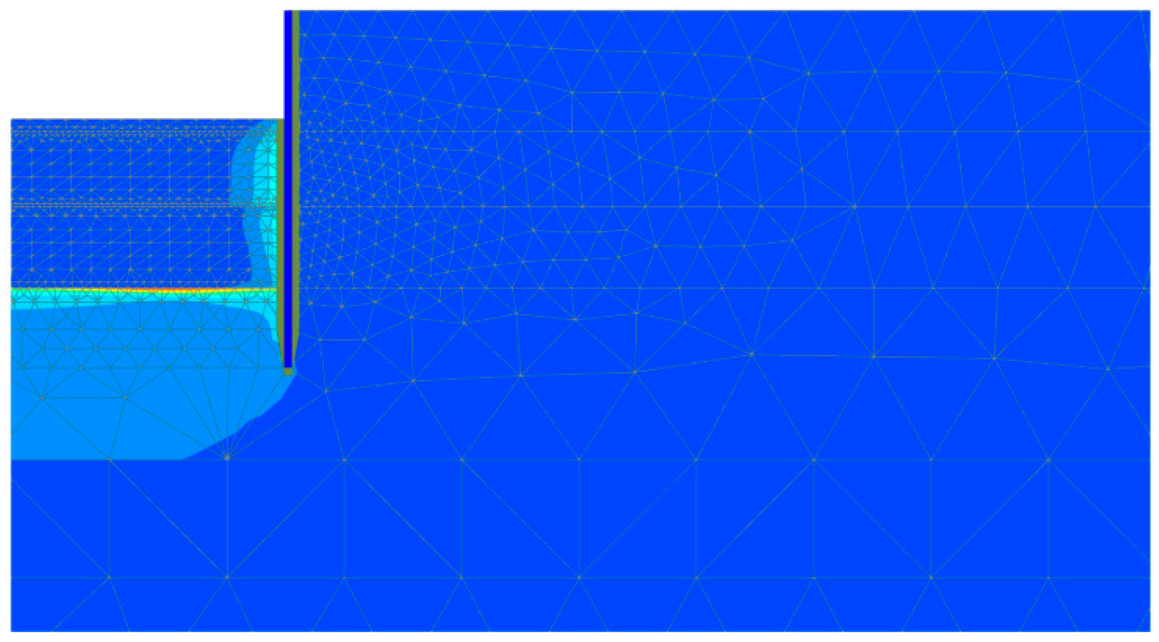
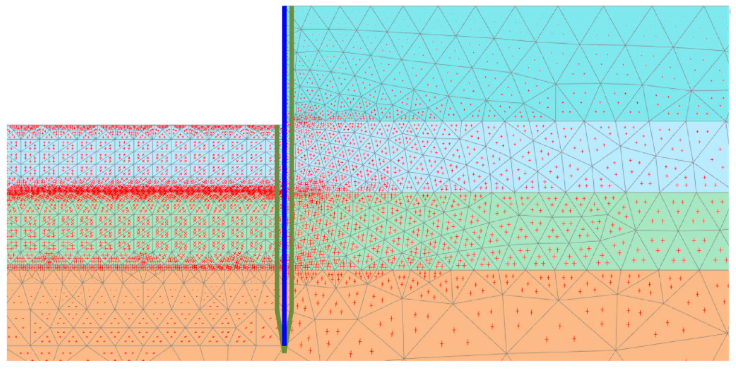
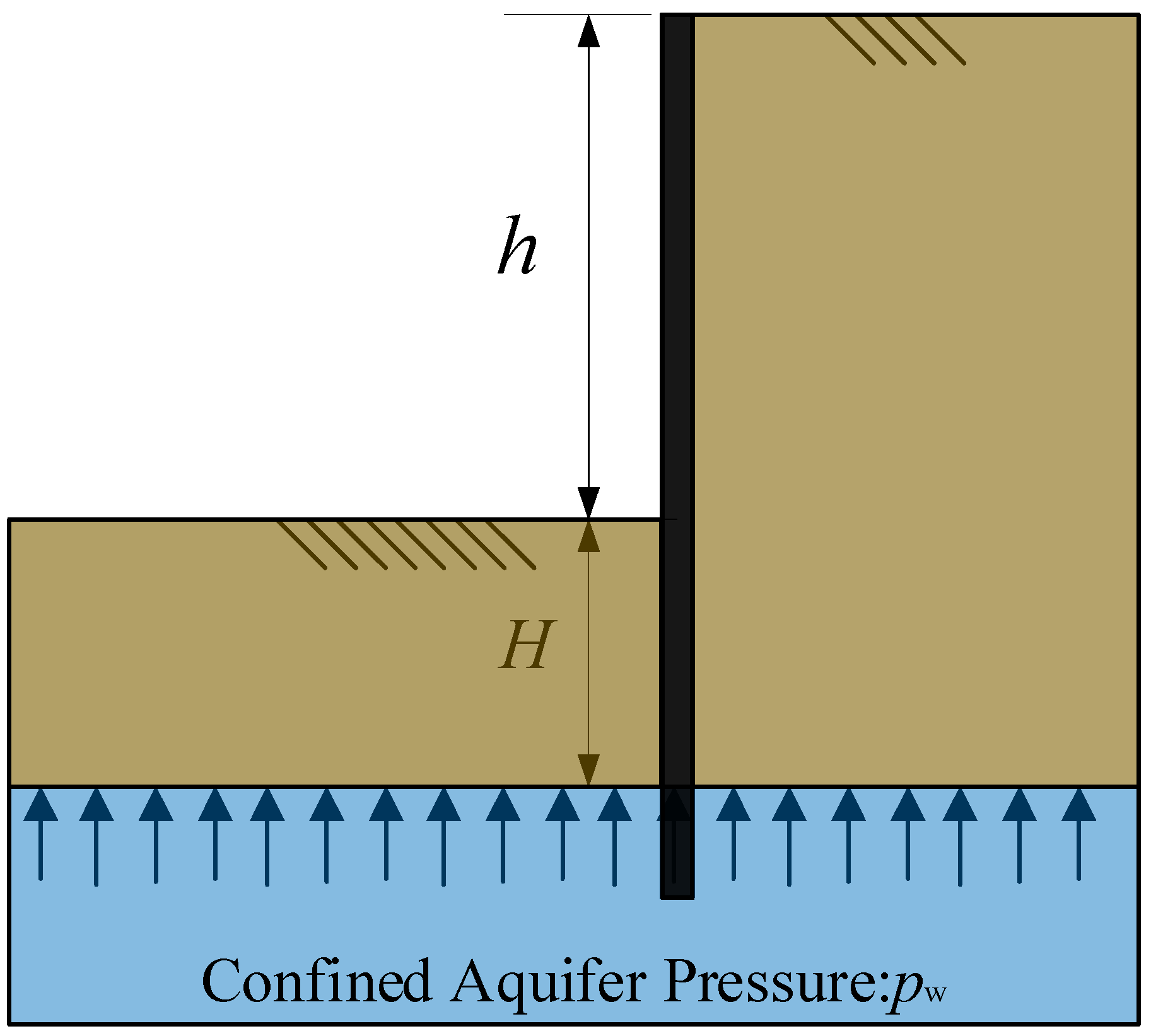
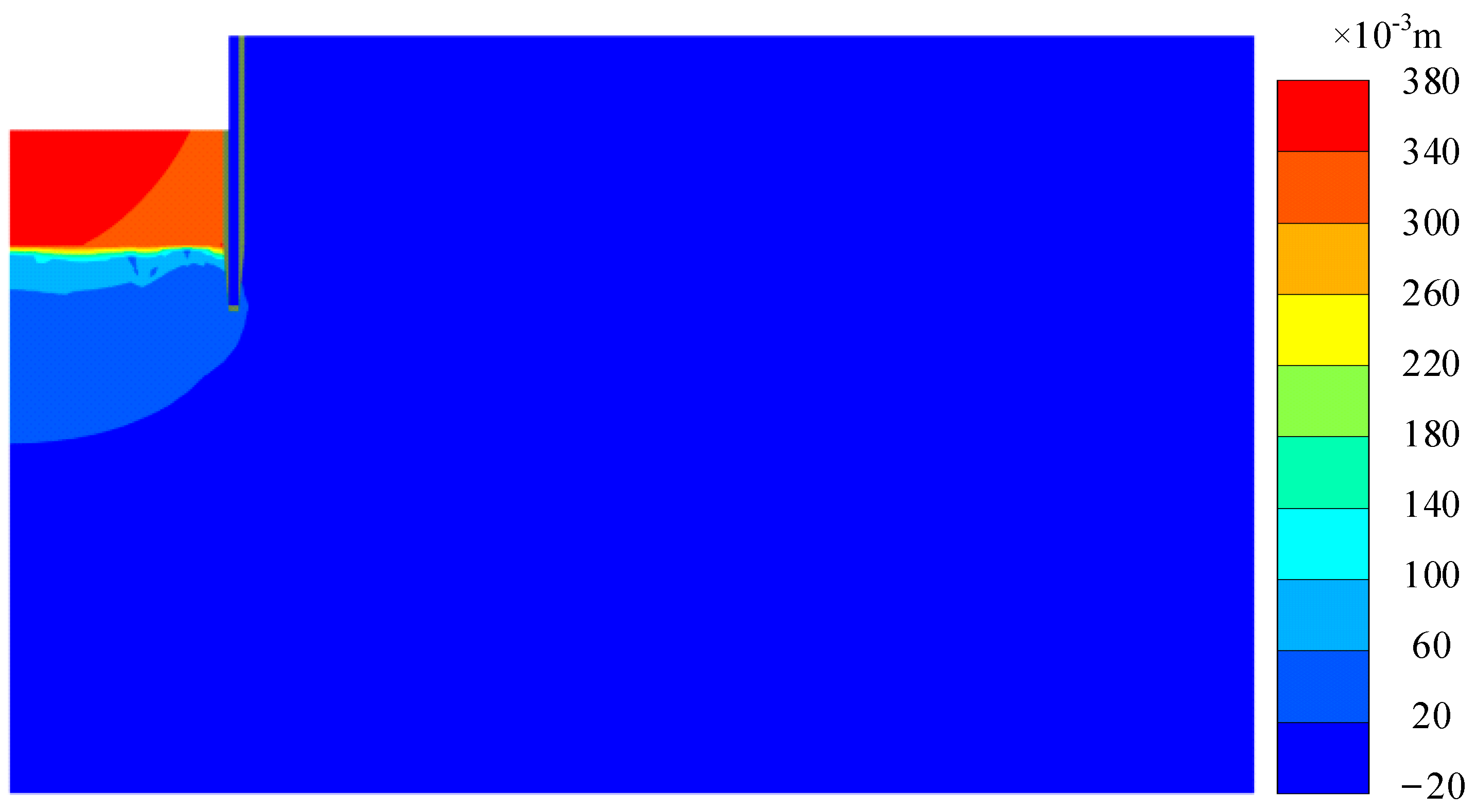
The finite element simulation of the unreinforced excavation base revealed a distinct failure mechanism: confined aquifer water pressure induces sand particle suspension, triggering central heaving of overburden soil and interface shear failure along the soil–wall boundary. This failure mechanism confirms that the shear strength of ground improvement can effectively counter hydraulic uplift. The proposed calculation methodology, which incorporates the mobilization of side shear strength in the anti-uplift soil mass based on code-specified formulas, is particularly suitable for deep reinforcement techniques that enhance soil shear properties.
(4)
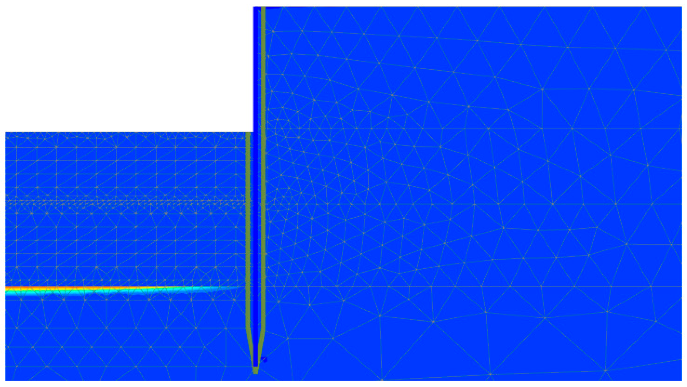
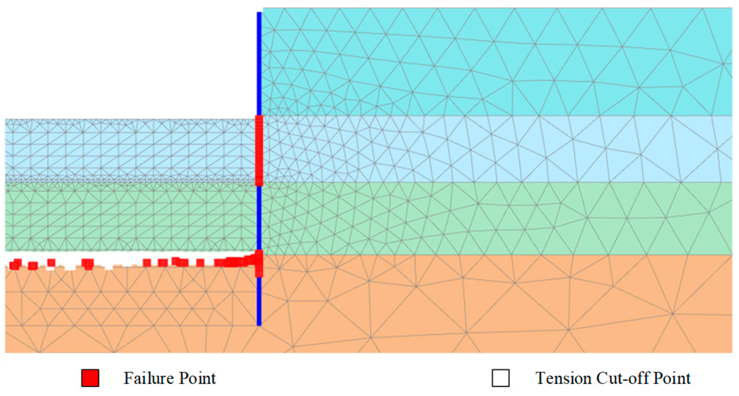
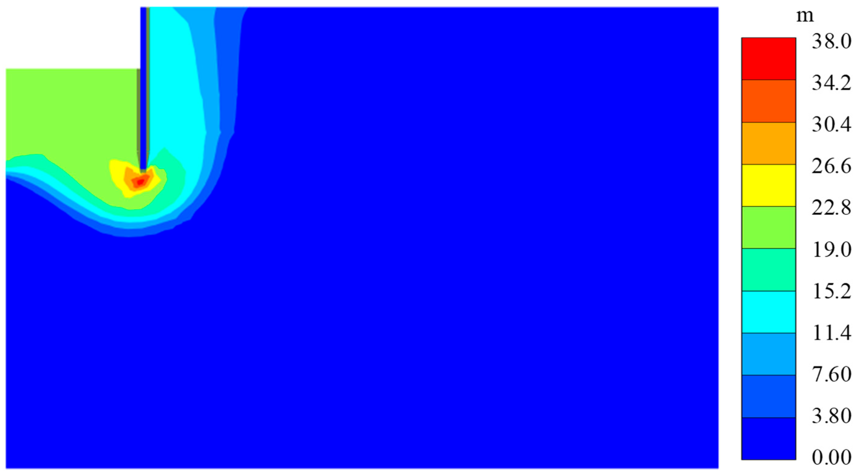
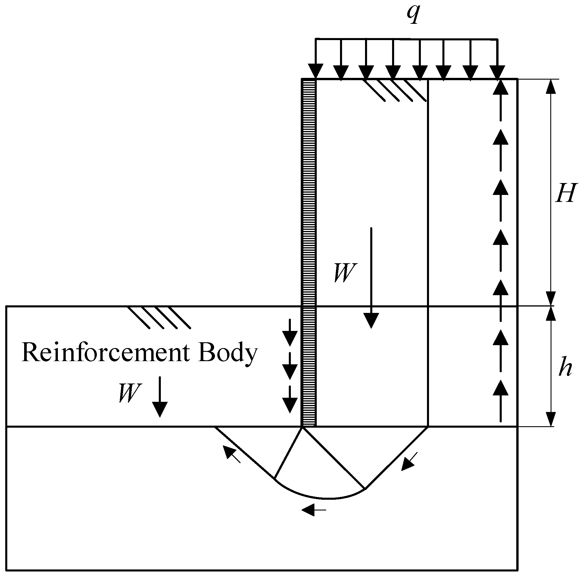
In the finite element model simulating the reinforced pit base, the soil failure mechanism of central uplift of the overburden soil layer and sliding shear failure in the external soil adjacent to the diaphragm wall demonstrate that ground improvement changes the soil failure mechanism of the pit base. The calculation method based on Terzaghi’s bearing capacity model for anti-heave stability verification, which accounts for the mobilization of side shear strength in the overburden soil, is better suited for deep reinforcement techniques that improve soil shear performance.
This study did not conduct long-term monitoring, and the Mohr–Coulomb constitutive model adopted in the numerical analysis, while commonly used in engineering practice, cannot capture the creep behavior of soft soils. Future studies should adopt long-term monitoring and validated advanced soil–structure interaction models to consider the creep effects of soft soils for the improvement in prediction accuracy. In addition, in-depth research will be conducted on how factors such as soil improvement at the excavation bottom, different physical and mechanical properties of soft clay, and critical construction sequences interact with one other and ultimately influence the deformation behavior mechanisms of the excavation support structures, aiming to significantly enhance deformation control and overall project safety.

Author Contributions

Conceptualization, X.Z., W.Z. (Wenqing Zhao) and G.D.; methodology, X.Z., W.Z. (Wenqing Zhao) and Z.C.; software, W.Z. (Wenqing Zhao), J.Z., R.J., Z.C. and W.Z. (Wenbo Zhu); validation, W.Z. (Wenqing Zhao), J.Z., R.J., Z.C. and W.Z. (Wenbo Zhu); formal analysis, X.Z. and W.Z. (Wenqing Zhao); investigation, X.Z. and W.Z. (Wenqing Zhao); resources, X.Z.; data curation, X.Z., W.Z. (Wenqing Zhao) and G.D.; writing—original draft preparation, X.Z., W.Z. (Wenqing Zhao), G.D., J.Z., R.J., Z.C. and W.Z. (Wenbo Zhu); writing—review and editing, X.Z., W.Z. (Wenqing Zhao), G.D., J.Z., R.J., Z.C. and W.Z. (Wenbo Zhu); visualization, X.Z., W.Z. (Wenqing Zhao), J.Z. and R.J.; supervision, X.Z., W.Z. (Wenqing Zhao), G.D., J.Z., R.J., Z.C. and W.Z. (Wenbo Zhu); project administration, X.Z., G.D., J.Z., R.J., Z.C. and W.Z. (Wenbo Zhu); funding acquisition, X.Z. and G.D. All authors have read and agreed to the published version of the manuscript.

Funding

This research was funded by the National Natural Science Foundation of China (52378328, 52208333), Research Fund for Advanced Ocean Institute of Southeast University (Key Program KP202404; General Program GP202403), and the Scientific & Technological Research and Development Project of Road & Bridge International Co., Ltd. (RP2023018895).

Institutional Review Board Statement

Not applicable.

Informed Consent Statement

Not applicable.

Data Availability Statement

The raw data supporting the conclusions of this article will be made available by the authors on request.

Acknowledgments

The authors sincerely appreciate the valuable contributions of the editors and reviewers of this work. We extend our gratitude to the editorial team for their professional guidance and efficient coordination throughout the publication process. Our special thanks go to the anonymous reviewers for their meticulous evaluation, constructive feedback, and insightful suggestions, which significantly strengthened the rigor and clarity of this manuscript. Their expertise and dedication have been instrumental in refining both the technical content and the presentation of this research.

Conflicts of Interest

Authors Xiaoliang Zhu and Junchen Zhao were employed by the company Road & Bridge International Co., Ltd. The remaining authors declare that the research was conducted in the absence of any commercial or financial relationships that could be construed as a potential conflict of interest.

References

  1. Ge, C.H.; Yang, M.; Li, P.F.; Zhang, M.J. Influence of deep foundation pit excavation on surrounding environment: A case study in Nanjing, China. Acta Geophys. 2025, 73, 495–516. [Google Scholar] [CrossRef]
  2. Lin, G.; Lin, Z.R.; Zhao, Y.; Xu, C.J.; Sun, F.; Duan, Y.; Fang, T. Force and Deformation Characteristics of Large-Scale Zoning Excavation in Soft Soil: A Case Study in Hangzhou. Appl. Sci. 2024, 14, 6358. [Google Scholar] [CrossRef]
  3. Yin, S.Y.; Yang, Z.; Lu, C.T.; Dang, Y.K. Numerical Investigation of Underlying Curved Tunnel Heave during a New Foundation Pit Excavation. Int. J. Geomech. 2024, 24, 04024132. [Google Scholar] [CrossRef]
  4. Huang, J.Z.; Liu, J.Z.X.; Guo, K.; Wu, C.; Yang, S.; Luo, M.X.; Lu, Y.N. Numerical Simulation Study on the Impact of Deep Foundation Pit Excavation on Adjacent Rail Transit Structures-A Case Study. Buildings 2024, 14, 1853. [Google Scholar] [CrossRef]
  5. Wang, C.; Li, G.; Zou, S.; Yin, S.; Wang, S.; Xiao, Y.; Yu, Z. Intelligent Monitoring and Early Warning System for Deep Foundation Pit of Construction Site Based on Digital Twinning Process, Has Threshold Management Module Used as Early Warning Algorithm Corresponding to Deep Foundation Pit. CN113404029-A, 17 September 2021. [Google Scholar]
  6. Tan, Y.; Wang, D.L. Structural Behaviors of Large Underground Earth-Retaining Systems in Shanghai. I: Unpropped Circular Diaphragm Wall. J. Perform. Constr. Facil. 2015, 29, 04014058. [Google Scholar] [CrossRef]
  7. Schwamb, T. Performance Monitoring and Numerical Modelling of a Deep Circular Excavation. Doctoral Dissertation, University of Cambridge, Cambridge, UK, 2014. [Google Scholar]
  8. Cui, J.; Hu, J.; He, W.; He, Y. Hoop stiffness and its reduction factor of diaphragm wall panels for circular excavation. Chin. J. Geotech. Eng. 2017, 39, 2132–2138. [Google Scholar]
  9. Wang, Z.; Liang, Z.; Yan, Y.; Zhou, S. Design of Diaphragm Wall for South Anchorage of Qipanzhou Changjiang River Highway Bridge. Bridge Constr. 2018, 48, 89–93. [Google Scholar]
  10. Li, X.; Pan, D. Key Construction Techniques for Main Bridge of Yangsigang Changjiang River Bridge in Wuhan. Bridge Constr. 2020, 50, 9–16. [Google Scholar]
  11. Wang, Z.; Yan, Y.; Xu, G.; Zhou, S. Overall Design of Main Bridge of Qipanzhou Changjiang River Highway Bridge. Bridge Constr. 2022, 52, 106–112. [Google Scholar]
  12. Cui, J.; Hu, J.; He, Y. Force Analysis of Circular Underground Diaphragm Wall Based on Ritz Method. China J. Highw. Transp. 2017, 30, 48–55. [Google Scholar]
  13. Jia, J.; Zhai, J.Q.; Li, M.G.; Zhang, L.L.; Xie, X.L. Performance of Large-Diameter Circular Diaphragm Walls in a Deep Excavation: Case Study of Shanghai Tower. J. Aerosp. Eng. 2019, 32, 04019078. [Google Scholar] [CrossRef]
  14. Arai, Y.; Kusakabe, O.; Murata, O.; Konishi, S. A numerical study on ground displacement and stress during and after the installation of deep circular diaphragm walls and soil excavation. Comput. Geotech. 2008, 35, 791–807. [Google Scholar] [CrossRef]
  15. Wang, R.S.; Liu, S.J.; Xu, L.H.; Zhao, C.Y.; Ni, P.P.; Zheng, W.F. Performance of a 56 m deep circular excavation supported by diaphragm and cut-off double-wall system in Shanghai soft ground. Can. Geotech. J. 2023, 60, 521–540. [Google Scholar] [CrossRef]
  16. Wang, W.; Xu, Z.; Zong, L.; Zhu, Y.; Weng, Q. Optimal design and practice of a 56m ultra-deep circular excavation in soft soils. Build. Struct. 2022, 52, 1–10. [Google Scholar]
  17. He, W.; Fan, Z.; Cui, J.; Luo, C.; Zhang, J. Monitoring and Analysis on the Retaining System of Circular Diaphragm Wall for Nizhou Waterway Bridge. Chin. J. Undergr. Space Eng. 2019, 15, 549–555. [Google Scholar]
  18. Schwamb, T.; Soga, K.; Mair, R.J.; Elshafie, M.; Sutherden, R.; Boquet, C.; Greenwood, J. Fibre optic monitoring of a deep circular excavation. Proc. Inst. Civ. Eng.-Geotech. Eng. 2014, 167, 144–154. [Google Scholar] [CrossRef]
  19. Xu, Q.W.; Xie, J.L.; Zhu, H.H.; Lu, L.H. Supporting behavior evolution of ultra-deep circular diaphragm walls during excavation: Monitoring and assessment methods comparison. Tunn. Undergr. Space Technol. 2024, 143, 105495. [Google Scholar] [CrossRef]
  20. Arslan, E.; Akmaz, E.; Çakir, U.F.; Öztürk, Ö.; Pir, H.; Acartürk, S.; Akça, N.; Karakus, Y.; Sert, S. Finite Element Modeling with Sensitivity and Parameter Variation Analysis of a Deep Excavation: From a Case Study. Buildings 2025, 15, 658. [Google Scholar] [CrossRef]
  21. Song, Y.; Fan, X.; Liang, Y.; Peng, H.; Zhang, H. Deformation Monitoring and Analysis during the Excavation of Deep Circular Shafts in Intercity Railway Tunnels. Mod. Tunn. Technol. 2024, 61, 219–226. [Google Scholar]
  22. Wang, Y.; Zhang, Y.J.; Li, M.F.; Qi, Y.; Ma, T.H. A Numerical Investigation of the Deformation Mechanism of a Large Metro Station Foundation Pit under the Influence of Hydromechanical Processes. Geofluids 2021, 2021, 5536137. [Google Scholar] [CrossRef]
  23. Zhu, Y.H.; Wang, W.D.; Xu, Z.H.; Chen, J.J.; Zhang, J. Hydro-Mechanical Numerical Analysis of a Double-Wall Deep Excavation in a Multi-Aquifer Strata Considering Soil-Structure Interaction. Buildings 2025, 15, 989. [Google Scholar] [CrossRef]
  24. Liu, F.; Xing, H.; Wu, B.; Liu, G.; Ma, S.; Huang, H.; Meng, G. Study on the effect of dewatering-recharge-excavation of deep foundation pits on soil-structure-groundwater under a deep confined water environment. Arab. J. Geosci. 2022, 15, 710. [Google Scholar] [CrossRef]
  25. Zhang, F.; Li, J.; Yang, B.; Tang, Y. Centrifugal model tests on hydraulic heave mechanism of excavation in cohesive soil with confined water. Chin. J. Rock Mech. Eng. 2013, 32, 598–604. [Google Scholar]
  26. Martak, L.; Publications Committee Of Xiv, I. Hydraulic uplift in silt and clay in deep and large excavations. In Proceedings of the 14th International Conference on Soil Mechanics and Foundation Engineering, Hamburg, Germany, 6–12 September 1997; pp. 1381–1386. [Google Scholar]
  27. Zhang, T.T.; Baroth, J.; Dias, D. Deterministic and probabilistic basal heave stability analysis of circular shafts against hydraulic uplift. Comput. Geotech. 2022, 150, 104922. [Google Scholar] [CrossRef]
  28. Chen, F.Q.; Miao, G.J.; Lai, F.W. Base Instability Triggered by Hydraulic Uplift of Pit-in-Pit Braced Excavations in Soft Clay Overlying a Confined Aquifer. Ksce J. Civ. Eng. 2020, 24, 1717–1730. [Google Scholar] [CrossRef]
  29. Zeng, S.; Tan, K.X.; Yang, S.J.; Sun, B. Fuzzy Reliability Analysis of Resistant Heave Stability for SMW Exterior-Protected Structure Deep Foundation Pit. In Proceedings of the International Symposium on Safety Science and Technology, Beijing, China, 24–27 September 2008; pp. 2144–2148. [Google Scholar]
  30. Qia, Y.F.; Yan, K.; Zhao, T.T.; Ding, W.Q. Characteristics and mechanism of soil heave at the bottom of ultra-deep circular shafts in soft soil areas. Rock Soil Mech. 2023, 44, 2707–2716. [Google Scholar] [CrossRef]
  31. Zhang, C.; Sui, J.; Fan, J.; Xu, H. Basal anti-heave stability of foundation pits in unsaturated soils. Chin. J. Geotech. Eng. 2024, 46, 1762. [Google Scholar]
  32. Li, Y.; Liu, A.J.; Liu, X.W. Basal heave stability of deep excavation considering virtual foundation width. Rock Soil Mech. 2023, 44, 2843–2850. [Google Scholar] [CrossRef]
  33. Wang, D.H.; Fu, Z.N.; Ye, C.H.; Jing, J.G.; Gao, J.J.; Liu, N.W.; Xu, H. Deformation Behavior of an Asymmetric Foundation Pit Under Varying Tides. Indian Geotech. J. 2025. [Google Scholar] [CrossRef]
  34. Luo, X.Y.; Yin, P.; Zheng, Y.S.; Li, X.D.; Zhang, Y.; Tang, Q. Engineering Geological Problems of Foundation Pit Construction in Quaternary Strata: Taking Suzhou Area as an Example. In Proceedings of the 2nd International Conference on Geospatial Technologies and Earth Resources (GTER), Hanoi Univ Min & Geol, Hanoi, Vietnam, 13–15 October 2022; pp. 447–461. [Google Scholar]
  35. Li, J.; Zhang, F.; Liang, F.; Song, Z. Centrifugal Model Tests and Numerical Simulation on Hydraulic Heave Mechanism in Excavation with Confined Water. J. Tongji Univ. Nat. Sci. 2012, 40, 837–842. [Google Scholar]
  36. Seitz, J.M. Diaphragm Walls for Deep Shafts for the Anchorage of a Suspension Bridge in Africa. In Proceedings of the 5th International Conference on Grouting, Deep Mixing, and Diaphragm Walls, Honolulu, HI, USA, 9–12 July 2017; pp. 491–501. [Google Scholar]
  37. Liu, L.; Wang, X.; Pi, J.; Cao, R.; Duan, Q.; Zhang, Q. Rock Mass Behavior During High Pressure Grouting: An In-Situ Experimental Investigation. Rock Mech. Rock Eng. 2025, 58, 2531–2547. [Google Scholar] [CrossRef]
  38. Wang, S.H.; Gan, F.; Zheng, G.; Zhou, H.Z.; Li, M.L.; Wang, H.; Bi, J.; Zhang, X.Y.; Liu, H.W.; Liu, B.; et al. Investigation of horizontal resistance behavior of vertical-inclined combined high-strength high-pressure jet grouting pile under lateral load. Mech. Adv. Mater. Struct. 2025. [Google Scholar] [CrossRef]
  39. Wang, D.; Zhao, W.; Shi, X.; Zhang, J.; Yang, Y.; Zhang, Y. Influence of high pressure jet grouting pile construction on deformation of existing railway subgrade. J. Railw. Sci. Eng. 2023, 20, 2500–2508. [Google Scholar]
  40. Yan, N.H.; Li, G.; Qin, F.; Qiao, X.L.; Lu, B.; Liang, N.; Zhao, S. Study on the deformation characteristics of diaphragm walls in deep excavations within the Ningbo soft soil region. Sci. Rep. 2025, 15, 15036. [Google Scholar] [CrossRef]
  41. Shi, L.; Yu, W.; Fu, L. Deformation analysis of deep foundation pit in soft soil area considering space–time effect. J. Eng. 2019, 2019, 8274–8281. [Google Scholar] [CrossRef]
  42. GB 50497-2019; Technical Standard for Monitoring of Building Excavation Engineering. Ministry of Housing and Urban-Rural Development: Beijing, China, 2019.
  43. Ju, S.W.; Liu, T.; Li, X.W.; Guo, Y.W. Study on the Influence of Different Excavation Sequences of Complex Group Foundation Pits on Subway Stations. Adv. Civ. Eng. 2025, 2025, 8120122. [Google Scholar] [CrossRef]
  44. Brinkgreve, R.; Kumarswamy, S.; Swolfs, W.; Waterman, D.; Chesaru, A.; Bonnier, P. PLAXIS 2016; PLAXIS bv: Delft, The Netherlands, 2016; pp. 1–16. [Google Scholar]
  45. Ren, Y.; Chen, Z.; Zhu, W. A Numerical Study of the Lateral Load-Sharing Mechanism of the Pile Cap in a 3 × 3 Pile Group. Buildings 2025, 15, 1431. [Google Scholar] [CrossRef]
  46. Huang, F.; Chen, Z.; Deng, H.; Zhu, W. Lateral Deformation Mechanisms of Piles in Coastal Regions Under Seawall Surcharge Loading and Mitigation Using Deep Cement Mixing (DCM) Piles. Buildings 2025, 15, 1936. [Google Scholar] [CrossRef]
  47. Sun, Y.Y. Experimental and theoretical investigation on the stability of deep excavations against confined aquifers in Shanghai, China. Ksce J. Civ. Eng. 2016, 20, 2746–2754. [Google Scholar] [CrossRef]
Figure 1. Rendering of south anchorage of north channel bridge.
Applsci 15 06825 g001
Figure 2. Structural dimension drawing of circular diaphragm wall: (a) Foundation pit (m); (b) lining (cm).
Applsci 15 06825 g002
Figure 3. Schematic diagram of high-pressure jet grouting pile grid reinforcement.
Applsci 15 06825 g003
Figure 4. Schematic diagram of high-pressure jet grouting pile full-area reinforcement.
Applsci 15 06825 g004
Figure 5. Schematic of layered excavation sequence using the top-down method (m).
Applsci 15 06825 g005
Figure 6. Lining plan layout.
Applsci 15 06825 g006
Figure 7. Lining section layout.
Applsci 15 06825 g007
Figure 8. Layout of monitoring points for deep horizontal displacement of diaphragm wall: (a) plan view; (b) elevation view (cm).
Applsci 15 06825 g008
Figure 9. Layout of monitoring points for vertical displacement at wall top: (a) plan view; (b) elevation view.
Applsci 15 06825 g009
Figure 10. Layout of monitoring points for earth pressure of diaphragm wall: (a) plan view; (b) elevation view (m).
Applsci 15 06825 g010
Figure 11. Deep horizontal displacement curves of diaphragm wall at QWY-7.
Applsci 15 06825 g011
Figure 12. Vertical displacement at wall top.
Applsci 15 06825 g012
Figure 13. Earth pressure distribution at WTL-1 of diaphragm wall.
Applsci 15 06825 g013
Figure 14. Before-heave total volumetric strain distribution in foundation pit.
Applsci 15 06825 g014
Figure 15. Before-heave shear strain distribution in foundation pit.
Applsci 15 06825 g015
Figure 16. After-heave total volumetric strain distribution in foundation pit.
Applsci 15 06825 g016
Figure 17. Effective principal stress distribution in foundation pit soil.
Applsci 15 06825 g017
Figure 18. Total horizontal strain distribution in foundation pit.
Applsci 15 06825 g018
Figure 19. Failure zone localization map in foundation pit.
Applsci 15 06825 g019
Figure 20. Schematic diagram of stability against hydraulic uplift analysis for a foundation pit.
Applsci 15 06825 g020
Figure 21. Vertical displacement contour map of in-pit soil under heave failure.
Applsci 15 06825 g021
Figure 22. Incremental displacement contour map of soil under heave failure.
Applsci 15 06825 g022
Figure 23. The schematic diagram of stability against base heave verification method.
Applsci 15 06825 g023
Table 1. Physical and mechanical parameters of soil layers.
No.Soil LayerThickness (m)Unit Weight (kN/m3)Cohesion (kPa)Friction Angle (°)Elastic Modulus (MPa)
1Silty Clay2.1918.4012.87.912.72
2Silt3.1019.003.127.932.44
3Silty Clay5.7018.4012.87.912.72
4Silt2.5019.003.127.932.44
5Silty Clay5.5018.4012.87.912.72
6Silty Clay8.6018.1011.57.611.91
7Silty Clay20.9018.4014.59.213.59
8Silt3.9019.703.32937.07
9Medium Sand2.1019.804.028.342.05
10Silt5.9019.703.32937.07
11Medium Sand3.6019.804.028.342.05
12Coarse Sand9.5020.304.028.539.26
13Silt7.6019.707.525.627.30
14Coarse Sand4.3020.304.028.539.26
15Medium Sand12.6120.303.428.836.17
Table 2. Foundation pit excavation schedule.
No.Excavation StageLayer Thickness (m)Duration (d)
1Excavation to −2.5 m2.012
2Excavation to −4.5 m2.07
3Excavation to −6.5 m2.07
4Excavation to −9.0 m2.58
5Excavation to −11.5 m2.58
6Excavation to −14.0 m2.56
7Excavation to −16.5 m2.57
8Excavation to −18.8 m2.38
Key Notes: Reserve 10–20 cm of soil for manual leveling near the lining to avoid backfilling. Excavate within 50 cm of dewatering wells manually to protect infrastructure.
Table 3. Monitoring alert values for soil foundations (GB 50497-2019).
Monitoring ItemStructure TypeDesign Safety Grade of Foundation Pit
Grade I
Cumulative Value
Absolute Value (mm)Control Value Relative to Design Depth H
Vertical Displacement at Wall TopDiaphragm Wall10~200.1%~0.2%
Deep Horizontal DisplacementDiaphragm Wall30~500.3%~0.4%
Note: The cumulative value is taken as the smaller of the absolute value and the relative control value of the foundation pit design depth.
Table 4. Physical and mechanical parameters of soil layers in the FEM model.
No.Soil LayerThickness (m)Unit Weight (kN/m3)Cohesion (kPa)Friction Angle (°)Elastic Modulus (MPa)
1Silty Clay2.1918.4012.87.912.72
2Silty Clay8.6018.1011.57.611.91
3Silty Clay20.9018.4014.59.213.59
4Silt3.9019.703.32937.07
5Medium Sand2.1019.804.028.342.05
6Medium Sand12.6120.303.428.836.17
Disclaimer/Publisher’s Note: The statements, opinions and data contained in all publications are solely those of the individual author(s) and contributor(s) and not of MDPI and/or the editor(s). MDPI and/or the editor(s) disclaim responsibility for any injury to people or property resulting from any ideas, methods, instructions or products referred to in the content.

